bnl epics development systemserver.c-ad.bnl.gov/esfd/bnlsns/47.pdf · epics fundamentals epics has...
TRANSCRIPT
BNL/SNS TECHNICAL NOTE
NO. 047
John SmithSergey Kuznetsov
Jin Yu
September 15, 1998
ALTERNATING GRADIENT SYNCHROTRON DEPARTMENTBROOKHAVEN NATIONAL LABORATORY
UPTON, NEW YORK 11973
BNL EPICS DEVELOPMENT SYSTEM

Table Of Contents1. Introduction
2. EPICS Fundamentals
3. Hardware Configuration3.1 Console Computers3.2 Networking3.3 IOC configuration3.4 VME Modules
3.4.1 GPLS Board3.4.2 VME ADC Board3.4.3 NSLS DAC Board
4 Software Configuration4.1 System Software4.2 EPICS Related Software4.3 Development Software
4.3.1 Tornado Cross Development4.3.2 Microsoft Visual C++4.3.3 Olectra Chart Library4.3.4 Capfast
4.4 System Administration
5 Application Prototypes5.1 IOC Level5.2 Console Computer Level
6 Plans6.1 Control System6.2 Magnet Power Supplies6.3 RF System6.4 Vacuum system6.5 Beam Diagnostics6.6 Timing System6.7 Magnet Measurement6.8 Networking6.9 PLCs6.10 Fieldbus6.11 CPU Boards6.12 Database6.13 NT Workstations
7 List Of Hardware & Software7.1 Hardware7.2 Software
8 References
9 WWW Links
Appendix IIOC Boot Configuration
Appendix IISample Program Displays

1
1. Introduction.
The proposed Spallation Neutron Source (SNS) is an accelerator-based 1-2MW pulsedneutron source to be built in Oak Ridge, Tennessee. The facility has five major sections a "frontend" consisting of a 65 Kev H ion source followed by a 2.5 MeV RFQ; a 1 GeV linac; a storagering; a 1 MW spallation neutron target; and the conventional facilities to support these machines.These components will be designed and implemented by five collaborating institutions: LawrenceBerkeley National Laboratory (front end); Los Alamos National Laboratory ( linac); BrookhavenNational Laboratory (storage ring); Oak Ridge National Laboratory (neutron source andconventional facilities); and Argonne National Laboratory (instruments). The goal is to provide afully integrated control system for all aspects of this complex.[1] The integration will be basedupon the widely-used Experimental Physics and Industrial Control System (EPICS) controlsystem toolkit.[2]
Since BNL has little experience with EPICS a project has been underway this year todevelop an EPICS capability by installing development and prototype systems. This reportpresents the progress, current status and configuration of the EPICS development at BrookhavenNational Laboratory. It also describes some of the plans for next year that includes the evaluationof EPICS hardware and software and the installation of test and development systems. Much ofthis work will be done in cooperation with the other collaborating institutions.
The control system evaluation project used the existing infrastructure of the NationalSynchrotron Light Source (NSLS) control system.
2. EPICS fundamentals
EPICS has been used at a number of sites for performing data acquisition, supervisorycontrol, closed-loop control, sequential control, and operational optimization. The EPICSarchitecture[3] was originally developed by a group at Los Alamos and enhanced by the controlsgroup at APS. It provides distributed processing and communication from a local area network(LAN) device to front end controllers. There are distributed workstations for operator interfaces,archiving, alarm management, sequencing, data analysis and other functions. There is a local areanetwork for communications between processors and a set of single board computers forsupporting I/O interfaces. The software design incorporates a collection of extensible toolsinterconnected through the channel access communication protocol. The software architectureallows users to implement control and data acquisition in a single board computer called theInput/Output Controller (IOC). All data is passed through the channel access protocol using gets,puts, or monitors (notification on change). One can extend the basic EPICS system in the IOC bycreating new database record types, calling 'C' subroutines from the database, extending the driversupport, and creating independent VxWorks tasks. The IOC provides the physical interface to aportion of a machine. Communication performance is a function of the channel access protocol,TCP/IP packet overhead, and the physical communication media.
EPICS is in use at a number of scientific laboratories, universities and commercialinstallations. The EPICS toolkit provides an environment for implementing systems that rangefrom small test stands requiring several hundred points per second to large distributed systems

2
with tens of thousands of physical connections. The EPICS environment supports systemextensions at all levels, enabling the users to integrate other systems or extend the system for theirneeds. Through the modular software design it is able to provide an upgrade path to the future.
EPICS is a toolkit for the development of a control system. The toolkit is used to build acontrol system specific to the users requirements. The development systems at BNL are providingexperience with the use of these tools.
3. Hardware configurationThe control system hardware configuration is presented in Figure 1.The detailed description ofeach part is enclosed.
Console computerslevel
Ethernet
VME IOC level
PLC/Field Bus level
Figure 1. Control system structure
3.1. Console computers.During the initial system evaluation the Hewlett Packard 735 workstation were used as a
console and as a development server. That was predefined, because the existing NSLS controlsystem is based on HP series computers. Because Vxworks was previously installed a rapidstartup was possible. The initial goal was to gain sufficient experience so that there wasconfidence in the cost and time estimates done for the proposals. The present goal is to gaindetailed design experience and to train Engineers, Physicists and Programmers that will work onthe SNS project.
The present configuration includes Hewlett Packard 735 workstation, Sun Ultra 5workstation, two Intel-based PCs and one X-terminal. The main characteristics of each consolelevel computer presented in Table 1.

3
Table 1. Console computersCPU Disk DRAM I/O Operating System Network
nameHP735/125 HPPA
125 MHz1 GB 32 MB 10
EthernetHPUX 10.0 ls7354
Sun Ultra5 Sparc270 MHz
4 GB 128 MB 10/100EthernetCD
Solaris 2.5.6 lssun1
CompaqPC Pentium300 MHz
2 GB 64 MB 10/100EthernetCD
Windows NT 4.0 lssns1
CompaqPC Pentium300 MHz
2 GB 64 MB 10/100EthernetCD
Windows NT 4.0 lssns2
3.2. Networking Ten Mbit Ethernet was used to integrate all consoles and IOCs into the network. The
control system prototype used the existing network and printers resources available on the NSLScontrol system. While the computer hardware has 100Mbit capability some network componentsonly support 10Mbit operation.
3.3. IOC configurationThe IOC part of the control system utilizes the VME standard. As was mentioned above
each IOC in most cases is based on a single-board computer working under a real-time operatingsystem. The SNS control prototype includes 3 VME crates. The single-board computers fromMotorola are the most popular solution for this type of equipment. For the initial systemevaluation the MVME162 boards were used. This board is based on the Motorola 68040 CPUand it is a ‘de-facto’ standard in the EPICS community. It however is nearing the end of itslifetime. The PowerPC based single-board computer is now available from Motorola with aperformance ten times greater than the MVME162 board at about the same price. It also comeswith The MVME2301 board was also evaluated. Three IOCs are now working and thecharacteristics are presented in Table 2. All IOCs have an internal 10 Mbit Ethernet interfaceconnected to the local network. An ASCII terminal was used to configure boot parameters foreach one. All IOCs have a color monitor connected to a dedicated interface board. The maincharacteristics of this interface board is presented below in the I/O module description. 14” TVsare used as color monitors.
4
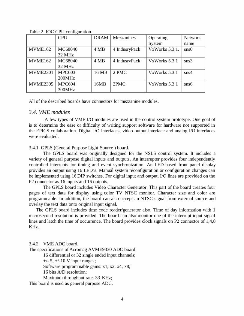
Table 2. IOC CPU configuration.CPU DRAM Mezzanines Operating
SystemNetworkname
MVME162 MC6804032 MHz
4 MB 4 IndusryPack VxWorks 5.3.1. sns0
MVME162 MC6804032 MHz
4 MB 4 IndusryPack VxWorks 5.3.1 sns3
MVME2301 MPC603200MHz
16 MB 2 PMC VxWorks 5.3.1 sns4
MVME2305 MPC604300MHz
16MB 2PMC VxWorks 5.3.1 sns6
All of the described boards have connectors for mezzanine modules.
3.4. VME modules A few types of VME I/O modules are used in the control system prototype. One goal of
is to determine the ease or difficulty of writing support software for hardware not supported inthe EPICS collaboration. Digital I/O interfaces, video output interface and analog I/O interfaceswere evaluated.
3.4.1. GPLS (General Purpose Light Source ) board.The GPLS board was originally designed for the NSLS control system. It includes a
variety of general purpose digital inputs and outputs. An interrupter provides four independentlycontrolled interrupts for timing and event synchronization. An LED-based front panel displayprovides an output using 16 LED’s. Manual system reconfiguration or configuration changes canbe implemented using 16 DIP switches. For digital input and output, I/O lines are provided on theP2 connector as 16 inputs and 16 outputs.
The GPLS board includes Video Character Generator. This part of the board creates fourpages of text data for display using color TV NTSC monitor. Character size and color areprogrammable. In addition, the board can also accept an NTSC signal from external source andoverlay the text data onto original input signal.
The GPLS board includes time code reader/generator also. Time of day information with 1microsecond resolution is provided. The board can also monitor one of the interrupt input signallines and latch the time of occurrence. The board provides clock signals on P2 connector of 1,4,8KHz.
3.4.2. VME ADC board.The specifications of Acromag AVME9330 ADC board:
16 differential or 32 single ended input channels;+/- 5, +/-10 V input ranges;Software programmable gains: x1, x2, x4, x8;16 bits A/D resolution;Maximum throughput rate. 33 KHz;
This board is used as general purpose ADC.

5
3.4.3. NSLS DAC boardThe specifications of DAC board:
8 channels; +/-10 V output range ;16 bits D/A resolution.
The test configuration measures the output signals of the DAC board using the ADC. Additionaltransition boards were used to directly connect 8 outputs of the DAC board to 8 inputs of anADC board.
4. Software configuration.
4.1. System softwareThe original EPICS design was based on using Unix systems for console/development and
VxWorks as the real-time operating system. At the present time the WindowsNT based version ofbase part of EPICS is available, but there are no organizations using EPICS without Unix server.
The Wintel platform is growing up in the market, and one of the important goals at BNLis the evaluation of Wintel computers as console/development base. Analysis and communicationswith the EPICS community indicates that at the present time EPICS based control systems MUSTuse a Unix console/development base. Some EPICS sites use Linux on Intel platform, butWindRiver does not support Linux as a cross development platform. The Linux base could beused for console applications but must have additional Unix (Solaris or HPUX) server forVxWorks cross development.
Initially EPICS release R3.12.2 was installed under HPUX at BNL. The VxWorks crossdevelopment system Tornado1.0.1 under HPUX was used. At the same time the Channel Accessclient library was used under Windows NT 4.0 for developing console applications.
The second step in the evaluation was the installation of the new EPICS release R3.13under Solaris on a Sun computer. Tornado and the board support package (BSP) for thePowerPC MVME2301 board was installed on the Sun computer. A few definitions were done inthe VxWorks sources for this PowerPC board. Most were placed in thevxworks/target/config/all/configAll.h file and enables the remote shell and other options which arenecessary for EPICS. The extended VME access definitions were done invxworks/target/config/mv2303/config.h file to enable A32 access from MVME2301 board toGPLS board. The evaluation of the configuration is proceeding.
The MEDM and Probe console applications now are available under Windows NT 4.0.These applications demand Exceed .dll libraries. The installation of these console applications wassuccessfully done on the Compaq computers.
4.2. EPICS related softwareEPICS software was evaluated during the prototype design. The most important tools are:
6
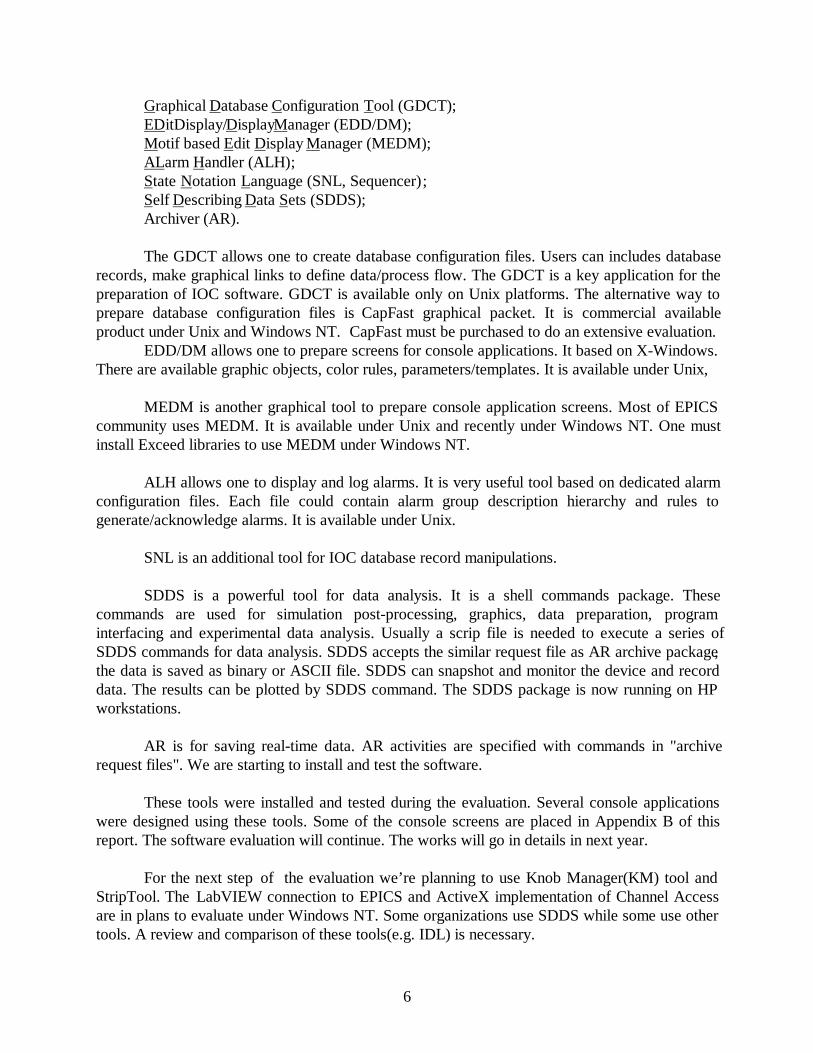
Graphical Database Configuration Tool (GDCT);EDitDisplay/DisplayManager (EDD/DM);Motif based Edit Display Manager (MEDM);ALarm Handler (ALH);State Notation Language (SNL, Sequencer);Self Describing Data Sets (SDDS);Archiver (AR).
The GDCT allows one to create database configuration files. Users can includes databaserecords, make graphical links to define data/process flow. The GDCT is a key application for thepreparation of IOC software. GDCT is available only on Unix platforms. The alternative way toprepare database configuration files is CapFast graphical packet. It is commercial availableproduct under Unix and Windows NT. CapFast must be purchased to do an extensive evaluation.
EDD/DM allows one to prepare screens for console applications. It based on X-Windows.There are available graphic objects, color rules, parameters/templates. It is available under Unix,
MEDM is another graphical tool to prepare console application screens. Most of EPICScommunity uses MEDM. It is available under Unix and recently under Windows NT. One mustinstall Exceed libraries to use MEDM under Windows NT.
ALH allows one to display and log alarms. It is very useful tool based on dedicated alarmconfiguration files. Each file could contain alarm group description hierarchy and rules togenerate/acknowledge alarms. It is available under Unix.
SNL is an additional tool for IOC database record manipulations.
SDDS is a powerful tool for data analysis. It is a shell commands package. Thesecommands are used for simulation post-processing, graphics, data preparation, programinterfacing and experimental data analysis. Usually a scrip file is needed to execute a series ofSDDS commands for data analysis. SDDS accepts the similar request file as AR archive package,the data is saved as binary or ASCII file. SDDS can snapshot and monitor the device and recorddata. The results can be plotted by SDDS command. The SDDS package is now running on HPworkstations.
AR is for saving real-time data. AR activities are specified with commands in "archiverequest files". We are starting to install and test the software.
These tools were installed and tested during the evaluation. Several console applicationswere designed using these tools. Some of the console screens are placed in Appendix B of thisreport. The software evaluation will continue. The works will go in details in next year.
For the next step of the evaluation we’re planning to use Knob Manager(KM) tool andStripTool. The LabVIEW connection to EPICS and ActiveX implementation of Channel Accessare in plans to evaluate under Windows NT. Some organizations use SDDS while some use othertools. A review and comparison of these tools(e.g. IDL) is necessary.

7
4.3. Development software.
4.3.1. Tornado cross development system.The Tornado 1.0.1 for HPUX/Solaris development package from WindRiver Systems was
used to develop VxWorks based real-time applications. Tornado is a network-based product thatprovides a modular tool-kit for host development system and set of board support packages(BSP) for the target processors. There are two installation of Tornado, one for HPUX host andMC68040 targets, and second for Solaris host and PowerPC targets. There are many options inthe Tornado package to debug real-time applications and monitor the operating system. Thiscross development system is also available under Windows NT, but there are no EPICS sitesusing this configuration.
4.3.2. Microsoft Visual C++The Visual C++ 5.0 software package was used to create WindowsNT console
applications. It based on Integrated Development Environment (IDE) tools called «DeveloperStudio». The IDE combines compiler, source debugger and on-line help information. The mostpopular is usage Microsoft Foundation Classes (MFC) library and extensions. During SNSproject evaluation few test applications were designed using this C++ library. The EPICS ChannelAccess land WinSock libaries were inserted into projects as binary .lib files. To support powerfulgraphical presentation the Olectra Chart library was used.
4.3.3. Olectra Chart library.The OlectraChart software package was used to create graphical high-level applications
under WindowsNT. Olectra Chart is a WindowsNT realization of the popular Unix XRTGraphlibrary. This package includes functions to create, manipulate and display graphics in an on-line oroff-line mode. OlectraChart adds new OLE control to windows that displays data graphically in awindow and can interact with a user. The chart is made up of a logical hierarchy of objects, andeach object has its own properties and methods that determine how the chart looks and functions.
Data to be graphed may come from any source and may be updated at any time. Any fontavailable from Windows NT may be used for heater, footer, legend, axis and text area annotation.Examples of using OlectraChart library presented at Appendix B, figures 2,3.
4.3.4. CapFastCapFast from 3-PHASE company is adopted by EPICS system for generating the
database channels and channel links in the graphics display. This software package is used as adatabase builder as GDCT in the EPICS. It has more powerful graphics displays and hierarchyfeatures compared to GDCT. The Capfast software package is being tested in HP-UX andWindowsNT. The EPICS channel symbol library is installed in the Capfast package. The filecreated by Capfast is schematic file. A series of programs are used to convert the schematic file toEPICS supported database file. The hardware feature of EPICS records is added to the databasefile during the conversion. The graphical schematic file created by Capfast is displayed in Figure 8at Appendix B.
Presently we only have a demo version of CapFast available for testing.
4.4. System administration

8
CVS("Concurrent Version System") is a system for managing source code underconcurrent development by one or more individual programmer. CVS is built on top of theRSC("Revision Control System"), for normal use you don't have to know anything about RCS inorder to use CVS. CVS requires RCS version 5.5 or higher. EPICS uses CVS to maintainprogram sources. The version R3.12.2 of EPICS works with CVS Release 1.5; the versionR3.13.0.beta4 and upper works with CVS Release 1.7.
CVS maintains the version branch tree of the software package. Different version of theprogram can be check out. Once the updating of the program is done, you need to commit theprogram to CVS. CVS allows multi-user working on the same program independetly, CVSupdates the newest version according to the commit results from all users. Now CVS is used tomaintain the developing program of EPICS in HP-UX.
5. Applications’ prototypes.
5.1. IOC device driversThe device and driver support is one of the important parts in real-time applications.
During the EPICS control system evaluation a few device/driver support routines were created.The GPLS board has front-panel switches and front-panel LED display. The board also has avideo text generator which as implemented as String Output EPICS record. The newdevice/driver support was designed to support this board.
devBiGplsFIN.c - device support for Binary Input EPICS record, it manipulates with 1 bitof input data;
devMbbiDirectGplsFIN.c - device support for MultiBit Binary Input Direct EPICS record, itretrieves a sixteen bit hardware value and converts it to an array of sixteen unsignedcharacters, each representing a bit of the word;
devMbboDirectGplsLED.c - device support for MultiBit Binary Output Direct EPICS record,it accumulates bits (in the fields B0-BF) as unsigned characters, and converts them to aword which is then written out to hardware;
devSoGplsV.c - device support for String Ouput EPICS record, it is used to output anarbitrary ASCII string;
drvGplsFIN.c - driver support for front-panel switches of GPLS board;drvGplsLED.c - driver support for front-panel LED display of GPLS board;drvGplsV.c - driver support for video text generator of GPLS board.
The new device/driver routines were designed to support Acromag 9330 ADC board and NSLSDAC board.
DevAiAvme9330Se.c - device support for Analog Input EPICS record, it obtains an analogvalue and converts it to engineering units, it is for single-ended version of ADC;
devAiAvme9330Di.c - same as above, but for differential version of ADC;

9
devAoLSDAC.c - device support for Analog Output EPICS record, it sends values toDACs;
drvAvme9330.c - driver support for Acromag 9330 ADC board;drvLSDAC.c - driver support for NSLS 8 channels DAC board.
These device/driver routines gives BNL some experience with the writing of EPICSdrivers. The digital I/O and analog I/O were installed and tested successfully. The high-levelconsole applications were also created to test this equipment. Several examples of screens arepresented in Appendix B of this report.
The state notation language was also evaluated. The test application was created togenerate a sine-wave output signal from the NSLS DAC board. This application can be started inthe IOC. The application checks the binary input from the front-panel switch of GPLS board andstarts or stops the sine-wave DAC generator. All sine-wave screen examples in Appendix B weregenerated by this real-time sequencer program.
5.2. Console computer applicationsTwo approaches were evaluated in the creation of control system prototype console
applications.The EPICS based approach assumes the use MEDM or EDD/DM tools for rapid
development of console application screens. In this case, the developer uses MEDM and justtypes the database value names during the graphical screen creation phase. All information aboutscreens and connections to IOCs is placed in .adl description files. This approach is popular inEPICS community and allows one to create powerful console applications with minimum efforts.A few console MEDM-based applications were designed. The MEDM allows using templates togenerate applications which use input parameter as IOC name or database record name. Thispossibility also has been evaluated. Some of the screens are presented in figures 1,6 and 7 ofAppendix B of this report. MEDM now is available under Windows NT. The example ofADC/DAC screen under WindowsNT is presented at figure 5 at Appendix B. This applicationwas originally design under Unix and one can use the same .adl. description files to run it underWindows NT. Some of other EPICS tools also were evaluated. The most important and popularis Alarm Handler (ALH) console application. This application uses input configuration text file,which describes hierarchy of devices, groups and assigned alarms states to each group, device orboth. The example of using ALH is presented at figure 4 at appendix B. Unfortunately, this tool isnot available under Windows NT.
The list of .adl files:adcdacp.adl - ADC/DAC control monitoring test application;addach.adl - screen for each channel in ADC/DAC monitoring;dact1.adl - DAC test application;LEDTestp.adl - LED display and control test, also monitoring the binary input;videop.adl - allows to put any ASCII string to co lor monitor via string output intrface.
Another way to create console applications is to write code using the tools and libraries toaccess and display data. The goal of this evaluation was getting experience to create dedicatedapplications. The Epidem application was designed under Windows NT using Microsoft VisualC++ 5.0, MFC general purpose library, OlectraChart graphical library and ChannelAccess library.

10
The examples of screens are presented at figures 2,3 at Appendix B. The Epidem application hassplit window, which display on-line history of behavior for several devices. The additional dialogbox can be used to adjust control values in the selected device. Using Visual C++ and powerfulgraphical libraries one can create their own applications which could be connected to IOCs.
lssns1:C:\epics\epidem - project directory of Epidem Windows NT application.
All console applications have connections to real-time equipment placed in IOCs. The setof I/O boards includes few GPLS digital I/O boards, Acromag 9330 ADC board and NSLS DACboard.
The input parameters availability allows us to use the same screens for different IOCs
6. PlansPlans for the coming year are discussed in this part of the report. There is more work to
do in many of the tasks described above and the work will continue. Other work planned includesthe installation of systems for specific purposes such as staff training, hardware or softwareevaluation or to gain experience with some portions of the control system.
6.1. Control systemThe hardware mezzanine concept is very popular now and is extensively applied in CERN,
ANL and other accelerator laboratories all over the world. The main idea of this concept is usingthe mother boards as carriers which provides generic functionality for application-specificdaughter boards. More than 300 modules made under this technology are available on markettoday. Among them there are intelligent and non-intelligent carries, ADC and DAC, digital I/O,serial and networking interfaces, motor controllers and DSP, telecommunications and businterfaces. 90% of them are driver supported in real-time operation systems.
One step in the control system evaluation is to use several types of IndustryPack (IP)modules. The GPIB and multichannel serial interface IP modules are already used in the EPICScommunity.
The CompactPCI technology is becoming a standard for controls in some industries. Theevaluation of CompactPCI crate and CPU is a possible next step. A single-board computer basedon the PentiumII is now available from Motorola.(Model name is CPV5300). Unfortunately, thereis little experience in the EPICS community with CompactPCI. The CompactPCI has somelimitations such as the number of slots(8) and the availability of I/O boards. This may prevent itbeing used everywhere but it may be useful in some applications.
The VXI crate and I/O modules should be evaluated during next step of controldevelopment process. A VXI crate that can use standard VME CPU boards was demonstrated atANL. Previously there were very few CPU boards,supported by VxWorks for the VXI bus.
6.2. Magnet power supplies

11
The power supplies control will based on RHIC design. The RHIC control system uses ageneral purpose multiplexed analog to digital converter system and waveform generator board.The ADC system consists of a custom intelligent VME based controller module and 14-bit 64-channel multiplexed A/D converter module. The design features two independent scan groups,where one scan group is capable of acquiring 64 channels at 60 Hz, concurrently with the secondscan group acquiring data at an aggregate rate of up to 80k samples/second. Data stored in acircular static RAM buffer on the controller module. The waveform generator applies pre-programmed control functions in the different stages of accelerator facility cycles to drive powersupplies. The output of waveform generator is the sum of one time-dependent function and twomachine parameter-dependent functions. It will be necessary to develop device/driver support tointerface with EPICS for these boards. The high-level applications will be necessary to evaluatethe power supplies control.
6.3. RF system
A test system will be installed to give the RF group EPICS experience. This may be ashared system for the first year or until we find each group needs their own system.
6.4. Vacuum systemThe vacuum equipment control and monitoring may be based on PLCs with Ethernet
interface. The goal of he evaluation is to compare this interface with other standard interface andto connect the equipment to VME and develop EPICS device/driver support.
6.5. Beam diagnosticFast ADC multichannel modules are planned for the beam diagnostic systems. At the
present time the 8 channel 12 bit VME module is designed for one RHIC beam diagnostic system.The module contains 128Kwords per each ADC channel. The maximum sampling frequency is 10MHz. Common external triggering is available. An internal programmable clock generator allowstesting the module. It will be necessary to develop device/driver EPICS support for this moduleand to evaluate the whole data acquisition system. The capability to collect large data arrays fromthe IOC is an important part of the evaluation.
It’s planned to build a prototype device for beam measurement and to test the hardware inthe AGS Linac. Its possible that higher performance boards(20-40MHz) will have to be tested.
6.6. Timing systemThe RHIC timing system will be evaluated during the next step of SNS control system
project. The RHIC timing control includes few VME modules. The V100 encoder module is usedto transmit event codes to eventlink. This encoder module can be connected to event inputmodule bus. The V101 event input module determines the relative priority of its 16 event triggerinputs. Sixteen V101 input modules can support 256 events. The V102 delay module contains 8event output channels with programmable triggers, delay times, and delay clocks. Thedevice/driver support development is necessary to evaluate these modules.
6.7. Magnet measurement

12
The magnet measurement system control will be necessary during initial phase of magneticelements design and testing. During next step of SNS control system evaluation we’re planning toevaluate and compare LabVIEW and EPICS approaches to magnet measurement system. One ofpossible solution is connection between LabVIEW and EPICS, which was already tested at LBLEPICS site.
6.8. NetworkingThe 100 Mbit Fast Ethernet is in the evaluation plan for the control system. Most of the
new console computers as well as single-board computers have this option. The network itselfmust have the necessary components to allow 100MHZ transfers between nodes. During nextyear the local network will be upgraded so 100 Mhz testing can proceed.
Neworking will be setup so the EPICS control system can be distributed over several sitesat BNL where SNS personnel will be working. The network must allow secure communications,remote booting, access to a central server etc.
One of our goals is to measure the console update rates fo r screens with a varying numberof parameters displayed.
6.9. PLCs
PLC's are proposed for use in the control of power supplies, RF and vacuum systems forthe SNS. The power supply, RF and vacuum groups have experience with these devices and planto use them in the subsystems design. In the computer control structure shown in Figure 1 thePLC is located at the lower level and communicates with the device level directly. The upper levelVME system will control the PLC through the universal remote I/O link. Each PLC has local andremote control functionality.
Much of the BNL experience is with the Allen-Bradley hardware. PLC products from theAllen-Bradley company are divided into two series according to the PLC processor. PLC-5 isused to control large-sized systems. SLC-500 is a newer and cost-efficiency system, it is good forlocal control. It's likely both of them will be used in the future control system.
As first step, a PLC-5 processor, Analog I/O, VME scanner and software package areused to build the lower level of the control system. The VME scanner is used to link the VME buswith the PLC system.
Presently we have reviewed the specifications and literature with members of the AGSwho work with this hardware. When PLC hardware and software is obtained, applicationsoftware will be developed in the EPICS system.
6.10. Fieldbus
PLC’s are one type of field bus. Other types commonly used are GPIB and Serialcommunications(RS232, RS422, RS485). There are proprietary field bus’s used at various labs.As an example, AGS/RHIC has a proprietary bus for control of power supplies. At BESSY labthey use the CAN bus as a power supply controller. We will investigate and compare the variousfieldbus options.

13
6.11. CPU Boards
While EPICS has been ported to the PowerPC boards extensive testing has not beencompleted. Testing the interrupt structure by simultaneously inserting several high data ratesignals at different interrupt levels and testing for long periods (days) is still to be done. RunningEPICS using clock rates much higher than normal will be tested. Some applications in the pasthave required processing input signals at several hundred HZ.
The best procedure for booting the CPU boards will be investigated. We have presentlyimplemented the BOOP procedure. Other alternatives such as using flash memory will beinvestigated.
6.12. DatabaseOne of the key points of the control system is database configuration. For the first part of
the SNS control system evaluation a brief analysis of EPICS sites was done. It appears that theBESSY-II synchrotron radiation source and KEKB project have made the most progress in usinga relational database system with EPICS. Both use ORACLE as the database.
The KEKB approach can automatically generate EPICS real-time database files, MEDM.adl files and VxWorks startup files.
BESSY-II has a more complex approach [4]. The database contains not only EPICSrelated information, but accelerator modeling data sets, full equipment descriptions and so on. TheBESSY-II approach seems more useful. It is a general-purpose database for the whole SNSproject, not only for control of storage ring, but for all systems and for all facilities. There are datainput interfaces to AutoCAD, MS-Excel as well as to a text editor. Exported data can beimported by C/C++ or SQL programs, Web forms, MS-Excel via ODBC etc. BESSY-II also hasimplementation of interface to EPICS real-time database. The Web interface to the ORACLEdatabase allows some simple interactions and monitoring.
We plan to evaluate the ORACLE data base management system during the next step ofcontrol system design phase. It seems a collaboration with BESSY which has made more progressin this area compared to any other EPICS site would be useful. BESSY recommends ‘early set upof the database management system’ as key to a successful implementation.
6.13. NT WorkstationsThe use of NT workstations as an operator console for the SNS is a possibility. We
started to explore the feasibility of using NT by implementing a few applications as shown in theexamples. We will continue the evaluation of NT software, hardware and tools by porting someapplications to an NT system. We need more experience before a choice could be made betweenUnix and NT workstations.
7. List of hardware/software

14
The list of hardware and software products presented here includes product which are already inthe evaluation phase and products which plan to be tested and evaluated.
7.1. Hardware
1. SUN workstation (Ultra 5)2. HP workstation (HP735/125)3. VME crate4. Motorola MVME162 single-board computer5. Motorola MVME 2301 single-board computer6. Color TV/monitor7. VME input/output modules
GreenSpring VIP610 IndustryPack passive carrierVMIC 4116 8 channel 16 bit analog output boardVMIC 3122 64 channel 16 bit 100KHz analog input board
8. Allen-Bradley PLC modulePLC-5 processorVME remote I/O scannerAnalog I/OPLC software interface card
9. CompactPCIMotorola CPX2108 8 slot chassyMotorola CPV 5300 Pentium II based single-board computer
10. IndustryPack I/O mezzanine modulesGPIB interface GreenSpring IP-488RS-232 interface GreenSpring IP-Octal 232ADC 8 channel 16 bit GreenSpring IP-16ADCDAC 3 channel 16 bit GreenSpring IP-16DACDigital I/O 24 bit GreenSpring IP-Unidig-E
11. Timing System Boards.
7.2. Software
1. VxWorks Tornado Development System (HP host+MC680x0 target)2. VxWorks Tornado Development System (Sun host+PowerPC target)3. Microsoft Visual C++ 5.04. Microsoft Office 7.05. Hummingbird XDK6. OlectraChart 5.0 Library7. ORACLE database8. CapFast development utility9. XRTGraph graphical library10. RSLOGIC5 PLC development system11. LabVIEW system

15
12. Presentation Software (IDL)13. Scientific Software(Matlab, Mathematica)
8. References
1. Lewis S., et. al. "Distributed Implementation Plan for a Large, Distributed Accelerator ControlSystem" in Proceedings of International Conference on Accelerator and Large ExperimentalPhysics Control Systems,(ICALEPCS'97 Beijing, China 1997)2. Kramer M., Dalesio J., et. al. "The Experimental Physics and Industrial Control SystemArchitecture: past, present and future", in Proceedings of International Conference on Acceleratorand Large Experimental Physics Control Systems,(ICALEPCS'93 Berlin, Germany 1993)3. Dalesio, L. R., Kraimer, M.R., Kozubal, A. J., "EPICS Architecture," in Proceedings ofInternational Conference on Accelerator and Large Experimental Physics Control Systems,(ICALEPCS’91, KEK, Tsukuba, Japan, 1991),pp. 278-282.4. R.Muller, et. al. “Significance of a Comprehensive Relational Database System for ModernAccelerator Controls” in Proceedings of International Conference on Accelerator and LargeExperimental Physics Control Systems,(ICALEPCS'97 Beijing, China 1997)
9. WWW links
1. SNS project web-site http://www.ornl.gov/~nsns/nsns.html2. EPICS main pagehttp://www.aps.anl.gov/asd/controls/epics/EpicsDocumentation/WWWPages/3. EPICS web-site at LANL http://www.atdiv.lanl.gov/aot8/epics/epicshm.htm4. EPICS web-site at Jefferson Lab. http://www.jlab.org/accel/documents/epics_doc.html5. EPICS web-site at LBL http://csg.lbl.gov/CSG.html6. Win River Systems http://www.wrs.com/7. OlectraChart library http://www.klgroup.com/8. Motorola Computer Group http://www.mcg.mot.com9. BESSY-II Oracle database page http://oracle.bessy.de/10. RHIC control system hardware page http://www.rhichome.bnl.gov/Hardware/

16
Appendix A
IOCs VxWorks boot configurations
1. sns0 (MVME162)
boot device:eihost name:ls7501file name:/users2/u3/epics/boot/iocs/sns0/vxworksinet on ethernet:130.199.195.210host inet:130.199.194.23flags:0x8target name:sns0startup script:/users2/u3/epics/boot/iocs/sns0/startup.cmd
2. sns3 (MVME162)
boot device:eihost name:ls7501file name:/users2/u3/epics/boot/iocs/sns3/vxworksinet on ethernet:130.199.195.213host inet:130.199.194.23flags:0x8target name:sns3startup script:/users2/u3/epics/boot/iocs/sns3/startup.cmd
3. sns4 (MVME2301)
boot device:dchost name:lssun1file name:/users/epics/master/vxworks/target/config/mv2303/vxworksinet on ethernet:130.199.195.214host inet:130.199.195.223flags:0x2target name:sns4startup script:/users/epics/snseva/iocBoot/iocsns4/st.cmd

1
Appendix B
Console application screen examples
Figure 1. MEDM based demo application under HPUX.
The application allows setting 8 DAC channels and monitoring 8 ADC channels. It uses theAcromag 9330 ADC board and NSLS DAC board. A sine wave is generated by a sequencerprogram running in the IOC and writing to the DAC board. Users can select any DAC channeland set it using slider.
2
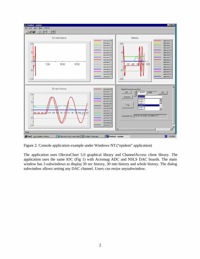
Figure 2. Console application example under Windows NT.(“epidem” application)
The application uses OlectraChart 5.0 graphical library and ChannelAccess client library. Theapplication uses the same IOC (Fig 1) with Acromag ADC and NSLS DAC boards. The mainwindow has 3 subwindows to display 30 sec history, 30 min history and whole history. The dialogsubwindow allows setting any DAC channel. Users can resize any subwindow.

3
Figure 3. Another version of view for “epidem” applicationThe 30 sec history subwindow was resized to full window size.

4
Figure 4. Alarm Handler demo application.The Alarm Handler application has a window with a list of monitored channels. In case of analarm the color of the rectangle placed near the channel name will be red or yellow. In thisdemonstration the MEDM based application was used to set a DAC output value to get an alarm.

5
Figure 5. MEDM based application running under Windows NT.The MEDM based application connects to the IOC using ChannelAccess. The MEDM screenunder WindowsNT is very similar to HPUX screen at figure 1. The Probe application screenplaced at bottom part allows adjusting the DAC setpoint.

6
Figure 6. MEDM edit session example under Windows NTIt is a standard MEDM screen editable session.
7
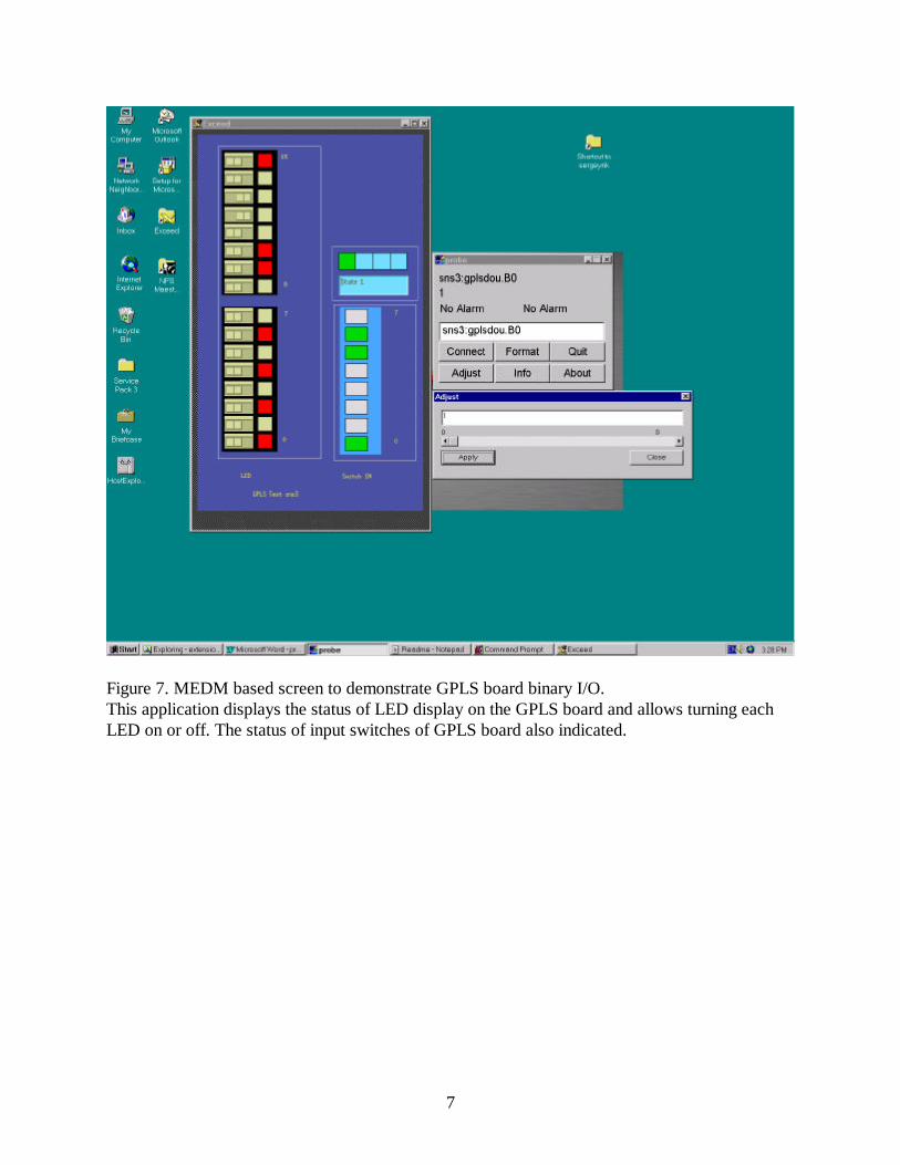
Figure 7. MEDM based screen to demonstrate GPLS board binary I/O.This application displays the status of LED display on the GPLS board and allows turning eachLED on or off. The status of input switches of GPLS board also indicated.

8
Figure 8. CapFast graphical database configuration example.