boardman solar energy facility—exhibit a ... · boardman solar energy facility—exhibit a page...
TRANSCRIPT

BOARDMAN SOLAR ENERGY FACILITY—EXHIBIT A
FINAL APPLICATION FOR SITE CERTIFICATE PAGE A-I
EXHIBIT A APPLICANT INFORMATION
OAR 345-021-0010(1)(a)
TABLE OF CONTENTS
Page
A.1 APPLICANT AND CONTACT PERSONS ............................................................................................ A-1
A.2 PARTICIPATING ENTITIES .............................................................................................................. A-2
A.3 CORPORATION STATUS ................................................................................................................. A-2
A.4 OWNERSHIP .................................................................................................................................. A-3
A.5 ADDITIONAL APPLICANT INFORMATION ...................................................................................... A-3
ATTACHMENTS
A-1 Articles of Organization and Authorization A-2 Proof of Registration to do Business in Oregon

BOARDMAN SOLAR ENERGY FACILITY—EXHIBIT A
FINAL APPLICATION FOR SITE CERTIFICATE PAGE A-1
A.1 APPLICANT AND CONTACT PERSONS
(A) Information about the applicant and participating persons, including:
OAR 345-021-0010(1)(A). The name and address of the applicant including all co-owners of the proposed facility, the name, mailing address, email address and telephone number of the contact person for the application, and if there is a contact person other than the applicant, the name, title, mailing address, email address and telephone number of that person;
Response:
Name and mailing address of Applicant:
Boardman Solar Energy LLC c/o Invenergy Solar Development LLC One South Wacker Drive, Suite 1800 Chicago, IL 60606
Applicant contact persons with mailing address, email address, and telephone number:
Laura Miner Boardman Solar Energy LLC c/o Invenergy Solar Development LLC 1001 SE Division Street, Suite 3 Portland, OR 97202 [email protected] (503) 964-8900
Michael Baird Boardman Solar Energy LLC c/o Invenergy Solar Development LLC 2580 West Main Street, Suite 200 Littleton, CO 80120 [email protected] (303) 797-5472
Contact persons other than the Applicant:
Paul Seilo, Project Manager CH2M HILL Engineers, Inc. 2020 SW 4th Avenue, Suite 300 Portland, OR 97201 [email protected] (503) 736-4012
Sarah Stauffer Curtiss, Partner Stoel Rives LLP 760 SW Ninth Avenue, Suite 3000 Portland, OR 97205 [email protected](503) 294-9829
BOARDMAN SOLAR ENERGY FACILITY—EXHIBIT A
PAGE A-2 FINAL APPLICATION FOR SITE CERTIFICATE
A.2 PARTICIPATING ENTITIES
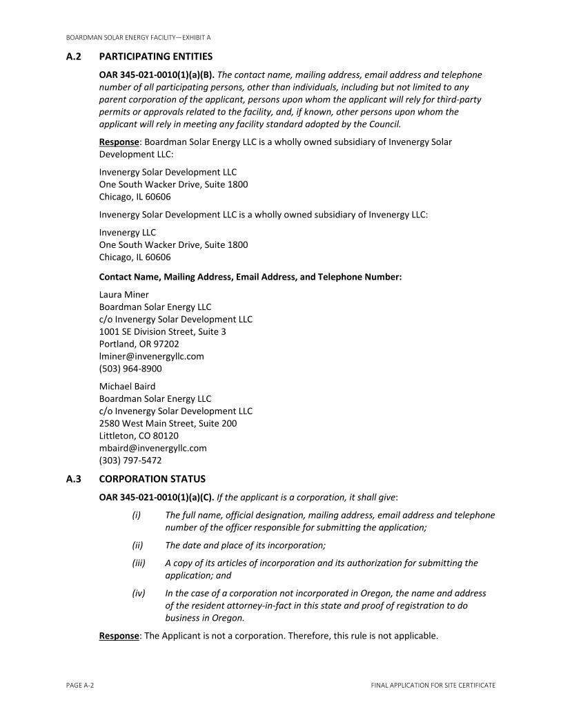
OAR 345-021-0010(1)(a)(B). The contact name, mailing address, email address and telephone number of all participating persons, other than individuals, including but not limited to any parent corporation of the applicant, persons upon whom the applicant will rely for third-party permits or approvals related to the facility, and, if known, other persons upon whom the applicant will rely in meeting any facility standard adopted by the Council.
Response: Boardman Solar Energy LLC is a wholly owned subsidiary of Invenergy Solar Development LLC:
Invenergy Solar Development LLC One South Wacker Drive, Suite 1800 Chicago, IL 60606
Invenergy Solar Development LLC is a wholly owned subsidiary of Invenergy LLC:
Invenergy LLC One South Wacker Drive, Suite 1800 Chicago, IL 60606
Contact Name, Mailing Address, Email Address, and Telephone Number:
Laura Miner Boardman Solar Energy LLC c/o Invenergy Solar Development LLC 1001 SE Division Street, Suite 3 Portland, OR 97202 [email protected](503) 964-8900
Michael Baird Boardman Solar Energy LLC c/o Invenergy Solar Development LLC 2580 West Main Street, Suite 200 Littleton, CO 80120 [email protected](303) 797-5472
A.3 CORPORATION STATUS
OAR 345-021-0010(1)(a)(C). If the applicant is a corporation, it shall give:
(i) The full name, official designation, mailing address, email address and telephone number of the officer responsible for submitting the application;
(ii) The date and place of its incorporation;
(iii) A copy of its articles of incorporation and its authorization for submitting the application; and
(iv) In the case of a corporation not incorporated in Oregon, the name and address of the resident attorney-in-fact in this state and proof of registration to do business in Oregon.
Response: The Applicant is not a corporation. Therefore, this rule is not applicable.

BOARDMAN SOLAR ENERGY FACILITY—EXHIBIT A
FINAL APPLICATION FOR SITE CERTIFICATE PAGE A-3
A.4 OWNERSHIP
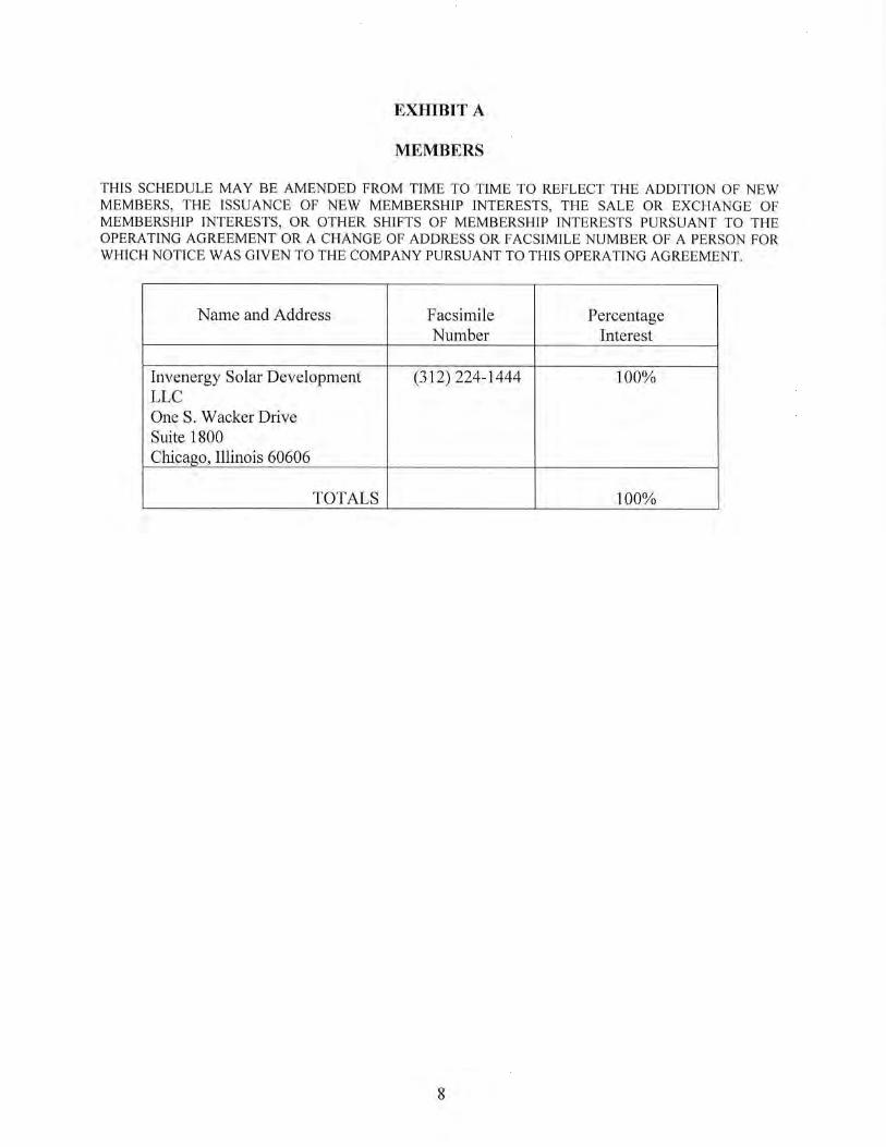
OAR 345-021-0010(1)(a)(D). If the applicant is a wholly owned subsidiary of a company, corporation or other business entity, in addition to the information required by paragraph (C), it shall give the full name and business address of each of the applicant’s full or partial owners;
Response: Boardman Solar Energy LLC is a wholly owned subsidiary of Invenergy Solar Development LLC. The full name and business address are as follows:
Invenergy Solar Development LLC One South Wacker Drive, Suite 1800 Chicago, IL 60606 (312) 224-1400
A.5 ADDITIONAL APPLICANT INFORMATION
OAR 345-021-0010(1)(a)(E). If the applicant is an association of citizens, a joint venture or a partnership, it shall give:
(i) The full name, official designation, mailing address, email address and telephone number of the person responsible for submitting the application;
(ii) The name, business address and telephone number of each person participating in the association, joint venture or partnership and the percentage interest held by each;
(iii) Proof of registration to do business in Oregon;
(iv) A copy of its articles of association, joint venture agreement or partnership agreement and a list of its members and their cities of residence; and
(v) If there are no articles of association, joint venture agreement or partnership agreement, the applicant shall state that fact over the signature of each member;
Response: The Applicant is not an association of citizens, a joint venture, or a partnership. Therefore, this rule is not applicable.
OAR 345-021-0010(1)(a)(F). If the applicant is a public or governmental entity, it shall give:
(i) The full name, official designation, mailing address, email address and telephone number of the person responsible for submitting the application; and
(ii) Written authorization from the entity’s governing body to submit the application;
Response: The Applicant is not a public or governmental entity. Therefore, this rule is not applicable.
OAR 345-021-0010(1)(a)(G). If the applicant is an individual, the individual shall give his or her mailing address, email address and telephone number.
Response: The Applicant is not an individual. Therefore, this rule is not applicable.
OAR 345-021-0010(1)(a)(H). If the applicant is a limited liability company, it shall give:
(i) The full name, official designation, mailing address, email address and telephone number of the officer responsible for submitting the application;

BOARDMAN SOLAR ENERGY FACILITY—EXHIBIT A
PAGE A-4 FINAL APPLICATION FOR SITE CERTIFICATE
Response: The officer responsible for submitting the Application for Site Certificate is as follows:
Michael Baird, Vice President Boardman Solar Energy LLC c/o Invenergy Solar Development LLC 2580 West Main Street, Suite 200 Littleton, CO 80120 [email protected](303) 797-5472
(ii) The date and place of its formation;
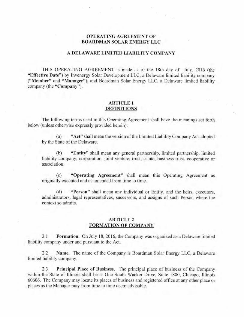
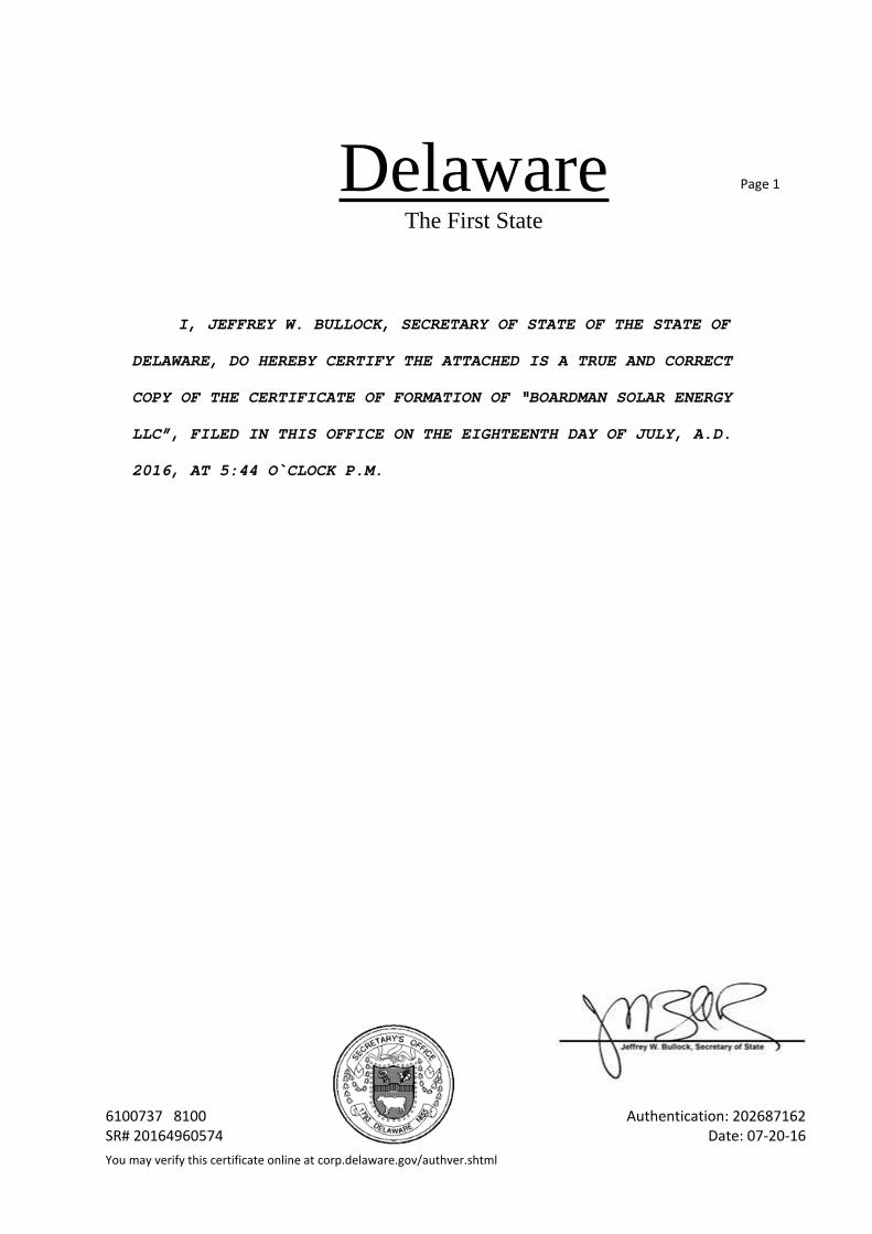
Response: Boardman Solar Energy LLC was formed in the State of Delaware on July 18, 2016.
(iii) A copy of its articles of organization and its authorization for submitting the application; and
Response: A copy of the articles of organization and authorization is provided in Attachment A-1.
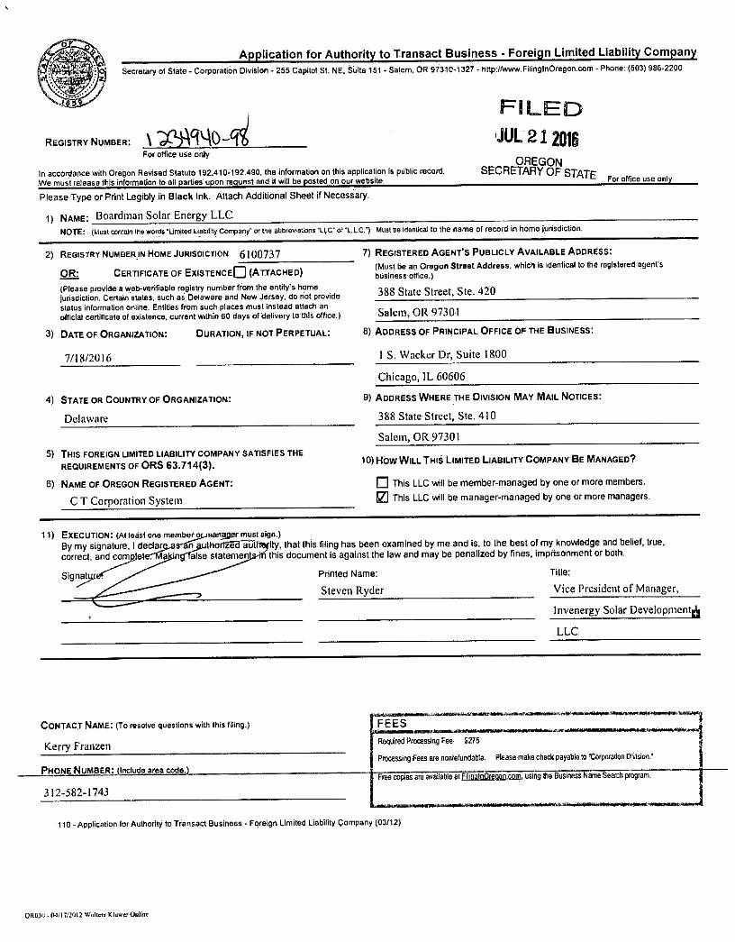
(iv) In the case of a limited liability company not registered in Oregon, the name and address of the resident attorney-in-fact in this state and proof of registration to do business in Oregon.
Response: The resident attorney-in-fact is as follows:
Sarah Stauffer Curtiss, Partner Stoel Rives LLP 760 SW Ninth Avenue, Suite 3000 Portland, OR 97205 [email protected](503) 294-9829
Proof of registration to do business in Oregon is provided in Attachment A-2.

Attachment A‐1 Articles of Organization and
Authorization


DelawareThe First State
Page 1
6100737 8100 Authentication: 202687162SR# 20164960574 Date: 07-20-16You may verify this certificate online at corp.delaware.gov/authver.shtml
I, JEFFREY W. BULLOCK, SECRETARY OF STATE OF THE STATE OF
DELAWARE, DO HEREBY CERTIFY THE ATTACHED IS A TRUE AND CORRECT
COPY OF THE CERTIFICATE OF FORMATION OF “BOARDMAN SOLAR ENERGY
LLC”, FILED IN THIS OFFICE ON THE EIGHTEENTH DAY OF JULY, A.D.
2016, AT 5:44 O`CLOCK P.M.

Attachment A‐2 Proof of Registration to do
Business in Oregon


BOARDMAN SOLAR ENERGY FACILITY—EXHIBIT B
FINAL APPLICATION FOR SITE CERTIFICATE PAGE B-I
EXHIBIT B FACILITY DESCRIPTION
OAR 345-021-0010(1)(b)
TABLE OF CONTENTS
Page
B.1 DESCRIPTION OF PROPOSED FACILITY .......................................................................................... B-1 B.1.1 Electrical Generating Capacity ......................................................................................... B-1 B.1.2 Major Components, Structures, and Systems ................................................................. B-1 B.1.3 Site Plan ........................................................................................................................... B-2 B.1.4 Spill Containment ............................................................................................................. B-2 B.1.5 Fire Prevention ................................................................................................................. B-2 B.1.6 Thermal Power and Liquefied Natural Gas Plants ........................................................... B-3
B.2 RELATED OR SUPPORTING FACILITIES .......................................................................................... B-3 B.2.1 Collection System ............................................................................................................. B-3 B.2.2 Generator Step-up Transformer and Substation ............................................................. B-4 B.2.3 Transmission Line ............................................................................................................. B-4 B.2.4 Point of Interconnection .................................................................................................. B-4 B.2.5 Control House .................................................................................................................. B-4 B.2.6 Operations and Maintenance Building ............................................................................ B-4 B.2.7 Access Road ..................................................................................................................... B-5 B.2.8 Service Roads and Gates .................................................................................................. B-5 B.2.9 Temporary Staging Areas ................................................................................................. B-5
B.3 DIMENSIONS OF MAJOR STRUCTURES AND FEATURES ............................................................... B-5
B.4 TRANSMISSION LINE ..................................................................................................................... B-5 B.4.1 Length .............................................................................................................................. B-6 B.4.2 Right-of-Way .................................................................................................................... B-6 B.4.3 Rating and Dimensions .................................................................................................... B-6
B.5 CONSTRUCTION SCHEDULE .......................................................................................................... B-6
FIGURES
B-1 Vicinity Map B-2 Example of Module Block Components

BOARDMAN SOLAR ENERGY FACILITY—EXHIBIT B
FINAL APPLICATION FOR SITE CERTIFICATE PAGE B-1
OAR 345-021-0010(1)(b) Information about the proposed facility, construction schedule and temporary disturbance of the site, including:
B.1 DESCRIPTION OF PROPOSED FACILITY
B.1.1 Electrical Generating Capacity
OAR 345-021-0010(1)(b)(A)(ii) A description of the proposed energy facility, including as applicable: (i) The nominal electric generating capacity and the average electrical generating capacity, as defined in ORS 469.300.
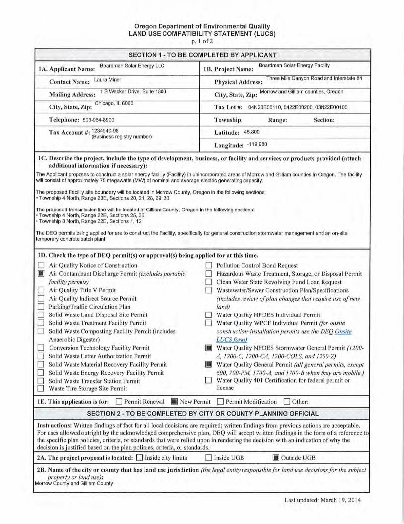
Response: Boardman Solar Energy LLC (Applicant) proposes to construct the Boardman Solar Energy Facility (Facility) in unincorporated areas of Morrow and Gilliam counties in Oregon (see Figure B-1 map of vicinity). The Facility will consist of approximately 75 megawatts (MW) of nominal and average electric generating capacity1.
B.1.2 Major Components, Structures, and Systems
OAR 345-021-0010(1)(b)(A)(ii) Major components, structures and systems, including a description of the size, type and configuration of equipment used to generate electricity and useful thermal energy.
Response: The Facility will generate electricity using multiple arrays of photovoltaic (PV) solar panels connected to electrical infrastructure. (The term “array” refers to panels wired in series and in parallel.) Solar panels generate electricity by means of a photoelectric effect whereby the materials in the panels absorb the sun’s energy in the form of photons and release electrons. The capture of these free electrons produces an electrical current that can be collected and supplied to the electrical power grid.
Solar Modules. The PV solar panels, known in the industry and referenced in this Exhibit and application as modules, will be installed to form 30 2.5-MW module blocks. Module block components will consist of the solar modules themselves, trackers, racks, posts, cabling, inverters, and transformers. Additional detail on each component is provided below. Figure B-2 provides an example illustration of module block components.
Trackers and Racks. The solar panel specification used for the Facility design is a 72-cell, 355-watt polycrystalline module on a single-axis tracker. The modules will be manufactured by Jinko Solar or a comparable firm. Each module measures approximately 6.4 by 3.3 feet and will be placed on a nonspecular metal galvanized steel rack with 10 to 30 other modules.
Each set of racked modules will be mounted approximately 4 feet off the ground on a single-axis tracker that rotates 45 degrees to the east and west. The Facility will use a tracker manufactured by NexTracker or a comparable firm. The trackers will be made of nonspecular metal galvanized steel. Refer to Figure B-2 for an example of an installed module with a tracker.
Posts. Each tracker will be supported by steel posts; post depth will vary depending on soil conditions but are typically 8 feet below the surface. If soil conditions require it, concrete foundations will be used. For purposes of this application, impact calculations assume the use of concrete foundations for all posts. Approximately 73,125 posts will be installed. Post locations will be determined by the ground coverage ratio (GCR). The planned GCR is 33 percent, meaning that the area occupied by the panels (when tilted horizontally) will be 33 percent of the total area covered. This will minimize the amount of shading from modules onto others.
1 Based on the Oregon Revised Statute 469.300(4) definition of average generating capacity for all energy facilities besides wind and geothermal.

BOARDMAN SOLAR ENERGY FACILITY —EXHIBIT B
PAGE B-2 FINAL APPLICATION FOR SITE CERTIFICATE
Cabling. The current produced by solar modules is in the form of direct current (DC). Within each module block, several DC electrical cables on the back of modules will aggregate (also referred to as string) produced electricity from approximately 28 modules each into a combiner box. Approximately 15 combiner boxes will be located throughout each module block for a total of approximately 465 total combiner boxes. A larger DC cable will run between each combiner box and then to the module block inverter. This cable will hang underneath the modules. Refer to Figure B-2 for an example of the cabling. From the inverters, the AC electricity is aggregated via underground 34.5-kilovolt (kV) cables to the Facility substation (see Section B.2.1).
Inverters. In order to be sent to the electrical grid, the DC current must be converted into alternating current (AC) power, and inverters serve this function. The conversion is accomplished by rapidly switching the DC power supply. By varying the length of time that the switch is on, as well as the polarity, the positive and negative swells of an AC wave are created. This waveform is then smoothed with an output filter. Inverters employ several advanced control systems, switching algorithms, and ancillary services for both the input and output stages. For the input stage, the inverters can manipulate the DC voltage to ensure maximum power harvest of input, and on the output various sensors ensure that AC power production is in accordance with regulatory requirements. The Facility will use 30 SMA Sunny Central 2500 inverters or similar. The inverter specification will fully comply with the applicable requirements of the National Electrical Code and Institute of Electrical and Electronics Engineers standards.
Transformers. The inverter AC output voltage (480 volts) will be stepped up to a higher-voltage (34.5 kV) by pad-mounted transformers designed to integrate with the SMA Sunny Central 2500 inverter. The Facility will have 30 transformers that are co-located with the inverters. The transformers will be mounted on concrete pads. Refer to Figure B-2 for an example of a transformer. Each transformer will contain approximately 650 gallons of oil.
B.1.3 Site Plan
OAR 345-021-0010(1)(b)(A)(iii) A site plan and general arrangement of buildings, equipment and structures.
Response: An overall site plan showing the proposed general arrangement of buildings, equipment, and structures is provided in Figure C-1 (Facility Layout) of Exhibit C. Additional details are provided in Figure C-2 (Facility Layout Details) of Exhibit C.
B.1.4 Spill Containment
OAR 345-021-0010(1)(b)(A)(iv) Fuel and chemical storage facilities, including structures and systems for spill containment
Response: The transformers are the only structures that contain oil and a spill prevention control and countermeasure plan (SPCC plan) will be put in place prior to construction. As part of the SPCC plan, the transformers will be regularly monitored for leaks and measures will be put in place if any are found to quickly control and remove oil. The GSU transformer will have a concrete catchment system sized at approximately 1.25 times the amount of oil inside the transformer.
B.1.5 Fire Prevention
OAR 345-021-0010(1)(b)(A)(v) Equipment and systems for fire prevention and control
The equipment will meet National Electrical Code and Institute of Electrical and Electronics Engineers standards and will not pose a significant fire risk. Facility roads will be sufficiently sized for emergency vehicle access in accordance with 2014 Oregon Fire Code Section 503 and Appendix D (Fire Apparatus Access Roads). Specifically, roads will be all-weather gravel compacted and 20 feet wide with an internal turning radius of 28 feet and less than 10 percent

BOARDMAN SOLAR ENERGY FACILITY—EXHIBIT B
FINAL APPLICATION FOR SITE CERTIFICATE PAGE B-3
grade. A perimeter road with additional space will provide a 50-foot, noncombustible, defensible space clearance, although only a 10-foot clearance is required under 2014 Oregon Fire Code Section 605.12.1. The rest of the ground in the Facility will be managed in accordance with Oregon Fire Code requirements. Under the 2014 Oregon Fire Code Section 605.12.2, the area under and around the installation will have a gravel base or other noncombustible base that is approved by the fire code official and does not create a dust hazard. This requirement is noted on the Facility Layout Details (Exhibit C Figure C-2B), and the base will be kept free of vegetation in accordance with the Revegetation and Noxious Weed Control Plan (Exhibit P Attachment P-6). In the rare event of an electrical fire in the module blocks or substation, it is likely that Facility staff will monitor and contain the fire, but not try to extinguish it. The control house and operations and maintenance (O&M) building will have smoke detectors, fire extinguishers, and eyewash stations to protect the buildings and workers.
B.1.6 Thermal Power and Liquefied Natural Gas Plants
OAR 345-021-0010(1)(b)(A)(vi) For thermal power plants:
(I) A discussion of the source, quantity and availability of all fuels proposed to be used in the facility to generate electricity or useful thermal energy.
(II) Process flow, including power cycle and steam cycle diagrams to describe the energy flows within the system.
(III) Equipment and systems for disposal of waste heat.
(IV) The fuel chargeable to power heat rate.
OAR 345-021-0010(1)(b)(A)(vii) For surface facilities related to underground gas storage, estimated daily injection and withdrawal rates, horsepower compression required to operate at design injection or withdrawal rates, operating pressure range and fuel type of compressors
OAR 345-021-0010(1)(b)(A)(viii) For facilities to store liquefied natural gas, the volume, maximum pressure, liquefaction and gasification capacity in thousand cubic feet per hour.
Response: The Facility is not a thermal power plant nor does it store liquefied natural gas. Therefore, these rules are not applicable.
B.2 RELATED OR SUPPORTING FACILITIES
OAR 345-021-0010(1)(b)(B) A description of major components, structures and systems of each related or supporting facility.
Related or supporting facilities consist of the collection system, 34.5-kV/115-kV generator step-up (GSU) transformer and substation, 115-kV transmission line, point of interconnection (POI) line tap, control house, O&M building, a private main access road, private service roads and gates, and a temporary staging area. Figure C-1 in Exhibit C shows the layout of these facilities within the site boundary. Figure C-2 (five sheets) shows additional layout detail.
B.2.1 Collection System
Underground AC electrical cables, buried to a minimum of 3 feet, will connect the electrical output of the Facility to the Facility substation. The cables will be arranged in several branch circuits, each circuit consisting of three 34.5-kV single conductor cables with jackets that connect solar module blocks at each inverter and transformer to a switch in the substation. The cable lengths will vary given how far the module blocks are from the substation; the three cables are currently estimated at 100 feet, 5,280 feet, and 11,733 feet, respectively. They will be daisy-chained to collect electricity from each transformer in series. The cables will have approximately

BOARDMAN SOLAR ENERGY FACILITY —EXHIBIT B
PAGE B-4 FINAL APPLICATION FOR SITE CERTIFICATE
14 junction boxes positioned intermittently for voltage control and maintenance. The cable and junction boxes will be under or near private service roads within the module blocks.
B.2.2 Generator Step-up Transformer and Substation
A GSU transformer will be installed in the Facility substation, located in the southeast corner of the Facility site boundary. The GSU transformer will increase the output voltage from the module blocks (34.5 kV) to the voltage of the transmission line (115 kV). The GSU transformer will contain approximately 10,000 gallons of oil.
The substation will include three open-air isolation switches that will connect the collection cables to the main 34.5-kV bus, a 34.5-kV main bus open-air isolation switch, the 34.5- to 115-kV GSU, and a 115-kV circuit breaker and open-air isolation switch. Open-air isolation switches allow visual confirmation that electrical disconnects between components have been made and are used during construction, commissioning, and maintenance. The substation will also include protective relay and metering equipment, utility and customer revenue metering, and a station service transformer to provide power to the substation and control house. The substation yard will be 25,000 square feet and located in the southwestern corner of the Facility. It will be inside the perimeter fence and will have a gate opening in order to access the transmission line from this point.
B.2.3 Transmission Line A new overhead 115-kV transmission line will connect the Facility substation to the POI with the existing electrical grid. The transmission line will be approximately 2.1 miles long.
B.2.4 Point of Interconnection
The POI will consist of a line tap where the new 115-kV transmission line intersects with the existing Bonneville Power Administration (BPA) Boardman-Alkali 115-kV transmission line. The line tap includes three 115-kV disconnect switches on poles in approximately 10,000 square feet of unfenced land just north of the Boardman-Alkali line. The POI is considered a substation for purposes of restoration in Exhibit W, but it is a simpler structure because there is no GSU transformer. The POI installation work will be completed by BPA.
B.2.5 Control House
A control house will be installed next to the substation to store protective relay and communications equipment. The control house will be a custom-designed, weatherproof structure with exterior walls and interlocking roof panels. The structural base and floor will be designed for applicable loading to allow the structure to be lifted and transported with most of the interior equipment installed. The size of the control house will be approximately 360 square feet. The control house will have fire and safety equipment such as smoke detectors, fire extinguishers, and an eyewash station. The control house will come with a heating, ventilation, and air conditioning system.
B.2.6 Operations and Maintenance Building
The O&M building will be located in a 10,000-square-foot area just inside the main access gate on the southeastern side of the Facility and will consist of a single-story, approximately 3,000-square-foot structure. The building will vary in height from approximately 10 to 20 feet, with office space, a high bay warehouse area, storage, bathroom, and breakroom facilities. A small well (providing no more than 5,000 gallons per day) may be installed to supply water, or water will be stored in aboveground water tanks if brought in from offsite (see Section O.2, Sources of Water, in Exhibit O).
The bathroom, kitchen, and utility sink will drain into an onsite septic system. Electric and telephone service will be provided by the local service providers and connect to the O&M

BOARDMAN SOLAR ENERGY FACILITY—EXHIBIT B
FINAL APPLICATION FOR SITE CERTIFICATE PAGE B-5
building using overhead or underground lines. A graveled parking and storage area for employees, visitors, equipment, and emergency response vehicles will be located adjacent to the building.
B.2.7 Access Road
Access to the Facility will be from Threemile Canyon Road, which is a paved private road that runs north and south just east of the Facility from Interstate 84 at Exit 151. A turnoff for the Willow Creek Wildlife Area is located 0.5 mile south on the west side of Threemile Canyon Road. Approximately 600 feet of the existing 8-foot-wide dirt road from Threemile Canyon Road will be used for the access road, and it will be upgraded to accommodate construction and operation of the Facility. When the existing road ends, a new portion will be built that continues north another 900 feet to the main access gate. The entire 1,500 feet of the access road are considered impacted by the Facility. As described in Section B.1.5, the access road will be all-weather gravel compacted and 20 feet wide with an internal turning radius of 28 feet and less than 10 percent grade. See Figure C-2D of Exhibit C for the site access plan.
B.2.8 Service Roads and Gates
Within the Facility, service roads will be constructed to facilitate access for construction and maintenance purposes. As described in Section B.1.5, the access road will be all-weather gravel compacted and 20 feet wide with an internal turning radius of 28 feet and less than 10 percent grade. A perimeter road with additional space will provide a 50-foot, noncombustible, defensible space clearance. The perimeter service road will be bordered by a 7-foot-high chain-link security fence. There will be two locked security entrance gates in the fence, one where the access road meets the Facility in the southeast corner, and one where the transmission line meets the Facility substation in the southwest corner.
B.2.9 Temporary Staging Areas
A main temporary staging area will be used to store supplies and equipment, and to process rock and mix concrete during construction. This approximate 10-acre area is planned along the access road, south of the O&M building. The area will be graded with a gravel surface and have temporary fencing.
There will also be a 10,000-square-foot temporary staging area for the Facility substation and a 10,000-square-foot temporary staging area for the POI line tap.
All staging areas will be restored in accordance with the Revegetation and Noxious Weed Control Plan (Attachment P-6 in Exhibit P).
B.3 DIMENSIONS OF MAJOR STRUCTURES AND FEATURES
OAR 345-021-0010(1)(b)(C) The approximate dimensions of major facility structures and visible features.
Response: The approximate dimension of each module block, including inverters and transformers, will be approximately 1,200 feet long and 550 wide. Internal service roads will be located throughout the module blocks for construction and maintenance. The maximum height of the modules and inverters will be approximately 10 feet tall. Refer to Figure C-2 in Exhibit C for additional detail.
B.4 TRANSMISSION LINE
OAR 345-021-0010(1)(b)(D) If the proposed energy facility is a pipeline or a transmission line or has, as a related or supporting facility, a transmission line or pipeline that, by itself, is an energy
BOARDMAN SOLAR ENERGY FACILITY —EXHIBIT B
PAGE B-6 FINAL APPLICATION FOR SITE CERTIFICATE
facility under the definition in ORS 469.300, a corridor selection assessment explaining how the applicant selected the corridor(s) for analysis in the application.
Response: The Facility does not have a pipeline or a transmission line that, by itself, is an energy facility under the definition in ORS 469.300. Therefore, this rule is not applicable.
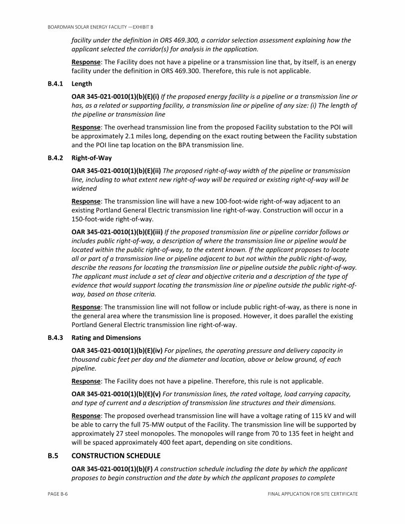
B.4.1 Length
OAR 345-021-0010(1)(b)(E)(i) If the proposed energy facility is a pipeline or a transmission line or has, as a related or supporting facility, a transmission line or pipeline of any size: (i) The length of the pipeline or transmission line
Response: The overhead transmission line from the proposed Facility substation to the POI will be approximately 2.1 miles long, depending on the exact routing between the Facility substation and the POI line tap location on the BPA transmission line.
B.4.2 Right-of-Way
OAR 345-021-0010(1)(b)(E)(ii) The proposed right-of-way width of the pipeline or transmission line, including to what extent new right-of-way will be required or existing right-of-way will be widened
Response: The transmission line will have a new 100-foot-wide right-of-way adjacent to an existing Portland General Electric transmission line right-of-way. Construction will occur in a 150-foot-wide right-of-way.
OAR 345-021-0010(1)(b)(E)(iii) If the proposed transmission line or pipeline corridor follows or includes public right-of-way, a description of where the transmission line or pipeline would be located within the public right-of-way, to the extent known. If the applicant proposes to locate all or part of a transmission line or pipeline adjacent to but not within the public right-of-way, describe the reasons for locating the transmission line or pipeline outside the public right-of-way. The applicant must include a set of clear and objective criteria and a description of the type of evidence that would support locating the transmission line or pipeline outside the public right-of-way, based on those criteria.
Response: The transmission line will not follow or include public right-of-way, as there is none in the general area where the transmission line is proposed. However, it does parallel the existing Portland General Electric transmission line right-of-way.
B.4.3 Rating and Dimensions
OAR 345-021-0010(1)(b)(E)(iv) For pipelines, the operating pressure and delivery capacity in thousand cubic feet per day and the diameter and location, above or below ground, of each pipeline.
Response: The Facility does not have a pipeline. Therefore, this rule is not applicable.
OAR 345-021-0010(1)(b)(E)(v) For transmission lines, the rated voltage, load carrying capacity, and type of current and a description of transmission line structures and their dimensions.
Response: The proposed overhead transmission line will have a voltage rating of 115 kV and will be able to carry the full 75-MW output of the Facility. The transmission line will be supported by approximately 27 steel monopoles. The monopoles will range from 70 to 135 feet in height and will be spaced approximately 400 feet apart, depending on site conditions.
B.5 CONSTRUCTION SCHEDULE
OAR 345-021-0010(1)(b)(F) A construction schedule including the date by which the applicant proposes to begin construction and the date by which the applicant proposes to complete

BOARDMAN SOLAR ENERGY FACILITY—EXHIBIT B
FINAL APPLICATION FOR SITE CERTIFICATE PAGE B-7
construction. Construction is defined in OAR 345-001-0010. The applicant shall describe in this exhibit all work on the site that the applicant intends to begin before the Council issues a site certificate. The applicant shall include an estimate of the cost of that work. For the purpose of this exhibit, “work on the site” means any work within a site or corridor, that the applicant anticipates or has performed as of the time of submitting the application.
The Applicant proposes to begin construction by October 1, 2018, and complete construction by December 31, 2019. These 15 months constitute the entire construction period as construction is defined by OAR 345-001-0010, but site work will not occur during the entire time. Heavy construction vehicles will be onsite starting in January to largely complete work within 9 months. Peak construction activity, during which most component delivery and installation will occur, will likely begin in March and end within 4 to 6 months.
The following activities have been completed, or will be completed, before the Council issues a site certificate:
• Geotechnical survey
• Cultural survey
• American Land Title Association survey
• Preliminary design
• Wetland survey
• Solar monitoring station installation
• Habitat characterization
• Rare plant survey
• Avian survey
• Raptor nest survey
• Washington ground squirrel survey
• Interconnection studies
• Land lease
The estimated cost of this work is under $250,000, in accordance with ORS 469.300(4) and OAR 345-001-0010(11).

Figures

FIGURE B-1Vicinity MapBoardman Solar Energy Facility Application for Site CertificateMorrow and Gilliam Counties, Oregon
BAOTSP01 C:\GIS\PROJ\INVENERGY\421524HEPPNER\BOARDMAN_SOLAR_PROJECT\GIS\MAPFILES\2017\JANUARY\FIGURE_B-1_VICINITY_MAP.MXD CARCHER 1/9/2017 1:16:48 PM
VICINITY MAP
AlpineAlpine
ArlingtonArlington
BarnettBarnett
BoardmanBoardman BoardmanBoardmanJunctionJunction
CecilCecilEllaElla
IoneIone
IrrigonIrrigon
JordanJordan
LexingtonLexington
McDonaldMcDonald
MessnerMessner
MikkaloMikkalo
MorganMorgan
OlexOlex
PatersonPatersonJunctionJunction
QuintonQuinton
Rock CreekRock CreekSand HollowSand Hollow
ShutlerShutler
StrawberryStrawberry
AlderdaleAlderdale
BickletonBickleton
ClevelandCleveland
DotDot
Goodnoe HillsGoodnoe Hills
PatersonPaterson
RooseveltRooseveltSundaleSundale
WhitcombWhitcomb
§̈¦84
§̈¦84
£¤730
ST74
ST221
ST14
ST19
ST206
ST207
OREGON
WASHINGTON
SHERMANCounty
SHERMANCounty
SHERMANCounty
GILLIAMCounty
MORROWCounty
KLICKITATCounty
BENTONCounty
YAKIMACounty
John Da y River
Rhea
Cree
k
Glade C reek
Grass Valle
y Can
yon
Willow Creek
Rock
Cre e kMule D ry Creek
Ea stBra
nchGlad
eCr e
ek
Wood G ulch
Rock Creek
Ei g htmile
Canyon
Sixmile Cany on
Pine Creek
Alder Creek
0 7Miles$
Facility Location
LEGENDFacility Site Boundary
!( CityMajor HighwayHighwayMajor RoadLocal RoadCreekWaterCounty BoundaryState Boundary
Service Layer Credits: Sources: Esri, HERE,DeLorme, Intermap, increment P Corp.,GEBCO, USGS, FAO, NPS, NRCAN,GeoBase, IGN, Kadaster NL, Ordnance Survey,Esri Japan, METI, Esri China (Hong Kong),swisstopo, MapmyIndia, © OpenStreetMapcontributors, and the GIS User CommunitySources: Esri, USGS, NOAAContent may not reflect National Geographic'scurrent map policy. Sources: NationalGeographic, Esri, DeLorme, HERE, UNEP-WCMC, USGS, NASA, ESA, METI, NRCAN,GEBCO, NOAA, increment P Corp.

Modules in racking
Post
Module cable string
Cable between combiner boxes
Figure B-2.Example of Module Block ComponentsBoardman Solar Energy Facility, Morrow and Gilliam Counties, Oregon
Service road Inverter
Transformer
Concrete pad
Tracker arm and motor box
Junction box

BOARDMAN SOLAR ENERGY FACILITY—EXHIBIT C
FINAL APPLICATION FOR SITE CERTIFICATE PAGE C-I
EXHIBIT C FACILITY LOCATION OAR 345-021-0010(1)(c)
TABLE OF CONTENTS
C.1 MAPS ............................................................................................................................................. C-1
C.2 LOCATION AND DISTURBANCE AREAS .......................................................................................... C-1
C.3 RELATION TO OTHER ENERGY GENERATION FACILITIES............................................................... C-2
TABLE
C-1 TEMPORARY AND PERMANENT DISTURBANCE BY COUNTY ........................................................ C-2
FIGURES
C-1 Facility LayoutC-2 Facility Layout DetailsC-3 Other Permitted Energy Generation Facilities

BOARDMAN SOLAR ENERGY FACILITY—EXHIBIT C
FINAL APPLICATION FOR SITE CERTIFICATE PAGE C-1
OAR 345-021-0010(1)(c) Information about the location of the proposed facility, including:
C.1 MAPS
OAR 345-021-0010(1)(c)(A) A map or maps showing the proposed locations of the energy facility site, all related or supporting facility sites and all areas that might be temporarily disturbed during construction of the facility in relation to major roads, water bodies, cities and towns, important landmarks and topographic features, using a scale of 1 inch = 2000 feet or smaller when necessary to show detail.
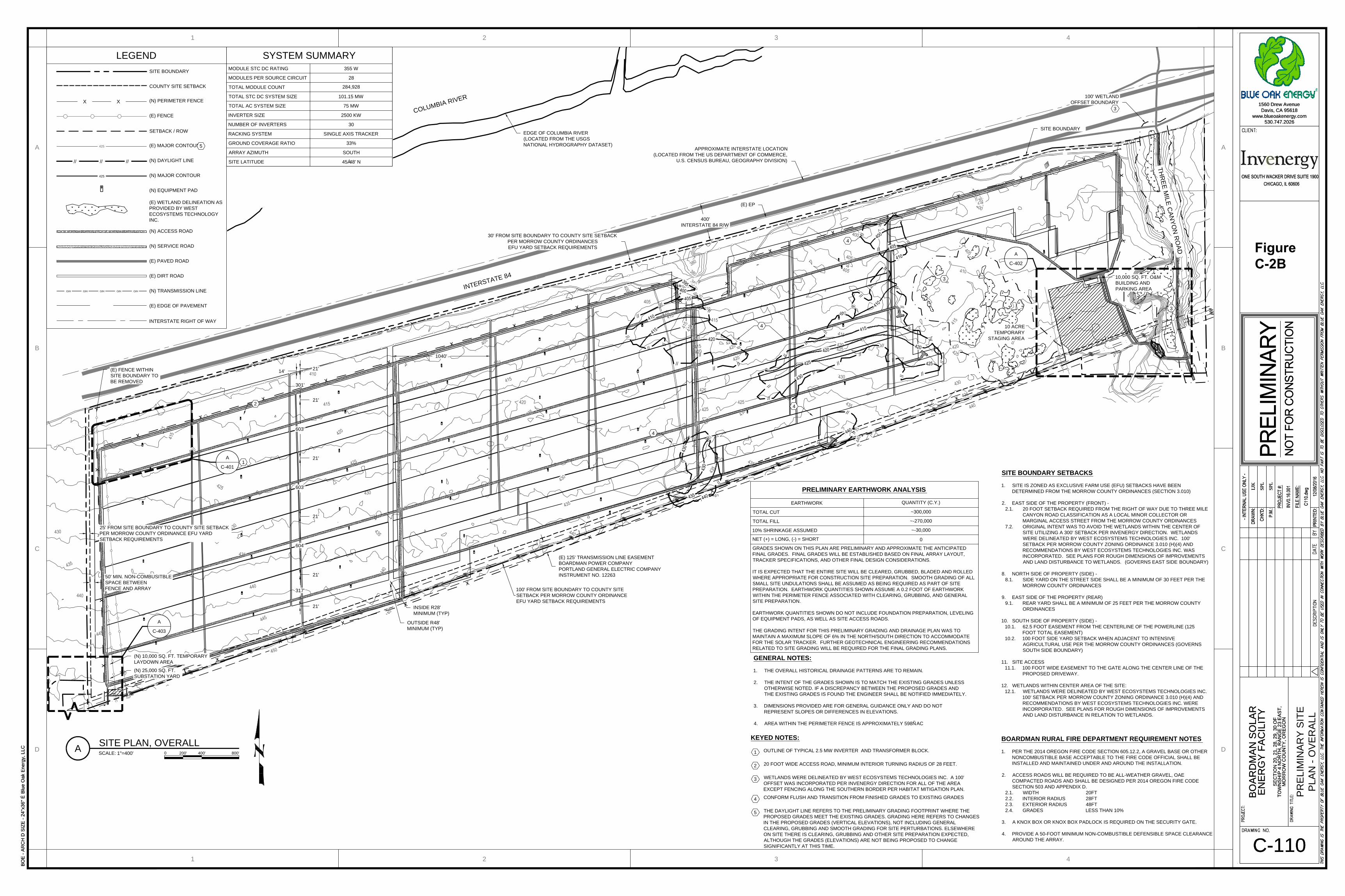
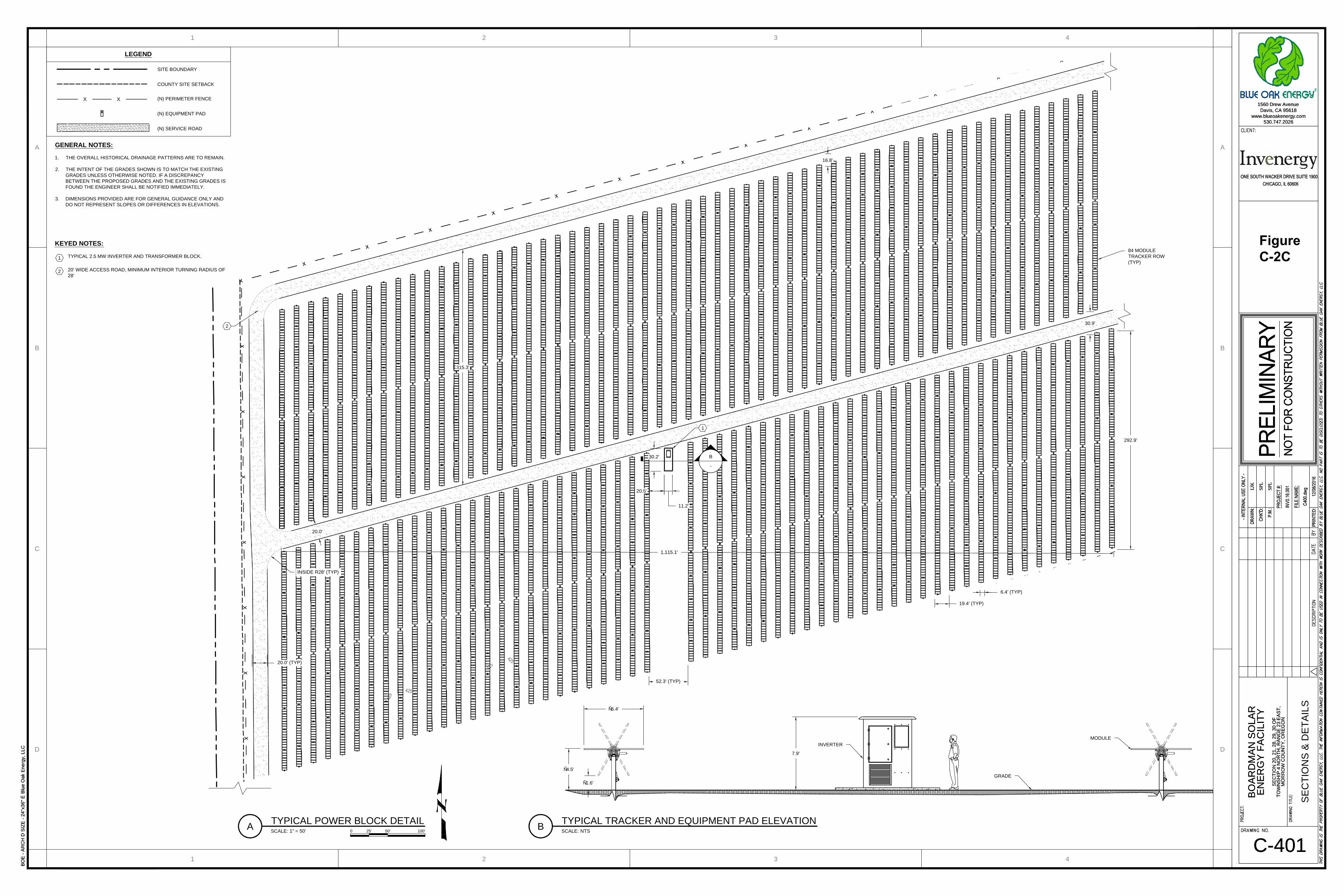
Response: Figure C-1 (Facility Layout) shows the proposed location of the Boardman Solar Energy Facility (Facility), related or supporting facilities, and temporary disturbance areas using a scale of 1 inch = 2,000 feet. Figure C-2 (Facility Layout Details, consisting of five sheets) provides additional detail. Figure C-2A shows the vicinity and provides the abbreviations that are used in Figures C-2B through C-2E. Figure C-2B shows the proposed facilities in Morrow County. Figure C-2C shows a close-up of one solar module block. Figure C-2D shows the site access. Figure C-2E shows the transmission line corridor.
C.2 LOCATION AND DISTURBANCE AREAS
OAR 345-021-0010(1)(c)(B) A description of the location of the proposed energy facility site, the proposed site of each related or supporting facility and areas of temporary disturbance, including the total land area (in acres) within the proposed site boundary, the total area of permanent disturbance, and the total area of temporary disturbance. If a proposed pipeline or transmission line is to follow an existing road, pipeline or transmission line, the applicant shall state to which side of the existing road, pipeline or transmission line the proposed facility will run, to the extent this is known.
Response: The Facility will be located south of Interstate 84 approximately twelve miles east of Arlington and twelve miles west of Boardman.
All Facility components with the exception of the proposed transmission line will be located in Morrow County, Oregon, in the following sections:
• Township 4 North, Range 23E, Sections 20, 21, 28, 29, 30, 31
The proposed transmission line will be located in Gilliam County, Oregon, in the following sections:
• Township 4 North, Range 22E, Sections 25, 36
• Township 3 North, Range 22E, Sections 1, 12
The proposed transmission line will run parallel to and immediately west of an existing Portland General Electric transmission line.
The Facility site boundary covers approximately 798 acres and encompasses the solar module blocks, collection system, generator step-up transformer and substation, 115-kilovolt transmission line, point of interconnection line tap, control house, operations and maintenance building, a main access road, internal service roads and gates, temporary staging areas, and a temporary concrete batch plant. For the purpose of analyzing potential impacts to resources, Boardman Solar Energy LLC (Applicant) has defined analysis areas based on this site boundary, consistent with OAR 345-001-0010(2) and (59). The analysis areas are identified in each relevant Exhibit (for example, in Exhibit J, Wetlands, and Exhibit P, Fish and Wildlife Habitats and Species). The acres potentially impacted within the site boundary during construction and operation are reflected in Table C-1. The Applicant requests flexibility in the final orientation of

BOARDMAN SOLAR ENERGY FACILITY —EXHIBIT C
PAGE C-2 FINAL APPLICATION FOR SITE CERTIFICATE
Facility components within the site boundary during final design before the start of construction provided the permanently and temporarily disturbed acres outlined below are not exceeded.
Table C-1 shows temporary and permanent disturbance numbers by county. The permanently disturbed acres represent impacts during construction that will remain during operations, and the temporarily disturbed acres represent additional impacts during construction. Temporarily disturbed acres will be restored following construction, and permanently disturbed acres will be restored following retirement.
Table C-1. Temporary and Permanent Disturbance by County
County Disturbance Type Permanently
Disturbed (acres) Temporarily
Disturbed (acres) Total Disturbed
(acres)
Morrow County
Solar module blocksa 453.00 5.93 458.93
Interior service roads 28.22 0 28.22
Perimeter fenceb 0.67 3.41 4.08
O&M building and parking 0.23 0 0.23
Substation (with control house) and staging area
0.57 0.23 0.80
Main staging area and batch plant
0 10.00 10.00
Access roadc 0.68 0.21 0.89
Gilliam County
Transmission line road 2.40 0 2.40
Transmission lined 0.02 38.98 39.00
POI line tap and staging area 0.23 0.23 0.46
Total 486.03 58.99 545.02
a Solar module blocks assume the entire block will be cleared for construction and therefore permanently disturbed, even though the ground-coverage ratio is only 33 percent. An additional approximate 6 acres are assumed to be temporarily disturbed for grading during construction.
b Perimeter fence assumes approximately 1.4 acres for temporarily disturbed impacts for grading plus about 2 acres (29,275.5 feet by 3 feet) for other construction-related impacts during fence installation.
c Access road impacts include the entire 1,500-foot length, even though 600 feet of this is an existing 8-foot-wide road that will be widened and improved. Temporary disturbance is for grading the ascent.
d Transmission line right-of-way assumes 27 3-foot-radius poles for permanent disturbance and the entire 150-foot-wide construction right-of-way for temporary disturbance.
C.3 RELATION TO OTHER ENERGY GENERATION FACILITIES
OAR 345-021-0010(1)(c)(C) For energy generation facilities, a map showing the approximate locations of any other energy generation facilities that are known to the applicant to be permitted at the state or local level within the study area as defined in OAR 345-001-0010 for impacts to local services.
Response: Figure C-3 shows the proposed location of the Facility in relation to other energy generation facilities within 10 miles.

Figures

T 0 4 N - R 2 3 E
T 0 3 N - R 2 3 E
T0
4N
-R2
2E
T0
3N
-R2
2E
3632
09
28
0501
2019 21
33
29
31
12
30
08
06
04
07
25
ThreeMi le Can yonRd
Columbia River HwyColumbia River Hwy
£¤30 £¤30
£¤30§̈¦84
Pa
cif iCo
rp
BonnevillePower Administration
Portland General Electric Co
Figure C-1. Facility LayoutBoardman Solar Energy Facility, Morrow and Gilliam Counties, Oregon
Date Saved: Friday, December 16, 2016 3:15:30 PM Prepared By: KHanusiak Coordinate System: NAD 1983 UTM Zone 11N Path: \\Arcgis-db\D\_MXDs\US\OR\_Solar\Broadman\boardman_site_cert_c1.mxd
LegendFacility Perimeter FenceFacility Temporary GradingConstruction AreaFacility SubstationFacility O&M BuildingFacility POI Line TapFacility Temporary Staging AreaFacility Access RoadFacility Service RoadFacility Transmission LineFacility Site BoundaryFacility Inverter and TransformerPadsFacility Module BlocksTownship BoundarySection Line
December 19, 2016Rev. 00
£730
G i l l i a mM o r r o w
B e n t o n
K l i c k i t a t
Ya k i m a
§̈¦8484
!(
ÛÛÛ
1,000 0 1,000Feet
1 inch = 2,000 feet

TIT
LE
S
HE
ET
LJK
SPL
SPL
BOE - ARCH D SIZE - 24"x36" É Blue Oak Energy, LLC
C-001
È
1560 Drew Avenue
Davis, CA 95618
www.blueoakenergy.com
530.747.2026
BO
AR
DM
AN
S
OL
AR
EN
ER
GY
F
AC
IL
IT
Y
SE
CT
IO
N 2
0, 2
1, 2
8, 2
9, 3
0 O
F
TO
WN
SH
IP
4
N
OR
TH
, R
AN
GE
2
3 E
AS
T,
MO
RR
OW
C
OU
NT
Y, O
RE
GO
N
ASTORIA
SALEM
EUGENE
ASHLAND
PORTLAND
BEND
BOARDMAN
DRAWING INDEX:
DWG NO. TITLE REV NO.
C-001 TITLE SHEET
C-110 PRELIMINARY SITE PLAN - OVERALL
C-401 SECTIONS & DETAILS
C-402 SITE ACCESS PLAN & DETAILS
C-403 TRANSMISSION LINE CORRIDOR
PRELIMINARY DESIGN PLANS
BOARDMAN SOLAR ENERGY FACILITY
SECTIONS 1, 12, 20, 21, 25, 28, 29, 30, 31, AND 36 TOWNSHIP 4 NORTH, RANGE 23 EAST MORROW AND GILLIAM COUNTIES, OR
PROJECT LOCATION: PROJECT SCOPE:
SOLAR ELECTRIC SYSTEM
THE PROJECT ENTAILS THE INSTALLATION OF A SOLAR PHOTOVOLTAIC SYSTEM NEAR BOARDMAN, MORROW
COUNTY, OREGON.
THE INSTALLATION CONSISTS OF NEW GROUND MOUNTED STRUCTURES WITH MOUNTED PHOTOVOLTAICS.
SITE INFORMATION:
VICINITY MAP:
ZONING:
EFFECTIVE FARM USE (EFU)
ACREAGE:
SITE BOUNDARY AREA: 798Ñ ACRES
CONTACT:
TEL:
OWNER/SITE CONTACT
INVENERGY SOLAR DEVELOPMENT, LLC
ONE SOUTH WACKER DRIVE, SUITE 1800
CHICAGO, IL 60606
LAURA MINER
(503) 964-8900
CONTACT:
TEL:
DESIGN ENGINEERING FIRM/CIVIL ENGINEER
BLUE OAK ENERGY
1560 DREW AVENUE
DAVIS, CA 95618
SAMUEL P. LAUGHLIN, PE
(530) 747-2026
OR PE LIC. # 90509
PROJECT SITE
STANDARDS AND CONDITIONS:
THESE PRELIMINARY GRADING AND DRAINAGE PLANS SHALL CONFORM TO THE FOLLOWING CODE VERSIONS:
1. 2012 INTERNATIONAL BUILDING CODE
2. ASCE 7-10: MINIMUM DESIGN LOADS FOR BUILDINGS AND OTHER STRUCTURES
3. 2014 OREGON FIRE CODE
4. STATE OF OREGON DEPARTMENT OF TRANSPORTATION (ODOT) STANDARD PLANS AND SPECIFICATIONS,
LATEST EDITION
AERIAL MAP:
PROJECT TEAM:
SITE BOUNDARY
ABBREVIATIONS:
AB AGGREGATE BASE
AC ASPHALT CONCRETE
APPROX APPROXIMATE
AVE AVERAGE
BSL BUILDING SETBACK LINE
BLDG BUILDING
BMP
BEST MANAGEMENT
PRACTICE
C/L CENTERLINE
CB CATCH BASIN
CONC CONCRETE
CP CONTROL POINT
DI DRAIN INLET
EFU EFFECTIVE FARM USE
EG EXISTING GRADE
EP EDGE OF PAVEMENT
ELEC ELECTRICAL
ESCP
EROSION AND
SEDIMENTATION CONTROL
PLAN
ETW EDGE OF TRAVELED WAY
(E)
EXISTING
FD FOUND
FG FINISHED GRADE
FH FIRE HYDRANT
FL FLOW LINE
FR FIBER ROLL
FS FINISHED SURFACE
GB GRADE BREAK
GPR
GROUND PENETRATING
RADAR
GV GAS VALVE
HP HOSE PIPE
HT HEIGHT
ID IDENTIFICATION
IRRIG IRRIGATION
JP JOINT POLE
LP LIGHT POLE
MAX MAXIMUM
MB MAILBOX
MH MAN HOLE
MIN MINIMUM
(N)
NEW
O/HOVERHEAD LINE
OAE OR APPROVED EQUIVALENT
ODEQ
OREGON DEPARTMENT OF
ENVIRONMENTAL QUALITY
ODOT
OREGON DEPARTMENT OF
TRANSPORTATION
P PAVEMENT
P/L PROPERTY LINE
PP POWER POLE
R RADIUS
RR RAIL ROAD TIES
R/W RIGHT-OF-WAY
SCS
SOIL CONSERVATION
SERVICE
SD STORM DRAIN
SF SILT FENCE
SNF
INDICATES SEARCHED
FOUND NOTHING
SP SERVICE POLE
SPT SPOT ELEVATION
SS SANITARY SEWER
TC TOP OF CURB
TYP TYPICAL
WV WATER VALVE
DEVELOPER
SITE BOUNDARY
LJK
SPL
SPL
BOE - ARCH D SIZE - 24"x36" É Blue Oak Energy, LLC
C-001
È
1560 Drew Avenue
Davis, CA 95618
www.blueoakenergy.com
530.747.2026
BO
AR
DM
AN
S
OL
AR
EN
ER
GY
F
AC
IL
IT
Y
SE
CT
IO
N 2
0, 2
1, 2
8, 2
9, 3
0 O
F
TO
WN
SH
IP
4
N
OR
TH
, R
AN
GE
2
3 E
AS
T,
MO
RR
OW
C
OU
NT
Y, O
RE
GO
NFigure C-2A. Facility Layout DetailsBoardman Solar Energy Facility Application for Site CertificateMorrow and Gilliam Counties, Oregon
O/H
O/H
X
X
X
X
X
X
X
X
X
X
X
X
X
X
X
X
X
X
X
X
X
X
X
X
X
X
X
X
X
X
X
X
X
X
X
X
X
X
X
X
X
O/H
O/H
X
X
X
X
X
X
X
X
X
X
X
X
X
X
X
X
X
X
X
X
X
X
X
X
X
X
X
X
X
X
X
X
X
X
X
X
X
X
X
X
X
D
1
C
B
A
2 3 4
1 2 3 4
D
C
B
A
PR
EL
IM
IN
AR
Y S
IT
E
PL
AN
- O
VE
RA
LL
LJK
SPL
SPL
BOE - ARCH D SIZE - 24"x36" É Blue Oak Energy, LLC
C-110
È
1560 Drew Avenue
Davis, CA 95618
www.blueoakenergy.com
530.747.2026
BO
AR
DM
AN
S
OL
AR
EN
ER
GY
F
AC
IL
IT
Y
SE
CT
IO
N 2
0, 2
1, 2
8, 2
9, 3
0 O
F
TO
WN
SH
IP
4
N
OR
TH
, R
AN
GE
2
3 E
AS
T,
MO
RR
OW
C
OU
NT
Y, O
RE
GO
N
LJK
SPL
SPL
BOE - ARCH D SIZE - 24"x36" É Blue Oak Energy, LLC
C-110
È
1560 Drew Avenue
Davis, CA 95618
www.blueoakenergy.com
530.747.2026
BO
AR
DM
AN
S
OL
AR
EN
ER
GY
F
AC
IL
IT
Y
SE
CT
IO
N 2
0, 2
1, 2
8, 2
9, 3
0 O
F
TO
WN
SH
IP
4
N
OR
TH
, R
AN
GE
2
3 E
AS
T,
MO
RR
OW
C
OU
NT
Y, O
RE
GO
N
IN
T
E
R
S
T
A
T
E
8
4
C
O
L
U
M
B
IA
R
IV
E
R
SCALE:800'0 400'200'
A
SITE PLAN, OVERALL
1"=400'
A
C-401
GENERAL NOTES:
1. THE OVERALL HISTORICAL DRAINAGE PATTERNS ARE TO REMAIN.
2. THE INTENT OF THE GRADES SHOWN IS TO MATCH THE EXISTING GRADES UNLESS
OTHERWISE NOTED. IF A DISCREPANCY BETWEEN THE PROPOSED GRADES AND
THE EXISTING GRADES IS FOUND THE ENGINEER SHALL BE NOTIFIED IMMEDIATELY.
3. DIMENSIONS PROVIDED ARE FOR GENERAL GUIDANCE ONLY AND DO NOT
REPRESENT SLOPES OR DIFFERENCES IN ELEVATIONS.
4. AREA WITHIN THE PERIMETER FENCE IS APPROXIMATELY 598Ñ AC
KEYED NOTES:
OUTLINE OF TYPICAL 2.5 MW INVERTER AND TRANSFORMER BLOCK.
20 FOOT WIDE ACCESS ROAD, MINIMUM INTERIOR TURNING RADIUS OF 28 FEET.
WETLANDS WERE DELINEATED BY WEST ECOSYSTEMS TECHNOLOGIES INC. A 100'
OFFSET WAS INCORPORATED PER INVENERGY DIRECTION FOR ALL OF THE AREA
EXCEPT FENCING ALONG THE SOUTHERN BORDER PER HABITAT MITIGATION PLAN.
CONFORM FLUSH AND TRANSITION FROM FINISHED GRADES TO EXISTING GRADES
THE DAYLIGHT LINE REFERS TO THE PRELIMINARY GRADING FOOTPRINT WHERE THE
PROPOSED GRADES MEET THE EXISTING GRADES. GRADING HERE REFERS TO CHANGES
IN THE PROPOSED GRADES (VERTICAL ELEVATIONS), NOT INCLUDING GENERAL
CLEARING, GRUBBING AND SMOOTH GRADING FOR SITE PERTURBATIONS. ELSEWHERE
ON SITE THERE IS CLEARING, GRUBBING AND OTHER SITE PREPARATION EXPECTED,
ALTHOUGH THE GRADES (ELEVATIONS) ARE NOT BEING PROPOSED TO CHANGE
SIGNIFICANTLY AT THIS TIME.
1
2
3
4
5
LEGEND
SITE BOUNDARY
COUNTY SITE SETBACK
(N) PERIMETER FENCE
(E) FENCE
SETBACK / ROW
(E) MAJOR CONTOUR
(N) DAYLIGHT LINE
(N) MAJOR CONTOUR
(N) EQUIPMENT PAD
(E) WETLAND DELINEATION AS
PROVIDED BY WEST
ECOSYSTEMS TECHNOLOGY
INC.
(N) ACCESS ROAD
(N) SERVICE ROAD
(E) PAVED ROAD
(E) DIRT ROAD
(N) TRANSMISSION LINE
(E) EDGE OF PAVEMENT
INTERSTATE RIGHT OF WAY
X X
21'
14'
301'
21'
603'
21'
603'
21'
604'
21'
317'
21'
1
2
3
// // //
425
BOARDMAN RURAL FIRE DEPARTMENT REQUIREMENT NOTES
1. PER THE 2014 OREGON FIRE CODE SECTION 605.12.2, A GRAVEL BASE OR OTHER
NONCOMBUSTIBLE BASE ACCEPTABLE TO THE FIRE CODE OFFICIAL SHALL BE
INSTALLED AND MAINTAINED UNDER AND AROUND THE INSTALLATION.
2. ACCESS ROADS WILL BE REQUIRED TO BE ALL-WEATHER GRAVEL, OAE
COMPACTED ROADS AND SHALL BE DESIGNED PER 2014 OREGON FIRE CODE
SECTION 503 AND APPENDIX D.
2.1. WIDTH 20FT
2.2. INTERIOR RADIUS 28FT
2.3. EXTERIOR RADIUS 48FT
2.4. GRADES LESS THAN 10%
3. A KNOX BOX OR KNOX BOX PADLOCK IS REQUIRED ON THE SECURITY GATE.
4. PROVIDE A 50-FOOT MINIMUM NON-COMBUSTIBLE DEFENSIBLE SPACE CLEARANCE
AROUND THE ARRAY.
A
C-402
INSIDE R28'
MINIMUM (TYP)
OUTSIDE R48'
MINIMUM (TYP)
425
400'
INTERSTATE 84 R/W
(E) 125' TRANSMISSION LINE EASEMENT
BOARDMAN POWER COMPANY
PORTLAND GENERAL ELECTRIC COMPANY
INSTRUMENT NO. 12263
(E) EP
SITE BOUNDARY SETBACKS
1. SITE IS ZONED AS EXCLUSIVE FARM USE (EFU) SETBACKS HAVE BEEN
DETERMINED FROM THE MORROW COUNTY ORDINANCES (SECTION 3.010)
2. EAST SIDE OF THE PROPERTY (FRONT) -
2.1. 20 FOOT SETBACK REQUIRED FROM THE RIGHT OF WAY DUE TO THREE MILE
CANYON ROAD CLASSIFICATION AS A LOCAL MINOR COLLECTOR OR
MARGINAL ACCESS STREET FROM THE MORROW COUNTY ORDINANCES
7.2. ORIGINAL INTENT WAS TO AVOID THE WETLANDS WITHIN THE CENTER OF
SITE UTILIZING A 300' SETBACK PER INVENERGY DIRECTION. WETLANDS
WERE DELINEATED BY WEST ECOSYSTEMS TECHNOLOGIES INC. 100'
SETBACK PER MORROW COUNTY ZONING ORDINANCE 3.010 (H)(4) AND
RECOMMENDATIONS BY WEST ECOSYSTEMS TECHNOLOGIES INC. WAS
INCORPORATED. SEE PLANS FOR ROUGH DIMENSIONS OF IMPROVEMENTS
AND LAND DISTURBANCE TO WETLANDS. (GOVERNS EAST SIDE BOUNDARY)
8. NORTH SIDE OF PROPERTY (SIDE) -
8.1. SIDE YARD ON THE STREET SIDE SHALL BE A MINIMUM OF 30 FEET PER THE
MORROW COUNTY ORDINANCES
9. EAST SIDE OF THE PROPERTY (REAR)
9.1. REAR YARD SHALL BE A MINIMUM OF 25 FEET PER THE MORROW COUNTY
ORDINANCES
10. SOUTH SIDE OF PROPERTY (SIDE) -
10.1. 62.5 FOOT EASEMENT FROM THE CENTERLINE OF THE POWERLINE (125
FOOT TOTAL EASEMENT)
10.2. 100 FOOT SIDE YARD SETBACK WHEN ADJACENT TO INTENSIVE
AGRICULTURAL USE PER THE MORROW COUNTY ORDINANCES (GOVERNS
SOUTH SIDE BOUNDARY)
11. SITE ACCESS
11.1. 100 FOOT WIDE EASEMENT TO THE GATE ALONG THE CENTER LINE OF THE
PROPOSED DRIVEWAY.
12. WETLANDS WITHIN CENTER AREA OF THE SITE:
12.1. WETLANDS WERE DELINEATED BY WEST ECOSYSTEMS TECHNOLOGIES INC.
100' SETBACK PER MORROW COUNTY ZONING ORDINANCE 3.010 (H)(4) AND
RECOMMENDATIONS BY WEST ECOSYSTEMS TECHNOLOGIES INC. WERE
INCORPORATED. SEE PLANS FOR ROUGH DIMENSIONS OF IMPROVEMENTS
AND LAND DISTURBANCE IN RELATION TO WETLANDS.
PRELIMINARY EARTHWORK ANALYSIS
EARTHWORK
QUANTITY (C.Y.)
TOTAL CUT~300,000
TOTAL FILL~-270,000
10% SHRINKAGE ASSUMED~-30,000
NET (+) = LONG, (-) = SHORT
0
GRADES SHOWN ON THIS PLAN ARE PRELIMINARY AND APPROXIMATE THE ANTICIPATED
FINAL GRADES. FINAL GRADES WILL BE ESTABLISHED BASED ON FINAL ARRAY LAYOUT,
TRACKER SPECIFICATIONS, AND OTHER FINAL DESIGN CONSIDERATIONS.
IT IS EXPECTED THAT THE ENTIRE SITE WILL BE CLEARED, GRUBBED, BLADED AND ROLLED
WHERE APPROPRIATE FOR CONSTRUCTION SITE PREPARATION. SMOOTH GRADING OF ALL
SMALL SITE UNDULATIONS SHALL BE ASSUMED AS BEING REQUIRED AS PART OF SITE
PREPARATION. EARTHWORK QUANTITIES SHOWN ASSUME A 0.2 FOOT OF EARTHWORK
WITHIN THE PERIMETER FENCE ASSOCIATED WITH CLEARING, GRUBBING, AND GENERAL
SITE PREPARATION.
EARTHWORK QUANTITIES SHOWN DO NOT INCLUDE FOUNDATION PREPARATION, LEVELING
OF EQUIPMENT PADS, AS WELL AS SITE ACCESS ROADS.
THE GRADING INTENT FOR THIS PRELIMINARY GRADING AND DRAINAGE PLAN WAS TO
MAINTAIN A MAXIMUM SLOPE OF 6% IN THE NORTH/SOUTH DIRECTION TO ACCOMMODATE
FOR THE SOLAR TRACKER. FURTHER GEOTECHNICAL ENGINEERING RECOMMENDATIONS
RELATED TO SITE GRADING WILL BE REQUIRED FOR THE FINAL GRADING PLANS.
100' FROM SITE BOUNDARY TO COUNTY SITE
SETBACK PER MORROW COUNTY ORDINANCE
EFU YARD SETBACK REQUIREMENTS
30' FROM SITE BOUNDARY TO COUNTY SITE SETBACK
PER MORROW COUNTY ORDINANCES
EFU YARD SETBACK REQUIREMENTS
25' FROM SITE BOUNDARY TO COUNTY SITE SETBACK
PER MORROW COUNTY ORDINANCE EFU YARD
SETBACK REQUIREMENTS
10 ACRE
TEMPORARY
STAGING AREA
10,000 SQ. FT. O&M
BUILDING AND
PARKING AREA
(N) 25,000 SQ. FT.
SUBSTATION YARD
O/H O/H O/H O/H O/H
SITE BOUNDARY
(E) FENCE WITHIN
SITE BOUNDARY TO
BE REMOVED
T
H
R
E
E
M
IL
E
C
A
N
Y
O
N
R
O
A
D
A
C-403
4
4
4
4
1040'
SYSTEM SUMMARY
MODULE STC DC RATING 355 W
MODULES PER SOURCE CIRCUIT 28
TOTAL MODULE COUNT284,928
TOTAL STC DC SYSTEM SIZE 101.15 MW
TOTAL AC SYSTEM SIZE 75 MW
INVERTER SIZE 2500 KW
NUMBER OF INVERTERS 30
RACKING SYSTEM SINGLE AXIS TRACKER
GROUND COVERAGE RATIO 33%
ARRAY AZIMUTH SOUTH
SITE LATITUDE 45Á48' N
EDGE OF COLUMBIA RIVER
(LOCATED FROM THE USGS
NATIONAL HYDROGRAPHY DATASET)
3
50' MIN. NON-COMBUSITBLE
SPACE BETWEEN
FENCE AND ARRAY
100' WETLAND
OFFSET BOUNDARY
APPROXIMATE INTERSTATE LOCATION
(LOCATED FROM THE US DEPARTMENT OF COMMERCE,
U.S. CENSUS BUREAU, GEOGRAPHY DIVISION)
5
(N) 10,000 SQ. FT. TEMPORARY
LAYDOWN AREA
3
Figure C-2B
X
X
X
X
X
X
X
X
X
X
X
X
X
X
X
X
X
X
X
X
X
X
X
X
X
X
X
X
X
X
X
X
X
X
X
X
X
X
X
X
X
X
SE
CT
IO
NS
&
D
ET
AIL
S
D
1
C
B
A
2 3 4
1 2 3 4
D
C
B
A
LJK
SPL
SPL
BOE - ARCH D SIZE - 24"x36" É Blue Oak Energy, LLC
C-401
È
1560 Drew Avenue
Davis, CA 95618
www.blueoakenergy.com
530.747.2026
BO
AR
DM
AN
S
OL
AR
EN
ER
GY
F
AC
IL
IT
Y
SE
CT
IO
N 2
0, 2
1, 2
8, 2
9, 3
0 O
F
TO
WN
SH
IP
4
N
OR
TH
, R
AN
GE
2
3 E
AS
T,
MO
RR
OW
C
OU
NT
Y, O
RE
GO
N
LJK
SPL
SPL
BOE - ARCH D SIZE - 24"x36" É Blue Oak Energy, LLC
C-401
È
1560 Drew Avenue
Davis, CA 95618
www.blueoakenergy.com
530.747.2026
BO
AR
DM
AN
S
OL
AR
EN
ER
GY
F
AC
IL
IT
Y
SE
CT
IO
N 2
0, 2
1, 2
8, 2
9, 3
0 O
F
TO
WN
SH
IP
4
N
OR
TH
, R
AN
GE
2
3 E
AS
T,
MO
RR
OW
C
OU
NT
Y, O
RE
GO
N
B
-
SCALE:100'0 50'25'
1" = 50'
A
TYPICAL POWER BLOCK DETAIL
SCALE: NTS
B
TYPICAL TRACKER AND EQUIPMENT PAD ELEVATION
KEYED NOTES:
TYPICAL 2.5 MW INVERTER AND TRANSFORMER BLOCK.
20' WIDE ACCESS ROAD, MINIMUM INTERIOR TURNING RADIUS OF
28'
1
2
LEGEND
SITE BOUNDARY
COUNTY SITE SETBACK
(N) PERIMETER FENCE
(N) EQUIPMENT PAD
(N) SERVICE ROAD
X X
Ñ6.4'
19.4' (TYP)
6.4' (TYP)
MODULE
GRADE
INVERTER
84 MODULE
TRACKER ROW
(TYP)
292.9'
2
1
INSIDE R28' (TYP)
30.9'
20.0' (TYP)
52.3' (TYP)
20.5'
Ñ4.5'
7.9'
11.2'
30.2'
16.8'
GENERAL NOTES:
1. THE OVERALL HISTORICAL DRAINAGE PATTERNS ARE TO REMAIN.
2. THE INTENT OF THE GRADES SHOWN IS TO MATCH THE EXISTING
GRADES UNLESS OTHERWISE NOTED. IF A DISCREPANCY
BETWEEN THE PROPOSED GRADES AND THE EXISTING GRADES IS
FOUND THE ENGINEER SHALL BE NOTIFIED IMMEDIATELY.
3. DIMENSIONS PROVIDED ARE FOR GENERAL GUIDANCE ONLY AND
DO NOT REPRESENT SLOPES OR DIFFERENCES IN ELEVATIONS.
1,115.1'
Ñ1.6'
315.3'
20.0'
Figure C-2C

20549
422.266
gw
X
X
X
X
X
X
X
X
X
X
X
X
X
X
X
X
X
X
X
X
X
X
X
X
X
X
X
X
X
X
LEGEND
SITE BOUNDARY
COUNTY SITE SETBACK
(N) PERIMETER FENCE
(E) FENCE
SETBACK / ROW
(E) MAJOR CONTOUR
(E) MINOR CONTOUR
(E) WETLAND DELINEATION
AS PROVIDED BY WEST
ECOSYSTEMS
TECHNOLOGY INC.
(N) ACCESS ROAD
(N) SERVICE ROAD
(E) PAVED ROAD
(E) DIRT ROAD
(E) POWERPOLE
(N) GATE
SIT
E A
CC
ES
S P
LA
N
D
1
C
B
A
2 3 4
1 2 3 4
D
C
B
A
LJK
SPL
SPL
BOE - ARCH D SIZE - 24"x36" É Blue Oak Energy, LLC
C-402
È
1560 Drew Avenue
Davis, CA 95618
www.blueoakenergy.com
530.747.2026
BO
AR
DM
AN
S
OL
AR
EN
ER
GY
F
AC
IL
IT
Y
SE
CT
IO
N 2
0, 2
1, 2
8, 2
9, 3
0 O
F
TO
WN
SH
IP
4
N
OR
TH
, R
AN
GE
2
3 E
AS
T,
MO
RR
OW
C
OU
NT
Y, O
RE
GO
N
LJK
SPL
SPL
BOE - ARCH D SIZE - 24"x36" É Blue Oak Energy, LLC
C-402
È
1560 Drew Avenue
Davis, CA 95618
www.blueoakenergy.com
530.747.2026
BO
AR
DM
AN
S
OL
AR
EN
ER
GY
F
AC
IL
IT
Y
SE
CT
IO
N 2
0, 2
1, 2
8, 2
9, 3
0 O
F
TO
WN
SH
IP
4
N
OR
TH
, R
AN
GE
2
3 E
AS
T,
MO
RR
OW
C
OU
NT
Y, O
RE
GO
N
SCALE: 1" = 100'200'0 100'50'
A
SITE ACCESS PLAN
X X
425
424
T
H
R
E
E
M
IL
E
C
A
N
Y
O
N
R
O
A
D
SITE ACCESS TO BE IMPROVED PER
MORROW COUNTY PUBLIC WORKS
DEPARTMENT STANDARD DRAWING
FOR ROAD APPROACH CONSTRUCTION
NO DISTURBANCE
IN THIS AREA
OUTSIDE R48'
MINIMUM (TYP)
INSIDE R28'
MINIMUM (TYP)
(E) 125.00' TRANSMISSION LINE EASEMENT
BOARDMAN POWER COMPANY
PORTLAND GENERAL ELECTRIC COMPANY
INSTRUMENT NO. 12263
100.00' COUNTY
SITE SETBACK
10 ACRE FACILITY
TEMPORARY
STAGING AREA
GENERAL NOTES:
1. THE OVERALL HISTORICAL DRAINAGE PATTERNS ARE TO REMAIN.
2. THE INTENT OF THE GRADES SHOWN IS TO MATCH THE EXISTING
GRADES UNLESS OTHERWISE NOTED. IF A DISCREPANCY
BETWEEN THE PROPOSED GRADES AND THE EXISTING GRADES IS
FOUND THE ENGINEER SHALL BE NOTIFIED IMMEDIATELY.
3. DIMENSIONS PROVIDED ARE FOR GENERAL GUIDANCE ONLY AND
DO NOT REPRESENT SLOPES OR DIFFERENCES IN ELEVATIONS.
(E) FENCE
10,000 SQ. FT. O&M
BUILDING AND
PARKING AREA
100'
TRANSITION POINT FROM 300'
WETLAND SETBACK TO 100'
WETLAND SETBACK
EARTHWORK REQUIRED TO GRADE ACCESS RAMP:
(1250 C.Y. APPROX.)
EARTHWORK REQUIRED FOR SITE ACCESS:
6 INCHES OF GRAVEL ASSUMED (550 C.Y. APPROX.)
12 INCHES OF COMPACTED SUBGRADE ASSUMED (1100 C.Y. APPROX.)
100'
108'
S
=
1
2
%
(E) DIRT ROAD
WILLOW CREEK WILDLIFE
AREA ACCESS ROAD
100'
20'
FROM THREE MILE CANYON ROAD TO THIS POINT
(N) ACCESS ROAD SHALL WIDEN AND IMPROVE THE
(E) WILLOW CREEK WILDLIFE AREA ACCESS ROAD
KEYED NOTE:
WETLANDS WERE DELINEATED BY WEST ECOSYSTEMS
TECHNOLOGIES INC. A 100' OFFSET WAS INCORPORATED PER
INVENERGY DIRECTION FOR ALL OF THE AREA EXCEPT FENCING
ALONG THE SOUTHERN BORDER PER HABITAT MITIGATION PLAN.
1
1
1
Figure C-2D

O/H
O/H
O/HO/HO/H
O/HO/HO/H
O/H
O/H
O/H
O/H
O/H
O/H
O/H
O/H
O/H
O/H
O/H
O/H
O/HO/H
O/HO/HO/HO/H
O/HO/HO/HO/H
O/HO/H
O/HO/HO/HO/H
O/HO/HO/HO/H
O/HO/HO/H
X
X
X
X
X
O/H
O/H
O/HO/HO/H
O/HO/HO/H
O/H
O/H
O/H
O/H
O/H
O/H
O/H
O/H
O/H
O/H
O/H
O/H
O/HO/H
O/HO/HO/HO/H
O/HO/HO/HO/H
O/HO/H
O/HO/HO/HO/H
O/HO/HO/HO/H
O/HO/HO/H
X
X
X
X
X
83
05
53
6.4
03
pp
-0
19
00
0
O/HO/H
O/HO/HO/HO/H
O/HO/HO/HO/HO/HO/HO/HO/HO/HO/HO/HO/HO/HO/HO/HO/HO/HO/HO/HO/HO/HO/HO/HO/HO/HO/H
O
/H
O
/H
O/H
O/H
O/H
O/H
O/H
O/H
O/H
O/HO/H
O/HO/HO/HO/H
O/HO/HO/HO/HO/HO/HO/HO/HO/HO/HO/HO/HO/HO/HO/HO/HO/HO/HO/HO/HO/HO/HO/HO/HO/HO/H
O
/H
O
/H
O/H
O/H
O/H
O/H
O/H
O/H
O/H
MA
TC
HL
IN
E
SE
E D
ET
AIL
B
B
EL
OW
TR
AN
SM
IS
SIO
N L
IN
E
CO
RR
ID
OR
D
1
C
B
A
2 3 4
1 2 3 4
D
C
B
A
LJK
SPL
SPL
BOE - ARCH D SIZE - 24"x36" É Blue Oak Energy, LLC
C-403
È
1560 Drew Avenue
Davis, CA 95618
www.blueoakenergy.com
530.747.2026
BO
AR
DM
AN
S
OL
AR
EN
ER
GY
F
AC
IL
IT
Y
SE
CT
IO
N 2
0, 2
1, 2
8, 2
9, 3
0 O
F
TO
WN
SH
IP
4
N
OR
TH
, R
AN
GE
2
3 E
AS
T,
MO
RR
OW
C
OU
NT
Y, O
RE
GO
N
LJK
SPL
SPL
BOE - ARCH D SIZE - 24"x36" É Blue Oak Energy, LLC
C-403
È
1560 Drew Avenue
Davis, CA 95618
www.blueoakenergy.com
530.747.2026
BO
AR
DM
AN
S
OL
AR
EN
ER
GY
F
AC
IL
IT
Y
SE
CT
IO
N 2
0, 2
1, 2
8, 2
9, 3
0 O
F
TO
WN
SH
IP
4
N
OR
TH
, R
AN
GE
2
3 E
AS
T,
MO
RR
OW
C
OU
NT
Y, O
RE
GO
N
GENERAL NOTES
1. THE OVERALL HISTORICAL DRAINAGE PATTERNS ARE TO REMAIN.
2. THE INTENT OF THE GRADES SHOWN IS TO MATCH THE EXISTING
GRADES UNLESS OTHERWISE NOTED. IF A DISCREPANCY
BETWEEN THE PROPOSED GRADES AND THE EXISTING GRADES IS
FOUND THE ENGINEER SHALL BE NOTIFIED IMMEDIATELY.
3. THE ENTIRE SITE SHALL BE CLEARED AND GRUBBED FOR
CONSTRUCTION SITE PREPARATION.
4. DIMENSIONS PROVIDED ARE FOR GENERAL GUIDANCE ONLY AND
DO NOT REPRESENT SLOPES OR DIFFERENCES IN ELEVATIONS.
LEGEND
SITE BOUNDARY
(E) PP
COUNTY SITE SETBACK
(E) TRANSMISSION LINE
(E) FENCE (N) TRANSMISSION LINE
SETBACK / ROW
(E) TRANSMISSION LINE
EASEMENT
(N) PERIMETER FENCE (E) DIRT ROAD
(E) MAJOR CONTOUR (N) SERVICE ROAD
(E) MINOR CONTOUR (N) GATE
(E) WETLAND DELINEATION
AS PROVIDED BY WEST
ECOSYSTEMS
TECHNOLOGY INC.
X X
425
424
SCALE:
A
TRANSMISSION LINE PLAN 1 OF 2
1"=200'
SCALE:
B
TRANSMISSION LINE PLAN 2 OF 2
1"=200'
(E) PP (TYP)
(E) DIRT ROAD
150.00' TRANSMISSION
LINE BOUNDARY AND TEMPORARY ROW
(E) 125.00' TRANSMISSION LINE EASEMENT
BOARDMAN POWER COMPANY
PORTLAND GENERAL ELECTRIC COMPANY
INSTRUMENT NO. 12263
(E) PP (TYP)
(E) WETLAND
(E) DIRT ROAD
150.00' TRANSMISSION
LINE BOUNDARY AND TEMPORARY ROW
(E) 125.00' TRANSMISSION LINE EASEMENT
BOARDMAN POWER COMPANY
PORTLAND GENERAL ELECTRIC COMPANY
INSTRUMENT NO. 12263
APPROX. ROUTE OF (N)
TRANSMISSION LINE
APPROX. ROUTE OF (N)
TRANSMISSION LINE
10,000 SQ. FT.
LINE TAP AREA
O/H O/H
KEYED NOTES
1. POWER POLE PLACEMENT IN THIS LOCATION TO AVOID (E) WETLANDS.1
1
10,000 SQ. FT. LINE
TAP TEMPORARY
LAYDOWN AREA
(N) 10.00' WIDE PERMANENT SERVICE ROAD
HAMMERHEAD
R=20.00' (TYP)
INSIDE R = 28.00' (TYP)
100.00'
100.00' PERMANENT ROW
(TO BE FILED AND
RECORDED BY INVENERGY)
100.00' PERMANENT ROW
(TO BE FILED AND
RECORDED BY INVENERGY)
(N) 10.00' WIDE PERMANENT SERVICE ROAD
(E) DIRT ROAD
INSIDE R = 28.00' (TYP)
(N) 25,000 SQ. FT.
SUBSTATION YARD
(N) 10,000 SQ. FT.
TEMPORARY LAYDOWN
AREA
EARTHWORK:
CUT: 6.64 C.Y.
NET: 3.02 C.Y. (CUT)
EARTHWORK:
CUT: 115.37 C.Y.
NET: 269.83 C.Y. (FILL)EARTHWORK:
CUT: 2.48 C.Y.
NET: 14.89 C.Y. (FILL)
Figure C-2E

FIGURE C-3Other Permitted Energy Generation FacilitiesBoardman Solar Energy Facility Application for Site CertificateMorrow and Gilliam Counties, Oregon
BAOTSP01 C:\GIS\PROJ\INVENERGY\421524HEPPNER\BOARDMAN_SOLAR_PROJECT\GIS\MAPFILES\2017\JANUARY\FIGURE_C3_OTHER_PERMITTED_ENERGY_GENERATION_FACILITIES.MXD CARCHER 1/9/2017 10:55:47 AM
VICINITY MAP
ArlingtonArlington
BoardmanBoardman
CecilCecil
EllaElla
MessnerMessner
ShutlerShutler
AlderdaleAlderdale
PatersonPaterson
RooseveltRoosevelt
WhitcombWhitcomb
ST74
ST19
§̈¦84
§̈¦84
ST14
Boardman Boardman AirportAirport
Gillia
m Co
unty
Morro
w Co
unty
Gilliam CountyKlickitat County
Morrow CountyKlickitat County
Klick
itat C
ounty
Bento
n Cou
nty
O r e g o nO r e g o n
W a s h i n g t o nW a s h i n g t o n
0 2.5Miles$
Facility Location
LEGENDFacility Site Boundary10 miles from Facility Site BoundaryWaterCity LimitState BoundaryCounty BoundaryBoardman Coal Plant and Carty Generating Station
Service Layer Credits: Sources: Esri,USGS, NOAAContent may not reflect NationalGeographic's current map policy.Sources: National Geographic, Esri,DeLorme, HERE, UNEP-WCMC,USGS, NASA, ESA, METI, NRCAN,GEBCO, NOAA, increment P Corp.
Wind Energy Generation FacilitiesPermitted
Horn ButteMontagueSaddle ButteThreemile Canyon
Permitted and OperationalLeaning Juniper IIALeaning Juniper IIBPebble SpringsShepherds Flat (Central)Shepherds Flat (North)Shepherds Flat (South)Willow Creek
Note: The site boundaries shown are based on the best publicly available maps and data.

BOARDMAN SOLAR ENERGY FACILITY—EXHIBIT D
FINAL APPLICATION FOR SITE CERTIFICATE PAGE D-I
EXHIBIT D APPLICANT’S ORGANIZATIONAL, MANAGERIAL, AND TECHNICAL EXPERTISE
OAR 345-021-0010(1)(d)
TABLE OF CONTENTS
Page
D.1 APPLICANT’S PREVIOUS EXPERIENCE .......................................................................................... D-1
D.2 QUALIFICATIONS OF APPLICANT’S PERSONNEL .......................................................................... D-2
D.3 QUALIFICATIONS OF KNOWN CONTRACTORS ............................................................................. D-3
D.4 APPLICANT’S PAST PERFORMANCE ............................................................................................. D-3
D.5 APPLICANT WITH NO PREVIOUS EXPERIENCE ............................................................................. D-3
D.6 ISO CERTIFIED PROGRAM ............................................................................................................ D-3
D.7 MITIGATION ................................................................................................................................. D-4
TABLE
D-1 Summary of Invenergy Solar Projects .......................................................................................... D-1

BOARDMAN SOLAR ENERGY FACILITY—EXHIBIT D
FINAL APPLICATION FOR SITE CERTIFICATE PAGE D-1
OAR 345-021-0010(1)(d) Information about the organizational expertise of the applicant to construct and operate the proposed facility, providing evidence to support a finding by the Council as required by OAR 345-022-0010, including:
D.1 APPLICANT’S PREVIOUS EXPERIENCE
(A) The applicant’s previous experience, if any, in constructing and operating similar facilities.
Response: Boardman Solar Energy LLC (Applicant) does not have any previous experience in constructing and operating similar facilities, but it is a wholly owned subsidiary of Invenergy Solar Development LLC. Invenergy Solar Development LLC is a wholly owned subsidiary of Invenergy LLC (Invenergy), an independently owned company that has experience with developing, constructing, owning, and operating power generation and energy storage facilities across North America and Europe.
Invenergy’s expertise comprises a range of fully integrated in-house capabilities, including project development, permitting, transmission, interconnection, energy marketing, finance, engineering, project construction, and operations and maintenance.
To date, Invenergy has developed more than 13,719 megawatts (MW) of utility-scale wind, solar, natural gas, and energy storage facilities in the United States, Canada, and Europe. This includes more than 8,872 MW of projects in operation, with more than 4,847 MW in construction or advanced development.
Since 2012, Invenergy has been expanding its portfolio of diverse energy experience and innovation to include solar power generation. To date, Invenergy has developed over 119 MW of solar projects. Invenergy’s first operational solar project was the 20-MW Grand Ridge solar facility in Illinois. Invenergy also completed and is operating two 10-MW solar projects in Ontario, a 3.0-MW solar project in Georgia, a 6.3-MW solar project in California, and a 19.8-MW solar project in North Carolina. Invenergy is completing construction on the 50-MW Luning Solar Energy Project in Nevada and recently received approval from Long Island Power Authority for a Power Purchase Agreement pertaining to the 25-MW Shoreham solar facility. Table D-1 summarizes Invenergy’s solar projects.
Table D-1. Summary of Invenergy Solar Projects
Project Location Commercial Operation Date Size
(MW)
Grand Ridge Solar Illinois 2012 20.0
Sandringham Ontario 2013 10.0
Woodville Ontario 2013 10.0
Lakeland Georgia 2014 3.0
Desert Green California 2014 6.3
Morgans Corner North Carolina 2015 19.8
Luning Nevada 2017 50.0
Total: 119.1
Invenergy has also developed 68 wind projects across the United States, Canada, and Europe, totaling more than 7,654 MW globally. Invenergy’s portfolio consists of more than 5,576 MW of

BOARDMAN SOLAR ENERGY FACILITY—EXHIBIT D
PAGE D-2 FINAL APPLICATION FOR SITE CERTIFICATE
projects in operation, including the Willow Creek Wind Project in Gilliam and Morrow counties, and more than 2,078 MW in construction or advanced development.
D.2 QUALIFICATIONS OF APPLICANT’S PERSONNEL
(B) The qualifications of the applicant's personnel who will be responsible for constructing and operating the facility, to the extent that the identities of such personnel are known when the application is submitted.
Response: The Applicant’s senior executives, each with more than 25 years of experience in the energy generation industry, have worked together for over two decades.
• Michael Polsky, Invenergy President and Chief Executive Officer: With more than 30 years of experience in the energy industry, Michael Polsky is widely recognized as a pioneer and industry leader in the cogeneration and independent power industry in North America. Polsky founded Invenergy 15 years ago. In 1991, Polsky founded SkyGen Energy LLC (SkyGen Energy)—a developer, owner, and operator of natural gas-fueled generating plants—which was purchased by Calpine Corporation (Calpine) in 2001. Before forming SkyGen, Polsky co-founded and was President of Indeck Energy Services Inc. (Indeck Energy Services). Polsky holds a Master of Science in Mechanical Engineering degree from Kiev Polytechnic Institute and a Master of Business Administration (MBA) degree from the University of Chicago. In 2002, Polsky endowed a Center for Entrepreneurship at the University of Chicago Graduate School of Business, which is named after him.
• Jim Murphy, Invenergy Executive Vice President, Chief Financial Officer, Chief Operating Officer—Operating Business Group: Jim Murphy has more than 30 years of financial and management experience in the energy industry. He has managed the negotiation and execution of more than $15 billion in private equity and debt investments, power plant acquisitions and sales, and project debt and equity financing. He is a founding member of Invenergy and has been responsible for the general management of the company, corporate and project finance, risk management, and asset optimization. Murphy is a member of the Board of Directors of the American Wind Energy Association. Prior to the formation of Invenergy, he was Chief Financial Officer at SkyGen Energy, a Vice President with financial advisory and investment firm The Deerpath Group, Inc., and a manager with Arthur Andersen. He earned a Bachelor of Science (BS) degree from the University of Illinois, magna cum laude, and is a certified public accountant.
• Jim Shield, Invenergy Executive Vice President and Chief Development Officer: With more than 25 years of experience in all aspects of the power generation industry, Jim Shield is responsible for the development, marketing, engineering, and construction of Invenergy’s wind, solar, and thermal energy projects worldwide. During his career, Shield has developed over 10,000 MW of power projects and negotiated over 3,000 MW of long-term energy off-take agreements. Before joining Invenergy, Shield held various positions, including Senior Vice President-East Region with Calpine. Prior to that role, he was a key contributor in building SkyGen Energy from a startup company, and a project manager at Indeck Energy Services. Shield has a BS in mechanical engineering from the University of Michigan and an MBA from DePaul University. He is a registered professional engineer in the State of Illinois.
The development, permitting, transmission, interconnection, energy marketing, finance, engineering, project construction, and operations and maintenance staff for this Facility have worked on many of the projects described in Section D.1. In particular, the following people worked together on the 50-MW Luning Solar Energy Project in Nevada that is scheduled to be online in 2017, and will be the key personnel managing development, construction, and operations of this Facility:

BOARDMAN SOLAR ENERGY FACILITY—EXHIBIT D
FINAL APPLICATION FOR SITE CERTIFICATE PAGE D-3
• Development Vice President: Michael Baird
• Senior Development Manager: Laura Miner
• Permitting Director: Erin Lieberman
• Permitting Manager: Erin Delawalla
• Transmission and Markets Senior Vice President: Kris Zadlo
• Finance Manager: Marc Palmer
• Project Engineer: Paul Thienpont
• Construction Vice President: Art Fletcher
• Construction Director: Utopia Hill
• Asset Manager Senior Vice President: Alex George
• Asset Manager: Brett Scheland
D.3 QUALIFICATIONS OF KNOWN CONTRACTORS
(C) The qualifications of any architect, engineer, major component vendor, or prime contractor upon whom the applicant will rely in constructing and operating the facility, to the extent that the identities of such persons are known when the application is submitted.
Response: The Applicant has not yet selected an architect, engineer, major component vendor, or prime contractor. However, based on Invenergy’s vast experience developing more than 13,719 MW of utility-scale wind, solar, natural gas and energy storage facilities, Invenergy will select qualified partners with experience in the solar industry. Invenergy has extensive relationships with several civil and electrical engineers, solar module and racking manufacturers, and construction contractors.
D.4 APPLICANT’S PAST PERFORMANCE
(D) The past performance of the applicant, including but not limited to the number and severity of any regulatory citations in constructing or operating a facility, type of equipment, or process similar to the proposed facility.
Response: The Applicant and its parent company have not received any complaints or citations in connection with the development, construction, or operation of any of its solar projects.
D.5 APPLICANT WITH NO PREVIOUS EXPERIENCE
(E) If the applicant has no previous experience in constructing or operating similar facilities and has not identified a prime contractor for construction or operation of the proposed facility, other evidence that the applicant can successfully construct and operate the proposed facility. The applicant may include, as evidence, a warranty that it will, through contracts, secure the necessary expertise.
Response: The Applicant does not have previous experience but as stated in Section D.1, it has experience through its parent company and its affiliated companies. Therefore, this rule is not applicable.
D.6 ISO CERTIFIED PROGRAM
(F) If the applicant has an ISO 9000 or ISO 14000 certified program and proposes to design, construct and operate the facility according to that program, a description of the program.
Response: The Applicant does not propose to design, construct, and operate the Facility according to an International Organization for Standardization (ISO) 9000 or ISO 14000 certified program.

BOARDMAN SOLAR ENERGY FACILITY—EXHIBIT D
PAGE D-4 FINAL APPLICATION FOR SITE CERTIFICATE
D.7 MITIGATION
(G) If the applicant relies on mitigation to demonstrate compliance with any standards of Division 22 or 24 of this chapter, evidence that the applicant can successfully complete such proposed mitigation, including past experience with other projects and the qualifications and experience of personnel upon whom the applicant will rely, to the extent that the identities of such persons are known at the date of submittal.
Response: The Applicant relies on mitigation to demonstrate compliance with Division 22 standards relating to Oregon Department of Fish and Wildlife (ODFW) habitat goals and standards as described in Exhibit P.
The Applicant does not have previous experience with habitat mitigation projects but its parent company and affiliated companies do have experience, and the same personnel listed in Section D.2 will be responsible for managing this habitat mitigation project. Two examples of Invenergy’s experience are as follows:
• Habitat Mitigation Plan for the Willow Creek Wind Project: Invenergy and consultant Northwest Wildlife Consultants, in consultation with ODFW, prepared a habitat mitigation plan for the Willow Creek Wind Project (Willow Creek Wind LLC) in 2008. Northwest Wildlife Consultants has been involved in many permitted natural gas and wind energy facilities in the Columbia Basin of Oregon since 1992. They have designed and prepared habitat mitigation plans for numerous EFSC and County-permitted energy projects in the Pacific Northwest and have been monitoring EFSC-permitted wind energy habitat mitigation areas in Umatilla County since 2001, including a habitat mitigation area in Walla Walla County, Washington, they have monitored since 1999.
As part of the Willow Creek Wind Project habitat mitigation plan, Invenergy entered into a 30-year conservation easement for the purpose of native habitat conservation and protection of regionally important biological diversity. This easement is located in Gilliam County, Oregon, and is adjacent to other conservation easements to increase benefits to wildlife in a larger block of important habitat. This block is called the Olex Conservation Opportunity Area, and Northwest Wildlife Consultants staff Bob Gritski and Karen Kronner manage it on behalf of easement holders.
• Habitat Mitigation Plan for the Luning Solar Energy Project: Invenergy, in consultation with the Bureau of Land Management, Mineral County Nevada, Friends of Nevada Wilderness, The Wilderness Society, and Mason Valley Conservation District, prepared a habitat mitigation plan for the Luning Solar Energy Project (Luning Energy LLC) in 2016. Through the plan, Invenergy provided funding for restoration activities to address noxious and invasive weeds on public land near the project. The Mason Valley Conservation District, which already manages noxious and invasive weeds in the area, is in charge of managing the plan.

BOARDMAN SOLAR ENERGY FACILITY—EXHIBIT E
FINAL APPLICATION FOR SITE CERTIFICATE PAGE E-I
EXHIBIT E PERMITS REQUIRED FOR CONSTRUCTION AND OPERATION
OAR 345-021-0010(1)(e)
TABLE OF CONTENTS
Page
E.1 OVERVIEW ..................................................................................................................................... E-1
E.2 IDENTIFICATION AND DESCRIPTION OF REQUIRED PERMITS ....................................................... E-1 E.2.1 Federal Permits ................................................................................................................ E-1 E.2.2 State Permits: Not Federally Delegated........................................................................... E-2 E.2.3 State Permits: Federally Delegated ................................................................................. E-4 E.2.4 Local Permits .................................................................................................................... E-5
E.3 PERMIT APPLICATIONS NOT FEDERALLY DELEGATED .................................................................. E-6
E.4 PERMIT APPLICATIONS FEDERALLY DELEGATED........................................................................... E-7
E.5 THIRD-PARTY STATE OR LOCAL PERMITS ...................................................................................... E-7
E.6 THIRD-PARTY FEDERALLY DELEGATED PERMITS........................................................................... E-8
E.7 MONITORING ................................................................................................................................ E-9
E.8 SUMMARY ..................................................................................................................................... E-9
TABLES
E-1 Federal Permits Required for Construction and Operation .......................................................... E-1 E-2 State Permits Not Federally Delegated ......................................................................................... E-2 E-3 State Permits Federally Delegated................................................................................................ E-4 E-4 Local Permits ................................................................................................................................. E-5
ATTACHMENTS
E-1 Federal Aviation Administration Determination of No Hazard to Air Navigation E-2 Department of Defense Siting Clearinghouse Communication E-3 Basic Air Contaminant Discharge Permit Application and Permit
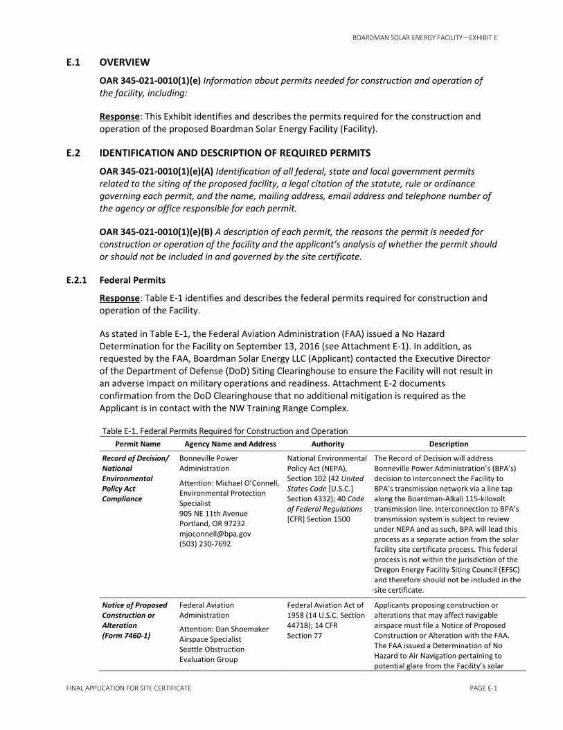
BOARDMAN SOLAR ENERGY FACILITY—EXHIBIT E
FINAL APPLICATION FOR SITE CERTIFICATE PAGE E-1
E.1 OVERVIEW
OAR 345-021-0010(1)(e) Information about permits needed for construction and operation of the facility, including:
Response: This Exhibit identifies and describes the permits required for the construction and operation of the proposed Boardman Solar Energy Facility (Facility).
E.2 IDENTIFICATION AND DESCRIPTION OF REQUIRED PERMITS
OAR 345-021-0010(1)(e)(A) Identification of all federal, state and local government permits related to the siting of the proposed facility, a legal citation of the statute, rule or ordinance governing each permit, and the name, mailing address, email address and telephone number of the agency or office responsible for each permit.
OAR 345-021-0010(1)(e)(B) A description of each permit, the reasons the permit is needed for construction or operation of the facility and the applicant’s analysis of whether the permit should or should not be included in and governed by the site certificate.
E.2.1 Federal Permits
Response: Table E-1 identifies and describes the federal permits required for construction and operation of the Facility.
As stated in Table E-1, the Federal Aviation Administration (FAA) issued a No Hazard Determination for the Facility on September 13, 2016 (see Attachment E-1). In addition, as requested by the FAA, Boardman Solar Energy LLC (Applicant) contacted the Executive Director of the Department of Defense (DoD) Siting Clearinghouse to ensure the Facility will not result in an adverse impact on military operations and readiness. Attachment E-2 documents confirmation from the DoD Clearinghouse that no additional mitigation is required as the Applicant is in contact with the NW Training Range Complex.
Table E-1. Federal Permits Required for Construction and Operation
Permit Name Agency Name and Address Authority Description
Record of Decision/ National Environmental Policy Act Compliance
Bonneville Power Administration
Attention: Michael O’Connell, Environmental Protection Specialist 905 NE 11th Avenue Portland, OR 97232 [email protected] (503) 230-7692
National Environmental Policy Act (NEPA), Section 102 (42 United States Code [U.S.C.] Section 4332); 40 Code of Federal Regulations [CFR] Section 1500
The Record of Decision will address Bonneville Power Administration’s (BPA’s) decision to interconnect the Facility to BPA’s transmission network via a line tap along the Boardman-Alkali 115-kilovolt transmission line. Interconnection to BPA’s transmission system is subject to review under NEPA and as such, BPA will lead this process as a separate action from the solar facility site certificate process. This federal process is not within the jurisdiction of the Oregon Energy Facility Siting Council (EFSC) and therefore should not be included in the site certificate.
Notice of Proposed Construction or Alteration (Form 7460-1)
Federal Aviation Administration
Attention: Dan Shoemaker Airspace Specialist Seattle Obstruction Evaluation Group
Federal Aviation Act of 1958 (14 U.S.C. Section 44718); 14 CFR Section 77
Applicants proposing construction or alterations that may affect navigable airspace must file a Notice of Proposed Construction or Alteration with the FAA. The FAA issued a Determination of No Hazard to Air Navigation pertaining to potential glare from the Facility’s solar

BOARDMAN SOLAR ENERGY FACILITY—EXHIBIT E
PAGE E-2 FINAL APPLICATION FOR SITE CERTIFICATE
Table E-1. Federal Permits Required for Construction and Operation
Permit Name Agency Name and Address Authority Description
[email protected] (425) 227-2791
arrays on September 13, 2016 (Attachment E-1). However, no permit is issued by the FAA. This federal process is not within the jurisdiction of EFSC and therefore should not be included in the site certificate.
Supplemental Notice of Actual Construction or Alteration (Form 7460-2)
Federal Aviation Administration
Attention: Dan Shoemaker Airspace Specialist Seattle Obstruction Evaluation Group [email protected](425) 227-2791
Federal Aviation Act of 1958 (14 U.S.C. Section 44718); 14 CFR Section 77
Submission of the Supplemental Notice of Actual Construction or Alteration form must be filed within 5 days after construction reaches its greatest height as specified in the No Hazard Determination. No permit is issued by the FAA. This federal process is not within the jurisdiction of EFSC and therefore should not be included in the site certificate.
E.2.2 State Permits: Not Federally Delegated
Response: Table E-2 identifies and describes the state permits not federally delegated and required for construction and operation of the Facility.
Table E-2. State Permits Not Federally Delegated
Permit Name Agency Name and Address Authority Description
Energy Facility Site Certificate
Oregon Department of Energy and Energy Facility Siting Council
Attention: Katie Clifford 550 Capitol Street N.E. Salem, OR 97301 [email protected] (503) 302-0267
Oregon Revised Statute (ORS) Chapter 469.300 et seq.; Oregon Administrative Rule (OAR) Chapter 345, Divisions 1, 15, 21- 24, 26-27
The Facility is an “energy facility” as defined in ORS Chapter 469.300(11) and must be authorized through a site certificate issued by the Energy Facility Siting Council. The Applicant has submitted a site certificate application pursuant to OAR 345-015-0300(3).
Onsite Sewage Disposal Construction-Installation Permit
Oregon Department of Environmental Quality
Water Quality Onsite Program, Eastern Region 800 SE Emigrant #330 Pendleton, OR 97801 Bob Marshall [email protected] (541) 276-4063
ORS Chapters 454 and 468B; OAR Chapter 340, Division 71
Facilities with an onsite sewage disposal system must obtain a Construction-Installation Permit before construction. The Facility will have a daily sewage flow of fewer than 2,500 gallons and the Applicant’s third-party contractor will obtain from the Oregon Department of Environmental Quality (DEQ) a Construction-Installation Permit for the operations and maintenance (O&M) facility. Therefore, this permit should not be included in and governed by the site certificate.
General Water Pollution Control Facilities Permit, WPCF-1700-B, Washwater Discharge from Equipment Cleaning
Oregon Department of Environmental Quality Eastern Region Eastern Region 700 SE Emigrant, Suite 330 Pendleton, OR 97801 (541) 276-4063
ORS 468B; OAR Chapter 340, Division 45
The solar modules may be washed twice annually and the washwater will be released to the ground and allowed to evaporate and infiltrate. The washwater will not be heated or include detergents. The WPCF-1700-B permit covers

BOARDMAN SOLAR ENERGY FACILITY—EXHIBIT E
FINAL APPLICATION FOR SITE CERTIFICATE PAGE E-3
Table E-2. State Permits Not Federally Delegated
Permit Name Agency Name and Address Authority Description
equipment-cleaning activities that discharge washwater by means of evaporation, seepage, or irrigation, including both fixed and mobile washing operations. The Applicant’s third-party contractor who will conduct the washing activities will seek coverage under the WPCF-1700-B permit from DEQ following completion of construction and before initiating any washing activities. Therefore, this permit should not be included in and governed by the site certificate.
Water Right Permit or Water Use Authorization
Oregon Water Resources Department
Scott Kudlemeyer 725 Summer St. NE, Suite A Salem, OR 97301 (541) 986-0861
ORS 537; OAR Chapter 690, Divisions 310, 340, 410 and 507
Facilities that withdraw groundwater must obtain a Water Right Permit or Water Use Authorization before construction. A well for the Facility O&M building will provide fewer than 5,000 gallons per day and therefore will be an exempted use while subject to the same privileges and restrictions as any permit or authorization. The Applicant’s third-party contractor will file the recorded well document directly with the Oregon Water Resources Department as it is outside the jurisdiction of EFSC and should not be included in and governed by the site certificate.
Oversize Load Movement Permit/Load Registration
Oregon Department of Transportation
Motor Carriers Transportation Division 550 Capitol Street NE Salem, OR 97301 Christy Jordan [email protected] (503) 378-6192
ORS Chapter 818.030; OAR Chapter 734, Divisions 51, 82
Access to the Facility will be provided by interstate and state highways. If large or overweight equipment needs to be moved across state roads, a permit and load registration will be required. Morrow County Public Works Department will provide local review. The Applicant’s third-party contractor will obtain this permit and load registration from the Oregon Department of Transportation before transporting large or overweight equipment and therefore this permit should not be included in and governed by the site certificate.
General Water Pollution Control Facilities Permit, WPCF-1000, Gravel Mining and Batch Plant
Oregon Department of Environmental Quality Eastern Region Eastern Region 700 SE Emigrant, Suite 330
ORS 468B; OAR Chapter 340, Division 45
A WPCF-1000 authorizes the permittee to operate a wastewater collection, treatment, control, and disposal system for sand, gravel, and other nonmetallic mineral quarrying and mining operations, including asphalt-mix batch plants,

BOARDMAN SOLAR ENERGY FACILITY—EXHIBIT E
PAGE E-4 FINAL APPLICATION FOR SITE CERTIFICATE
Table E-2. State Permits Not Federally Delegated
Permit Name Agency Name and Address Authority Description
Pendleton, OR 97801 (541) 276-4063
Department of Geology and Mineral Industries Mineral Land Regulation and Reclamation Program 229 Broadalbin St. SW Albany, OR 97321 (541) 967-2039
concrete batch plants, and other related activities. If a temporary batch plant is required for Facility construction, the Applicant’s third-party contractor will obtain a WPCF-1000 permit directly from DEQ and therefore this permit should not be included in and governed by the site certificate.
Archaeological Excavation Permit
Oregon Parks and Recreation Department, State Historic Preservation Office
725 Summer Street NE, Suite C Salem, OR 97301 Matt Diederich, MAIS [email protected] (503) 986-0577
ORS Chapters 97, 358, and 390; OAR Chapter 736, Division 51 (Permit and Conditions for Excavation or Removal of Archaeological or Historical Materials on Private Land)
During Facility construction, if a previously unidentified archaeological site is discovered, all construction will cease and the Applicant will report the finding to the State Historic Preservation Office (SHPO) immediately. In that instance, SHPO will require an archaeological excavation permit. The Applicant does not anticipate that this permit will be required (see Exhibit S for further discussion). However, should this permit be required, the Applicant will obtain it from SHPO and therefore this permit should not be included in and governed by the site certificate.
E.2.3 State Permits: Federally Delegated
Response: Table E-3 identifies and describes the state permits federally delegated and required for construction and operation of the Facility.
Table E-3. State Permits Federally Delegated
Permit Name Agency Name and Address Authority Description
National Pollution Discharge Elimination System (NPDES) Permit, 1200-C Construction Stormwater NPDES Permit
Oregon Department of Environmental Quality – Water Quality Division
Attention: Jackie Ray Eastern Region 800 SE Emigrant Avenue, Suite 330 Pendleton, OR 97801 [email protected] (541) 278-4605
Clean Water Act, Section 402 (33 U.S.C. Section 1342); 40 CFR Section 122; ORS Chapters 468 and 468B; OAR Chapter 340, Division 45
A 1200-C Permit regulates stormwater runoff from construction activities that disturb more than 1 acre of ground. Facility construction will disturb more than 1 acre and therefore a 1200-C Permit is required, as described further in Exhibit I. Attachment I-1 in Exhibit I contains the Applicant’s NPDES permit application. The Applicant will obtain this permit directly from DEQ as it is outside the jurisdiction of EFSC and should not be included in and governed by the site certificate.

BOARDMAN SOLAR ENERGY FACILITY—EXHIBIT E
FINAL APPLICATION FOR SITE CERTIFICATE PAGE E-5
Table E-3. State Permits Federally Delegated
Permit Name Agency Name and Address Authority Description
Basic Air Contaminant Discharge Permit (ACDP)
Oregon Department of Environmental Quality – Air Quality Division
Eastern Region 475 NE Bellevue, Suite 110Bend, OR 97701 (541) 633-2026
Clean Air Act (42 U.S.C. Section 7401 et seq.). 40 CFR Parts 50, 51, and 52 ORS Chapters 468 and 468A OAR Chapter 340, Division 216
A Basic ACDP authorizes the permittee to operate a stationary or portable concrete manufacturing plant that produces more than 5,000 but less than 25,000 cubic yards per year output. If a portable concrete manufacturing plant is required for Facility construction, a Basic ACDP will be obtained from DEQ. Attachment E-3 contains the Applicant’s ACDP application. The Applicant will obtain this permit directly from DEQ as it is outside the jurisdiction of EFSC and should not be included in and governed by the site certificate.
E.2.4 Local Permits
Response: Table E-4 identifies and describes the local permits required for construction and operation of the Facility. These permits, if applicable to the Facility, should be included in and governed by the site certificate.
Table E-4. Local Permits
Permit Name Agency Name and Address Authority Description
Conditional Use Permit (see Exhibit K)
Morrow County Planning Department
Attention: Carla McLane, Planning Director 205 NE Third Street Irrigon, OR 97844 [email protected] (541) 922-4624
Morrow County Zoning Ordinance (MCZO) Section 3.010, Exclusive Farm Use Zone; MCZO Article 6, Conditional Uses
This permit is required for commercial utility facilities that generate power for public use by sale and are proposed on land in the exclusive farm use (F-1) zone in accordance with MCZO Section 3.010.D.15. The Applicant demonstrates compliance with the conditional use standards contained in Article 6 of the MCZO, as well as other substantive criteria applicable to the proposed Facility, in Exhibit K. The Applicant elects to obtain an EFSC determination under ORS Chapter 469.504(1)(b).
Zoning Permit (see Exhibit K)
Morrow County Planning Department
Attention: Carla McLane, Planning Director 205 NE Third Street Irrigon, OR 97844 [email protected]
(541) 922-4624
Morrow County Zoning Ordinance (MCZO) Section 1.050, Zoning Permit; MCZO Article 1, Introductory Provisions
This permit is required prior to the construction, reconstruction, alteration, or change of use of any structure larger than 100 square feet. The Applicant demonstrates compliance with the conditional use standards contained in Article 1 of the MCZO, as well as other substantive criteria applicable to the proposed Facility, in Exhibit K. The Applicant elects to obtain an EFSC determination under ORS Chapter 469.504(1)(b).

BOARDMAN SOLAR ENERGY FACILITY—EXHIBIT E
PAGE E-6 FINAL APPLICATION FOR SITE CERTIFICATE
Table E-4. Local Permits
Permit Name Agency Name and Address Authority Description
Conditional Use Permit
Morrow County Planning Department
Attention: Carla McLane, Planning Director 205 NE Third Street Irrigon, OR 97844 [email protected]
(541) 922-4624
Morrow County Zoning Ordinance (MCZO) Section 3.010, Exclusive Farm Use Zone; Article 6, Conditional Uses
If a portable concrete manufacturing plant is required for Facility construction, a conditional use permit is required. TheApplicant’s third-party contractor will obtain this permit directly from Morrow County and therefore it should not be included in and governed by the site certificate.
Conditional Use Permit (see Exhibit K)
Gilliam County Planning Department
Attention: Michelle Colby, County Planner 221 S Oregon Street Condon, OR 9782 [email protected] (541) 384-2381
Gilliam County Zoning Ordinance (GCZO) Section 4.020, Exclusive Farm Use Zone; GCZO Article 7, Conditional Uses
This permit is required for utility facilities necessary for public service subject to the provisions of ORS 215.274 governing associated transmission lines necessary for public service. The Applicant demonstrates compliance with the criteria in ORS 215.274, the conditional use standards contained in Article 7 of the GCZO, and other substantive criteria applicable to the proposed Facility, in Exhibit K. The Applicant elects to obtain a Council determination under ORS Chapter 469.504(1)(b).
Building and Utility Permits
City of Boardman
Attention: Brett Cook 200 City Center Circle P.O. Box 229 Boardman, Oregon 97818 [email protected] (541) 571-0273
ORS Chapter 455 Building Code
This permit is applicable to aboveground Facility structures. Applications for requisite permits will be submitted to the City of Boardman, which handles Morrow County building permits outside of the city limits of Boardman and Irrigon, before construction.
E.3 PERMIT APPLICATIONS NOT FEDERALLY DELEGATED
OAR 345-021-0010(1)(e)(C) For any state or local government agency permits, licenses or certificates that are proposed to be included in and governed by the site certificate, evidence to support findings by the Council that construction and operation of the proposed facility will comply with the statutes, rules and standards applicable to the permit. The applicant may show this evidence:
(i) In Exhibit J for permits related to wetlands.
Response: No permits are required related to wetlands. Please see Exhibit J.
(ii) In Exhibit O for permits related to water rights.
Response: During Facility construction, water will be supplied by the City of Boardman. During Facility operation, water will either be supplied by the City of Boardman or a well located near the proposed O&M building. The well would produce fewer than 5,000 gallons per day for the O&M building. Oregon law allows exempt industrial and commercial uses up to 5,000 gallons per day from groundwater wells without a water right permit (ORS 537.545(1)(f)). Exempt industrial uses include water for drinking, flushing toilets, and using sinks, as well as other industrial uses during construction and operation of the Facility.
BOARDMAN SOLAR ENERGY FACILITY—EXHIBIT E
FINAL APPLICATION FOR SITE CERTIFICATE PAGE E-7
See Exhibit O for further discussion.
E.4 PERMIT APPLICATIONS FEDERALLY DELEGATED
OAR 345-021-0010(1)(e)(D) For federally-delegated permit applications, evidence that the responsible agency has received a permit application and the estimated date when the responsible agency will complete its review and issue a permit decision.
Response: The Applicant has separately prepared a NPDES 1200-C Permit application for the Facility (Attachment I-1 in Exhibit I). The Applicant anticipates a permit decision from DEQ before the start of Facility construction. Attachment I-2 in Exhibit I contains a response from DEQ verifying receipt of the Applicant’s application.
The Applicant has also separately prepared and received a Basic Air Contaminant Discharge Permit for the proposed temporary batch plant; the application and permit are provided here as Attachment E-3.
E.5 THIRD-PARTY STATE OR LOCAL PERMITS
OAR 345-021-0010(1)(e)(E) If the applicant relies on a state or local government permit or approval issued to a third party, identification of any such third-party permit and for each:
(i) Evidence that the applicant has, or has a reasonable likelihood of entering into, a contract or other agreement with the third party for access to the resource or service to be secured by that permit.
Response: Four state permits and one local permit, if required, will be obtained by the Applicant’s third-party contractors. The Applicant’s parent company, Invenergy, routinely relies on contractors to obtain a variety of third-party permits for constructing energy facilities such as those described in Exhibit D. Most recently, Invenergy contracted with Phoenix Solar, Inc., as general contractor for the 50-megawatt (MW) Luning Solar Energy Project in Nevada. Invenergy contracted with D.H. Blattner & Sons, Inc. (Blattner) to build the 72-MW Willow Creek Wind Project in Gilliam and Morrow counties and with Concord Construction, Inc. (Concord) to build the Willow Creek Wind Project O&M building. For this Facility, the Applicant will select one of these or other such qualified contractors that has experience constructing renewable energy facilities. As with past projects, Invenergy will only select a contractor (or contractors) who have a reasonable likelihood of securing the required permits.
An Onsite Sewage Disposal Construction-Installation Permit will be required before constructing any such system. An Onsite Sewage Disposal Construction-Installation Permit is a common permit required for the construction of renewable energy facilities in Oregon, as facilities often have bathrooms for operational employees. A contractor familiar with constructing renewable energy facilities is also familiar with obtaining this permit from the DEQ. For example, Concord, in collaboration with Westfall Septic Tank and Excavation in Hermiston, Oregon, received this permit for the Willow Creek Wind Project O&M building in 2008.
An Oversize Load Movement Permit/Load Registration will be required for transporting large or overweight equipment to the site over state roads. Like the permit described above, this permit is a common permit required for the construction of renewable energy facilities in Oregon given the nature of the facility components. A contractor familiar with constructing renewable energy facilities is also familiar with obtaining this permit from the DEQ. Blatter or its subcontractors

BOARDMAN SOLAR ENERGY FACILITY—EXHIBIT E
PAGE E-8 FINAL APPLICATION FOR SITE CERTIFICATE
routinely obtain these permits for delivery of oversize or overweight equipment over state roads.
If a temporary concrete batch plant is required, Invenergy will direct its contractor to obtain a conditional use permit from Morrow County and a General Water Pollution Control Facilities Permit (WPCF-1000) to manage wastewater and stormwater from the plant. These permits are common for the construction of renewable energy facilities, which require concrete footings, pads, and other infrastructure. A contractor familiar with constructing renewable energy facilities is also familiar with obtaining these permits from local jurisdictions and the DEQ. For example, Blattner worked in collaboration with W.I. Inc. in Arlington, Oregon, to receive temporary concrete batch plant permits for the Willow Creek Wind Project in 2008.
If solar module washing to improve production during operations is required, Invenergy will direct its contractor to obtain a General Water Pollution Control Facilities Washwater Discharge from Equipment Cleaning Permit (WPCF-1700-B). This permit covers equipment-cleaning activities that discharge washwater by means of evaporation, seepage, or irrigation, including both fixed and mobile washing operations. The Applicant’s third-party contractor who will conduct the washing activities will seek coverage under the permit from DEQ following completion of construction and before initiating any washing activities. To secure coverage under WPCF-1700-B, DEQ directs applicants to request coverage under the permit at least 30 days prior to the planned activity, although DEQ may accept applications filed less than 30 days from the planned activity on a case-by-case basis. Given the short permitting timeline and the fact that any module-washing activities would fit squarely within the terms of the general permit, if solar module washing is required, the Applicant’s third-party contractor has a high likelihood of obtaining permit coverage long before coverage may be needed.
(ii) Evidence that the third party has, or has a reasonable likelihood of obtaining, the necessary permit.
Response: As described above, the Applicant will select a contractor with proven credentials for acquiring applicable permits.
(iii) An assessment of the impact of the proposed facility on any permits that a third party has obtained and on which the applicant relies to comply with any applicable Council standard.
Response: A third-party contractor has not been selected. Accordingly, this provision is not applicable.
E.6 THIRD-PARTY FEDERALLY DELEGATED PERMITS
OAR 345-021-0010(1)(e)(F) If the applicant relies on a federally-delegated permit issued to a third party, identification of any such third-party permit and for each:
(i) Evidence that the applicant has, or has a reasonable likelihood of entering into, a contract or other agreement with the third party for access to the resource or service to be secured by that permit.
(ii) Evidence that the responsible agency has received a permit application.
(iii) The estimated date when the responsible agency will complete its review and issue a permit decision.

BOARDMAN SOLAR ENERGY FACILITY—EXHIBIT E
FINAL APPLICATION FOR SITE CERTIFICATE PAGE E-9
Response: The Applicant will not rely on a federally-delegated permit issued to a third party.
E.7 MONITORING
OAR 345-021-0010(1)(e)(G) The applicant's proposed monitoring program, if any, for compliance with permit conditions.
Response: The Applicant will comply with monitoring requirements from EFSC and any jurisdictions responsible for granting Facility permits or approvals. Specific monitoring measures are described in the applicable Exhibits of this Application as follows:
• Requirements for erosion control monitoring and reporting are described in Exhibits H and I.
• Requirements for monitoring during construction in or near streams or waters of the state/U.S. are described in Exhibit J.
• Requirements for cultural resource monitoring are described in Exhibit S.
• Requirements for wildlife monitoring are described in Exhibit P.
E.8 SUMMARY
On the basis of the information presented above, the Applicant has satisfied the requirements of OAR 345-021-0010(1)(e).

Attachment E-1 Federal Aviation Administration
Determination of No Hazard to Air Navigation

Mail Processing CenterFederal Aviation AdministrationSouthwest Regional OfficeObstruction Evaluation Group10101 Hillwood ParkwayFort Worth, TX 76177
Aeronautical Study No.2016-ANM-1504-OE
Page 1 of 3
Issued Date: 09/13/2016
Paul ThienpontBoardman-OROne South Waker DriveSuite 1800Chicago, IL 60606
** DETERMINATION OF NO HAZARD TO AIR NAVIGATION **
The Federal Aviation Administration has conducted an aeronautical study under the provisions of 49 U.S.C.,Section 44718 and if applicable Title 14 of the Code of Federal Regulations, part 77, concerning:
Structure: Solar Panel Boardman-OR_Tracking-ArrayLocation: Boardman, ORLatitude: 45-47-55.71N NAD 83Longitude: 119-59-23.61WHeights: 415 feet site elevation (SE)
10 feet above ground level (AGL)425 feet above mean sea level (AMSL)
This aeronautical study revealed that the structure does not exceed obstruction standards and would not be ahazard to air navigation provided the following condition(s), if any, is(are) met:
It is required that FAA Form 7460-2, Notice of Actual Construction or Alteration, be e-filed any time theproject is abandoned or:
_____ At least 10 days prior to start of construction (7460-2, Part 1)__X__ Within 5 days after the construction reaches its greatest height (7460-2, Part 2)
See attachment for additional condition(s) or information.Based on this evaluation, marking and lighting are not necessary for aviation safety. However, if marking/lighting are accomplished on a voluntary basis, we recommend it be installed and maintained in accordancewith FAA Advisory circular 70/7460-1 L.
This determination expires on 03/13/2018 unless:
(a) the construction is started (not necessarily completed) and FAA Form 7460-2, Notice of ActualConstruction or Alteration, is received by this office.
(b) extended, revised, or terminated by the issuing office.(c) the construction is subject to the licensing authority of the Federal Communications Commission
(FCC) and an application for a construction permit has been filed, as required by the FCC, within

Page 2 of 3
6 months of the date of this determination. In such case, the determination expires on the dateprescribed by the FCC for completion of construction, or the date the FCC denies the application.
NOTE: REQUEST FOR EXTENSION OF THE EFFECTIVE PERIOD OF THIS DETERMINATION MUSTBE E-FILED AT LEAST 15 DAYS PRIOR TO THE EXPIRATION DATE. AFTER RE-EVALUATIONOF CURRENT OPERATIONS IN THE AREA OF THE STRUCTURE TO DETERMINE THAT NOSIGNIFICANT AERONAUTICAL CHANGES HAVE OCCURRED, YOUR DETERMINATION MAY BEELIGIBLE FOR ONE EXTENSION OF THE EFFECTIVE PERIOD.
This determination is based, in part, on the foregoing description which includes specific coordinates , heights,frequency(ies) and power . Any changes in coordinates , heights, and frequencies or use of greater power willvoid this determination. Any future construction or alteration , including increase to heights, power, or theaddition of other transmitters, requires separate notice to the FAA.
This determination does include temporary construction equipment such as cranes, derricks, etc., which may beused during actual construction of the structure. However, this equipment shall not exceed the overall heights asindicated above. Equipment which has a height greater than the studied structure requires separate notice to theFAA.
This determination concerns the effect of this structure on the safe and efficient use of navigable airspaceby aircraft and does not relieve the sponsor of compliance responsibilities relating to any law, ordinance, orregulation of any Federal, State, or local government body.
Any failure or malfunction that lasts more than thirty (30) minutes and affects a top light or flashing obstructionlight, regardless of its position, should be reported immediately to (877) 487-6867 so a Notice to Airmen(NOTAM) can be issued. As soon as the normal operation is restored, notify the same number.
If we can be of further assistance, please contact our office at (202) 267-4525. On any future correspondenceconcerning this matter, please refer to Aeronautical Study Number 2016-ANM-1504-OE.
Signature Control No: 293302619-304528050 ( DNE )David MaddoxSpecialist
Attachment(s)Additional Information

Page 3 of 3
Additional information for ASN 2016-ANM-1504-OE
This application may present an adverse impact on military operations and readiness. The DoD requests that the developer contact the Executive Director, Department of Defense Siting Clearinghouse, by email, at [email protected] or by phone at 703-571-0076, to discuss potential mitigation options. The structure will be located within the confines or near a military training route or military training area. The proposed project is located in military training routes VR-1350 and VR-1351 and Navy requests notification when construction begins to allow the scheduling agency to submit a Special Operating Procedure note to the DoD Flight Information Publication AP/1B for glint/glare potential.

Attachment E-2 Department of Defense Siting
Clearinghouse Communication

1
Miner, Laura
From: Scanlon, Rhiannon G CTR (US) <[email protected]>
Sent: Thursday, September 15, 2016 7:56 AM
To: Miner, Laura
Subject: RE: [Non-DoD Source] FW: Solar project in Navy system
Signed By: SCANLON.RHIANNON.G.1502059854
Good morning Ms. Miner,
Thank you checking with the Clearinghouse. Occasionally not all comments are included in the DNH letters, but this
instance the concern from the Navy was relayed. As you are in contact with the NW Training Range Complex, there is no
need for an additional mitigation discussion. Thank you again for following up with the Clearinghouse. It is my hope that
your continued cooperation will help us preserve the operational, training, and testing capabilities of our nation's Armed
Forces.
V/r,
Rhiannon Scanlon
DoD Siting Clearinghouse
571-372-6876
-----Original Message-----
From: Miner, Laura [mailto:[email protected]]
Sent: Wednesday, September 14, 2016 2:07 PM
To: OSD Pentagon OUSD ATL Mailbox DoD Siting Clearing House <osd.pentagon.ousd-atl.mbx.dod-siting-clearing-
Cc: Meenaghan, Kevin G CIV USN NAVFAC NW SVD WA (US) <[email protected]>; Thienpont, Paul
Subject: [Non-DoD Source] FW: Solar project in Navy system
________________________________
Hello - we have recently received the attached FAA DNH for a solar project that requests we contact you to discuss
potential mitigation options. We have also been coordinating with the NW Training Range Complex on impact analysis
and there is a paragraph in the attached FAA DNH that includes his recommendation (see below and attached). Could
you please review and verify that no additional mitigation measures are required for this project?
Laura Miner | Senior Business Development Manager Invenergy LLC | Portland OR [email protected] | 503-964-
8900
This electronic message and all contents contain information which may be privileged, confidential or otherwise
protected from disclosure. The information is intended to be for the addressee(s) only. If you are not an addressee, any

2
disclosure, copy, distribution or use of the contents of this message is prohibited. If you have received this electronic
message in error, please notify the sender by reply e-mail and destroy the original message and all copies.
-----Original Message-----
From: Meenaghan, Kevin G CIV NAVFAC NW, AM [Caution-mailto:[email protected] < Caution-
mailto:[email protected] > ]
Sent: Thursday, June 02, 2016 11:10 AM
To: Miner, Laura <[email protected]>
Cc: Thienpont, Paul <[email protected]>
Subject: RE: Solar project in Navy system
Hi Laura,
The below comments were added to our portion of the OE/AAA system. The comments basically say that when the
project building begins, let FAA know. FAA will also add a note in Dept of Defense publications alerting aircrew to
possibly glare. This is back into FAA channels now, and you'll receive further word from them.
Best,
Kevin
----------------
2016-ANM-1504-OE is a fixed-angle Solar Farm Project proposed west of the town of Boardman, OR along the Columbia
River in the vicinity of the northwest low-level initial ingress point for NWSTF Boardman (R-5701). The developer
(Invenergy) has been sensitive to the military mission and has voluntarily submitted for Sandia Glint/Glare analysis and
the FAA OE/AAA determination process.
The Sandia analysis shows a moderate (yellow on the scale) potential for late-afternoon glare as aircraft pass over the
southwest portion of the solar array field between 1600-1700 PST at 500'AGL.
Because of the relatively narrow window of potential impact, the RCT recommends "No Object with provision." The
requested provision is for the FAA (and/or developer) to notify the Navy when project construction begins, so the
Scheduling Agency (NASWI) can submit a "Special Operating Procedure" note to the DoD Flight Information Publication
AP-1B; specifically, to notify pilots flying between points I-J of the VR-1350 & L-M of the VR-1351 to be aware of
potential glare from the solar development during the late afternoon ingress (1600-1700PST) to R-5701.
----------------
-----Original Message-----
From: Miner, Laura [Caution-mailto:[email protected] < Caution-mailto:[email protected] > ]
Sent: Tuesday, May 31, 2016 4:38 PM
To: Meenaghan, Kevin G CIV NAVFAC NW, AM
Cc: Thienpont, Paul
Subject: [Non-DoD Source] RE: Solar project in Navy system [UNSCANNED]
Great - thanks much.
This electronic message and all contents contain information which may be privileged, confidential or otherwise
protected from disclosure. The information is intended to be for the addressee(s) only. If you are not an addressee, any
disclosure, copy, distribution or use of the contents of this message is prohibited. If you have received this electronic
message in error, please notify the sender by reply e-mail and destroy the original message and all copies.
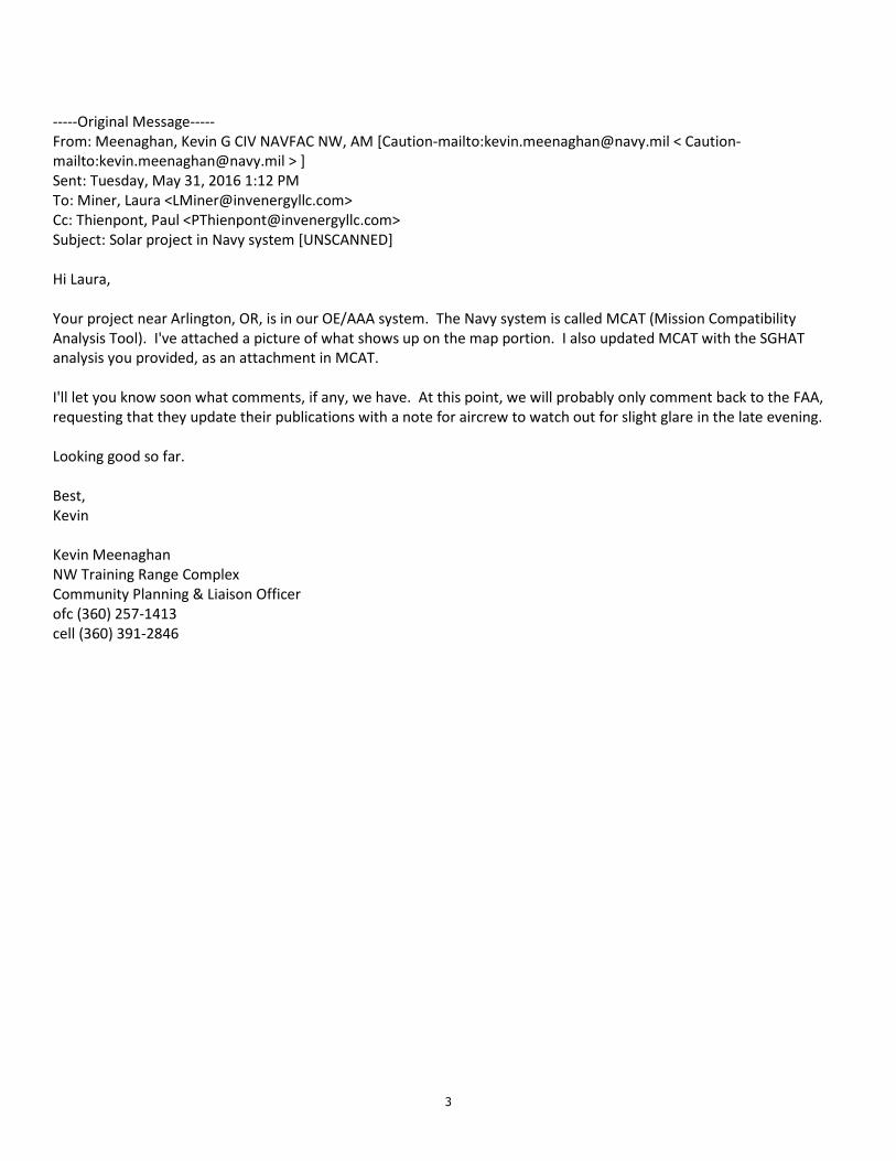
3
-----Original Message-----
From: Meenaghan, Kevin G CIV NAVFAC NW, AM [Caution-mailto:[email protected] < Caution-
mailto:[email protected] > ]
Sent: Tuesday, May 31, 2016 1:12 PM
To: Miner, Laura <[email protected]>
Cc: Thienpont, Paul <[email protected]>
Subject: Solar project in Navy system [UNSCANNED]
Hi Laura,
Your project near Arlington, OR, is in our OE/AAA system. The Navy system is called MCAT (Mission Compatibility
Analysis Tool). I've attached a picture of what shows up on the map portion. I also updated MCAT with the SGHAT
analysis you provided, as an attachment in MCAT.
I'll let you know soon what comments, if any, we have. At this point, we will probably only comment back to the FAA,
requesting that they update their publications with a note for aircrew to watch out for slight glare in the late evening.
Looking good so far.
Best,
Kevin
Kevin Meenaghan
NW Training Range Complex
Community Planning & Liaison Officer
ofc (360) 257-1413
cell (360) 391-2846

Attachment E-3 Basic Air Contaminant Discharge
Permit Application and Permit