bogie tube facts - alltubetesters.comalltubetesters.com/articles/bogey_tube_facts.pdf · bogie tube...
TRANSCRIPT
Bogie Tube Facts
What constitutes a Bogie Tube:The term Bogie generally references a target, or target value in the case of electronics.The electronic industry (of the day) definition of Bogie is:Each individual characteristic in the manufacturing specification is normally prescribed as a bogie valuewith plus and minus tolerances. The bogie value of a characteristic is the exact value specified for thatcharacteristic as set forth in the design standard of a specific tube type. It is the characteristic valvesestablished for the manufacturing specifications. The Modern Electronics Dictionary defines it as follows:1. Bogie - the average, nominal or published, value for a tube characteristic. A bogie tube would be onehaving all characteristics of a bogie (target) value. 2. An average, published, normal, or nominal value for some characteristic of a device.
Back in the day when tubes were the main active devises in electronic equipment, and were in massproduction, bogie tubes were actually manufactured with the intent of being a bogie, or standardtube. During the hay day of tube technology and manufacturing tube producers would make specialproduction runs of specific tube types to be used as Bogie tubes for specific needs within the industry. They paid close attention to the total assembly process, quality control in the production operation andtesting procedures. They allowed sufficient burn in times to insure a stable and accurate Gm value aswell as for many other characteristics. This was to insure these tubes were as close to the nominaldesign target values as could be achieved at the time. Today few if any tubes are made to this standardof attention to detail. When these tubes were manufactured they were built to meet the designspecifications the engineers established for that specific type of tube. These are the center designspecifications they tried to achieve, for the printed data sheets called nominal values.
Stepping back in time let us look at what a tube was designed for:Tubes were designed for specific operating conditions “Circuit applications”. There are manyapplications for vacuum tubes i.e., audio amplification, RF and IF amplification, Oscillator, Converteroperation, digital logic applications, signal rectification, power rectification, vertical and horizontalsweep applications. Thus each type of tube has a set of required operating characteristics necessary tooperate in the circuit of the equipment it was designed to work in. Electron tube design engineersdeveloped tubes with specifications specifically for the different circuits previously described. Thesecircuit operating characteristics are translated into electrical and mechanical design specificationsrequired to build the tube for the best operational performance in that application. It must be understoodthat all tubes of the same type number were not made equally and varied by manufacturer. . In themanufacturing process each tube type and in fact each tube would have design bogie values. The firstbogie values are based on the tube type, the second set are based on the manufacturing control and QC(Quality Control) process developed to try to keep the tube within the normal deviations (bell curve)standards required to meet the nominal design values. However, the true fact is that tube manufacturing ispart science & engineering and part artisan knowhow, heavily leaning toward experience and goodattention to every aspect of material processing control, human handling of the materials in productionand the interface of man/machine assembly process. Each tube manufacturer did many things differentlyincluding the physical build, tube structure, choice of materials used and quality of the materials inbuilding their tubes. Production process chosen and material handling methods. Thus the wide differencein tube quality, performance and life.
Typical tube application types were classified as follows:Voltage Amplifers, Power /Current Amplifers, Beam Power Tubes, Converters, Mixers, GatedAmplifers, FM Detectors, AM Detector Diodes, Power Supply Rectifiers, Relay-Control, Damper Tubes,TV Deflection, Regulators, UHF Oscillators, HF Oscillators, Mixer-Oscillators, High Voltage Rectifiers,complex wave generators, voltage regulators. Other classified characteristics were Lo Mu, Medium Mu,High Mu, Sharp-Cutoff, Semiremote-cutoff, Remote-cutoff, Low power transmitting tubes and highpower transmitting tubes and tubes for computers. Ya, the first early computers were operated by tubesand a lot of them. These tubes were not designed and intended to be sold for use as bogie tubes. Theyare simply tubes designed for specific applications
What then is a Bogie tube today?Today bogie tubes do not exist as in the past. Today tube makers focus primarily on producing enoughoutput in their regular and mostly audio tube production to meet sales demand! Which quite typicallyhas a wide range with regard to their Gm values from the nominal design target values. There is littleneed to go to the cost of producing a true Bogie tube of any tube type today with the exception of themanufacturing process itself. Additionally It is not likely anyone will come across a true bogie tube fromthe past as they were not built in high quantities back then. They were used only within the industry tocheck other equipment performance such as tube tester accuracy or for calibration purposes of tubetesters or other electronic test equipment. Or as a reference standard to compare to.Burned in tubes were sold for a similar reason used in various test equipment to insure proper calibrationranges for the equipment they were intended to be used in so the product could be used right away.
Today some suppliers will use a service tester like a Hickok 539C or some other such make or modelservice tester and test a tube and then market this as a Bogie tube for its Gm value only! They may alsosay it is for a particular make/model tester too. However, this is not a bogie tube. It is only a tube testedin a service tester and labeled as a bogie tube and it is only accurate to that persons tube tester accuracyand its tolerance value, or the ( +/-) accuracy of the service tester it was tested on. So in the case of a539C which if it were actually calibrated accurately, the factory specification for accuracy is +/- 10 % .In such a case the so called bogie tube could be any where within this range. So for example if the trueor accurate value of the bogie tube was 6000 Gm then the tester could show a measured value of + 10%or 6600 Gm or a low of 5,400 Gm and this would be considered within the acceptable range forcalibration. If the calibration was not performed properly or done to a higher degree of accuracy or thetester had internal issues un known to the user, as is often the reality today. In addition many testers likethe Hickok 600, 800, and 6000 series (other makes and models as well) have +/- 20% and/or 15%accuracy tolerance values. Some people will calibrate say a Hickok 600 model and then test a tube inthat tester and market it as a bogie tube and sell it as such stating the test value they obtained, but thiscould be way off from its actual Gm value. You then check your tester against this or actually calibrateyour tester to this tubes stated Gm value. You will be measuring your tester against the persons testerwho provide the tube. This is not a true professional Bogie tube or standard to check or calibrate yourtester to! Your tester may or may not actually be in proper or even close calibration as a result.
A bogie tube is tested and marketed for its actual Gm value based on laboratory controlled testing toinsure an accurate test result and should read this test value in any tube tester designed to measureGm values. The test results should be within the testers tolerance accuracy. But just as important itshould be extremely close to the actual bogie value stated for the highest accuracy.
So then a modern Bogie tube should be tested (as it is not likely to be produced as a true full Bogie tube),in accordance with good engineering practices and procedures to at least a tolerance value of +/- 1.5% of its true value. It would be nice to insure all tube specifications meet their nominal, publishedspecification values but this is just to costly to do in such a small tube market today and would requirehundreds of tubes be tested to meet this requirement, or a manufacturer to make a special production runof a tube type to achieve this requirement.
What then is the difference in the Bogie tubes I provide?Lets start with the fact that I only test these tubes in high end Laboratory testers all of which have designand rated accuracy values of +/- 1.5% or better. Each tester is checked for proper calibration at the startof each work day using a set of standards and high end test equipment calibrated to national standards. And these units are checked for proper calibration 4 times per year with a Fluke calibrator. Then thesetube testers are again checked prior to each batch (1 to 4 units) of potential bogie tubes before I start theprocess of testing a bogie tube to be sold. I follow best practices of laboratory testing proceduresthroughout the testing process.
I first do a initial test of purchased tubes and I reject tubes that are to far off to be used as a Bogie tube. The rest are then burned in as required to bring them as close to a Bogie value as can be achieved. I burnthese tubes in to a point of good stability and as close to their nominal published (design target) Gmvalues as can reasonably be achieved.
This process can take from 24 to 96 hours or more depending on the batch of tubes I received and pretested and accepted. As stated earlier my test equipment is calibrated and checked regularly to nationalstandards at great expense and thus all my test results are keep very tight.
The end result is a Bogie tube with a Gm value approaching as close to its nominal target value andaccurate to +/- 1.5% of its actual Gm value. No other tube specification is warrantied to for Bogievalues only Mutual Conductance (Gm). Why is this? Because I can not make from scratch (from rawmaterials) an all new production tube, controlling all materials, assembly process and quality controlprocess to build a truly all new Standard Bogie tube. As a result I am limited to purchase tubes already inthe market place. The vintage service testers that were designed to measure Gm also called MutualConductance or Transconductance were focused primarily on providing Gm test results and as I can onlypurchase normal production tubes I must focus on the Gm values and not try to cover all other tubespecification measurements. However, providing highly accurate and stable Reference or Gm Bogietubes is necessary if one wants to test or calibrate any Gm tube tester to a high degree or accuracy!
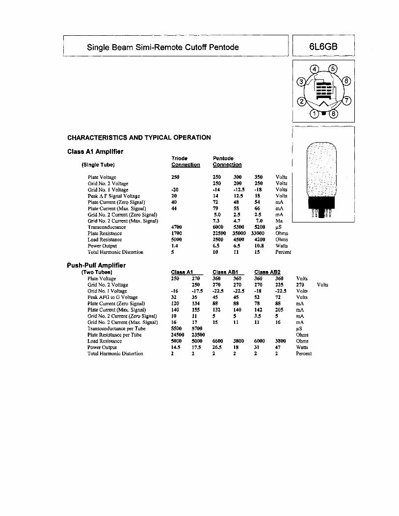
What are typical tube specifications?Typical information for any tube would contain such values and items as:- Maximum tube operating values,- Heater voltage & current,- Inter electrode capacitance,- Operating class characteristics,- Mutual conductance, also called Transconductance or the modern term of conductance is siemens, - Plate, & screen(s), voltages and currents. For more information see the last 2 pages of this PDF for the specifications of a 6L6 tube data sheet.
Back in those days all these specifications would have a maximum operating limits, and nominal (desiredtarget) value. The design targets had, by the basic nature of manufacturing a normal variation from thenominal target value. These variations were due to the type of materials used, quality of the materialsused in their construction, processing of the physical raw materials used in making the tubes componentparts in and during the manufacturing of the raw materials. In addition the physical processes of themachines and personnel in the making and handling of the parts up to and during the actual physicalinstallation of the parts in to the tube, and the sealing process of the tube. Everything man and machinedid to the tubes parts had, or caused some deviation from the ideal target specifications. Bogie tubeswere often made to meet the best overall nominal specification values. The most often process was tohand select the best of a normal batch of production tubes and test these to identify the those tubes withthe closest values to meet the desired bogie values that they were aiming to provide. The manufacturing control process had a large effect on meeting bogie values. Bogie tubes for thenormal sales market were usually aimed at Gm values primarily, with a secondary look at any excessivelevels of leakage and gas values, heater, filament current values, but beyond that little attention was paidto capacitance, smaller values of leakage or gas as a Bogie specification.
Today you will find tubes being sold as bogie, reference, or calibration tubes which have either not beentested under laboratory conditions with laboratory testers (properly calibrated and maintained regularly),but rather most often made on a typical service testers which they proclaim to be calibrated but can not ordo not provide tube Gm accuracy data , specification guarantees or warranties or actual tubespecifications.
How my bogie tubes are prepared:I purchase a batch of new 6L6 tubes. These may be Russian, or Chinese, or if available in quantity, NOSoriginal manufacturers types. I then test on a laboratory tester calibrated to within 1.5% or better. Eachtube is tested 2 times, twice on at least two different laboratory testers. However, before these testes areperformed these tubes are tested upon receipt looking for Good Gm range values, Heater to cathodeleakage, excessive leakage between other elements, gas, grid emissions, shorts, and any serious contactpotential, and those that have excessive levels of any of these are rejected. Then the acceptable tubes arepassed as usable. The next series of tests to the potential bogie tube is then begun. It is suppliedoperating voltages to its elements as stated in the tubes data sheet under typical operating conditionswhich are based on the design center values or bogie target nominal values.
In the first test the DC bias voltages is adjusted to obtain a DC plate current of 72.0 mA. All other valuesare as set forth as stated in the data sheet. These test results are log in for this tube. The second set oftests on this tube in the same laboratory tester is performed again, but in this test the DC bias is set to thedata sheet specified value of -14.0 DC bias volts. The plate current is allowed to go to whatever value itgoes to based on the values on its elements. At this point the two Gm values obtained from the two testsone at 72.0 mA of plate current and the other value obtained at a -14.0 DC bias voltage are thencompared. If the two Gm values are within no more than 600 Gm of each other I will accept the tubesand proceed to the next set of tests. The next two tests are repeated on the second laboratory tester toensure that both sets of tests are the same within 1.5% of each other at the worst case.
I now group the tubes that measured the closest to each other for the burn in process. The burn inprocess will vary by each batch based on the previous 2 tests on each tube and their actual results. Thefinal objective is to obtain tubes that are stable and have achieved acceptable test values which willprovide tight Gm and stable values, and with low drift values as all tubes will drift. The burn in processcan last from 12 hours to 94 hours or more depending on the tubes original test results.
Once this final process is completed the final two sets of tests are performed. Actually each set of testes involves over 200 individual tests performed in 1 volt increments. Once again the tests are performedjust as they were at the start, only in this case the final measurements are performed and documentedby computer automated data testing and storage. This ends up being the bogie tube stated testvalues. Once the second of the two tests groups are confirmed on a second laboratory tester the tube isnow done and all the data is prepared for the bogie tube document booklet. Each tube has its own testdata and the data booklet I assemble is only valid for that specific bogie tube.
My laboratory tube testers are tested each morning with a Golden Bogie tube. This tube is the best tube Ihave been able to obtain and burned in such that it is at its ideal nominal values, or no more than +/-0.5% of its nominal value. This test is performed daily at the start of my work day that and again before Istart the actual testing of bogie tubes. All the operating values of both laboratory testers are firstconfirmed and documented, then the golden bogie tube is tested and documented in each tester.
The entire process is quite labor intensive, and takes many hours to complete to insure a good bogie tube. When in the process I find a tube does not meet the requirements I have to start all over again withanother tube. Poor quality tubes do no one any good so quality and attention to detail is critical. A Bogietube should not be dropped, used as amplifier operation, left on for very long in a tester or for manyhours or operated at any heater voltage other than the nominal value designed for in the case of a 6L6 it is6.3 VAC or DC. Not lower or higher.
Today’s reality:Today a bogie tube will focus on its Gm as the main target. It is used to primarily check or calibrate atube tester. Tubes made on any service type tube tester can not be properly called true bogie tubes asthese service testers only have calibration accuracy values at best of +/- 10% with only a few make andmodel testers other wise it will be closer to +/-15 to 20% . And this is assuming the tester was servicedand calibrated correctly and tightly. By trying to calibrate a tester to the test value of a tube tested andrated on another service tester you can actually be reducing the accuracy of the tester you are tying tocalibrate. How is this possible? Well consider for a moment the following example of a quite typicalreal world true story that I see all to often.
A customer buys a Bogie tube made on a service tester (Hickok 539C) and he also owns a 539C tester. The tube is stated to be 5000 Gm and the test voltages and plate current and Gm value is supplied but no+/- Tolerance accuracy value is given and no accuracy warranty is provided. The customer calibrates histester using the same procedure that the supplier of the bogie tube used to calibrate his tester. However,after calibrating it, he becomes concerned as he notices all the tubes he tests seem to him to read low. Sohe sends his tester and bogie tube to me for service and calibration. The first thing I do is check his bogietube on his tester does reads it at 5000 Gm. The tube is rated at 5000 Gm according to the document sentwith it. Then I test his bogie tube on two laboratory testers and both measure it at 6200 Gm. So histester rates it at 5,000, Gm but the tube is really 6,200 Gm +/- 1.5% (6,107 to 6,293 Gm).
The tester was calibrated to the 5000 Gm stated on the tube which is what the seller stated was the actualGm of the tube based on the sellers calibrated 539C tester. So yes of course all the tubes he tested wouldhave been off by as much as 1200 Gm. Now consider a 12AX7 tube which is new and meeting itsnominal Gm value of 1600 Gm, but it would actually test as low as 400 Gm and 800 Gm is its rejectpoint.
For any tester to be used as a Standard in testing and rating the Gm of a tube to be used as aStandard Bogie tube the tester must actually be a Standard tester. This requires the proper and tight calibration be done and that all the operating values that make it a standard be monitored and verifiedthroughout the testing process and that a secondary confirmation test be performed to provide a checkand balance on the master tester. This is good laboratory procedure.
Summary:Bogie tubes today focus only on Gm values. A proper tube to be used (if accuracy is the focus) isprepared with laboratory equipment and under laboratory controlled conditions and best testing practices.A tube made on a service type tube tester is not a true bogie tube. This method of checking or calibratinganother tester based on the performance of someone’s similar tube tester will provide a wide range andlikely a high degree of error in the final result.
A word about Gm value, and testing or calibration of various tube testers using a bogie tube. It isimportant to note and understand that Gm (Mutual Conductance) is what it is regardless of the methodused to measure it. The measurement point on a tubes operational curve “slop” chosen can be at centerrating values (typical operational values) or at some other proportional testing values, as tubes will gavethe same Gm value at different points on the slope based on the proportional operating values applied toits elements. However, the Gm characteristic is the same at these same points when measured correctlyand will provide the same test result within the specific tube testers design accuracy tolerancespecification. The key is the proper operating potentials in the service tester including the normalized ones, adjustments and correct calibration. Typical service tube testers vary between +/- 10% to +/- 20%.
Where problems come in is a lack of full understanding of the actual technical facts of any tube testersdesign, operating method/principles, and its actual specifications. Often this is what leads many peopledown the wrong road. Unfortunately to many times information found on the net and from persons notfully trained/educated in the technology of the day, will passes on information that is misunderstood orincomplete and this leads to small errors witch grow and change as the information is repeated,interpreted, embellished, and passed on again. Sometimes its due to simple assumptions, or based onsome correct facts, (partial truths) but often not all the facts are provided, or some information is in error. I only provide actual technical facts and can support these with actual engineering explanations. I canpoint to the actual data, from engineering manuals, industry documents, text books, professionalscientific white papers and documents and other manuals. I deal in facts only, as sergeant Friday (TVshow Dragnet) would say “just the facts”. Oh - Yes I often try to simplify highly technicalmaterial/information so the non technical person can understand it, but I always site the technical facts aswell.
On the following pages you will see an example of a typical Bogie tube data manual. The actual datacharts and testing instructions are not provided so as to no be confusing to people who may not realizethe data is only a sample.
SAMPLE OF Bogie TUBE DATA MANUAL
STANDARD/REFERENCEBogie 6L6 TUBE
By Roger Kennedywww.alltubetesters.com
Tube Data & Charts
This booklet is only valid for the tube with the serialnumber that came with this documentation.
6L6 Serial No. Label:
Copyright 2012Roger Kennedy,Vintage Radio TV & Electronics,Services International.All rights reserved!
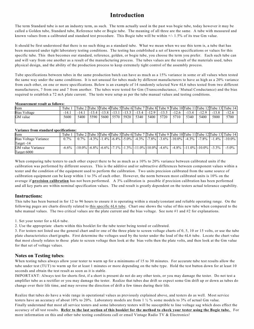
Introduction
The term Standard tube is not an industry term, as such. The term actually used in the past was bogie tube, today however it may be
called a Golden tube, Standard tube, Reference tube or Bogie tube. The meaning of all three are the same. A tube with measured and
known values from a calibrated and standard test procedure. This Bogie tube will be within +/- 1.5% of its true Gm value.
It should be first understood that there is no such thing as a standard tube. What we mean when we use this term is, a tube that has
been measured under tight laboratory testing conditions. The testing has established a set of known specifications or values for this
specific tube. This then becomes our standard, reference, golden, or bogie tube, you choose the term you prefer. Each such tube can
and will vary from one another as a result of the manufacturing process. The tubes values are the result of the materials used, tubes
physical design, and the ability of the production process to keep extremely tight control of the assembly process.
Tube specifications between tubes in the same production batch can have as much as a 15% variance in some or all values when tested
the same way under the same conditions. It is not unusual for tubes made by different manufacturers to have as high as a 20% variance
from each other, on one or more specifications. Below is an example of 14 randomly selected New 6L6 tubes tested from two different
manufacturers, 7 from one and 7 from another. The tubes were tested for Gm (Transconductance, / Mutual Conductance) and the bias
required to establish a 72 mA plate current. The tests were setup as per the tube manual values and testing conditions.
Measurement result as follows:Item Tube 1 Tube 2 Tube 3 Tube 4 Tube 5 Tube 6 Tube 7 Tube 8 Tube 9 Tube 10 Tube 11 Tube 12 Tube 13 Tube 14Bias Voltage -14.1 -14.1 -13.4 -13.8 -13.1 -13.3 -13.4 -12.9 -13.5 -12.6 -13.4 -12.9 -13.8 -12.6GM value 5600 5400 5590 5600 5570 5920 5340 5400 5720 5710 5340 5400 5800 5700
Variance from standard specifications:Item Tube 1 Tube 2 Tube 3 Tube 4 Tube 5 Tube 6 Tube 7 Tube 8 Tube 9 Tube 10 Tube 11 Tube 12 Tube 13 Tube 14Bias Voltage VarianceTarget -14
0.7% 0.7% -4.3% -1.4% -6.4% -5.0% -4.3% -7.8% -3.6% -10.0% -4.3% -7.8% -1.4% -10.0%
GM value VarianceTarget 6000
-6.6% -10.0% -6.8% -6.6% -7.1% -1.3% -11.0% -10.0% -4.6% -4.8% -11.0% -10.0% -3.3% -5.0%
When comparing tube testers to each other expect there to be as much as a 10% to 20% variance between calibrated units if the
calibration was performed by different sources. This is the additive and/or subtractive differences between component values within a
tester and the condition of the equipment used to perform the calibration. Two units precision calibrated from the same source of
calibration equipment can be keep within 1 to 3% of each other. However, the norm between most calibrated units is 10% on the
average if precision calibration has not been performed. A 3% calibration is possible if precision calibration has been performed
and all key parts are within nominal specification values. The end result is greatly dependent on the testers actual tolerance capability.
Instructions:This tube has been burned in for 12 to 96 hours to ensure it is operating within a steady/constant and reliable operating range. On the
following pages are charts directly related to this specific 6L6 tube. Chart one shows the value of this new tube when compared to the
tube manual values. The two critical values are the plate current and the bias voltage. See note #1 and #2 for explanations.
1. Set your tester for a 6L6 tube.
2. Use the appropriate charts within this booklet for the tube tester being tested or calibrated.
3. For testers not listed use the general chart and/or one of the three plate to screen voltage charts of 0, 5, 10 or 15 volts, or use the tube
plate characteristics chart/graphs. First determine the voltages used by the tester under the load of the 6L6 tube. Locate the chart value
that most closely relates to those plate to screen voltage then look at the bias volts then the plate volts, and then look at the Gm value
for that set of voltage values.
Notes on Testing tubes:
When testing tubes always allow your tester to warm up for a minimums of 15 to 30 minutes. For accurate tube test results allow the
tube under test (TUT) to warm up for at least 1 minutes or more depending on the tube type. Hold the test button down for at least 10
seconds and obtain the test result as soon as it is stable.
IMPORTANT: Always test for shorts first, if a short is present do not do any other tests, or you may damage the tester. Do not test a
amplifier tube as a rectifier or you may damage the tester. Realize that tubes due drift so expect some Gm drift up or down as tubes do
change over their life time, and may reverse the direction of drift a few times during their life.
Realize that tubes do have a wide range in operational values as previously explained above, and testers do as well. Most service
testers have an accuracy of about 10% to 20%. Laboratory models are from 1 ½ % some models to 3% of actual Gm value.
Finally understand that most all service testers and some laboratory testers will be susceptible to line voltage sag which does effect the
accuracy of all test results. Refer to the last section of this booklet for the method to check your tester using the Bogie tube. For
more information on this and other tube testing conditions call or email Vintage Radio TV & Electronics!
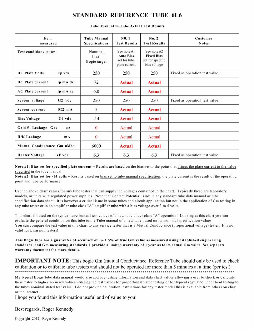
STANDARD REFERENCE TUBE 6L6
Tube Manual vs Tube Actual Test Results
Item
measured
Tube Manual
Specifications
N0. 1
Test Results
No. 2
Test Results
Customer
Notes
Test conditions notes Nominal
Ideal
Bogie target
See note #1Auto Biasset for tube
plate current
See note #2Fixed Bias
set for specificbias voltage
DC Plate Volts Ep vdc 250 250 250 Fixed as operation test value
DC Plate current Ip mA dc 72 Actual Actual
AC Plate current Ip mA ac 6.0 Actual Actual
Screen voltage G2 vdc 250 250 250 Fixed as operation test value
Screen current IG2 mA 5 Actual Actual
Bias Voltage G1 vdc -14 Actual Actual
Grid #1 Leakage Gas uA 0 Actual Actual
H/K Leakage mA 0 Actual Actual
Mutual Conductance Gm uMho 6000 Actual Actual
Heater Voltage eF vdc 6.3 6.3 6.3 Fixed as operation test value
Note #1: Bias set for specified plate current = Results are based on the bias set to the point that brings the plate current to the value
specified in the tube manual.
Note #2: Bias set for -14 volts = Results based on bias set to tube manual specification, the plate current is the result of the operating
point and tube performance.
Use the above chart values for any tube tester that can supply the voltages contained in the chart. Typically these are laboratory
models, or units with regulated power supplies. Note that Contact Potential is not in any standard tube data manual or tube
specification data sheet. It is however a critical issue in some tubes and circuit application but not in the application of Gm testing in
any tube tester or in an amplifier tube class “A” amplifier tube with a bias voltage over 3 to 5 volts.
This chart is based on the typical tube manual test values of a new tube under class “A” operation! Looking at this chart you can
evaluate the general condition on this tube to the Tube manual of a new tube based on its nominal specification values.
You can compare the test value in this chart to any service tester that is a Mutual Conductance (proportional voltage) tester. It is not
valid for Emission testers!
This Bogie tube has a guarantee of accuracy of +/- 1.5% of true Gm value as measured using established engineering
standards, and Gm measuring standards. I provide a limited warranty of 1 year as to its actual Gm value. See separate
warranty document for more details.
IMPORTANT NOTE: This bogie Gm (mutual Conductance Reference Tube should only be used to checkcalibration or to calibrate tube testers and should not be operated for more than 5 minutes at a time (per test).**************************************************************************************************************
My typical Bogie tube data manual would also include testing information and data chart values allowing a user to check or calibrate
their tester to higher accuracy values utilizing the test values for proportional value testing or for typical regulated under load testing to
the tubes nominal stated test value. I do not provide calibration instructions for any tester model this is available from others on ebay
or the internet!
I hope you found this information useful and of value to you!
Best regards, Roger Kennedy
Copyright 2012, Roger Kennedy