boilerplate fiber horizontal design - 27 15 23 · web viewpanels shall protect network equipment by...
TRANSCRIPT

CSI SECTION 271523
COMMUNICATIONS OPTICAL FIBER
HORIZONTAL CABLING
The purpose of this document is to provide documentation to cabling professionals interested in providing their customer a standard specification applicable to commercial building structured cabling applications.
The documentation includes: Product specifications, minimum product performance, structured cabling design considerations and installation guidelines.
The information contained in this document is based on our experience to date and is believed to be reliable. It is intended as a guide for use by persons having technical skill and is to be used with their own discretion and risk. We do not guarantee favorable results or assume any liability in connection with its use. Dimensions contained herein are for reference purposes only. For specific dimensional requirements consult the factory. This publication is not to be taken as a license to operate under, or a recommendation to infringe any existing patents. This supercedes and voids all previous literature, etc.
It is highly recommended and the issuers responsibility to have any RFQ documents, including those based on this general format, reviewed by the issuing company’s professional advisors before it is released to the public. In no way may this document be used in a manner that is detrimental to the interests of Panduit and/or its subsidiaries.
27 15 23 Communications Optical Fiber Horizontal Cabling] Page 1

TABLE OF CONTENTS
PART 1 - GENERAL...............................................................................................3
1.1 Work Included....................................................................................................................................3
1.2 Scope of Work.....................................................................................................................................3
1.3 Regulatory References.......................................................................................................................4
1.4 Quality Assurance..............................................................................................................................4
1.5 Approved Products.............................................................................................................................5
PART 2 - PRODUCTS.............................................................................................5
2.1 Equivalent Products...........................................................................................................................5
2.2 Substitutions – (no exceptions)..........................................................................................................5
2.3 Work Area Subsystem.......................................................................................................................6
2.4 Horizontal Distribution Cabling.............................................................................................................8
2.5 Telecommunication Room......................................................................................................................8
PART 3 - EXECUTION..........................................................................................10
3.1 Work Area Outlets...........................................................................................................................10
3.2 Horizontal Distribution Cable Installation....................................................................................10
3.3 Vertical Outlet Pole and Surface Raceway – See Appendix “E”.................................................11
3.4 Racks..................................................................................................................................................12
3.5 Firestop System.................................................................................................................................12
3.6 Grounding System - Please see Appendix “F”..........................................................................12
3.7 Identification and Labeling – Please See Appendix “D”..........................................................12
3.8 Testing and Acceptance - See Appendix “C”...........................................................................125
3.9 System Documentation...............................................................................................................126
Section 27152327 15 23 Communications Optical Fiber Horizontal Cabling] Page 2

COMMUNICATIONS OPTICAL FIBER HORIZONTAL CABLING REQUIREMENTS
Part 1 - General1.1Work Included
A. Provide all labor, materials, tools and equipment required for the complete installation of work called for in the Construction Documents
1.2Scope of WorkA. This document describes the products and execution requirements relating to
furnishing and installing Telecommunications Cabling for the horizontal cabling comprised of Optical Fiber Cabling, and support systems are covered under this document.
Install a structured cabling system that will be able to support interconnections to active telecommunications equipment for voice and data applications in a multi vendor, multi product environment. The structured cabling system should adhere to ANSI/TIA 568-B; 569-A; 606-A;J-STD-607-A and TIA 942 standards with respect to pathways, distribution, administration, and grounding of the system. The structured cabling system to be installed should also follow the guidelines spelled out in this RFP in accordance to local codes and regulations.
For Reference of the drops, each Standard drop will consist of three terminations that can be interoperable to accommodate either voice or data applications. Each meeting room drop will consist of four drops each consisting of two terminations can be interoperable to accommodate either voice or data applications. There will also be convenience phone drops that will consist of a single termination that will be installed in the proper faceplate for each location’s phone.
Install, terminate, test, and guarantee each drop according to customer all applicable standards and customer preferences.
Horizontal cables will be rated 50µm Laser Optimized Fiber (LOF) enhanced in performance rated to connector outlets at the work area. The Horizontal cables will home run back to a floor serving telecommunications room and will terminate with individual SC or LC optical fiber connectors to a modular 48 fiber enclosure. All cables will be patched at cutover as an interconnection into the floor serving active equipment using 50µm LOF equipment cables with SC or LC optical fiber connectors.
The floor serving active data equipment will be interconnected to the facility serving data equipment via a fiber backbone terminated in 19” rack mounted 48 port enclosures which will utilize SC or LC connections. This will serve to connect the Main Telecommunications Room to an additional Telecommunications Room serving the locations that exceed the distance limitations (90 meters) of the Main Telecommunications Room for the horizontal Data and Voice drops.
Contractor will also be required to make matching additions to the cable tray to complete the system according to ANSI/TIA 569
B. This section includes minimum requirements for the following:• Optical Fiber from TR to Work Area• Fiber WA Patch Cords• Optical Fiber Connector Modules
C. All cables and related terminations, support and grounding hardware shall be furnished, installed, wired, tested, labeled, and documented by the Telecommunications contractor as detailed in this document.
D. Product specifications, general design considerations, and installation guidelines are provided in this document. Quantities of telecommunications outlets, typical installation details, cable routing and outlet types will be provided as an attachment to this document. If the bid documents are in conflict, formal clarification shall be obtained from in the form of Question Clarification Request. The successful vendor
27 15 23 Communications Optical Fiber Horizontal Cabling] Page 3

shall meet or exceed all requirements for the cable system described in this document.
1.3Regulatory References
A. The following industry standards are the basis for the structured cabling system described in this document.1. ANSI/TIA
TIA-568-B Commercial Building Telecommunications Cabling Standard
TIA-568-B.1 General Requirements TIA-568-B.2 Balanced Twisted Pair Cabling Components Standard TIA-568-B.2.10 Specifications for Augmented Category 6 Cabling TIA-568-C.3 Optical Fiber Cabling Components Standard TIA-942 Telecommunications Infrastructure for Data Centers TIA-569-A Commercial Building Standard for Telecom Pathways
and Spaces TIA-606-A Administration Standard for the Telecommunications
Infrastructure of Commercial Buildings J-STD-607-A Commercial Building Grounding/Bonding
Requirements2. NFPA
NFPA 70 National Electric Code (NEC) 3. ISO/IEC
ISO 11801 Generic Cabling for Customer Premises
B. If there is a conflict between applicable documents, then the more stringent requirement shall apply. All documents listed are believed to be the most current releases of the documents. The Contractor has the responsibility to determine and adhere to the most recent release when developing the proposal for installation.
C. This document does not replace any code, either partially or wholly. The contractor must be aware of local codes that may impact this project.
1.4Quality Assurance
A. Cabling System Warranty
1. A Cable Products Warranty shall provide a complete warranty to guarantee a high performance cabling systems that meet application requirements. The guarantee shall include all cable installed in the structured cabling system. The Cable shall be warranted for a period of at least 25 years.
B. PANDUIT System Warranty
1. A CERTIFICATION PLUS System Warranty shall provide a complete system warranty to guarantee end-to-end high performance cabling systems that meet application requirements. The guarantee shall include copper connectivity components. The system shall be warranted for a period of at least 25 years.
C. Product Guarantee
All PANDUIT PAN-NET ™ non-consumable products have a 25-year guarantee. When installed per TIA or ISO/IEC standards, the PANDUIT PAN-NET Network Cabling System will operate the application(s) for which the system was designed to support.
In order to qualify for the guarantee, the structured cabling system must be installed per the following:1. Meet all TIA commercial building wiring standards2. Panduit will provide a single source solution for the end-to-end installation
27 15 23 Communications Optical Fiber Horizontal Cabling] Page 4

3. Panduit Products must be installed per Panduit instruction sheets by a BICSI certified Installer with minimum agreement of Panduit Certified Installer by Panduit Corp.
Installer: Company specializing in installing products specified in this section with minimum three years documented experience, and with service facilities within 120 miles of project. The Electrical/Telecommunications contractor must be Panduit Corp. approved for cabling and fiber solutions – a qualified BICSI trained installer who also is certified to install Warrantee-able solution by Panduit Corp.. A copy of certification documents for each must be submitted with the quote in order for such quote to be valid.
The Electrical/Telecommunications contractor is responsible for workmanship and installation practices in accordance with the Panduit cabling solutions Certified Program. Manufacturer (Panduit) will extend a 25-year Static, Dynamic and Applications Warranty to the end user once the Electrical/Telecommunications contractor fulfills all requirements under the Panduit Cabling Solutions Certified Program. At least 30 percent of the installation and termination crew must be certified by Panduit with a Technicians Level of Training. Also, Panduit must certify 10 percent of the installation and termination crew for Optical Fiber Training.
Note: All Networks shall be installed per applicable standards and manufacturer's guidelines.
If any PANDUIT PAN-NETTM product fails to perform as stated above, PANDUIT will provide new components at no charge.
THIS GUARANTEE IS MADE IN LIEU OF AND EXCLUDES ALL OTHER WARRANTIS, EXPRESSED OR IMPLIED. THE IMPLIED WARRANTIES OF MERCHANTABILITY AND FITNESS FOR A PARTICULAR USE ARE SPECIFICALLY EXCLUDED. Neither seller nor manufacturer shall be liable for any other injury, loss or damage, whether direct or consequential.
1.5 Approved Products
A. Approved Optical Fiber Cable manufacturer: PanduitB. Approved Fiber Optic cabinet product manufacturer: Panduit C. Approved Fiber Optic connectors/splices/couplers: Panduit D. Approved Rack and Cabinet manufacturer: Panduit E. Approved Fiber Optic Patch Cord manufacturer: Panduit
Part 2 - Products
2.1Equivalent Products
A. Panduit shall manufacture all products, including but not limited to cable management, faceplates, copper modules, patch panels, racks, 110 blocks, patch cords, labels, grounding lugs and fiber connectivity products for the purpose of this document.
B. Panduit Corp. shall manufacture all data/telecommunication and fiber optic cable.
2.2Substitutions – (no exceptions)
A. This is a performance-based single source solution. Therefore, substitutions are highly discouraged. Substitutions must follow the same rigid standards for quality and termination style as those described in section 2.3 and 2.5.
B. Any Contractor wishing to offer structured cabling products other than those specified herein shall submit a request for product substitution in writing no less than one week in advance of bid. Written requests for substitution shall be accompanied by all drawings, specification sheets and engineering documents, as well as third party laboratory performance test results proving equivalency in performance and manufacturing style.
27 15 23 Communications Optical Fiber Horizontal Cabling] Page 5

C. This written documentation shall be accompanied by samples of the substitution product offered for evaluation. Equal product acceptance must be received in writing.
D. Contractor shall be responsible and assume all costs for removal and replacement of any substituted product installed without prior written approval. Such costs shall include, but not be limited to labor, materials as well as any penalties, fees or costs incurred for late completion.
2.3 Work Area Subsystem
A. The Work Area shall consist of the connectivity equipment used to connect the horizontal cabling subsystem and the equipment in the work area. Both copper and fiber media shall be supported. The connectivity equipment shall include the following options:
• Patch (equipment) cords and modular connectors• Outlets and surface mount boxes• Surface raceway and outlet poles• Consolidation point / MUTO
B. Patch Cords and Modular Connectors
1. The modular connectors and patch cords will be chosen to match the horizontal cabling medium and rating. The same manufacturer shall provide the modular connectors and patch cords. The total patch cord length at the work area is not to exceed 3 meters (10 ft). Exception: When implementing an open office cabling system as specified under TIA TSB-75 (see section 3.4).
C. Fiber Optics
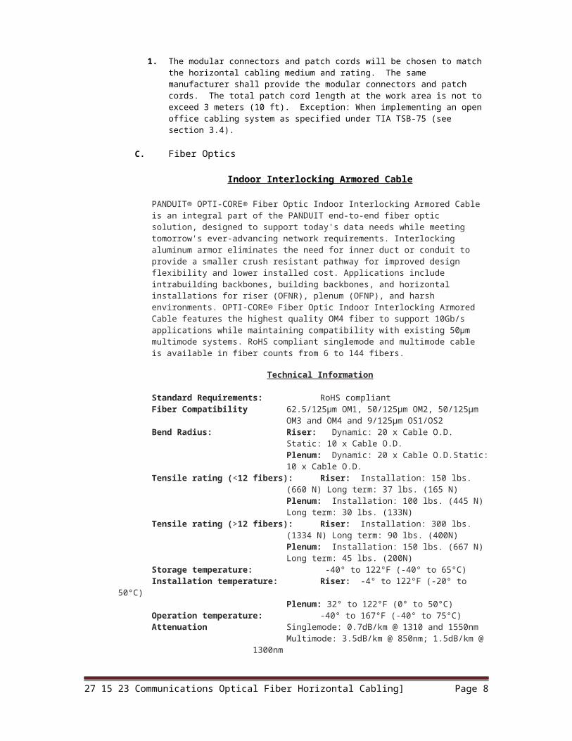
Indoor Interlocking Armored Cable
PANDUIT® OPTI-CORE® Fiber Optic Indoor Interlocking Armored Cable is an integral part of the PANDUIT end-to-end fiber optic solution, designed to support today's data needs while meeting tomorrow's ever-advancing network requirements. Interlocking aluminum armor eliminates the need for inner duct or conduit to provide a smaller crush resistant pathway for improved design flexibility and lower installed cost. Applications include intrabuilding backbones, building backbones, and horizontal installations for riser (OFNR), plenum (OFNP), and harsh environments. OPTI-CORE® Fiber Optic Indoor Interlocking Armored Cable features the highest quality OM4 fiber to support 10Gb/s applications while maintaining compatibility with existing 50μm multimode systems. RoHS compliant singlemode and multimode cable is available in fiber counts from 6 to 144 fibers.
Technical Information
Standard Requirements: RoHS compliantFiber Compatibility 62.5/125μm OM1, 50/125μm OM2, 50/125μm OM3
and OM4 and 9/125μm OS1/OS2Bend Radius: Riser: Dynamic: 20 x Cable O.D. Static: 10 x Cable
O.D.Plenum: Dynamic: 20 x Cable O.D.Static: 10 x Cable O.D.
Tensile rating (<12 fibers): Riser: Installation: 150 lbs. (660 N) Long term: 37 lbs. (165 N)Plenum: Installation: 100 lbs. (445 N) Long term: 30 lbs. (133N)
Tensile rating (>12 fibers): Riser: Installation: 300 lbs. (1334 N) Long term: 90 lbs. (400N)Plenum: Installation: 150 lbs. (667 N) Long term: 45 lbs. (200N)
Storage temperature: -40° to 122°F (-40° to 65°C)Installation temperature: Riser: -4° to 122°F (-20° to 50°C)
Plenum: 32° to 122°F (0° to 50°C)
27 15 23 Communications Optical Fiber Horizontal Cabling] Page 6

Operation temperature: -40° to 167°F (-40° to 75°C)Attenuation Singlemode: 0.7dB/km @ 1310 and 1550nm
Multimode: 3.5dB/km @ 850nm; 1.5dB/km @ 1300nm
Aluminum interlocking armor: Provides superior crush resistance and eliminates the need for inner duct or conduit with a smaller pathway for improved design flexibility and lower installed cost
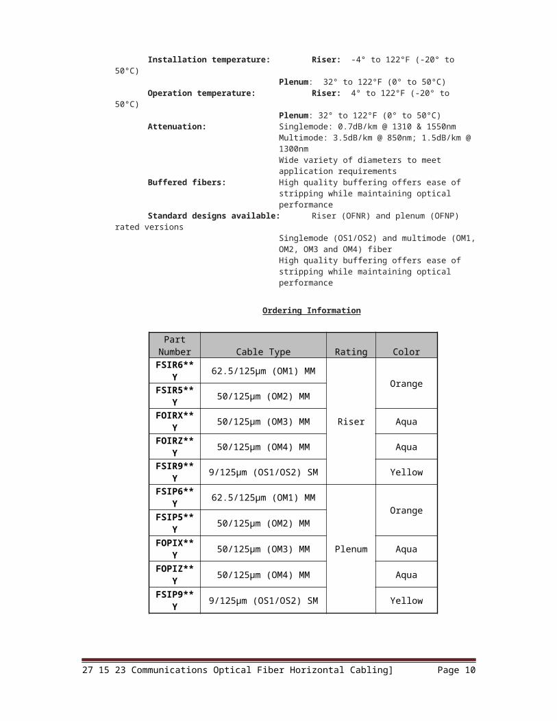
Ordering Information
Interconnect Cable
PANDUIT® OPTI-CORE® Fiber Optic Interconnect Cable is an integral part of the PANDUIT end-to-end fiber optic solution, designed to support today’s data needs while meeting tomorrow’s ever-advancing network requirements. OPTI-CORE® Fiber Optic Interconnect Cable is used within buildings to extend or interconnect network segments. The small cable size allows for installation in pace-restricted areas for applications that include horizontal cabling systems in support of high end workstations, secure networks and zone cabling. Interconnect cable can also be used for patch cords and jumpers. OPTI-CORE® Fiber Optic Interconnect Cable features the highest quality OM4 fiber to support 10Gb/s applications while maintaining compatibility with existing 50μm multimode systems. Standard RoHS compliant and duplex singlemode and multimode interconnect cable is available in riser and plenum rated constructions.
Technical Information
Standard Requirements: RoHS compliantFiber Compatibility: 62.5/125μm OM1, 50/125μm OM2, 50/125μm OM3
and OM4 and 9/125μm OS1/OS2Bend radius: Riser: Dynamic: 20 x Cable O.D. Static: 10 x Cable
O.D.Plenum: Dynamic: 20 x Cable O.D. Static: 10 x Cable O.D.
Tensile rating: Riser: Installation: 50 lb. (220 N) Long Term: 12.5 lb. (55 N)Plenum: Installation: 50 lb. (220 N) Long Term: 12.5 lb. (55 N)
Storage temperature: -40° to 150°F (-40° to 65°C)Installation temperature: Riser: -4° to 122°F (-20° to 50°C)
Plenum: 32° to 122°F (0° to 50°C)Operation temperature: Riser: 4° to 122°F (-20° to 50°C)
Plenum: 32° to 122°F (0° to 50°C)Attenuation: Singlemode: 0.7dB/km @ 1310 & 1550nm
Multimode: 3.5dB/km @ 850nm; 1.5dB/km @ 1300nmWide variety of diameters to meet application requirements
Buffered fibers: High quality buffering offers ease of stripping while maintaining optical performance
Standard designs available: Riser (OFNR) and plenum (OFNP) rated versions
27 15 23 Communications Optical Fiber Horizontal Cabling] Page 7
Part Number Cable Type Rating Color
FSPR6**Y 62.5/125µm (OM1) MM
Riser
OrangeFSPR5**Y 50/125µm (OM2) MMFOPRX**Y 50/125µm (OM3) MM AquaFOPRZ**Y 50/125µm (OM4) MM AquaFSPR9**Y 9/125µm (OS1/OS2) SM YellowFSPP6**Y 62.5/125µm (OM1) MM
Plenum
OrangeFSPP5**Y 50/125µm (OM2) MMFOPPX**Y 50/125µm (OM3) MM AquaFOPRZ**Y 50/125µm (OM4) MM AquaFSPP9**Y 9/125µm (OS1/OS2) SM Yellow
Singlemode (OS1/OS2) and multimode (OM1, OM2, OM3 and OM4) fiberHigh quality buffering offers ease of stripping while maintaining optical performance
Ordering Information
Distribution Cable
PANDUIT® OPTI-CORE® Fiber Optic Distribution Cable is an integral part of the PANDUIT end-to-end fiber optic solution, designed to support today's data needs while meeting tomorrow’s ever-advancing network requirements. OPTI-CORE® Fiber Optic Distribution Cable is used within buildings to provide high-density connectivity and ease of installation. Applications include intrabuilding backbones, routing between telecommunications rooms and connectorized cables in riser and plenum environments. OPTI-CORE® Fiber Optic Distribution Cable features the highest quality OM3 and OM4 to support 10Gb/s applications while maintaining compatibility with existing 50μm multimode systems. Standard RoHS compliant singlemode and multimode distribution cable is available in fiber counts from 6 to 72 fibers. Distribution cable in 6 and 12 fiber stranded designs have 900μm tight-buffered fibers surrounded by an aramid yarn strength member. Larger distribution cable (greater than 24 fibers) features a sub-unit design that simplifies fiber identification, provides easy access and routing of the fibers and increases cable durability with a dielectric central strength member.
Technical Information
Standards Requirements: Telcordia GR-20, Issue 2, GR-409 and with relevant TIA-455 series FOTPs for fiber optic cables
Fiber Compatibility: 62.5/125μm OM1, 50/125μm OM2, 50/125μm OM3 and OM4 and 9/125μm OS1/OS2
Bend radius: Riser: Dynamic: 20 x Cable O.D. Static: 10 x Cable O.D.Plenum: Dynamic: 20 x Cable O.D. Static: 10 x Cable O.D.
Tensile rating (<12 fibers): Riser: Installation: 150 lb. (660 N) Long Term: 37 lb. (165 N)Plenum: Installation: 100 lb. (440 N)Long Term: 24 lb. (110 N)
Tensile rating (>12 fibers): Riser: Installation: 300 lb. (1300 N) Long Term: 74 lb. (330 N)Plenum: Installation: 150 lb. (660 N) Long Term: 37 lb. (165 N)
27 15 23 Communications Optical Fiber Horizontal Cabling] Page 8
Part Number Cable Type Rating Color
FSIR6**Y 62.5/125µm (OM1) MM
Riser
OrangeFSIR5**Y 50/125µm (OM2) MMFOIRX**Y 50/125µm (OM3) MM AquaFOIRZ**Y 50/125µm (OM4) MM AquaFSIR9**Y 9/125µm (OS1/OS2) SM YellowFSIP6**Y 62.5/125µm (OM1) MM
Plenum
OrangeFSIP5**Y 50/125µm (OM2) MMFOPIX**Y 50/125µm (OM3) MM AquaFOPIZ**Y 50/125µm (OM4) MM AquaFSIP9**Y 9/125µm (OS1/OS2) SM Yellow

Storage temperature: -40° to 150°F (-40° to 65°C)Installation temperature: Riser: -4° to 122°F (-20° to 50°C)
Plenum: 32° to 122°F (0° to 50°C)Operation temperature: Riser: -4° to 122°F (-20° to 50°C)
Plenum: 32° to 122°F (0° to 50°C)Attenuation: Singlemode: 0.7dB/km @ 1310 & 1550nm
Multimode: 3.5dB/km @ 850nm; 1.5dB/km @ 1300nmBuffered fibers: HIgh quality buffering offers ease of stripping while
maintaining optical performanceStandard designs available: Riser (OFNR) and plenum (OFNP) rated versions
Singlemode (OS1/OS2) and multimode (OM1, OM2, OM3 and OM4 fiber
Ordering Information
Part Number Cable Type Rating
Construction Type Color
FSDR6**Y 62.5/125µm (OM1) MM
Riser Subunits of six fibers for 36f count cables
and subunits of 12f for 48f or
greater
OrangeFSDR5**Y 50/125µm (OM2) MMFODRX**Y 50/125µm (OM3) MM AquaFODRZ**Y 50/125µm (OM4) MM AquaFSDR9**Y 9/125µm (OS1/OS2) SM YellowFSDP6**Y 62.5/125µm (OM1) MM
Plenum
OrangeFSDP5**Y 50/125µm (OM2) MMFODPX**Y 50/125µm (OM3) MM AquaFODPZ**Y 50/125µm (OM4) MM AquaFSDP9**Y 9/125µm (OS1/OS2) SM Yellow
** Denotes fiber count in 2, 4, 6, 8, 12, 24, 36, 48, 72, 96, and 144 counts
QuickNet Pre-Terminated MTP* Trunk Cable AssembliesPANDUIT® QUICKNET™ Pre-Terminated Trunk Cable Assemblies allow for rapid deployment of high-density permanent links in a single assembly for data center applications requiring quick infrastructure deployment, such as main, horizontal, and zone distribution areas. QUICKNET™ Pre-Terminated Trunk Cable Assemblies optimize cable routing requirements to ensure efficient use of pathway space and significantly reduce installation time and cost. QUICKNET™ Pre-Terminated Trunk Cable Assemblies, built with modular MTP* connectivity, guarantee compatibility, flexibility and system performance in all permanent link applications. All PANDUIT® QUICKNET™ Pre-Terminated Trunk Cable Assemblies are factory terminated and tested to deliver verified optical performance and reliability for improved network integrity. Versions provide 10/40/100Gb/s network performance while maintaining compatibility with legacy systems.
Technical Information
Standard Requirements: Connectivity meets or exceeds TIA-568-B.3 andISO/IEC 11801 performance requirements.TIA-568-B.1-7 (Method A) standards based polarity supports 10Gb/s, multimode, and singlemode fiber types, and allows infrastructure backwards compatibility for component interchangeability and a lower cost of ownership.
Insertion Loss: Per mated pair: .50 dB typical, .75 dB max.High-density 12-fiber cable: Enables an easy and well organized high-density
installation with design flexibility and lower installation costs
Plenum rated jacket: Meets NFPA 262 (OFNP) flame rating for standard compliant safety
PanMPO connector: The PanMPO™ Connector is the only MPO fiber optic connector available that can change polarity and
27 15 23 Communications Optical Fiber Horizontal Cabling] Page 9
gender in a matter of seconds. This means when it is time to migrate to 40G, you can switch the connectors to maintain standards-compliance without replacing your fiber infrastructure
Proprietary polishing process: Unique MTP* connector termination enhancements deliver uniform fiber height across the 12-fiber interface Helps optimize connector to connector mating resulting in low insertion loss and excellent return loss performance
Opti-Core Pre-Terminated Traditional Trunk Cable AssembliesPANDUIT® OPTI-CORE® Pre-Terminated Trunk Cable Assemblies allow for rapid deployment of high-density permanent links in a single assembly for data center applications requiring quick infrastructure deployment, such as main, horizontal, and zone distribution areas. OPTI-CORE® Pre-Terminated Trunk Cable Assemblies optimize cabling routing requirements to ensure efficient use of pathway space and significantly reduce installation time and cost. OPTI-CORE® Pre-Terminated Trunk Cable assemblies, built with traditional simplex and duplex connectivity (LC, SC, and ST), guarantee compatibility, flexibility, and system performance in all permanent link applications. All PANDUIT® OPTI-CORE® Pre-Terminated Trunk Cable Assemblies are factory terminated and tested to deliver verified optical performance and reliability for improved network integrity.
Technical Information
Application specific designs: Tailors configuration and breakout construction to application requirements to minimize waste, optimize cable management, speed deployment, and improved flexibility and manageability for lower installation costs
Termination data supplied: Assures verified optical performance for improved network integrity
High-density cable: Uses pathway space more efficiently to improve manageability and reduce installation costs
Ordering Information
27 15 23 Communications Optical Fiber Horizontal Cabling] Page 10

Opticom Quicknet Pre-terminated Harness Cable AssemblyPANDUIT® QUICKNET™ Pre-Terminated Harness Assemblies allow for rapid deployment of high-density, multi-port patch field connectivity for Storage Area Network (SAN) applications. QUICKNET™ Pre-Terminated Harness Cable Assemblies optimize SAN patch field organization, ensuring efficient use of horizontal and vertical rack pathways. QUICKNET™ Pre-Terminated Harness Cable Assemblies, built with modular MTP* connectivity and traditional connectivity (LC, SC, and ST), guarantee compatibility, flexibility and system performance in high-density patch field applications. All PANDUIT® QUICKNET™ Harness Assemblies are factory terminated and tested to deliver verified optical performance and reliability for improved network integrity.
Technical Information
Standard Requirements: Connectivity meets or exceeds TIA-568-B.3 andISO/IEC 11801 performance requirements.TIA-568-B.1-7 (Method A) standards based polarity supports 10 Gb/s, multimode, and singlemode fiber types, and allows infrastructure backwards compatibility for component interchangeability and a lower cost of ownership.
Insertion Loss: Per mated pair: .50 dB typical, .75 dB max.Traditional connector insertion loss per mated pair:10 dB typical, .30 dB max. (multimode); .25 dB typical,.50 dB max. (singlemode)
High-density 12-fiber cable: Enables an easy and well organized high-density installation with design flexibility and lower installation costs
Plenum rated jacket: Meets NFPA 262 (OFNP) flame rating for standardcompliant safety
PanMPO connector: The PanMPO™ Connector is the only MPO fiber optic connector available that can change polarity and
27 15 23 Communications Optical Fiber Horizontal Cabling] Page 11

gender in a matter of seconds. This means when it is time to migrate to 40G, you can switch the connectors to maintain standards-compliance without replacing your fiber infrastructure
Proprietary polishing process: Unique MTP* connector termination enhancements deliver uniform fiber height across the 12-fiber interface Helps optimize connector to connector mating resulting in low insertion loss and excellent return loss performance
Ordering Information
Opticom Quicknet Pre-terminated MTP CassettesPre-terminated high-density modular cassettes shall comply with IEEE 802.3ae 10GbE and ANSI T11.2 Fiber Channel requirements. Cassettes shall support network data rates up to 10Gb/s for link lengths up to 300 meters using laser optimized OM3 fiber and 400 meters using laser optimized OM4 fiber. Cassettes shall employ high performance Small Form Factor (SFF) MTP* connectors on the rear of the units routed to 12 or 24 SFF LC or 12 SC adapters on the patch field side. Cassettes shall be interconnected with high-density SFF MTP* ribbon interconnect cable assemblies. High-density cassette enclosures shall hold up to 4 cassettes, allowing up to 96 fiber connections to be deployed in one rack unit (1 RU).
Technical Information
Standards requirements: Connectivity meets or exceeds TIA-568-B.3 performance requirements Supports IEEE 802.3ae (10 Gigabit Ethernet) link specificationsMTP* connector exceeds TIA-455-21A: 1000 mating cycles (multimode) and 500 mating cycles (singlemode)
Split sleeve material: Zirconia ceramic or phosphor bronzeInsertion loss: Per fiber: 0.75dB typical; 1.0dB max. (multimode and
singlemode)
27 15 23 Communications Optical Fiber Horizontal Cabling] Page 12

Return loss: Per fiber: 20dB min. (multimode); 55dB min. (singlemode)
High-density design: Maximizes density with up to 96 fiber connections in 1 RU for efficient utilization of rack space Design flexibility allows for easy maintenance and upgrade, providing a highly scalable solution Combination of design features provides lower total cost of ownership
MTP* 12 fiber connector: Provides reduced overall insertion loss with low channel to channel variability for improved channel link loss performance
100% tested: Verified optical performance provides consistent high performance and reliability for improved network integrity
Modular cassettes: Provides improved reliability and quick deployment; reduces installation time and cost
Ordering Information
The PANDUIT MINI-COM® Network Cabling System shall be used for the Work Area subsystem, including all modular connectors. The network cabling system shall be
27 15 23 Communications Optical Fiber Horizontal Cabling] Page 13

comprised of PANDUIT Fiber Optic modular work area adapters in support of high-speed networks and applications designed for implementation on multimode (both 62.5/125 and 50/125 m) glass fiber cabling. All outlets shall utilize interchangeable and individual connector modules that mount side by side to facilitate quick and easy moves, adds, and changes. Approved components of the Fiber Termination Hardware for the Work Area Subsystem shall include but are not limited to:
SC, and LC Style Connectors
D. MUTOA's and Consolidation Points
Consolidation Point and MUTO assembly configurations shall be implemented in open office applications where the office area is split into zones and the cabling system utilizes short runs from an intermediate connection to facilitate frequent moves, adds and changes (MAC's) as specified per TIA TSB-75. The MUTO and consolidation point equipment will be chosen to match the horizontal cabling medium and performance category. The same manufacturer shall provide the modular connectors and patch cords.
Maximum length of horizontal and work area cables
Horizontal Area Cable Max Combined Length Max Work Area (H) of Patch Cords, Work Area Cable Length & Equip. Cable (C) (W)
90 m (295 ft) 10 m (33 ft) 5 m (16 ft)85 m (279 ft) 14 m (46 ft) 9 m (30 ft)80 m (262 ft) 18 m (59 ft) 13 m (44 ft)75 m (246 ft) 22 m (72 ft) 17 m (57 ft)70 m (230 ft) 27 m (89 ft) 22 m (71 ft)
Formulas: C = (102 - H)/1.2 W = C - 5 , <22m
1. Multi User Telecommunication Outlets Assembly (MUTOA's)
MUTO assemblies shall use MINI-COM® Fiber/Multi-Media Surface Mount Boxes. The Surface Mount Boxes shall be 6 and 12 port surface mount boxes with all connections exiting one side of the box, parallel to the wall. The 6 and 12 port boxes shall contain a “captive” fiber spool that maintains a minimum 25.4 mm (1”) bend radius. The 6 and 12 port boxes shall store up to 24 meters of buffered optical fiber. The boxes shall be capable of mounting with screws, adhesive, and/or magnets. The boxes shall include breakouts for use with PAN-WAYTM surface raceway on three sides and cable tie slots at each raceway entry point to provide strain relief on incoming cables. The 6 and 12 port boxes shall include tamper resistant screws that securely fasten the cover to the base and are concealed by screw covers and labels. Each box shall accept individual connector modules that can be individually inserted and removed as required. All installed MUTOAs shall be marked with the maximum allowable length for the equipment cables.
2. Consolidation Points
Consolidation Points shall use ZONE CABLING BOXES to separate the barriers of plenum and non-plenum environments and the workspace. In-floor boxes shall be available in multiple sizes and mount into the allocated space for standard 24" x 24" raised floor panels, minimum 6" depth. In-ceiling boxes shall be available to accommodate 2' x 6' and 2' x 4' ceiling grids. All zone boxes shall support standard 19" patch panels and are plenum rated. Cable entry and exit openings should be no less than 11"W x 3.5"H x 3"D (279.4 x 88.9 x 76.2 mm). Each opening shall accommodate 96 4-pair UTP cables. The boxes shall be made of 14-gauge aluminum.
MINI-COM® Modular Patch Panels shall be of a metal design with snap in four position and six position molded faceplate frames. The patch panels shall be
27 15 23 Communications Optical Fiber Horizontal Cabling] Page 14

modular accepting all MINI-COM modules. The faceplate frames shall be releasable from the front to provide access to the modules and terminated cable. Modules shall be mounted to the patch panel using MINI-COM mounting features for added strength. Patch panels shall be available with and without labels
2.4Horizontal Distribution Cabling
The horizontal distribution cabling system is the portion of the telecommunications cabling system that extends from the work area telecommunications outlet/connector to the horizontal cross-connect in the TR.
Horizontal cabling in an office should terminate in a TR located on the same floor as the work area being served
Horizontal cabling is installed in a star topology (home run) Bridged taps and splices are not permitted as part of the copper horizontal
cabling
2.5Telecommunication Room
The telecommunications room (TR) includes those products that connect the networking equipment to the horizontal and backbone cabling subsystems. These products include termination hardware (connectors and patch cords), racks, cable management products and cable routing products.
1) Cable Termination Hardware
Each horizontal or backbone cabling run will be terminated using appropriate connectors or connecting blocks depending upon the cable type. Matching patch cords will be used to perform cross-connect activities or to connect into the networking/voice hardware.
2) Fiber Termination Hardware
Fiber Patch Cords
Opti-Core 50/125µm (OM3/OM4) Fiber Optic Patch CordsRoHS compliant fiber optic patch cords shall include simplex or duplex LC, SC, ST or MT-RJ connectors. RoHS compliant fiber optic pigtails shall include simplex or duplex LC, SC, ST, or MT-RJ connectors on one end and open (un-terminated) on the other end. Patch cords and pigtails shall include OM4 (LC and SC only), OM3, OM2 or OM1 fiber in 900μm tight-buffered fiber, 1.6mm or 3.0mm simplex or duplex zipcord jacketed cable, or 1.8mm duplex zipcord jacketed cable. Jacketed cable shall be compliant with UL1666 (OFNR) or NFPA 262 (OFNP) flame ratings. Patch cords and pigtails shall meet or exceed requirements of TIA-568-B.3-1. The fiber connectors shall be FOCIS compliant or compatible, and exceed the requirements of TIA-455-21A for 500 mating cycles.
Technical Information
Standards Requirements: All connectors exceed TIA-455-21A: 500 mating cyclesCompliant with: TIA-568-B.3 and ISO/IEC 11801 TIA-604-5 (FOCIS-5) UL1666 (OFNR) or NFPA 262 (OFNP) flame ratings
Insertion loss: Per connection: 0.10dB typical, 0.30dB max. (multimode), 0.50dB max.
Return loss: 20dB min. (multimode); 26dB min. (multimode)Riser or plenum rated jacket: Meets UL1666 (OFNR) or NFPA 262 (OFNP) flame
ratings for standard compliant safetyTest data: Supplied with each patch cord and pigtail Establishes
a performance reference to streamline maintenanceQ.C. identification label: Quality control reference provides lifetime traceability
of test data
Opti-Core Multimode 62.5/125µm (OM1) or 50/125 (OM2) Fiber Optic Patch Cords and Pigtails
27 15 23 Communications Optical Fiber Horizontal Cabling] Page 15

RoHS compliant fiber optic patch cords shall include simplex or duplex LC, SC, ST or MT-RJ connectors. RoHS compliant fiber optic pigtails shall include simplex or duplex LC, SC, ST, or MT-RJ connectors, on one end and open (unterminated) on the other end. Patch cords and pigtails shall include OM4, OM3 OM2, or OM1 fiber in 900μm tight-buffered fiber, 1.6mm or 3.0mm simplex or duplex zipcord jacketed cable, or 1.8mm duplex zipcord jacketed cable. Jacketed cable shall be compliant with UL1666 (OFNR) or NFPA 262 (OFNP) flame ratings. Patch cords and pigtails shall meet or exceed requirements of TIA-568-B.3-1. The fiber connectors shall be FOCIS compliant or compatible, and exceed the requirements of TIA-455-21A for 500 mating cycles.
Technical Information
Standards Requirements: All connectors exceed TIA-455-21A: 500 mating cyclesCompliant with: TIA-568-B.3 and ISO/IEC 11801 TIA-604-5 (FOCIS-5) UL1666 (OFNR) or NFPA 262 (OFNP) flame ratings
Insertion loss: Per connection: 0.10dB typical, 0.30dB max. (multimode), 0.50dB max. (MT-RJ multimode); 0.25dB typical, 0.75dB max. (singlemode), 0.35dB max. (LC singlemode)
Return loss: 20dB min. (multimode); 26dB min. (multimode); 55dB min. (singlemode)
Riser or plenum rated jacket: Meets UL1666 (OFNR) or NFPA 262 (OFNP) flame ratings for standard compliant safety
Test data: Supplied with each patch cord and pigtail Establishes a performance reference to streamline maintenance
Q.C. identification label: Quality control reference provides lifetime traceability of test data
Opti-core Singlemode 9/125µm (OS1/OS2) Fiber Optic Patch Cords and PigtailsRoHS compliant fiber optic patch cords shall include simplex or duplex LC, SC, ST or MT-RJ connectors. RoHS compliant fiber optic pigtails shall include simplex or duplex LC, SC, ST, or MT-RJ connectors, or on one end and open (unterminated) on the other end. Patch cords and pigtails shall be OS1 fiber in 900μm tight-buffered fiber, 1.6mm or 3.0mm simplex or duplex zipcord jacketed cable. Jacketed cable shall be compliant with UL1666 (OFNR) or NFPA 262 (OFNP) flame ratings. Patch cords and pigtails shall meet or exceed requirements of TIA-568-B.3-1. The fiber connectors shall be FOCIS compliant or compatible, and exceed the requirements of TIA-455-21A for 500 mating cycles.
Technical Information
Standards Requirements: All connectors exceed TIA-455-21A: 500 mating cyclesCompliant with: TIA-568-B.3 and ISO/IEC 11801 TIA-604-5 (FOCIS-5) UL1666 (OFNR) or NFPA 262 (OFNP) flame ratings
Insertion loss: Per connection: 0.75dB max. (singlemode), 0.35dB max. (LC singlemode)
Return loss: 55dB minimumSingle Mode Enface: Inspected in compliance with Telcordia GR-326-
CORE, Issue 3 requirements to ensure high performance
End face Polish: UPC finish to ensure high quality end face for higher return loss to meet application standards.
Low Water Peak Fiber: Eliminates high attenuation in the high E-band and allows operation over the entire 1280-1625nm wavelength range; excellent for CWDM and DWDM applications.
Riser or plenum rated jacket: Meets UL1666 (OFNR) or NFPA 262 (OFNP) flame ratings for standard compliant safety
Test data: Supplied with each patch cord and pigtail Establishes a performance reference to streamline maintenance
27 15 23 Communications Optical Fiber Horizontal Cabling] Page 16

Q.C. identification label: Quality control reference provides lifetime traceability of test data
Opti-Core APC Fiber Optic Patch Cords and PigtailsPANDUIT® OPTI-CORE® APC Fiber Optic Patch Cords and Pigtails support high-speed data applications over installations that include entrance facilities, carrier equipment, telecommunications, patch field and CATV. OPTI-CORE® APC patch cords pass all TIA-568-B.3 and ISO/IEC 11801 OS1 performance requirements and offer optimum performance compared to standard singlemode patch cords. The APC (Angled Physical Contact) connectors provide a lower insertion loss and a higher return loss than standard UTP (Ultra Physical Contact) singlemode connectors. The green connectors easily distinguish OPTI-CORE® APC Patch Cords and Pigtails from standard singlemode patch cords and pigtails. OPTI-CORE® APC Patch Cords are available with SC connector combinations. Patch cord fiber options include 1.6mm and 3mm jacketed cable and 900μm tight-buffered fiber in standard meter lengths.
Technical Information
Standards Requirements: All connectors exceed TIA-455-21A: 500 mating cyclesCompliant with: TIA-568-B.3 and ISO/IEC 11801 TIA-604-5 (FOCIS-5) UL1666 (OFNR) or NFPA 262 (OFNP) flame ratings
Insertion loss: 0.15dB per connectorReturn loss: 65dB minimumSingle Mode End face: Inspected in compliance with Telcordia GR-326-
CORE, Issue 3 requirements to ensure high performance
End Face Polish: APC finish ensures high quality end face for higher return loss to meet application standards.
Low Water Peak Fiber: Eliminates high attenuation in the high E-band and allows operation over the entire 1280-1625nm wavelength range; excellent for CWDM and DWDM applications.
Riser or plenum rated jacket: Meets UL1666 (OFNR) or NFPA 262 (OFNP) flame ratings for standard compliant safety
Test Data: Supplied with each patch cord and pigtail Establishes a performance reference to streamline maintenance
Q.C. identification label: Quality control reference provides lifetime traceability of test data
Ordering Information
27 15 23 Communications Optical Fiber Horizontal Cabling] Page 17

Opti-Core Fiber Optic Reference Cable Assemblies
Standards Requirements: All connectors exceed TIA-455-21A: 500 mating cycles
Insertion loss: Per connection: 0.10dB max. (multimode and singlemode)
Return loss: 40dB minimum - PC polished multimode58dB minimum – UPC polished single mode
End Face Geometry: 100% Inspected in compliance with Telcordia GR-326-CORE, Issue 3 requirements. High-precision components ensure repeatable high-performance physical contact with fiber connectors under test.
Available Fiber: OM1 – 62.5µm Eliminates high attenuation in the high E-band and allows operation over the entire 1280-1625nm wavelength range; excellent for CWDM and DWDM applications.
Jacket Flame Rating: Meets UL1666 (OFNR) Riser-rated Test data: Supplied with each reference cable Traceability: Unique serial number provides lifetime traceability of
test dataRelated Products: Fiber Optic Reference Cable Kits that include a
combination a different reference cables, adapters, and mode conditioning mandrels are available.
3) Rack, Cabinet, and Cabling Management Equipment
EnclosuresPANDUIT Rack Mount and Wall Mounted fiber optic enclosures shall be shall be
capable of doubling the capacity by increasing fiber cable density within the allotted space when using LC connections. Enclosures shall provide patch cable protection. Enclosures shall protect fiber optic connections for patching or splicing requirements.
Cable Management
27 15 23 Communications Optical Fiber Horizontal Cabling] Page 18

The Cable Management System shall be used to provide a neat and efficient means for routing and protecting fiber and copper cables and patch cords on telecommunication racks and enclosures. The system shall be a complete cable management system comprised of vertical and horizontal cable managers to manage cables on both the front and rear of the rack. The system shall protect network investment by maintaining system performance, controlling cable bend radius and providing cable strain relief.
A. Rack SystemCable Management shall be provided using the applicable rack system that
supports heavy equipment and high capacity cable for cross connect or interconnect applications in a telecommunications closet. The Rack system shall be modular and support copper and fiber cables. The rack system solution shall be constructed of steel material and support both assembled to accommodate both 19" and 23" components. The rack system solution shall provide integral cable management including vertical channels, pass through holes and slots for additional cable management accessories. Pass through holes shall be located on the front, back and side of the rack for maximum flexibility. The rack shall accept removable, hinged doors.
B. Vertical Cable ManagementVertical cable managers shall include components that aid in routing, managing
and organizing cable to and from equipment. Panels shall protect network equipment by controlling cable bend radius and providing cable strain relief. Panels shall be a universal design mounting to 19" or 23" racks and constructed of steel bases with PVC duct attached. The covers shall be able to hinge from either side yet still be easily removed to allow for quick moves, adds, and changes.
C. Horizontal Cable ManagementHorizontal cable managers shall include components that aid in routing,
managing and organizing cable to and from equipment. Panels shall protect network equipment by controlling cable bend radius and providing cable strain relief. Panels shall be a universal design mounting to 19" or 23" racks and constructed of steel bases with PVC duct attached. The duct fingers shall include retaining tabs to retain the cables in place during cover removal. The covers shall be able to hinge from either side yet still be easily removed to allow for quick moves, adds, and changes.
D. Cabinet Cable ManagementIN-Cabinet cable management system shall include components that aid in
routing, managing and organizing cable to and from equipment within a cabinet. Panels shall protect network equipment by controlling cable bend radius and providing cable strain relief. Panels shall be a flexible design with adjustable mounting. Panels shall be constructed of steel bases with PVC duct attached. Duct fingers shall have score lines for easy removal.
4) Grounding and Bonding
The facility shall be equipped with a Telecommunications Bonding Backbone (TBB). This backbone shall be used to ground all telecommunications cable shields, equipment, racks, cabinets, raceways, and other associated hardware that has the potential to act as a current carrying conductor. The TBB shall be installed independent of the building’s electrical and building ground and shall be designed in accordance with the recommendations contained in the ANSI/J-STD-607-A Telecommunications Bonding and Grounding Standard.
The main entrance facility/equipment room in each building shall be equipped with a telecommunications main grounding bus bar (TMGB). Each telecommunications room shall be provided with a telecommunications ground bus bar (TGB). The TMGB shall be connected to the building electrical entrance grounding facility. The intent of this system is to provide a grounding system that is equal in potential to the building electrical ground system. Therefore, ground loop current potential is minimized between telecommunications equipment and the electrical system to which it is attached.
All racks, metallic backboards, cable sheaths, metallic strength members, splice cases, cable trays, etc. entering or residing in the TR or ER shall be grounded to the respective
27 15 23 Communications Optical Fiber Horizontal Cabling] Page 19

TGB or TMGB using a minimum #6 AWG stranded copper bonding conductor and compression connectors.
All wires used for telecommunications grounding purposes shall be identified with a green insulation. Non-insulated wires shall be identified at each termination point with a wrap of green tape. All cables and bus bars shall be identified and labeled in accordance with the System Documentation Section of this specification.
5) Fire stop
A firestop system is comprised of the item or items penetrating the fire rated structure, the opening in the structure and the materials and assembly of the materials used to seal the penetrated structure. Firestop systems comprise an effective block for fire, smoke, heat, vapor and pressurized water stream.
All penetrations through fire-rated building structures (walls and floors) shall be sealed with an appropriate firestop system. This requirement applies to through penetrations (complete penetration) and membrane penetrations (through one side of a hollow fire rated structure). Any penetrating item i.e., riser slots and sleeves, cables, conduit, cable tray, and raceways, etc. shall be properly firestopped. Firestop systems shall be UL Classified to ASTM E814 (UL 1479) and shall be approved by a qualified Professional Engineer (PE), licensed (actual or reciprocal) in the state where the work is to be performed. A drawing showing the proposed firestop system, stamped/embossed by the PE shall be provided to the Owner’s Technical Representative prior to installing the firestop system(s).
Part 3 - Execution
3.1Work Area Outlets
Cables shall be coiled in the in-wall or surface-mount boxes if adequate space is present to house the cable coil without exceeding the manufacturers bend radius. In hollow wall installations where box-eliminators are used, excess wire can be stored in the wall. No more than 12” of UTP and 36” of fiber slack shall be stored in an in-wall box, modular furniture raceway, or insulated walls. Excess slack shall be loosely configured and stored in the ceiling above each drop location when there is not enough space present in the outlet box to store slack cable.
Cables shall be dressed and terminated in accordance with the recommendations made in the TIA-568-B document, manufacturer's recommendations and best industry practices.
Bend radius of the cable in the termination area shall not be less than10 times the outside diameter of the cable.
Data jacks, unless otherwise noted in drawings, shall be located in the bottom position(s) of each faceplate. Data jacks in horizontally oriented faceplates shall occupy the right-most position(s).
Voice jacks shall occupy the top position(s) on the faceplate. Voice jacks in horizontally oriented faceplates shall occupy the left-most position(s).
3.2Horizontal Distribution Cable Installation
Cable shall be installed in accordance with manufacturer’s recommendations and best industry practices.
A pull cord (nylon; 1/8" minimum) shall be co-installed with all cable installed in any conduit.
Cable raceways shall not be filled greater than the TIA-569-A maximum fill for the particular raceway type
27 15 23 Communications Optical Fiber Horizontal Cabling] Page 20

Cables shall be installed in continuous lengths from origin to destination (no splices) except for transition points, or consolidation points.
Where transition points, or consolidation points are allowed, they shall be located in accessible locations and housed in an enclosure intended and suitable for the purpose.
The cable’s minimum bend radius and maximum pulling tension shall not be exceeded.
If a J-hook or trapeze system is used to support cable bundles all horizontal cables shall be supported at a maximum of 48 to 60 inch (1.2 to 1.5 meter) intervals. At no point shall cable(s) rest on acoustic ceiling grids or panels.
Horizontal distribution cables shall be bundled in groups of no more than 25 cables. Cable bundle quantities in excess of 25 cables may cause deformation of the bottom cables within the bundle and degrade cable performance.
Cable shall be installed above fire-sprinkler systems and shall not be attached to the system or any ancillary equipment or hardware. The cable system and support hardware shall be installed so that it does not obscure any valves, fire alarm conduit, boxes, or other control devices.
Cables shall not be attached to ceiling grid or lighting fixture wires. Where support for horizontal cable is required, the contractor shall install appropriate carriers to support the cabling.
Any cable damaged or exceeding recommended installation parameters during installation shall be replaced by the contractor prior to final acceptance at no cost to the Owner.
Cables shall be identified by a self-adhesive label in accordance with the System Documentation Section of this specification and ANSI/TIA-606-A. The cable label shall be applied to the cable behind the faceplate on a section of cable that can be accessed by removing the cover plate.
3.3Vertical Outlet Pole and Surface Raceway
A. Vertical outlet poles and Surface Raceway refers to a surface raceway system used for branch circuit wiring and/or data network, voice, video and other low-voltage cabling. Surface raceway shall be used in solid wall applications or for applications where moves, additions and changes are very typical to the workflow.
B. The raceway system shall consist of raceway, appropriate fittings and accessories to
complete installation per electrical drawings. Non-metallic surface raceway is to be utilized in dry interior locations only as covered in Article 352, part B of the NEC, as adopted by the NFPA and as approved by the ANSI.
C. Equivalent Products - Panduit shall manufacture all raceway products, including but not limited to those listed below. The raceway shall conform to the manufacturing and compatibility requirements listed in appendix E and there will be no substitutions allowed.
3.4Optical Fiber Termination Hardware
Fiber slack shall be neatly coiled within the fiber splice tray or enclosure. No slack loops shall be allowed external to the fiber panel.
Each cable shall be individually attached to the respective fiber enclosure by mechanical means. The cables strength member shall be securely attached the cable strain relief bracket in the enclosure.
Each fiber bundle shall be stripped upon entering the splice tray and the individual fibers routed in the splice tray.
27 15 23 Communications Optical Fiber Horizontal Cabling] Page 21

Each cable shall be clearly labeled at the entrance to the splice enclosure. Cables labeled within the bundle shall not be acceptable.
A maximum of 12 strands of fiber shall be spliced in each trayAll spare strands shall be installed into spare splice trays.
3.5Racks
Racks shall be securely attached to the concrete floor using minimum 3/8” hardware or as required by local codes.
Racks shall be placed with a 36-inch (minimum) clearance from the walls on all sides of the rack. When mounted in a row, maintain a minimum of 36 inches from the wall behind and in front of the row of racks and from the wall at each end of the row.
All racks shall be grounded to the telecommunications ground bus bar in accordance with Section 2.4 of this document.
Rack mount screws not used for installing patch panels and other hardware shall be bagged and left with the rack upon completion of the installation.
Wall mounted termination block fields shall be mounted on 4’ x 8’ x .75” void free plywood. The plywood shall be mounted vertically 12” above the finished floor. The plywood shall be painted with two coats of white fire retardant paint.
Wall mounted termination block fields shall be installed with the lowest edge of the mounting frame 18” from the finished floor.
3.6Fire stop System
All firestop systems shall be installed in accordance with the manufacturer’s recommendations and shall be completely installed and available for inspection by the local inspection authorities prior to cable system acceptance. The firestop solution must be DHEC approved.
3.7Grounding System The TBB shall be designed and/or approved by a qualified PE, licensed in the state that the work is to be performed. The TBB shall adhere to the recommendations of the J-STD-607-A standard, and shall be installed in accordance with best industry practice.
A licensed electrical contractor shall perform installation and termination of the main bonding conductor to the building service entrance ground.
3.8Identification and Labeling
1. The contractor shall develop and submit for approval a labeling system for the cable installation. The Owner will negotiate an appropriate labeling scheme with the successful contractor. At a minimum, the labeling system shall clearly identify all components of the system: racks, cables, panels and outlets. The labeling system shall designate the cables origin and destination and a unique identifier for the cable within the system. Racks and patch panels shall be labeled to identify the location within the cable system infrastructure. All labeling information shall be recorded on the as-built drawings and all test documents shall reflect the appropriate labeling scheme.
27 15 23 Communications Optical Fiber Horizontal Cabling] Page 22

2. All label printing will be machine generated by Panduit PanMark software and Panduit desktop and hand-held printers using indelible ink ribbons or cartridges. Self-laminating labels will be used on cable jackets, appropriately sized to the OD of the cable, and placed within view at the termination point on each end. Outlet, patch panel and wiring block labels shall be installed on, or in, the space provided on the device.
3.9 Testing and Acceptance
A. General
1. All cables and termination hardware shall be 100% tested for defects in installation and to verify cabling system performance under installed conditions according to the requirements of ANSI/TIA-568-B-1 Section 11. All pairs of each installed cable shall be verified prior to system acceptance. Any defect in the cabling system installation including but not limited to cable, connectors, feed through couplers, patch panels, and connector blocks shall be repaired or replaced in order to ensure 100% useable conductors in all cables installed.
2. All cables shall be tested in accordance with this document, the ANSI/TIA/ standards, the PANDUIT® CERTIFICATION PLUSSM System Warranty guidelines and best industry practice. If any of these are in conflict, the Contractor shall bring any discrepancies to the attention of the project team for clarification and resolution.
B. Fiber Testing
1. All installed fiber shall be tested in accordance with ANSI/TIA-568-B.1 section 11.
For horizontal cabling system using multimode optical fiber, attenuation shall be measured in one direction at either 850 nanometer (nm) or 1300 nm using an LED light source and power meter.
Backbone multimode fiber cabling shall be tested at both 850 nm and 1300 nm (or 1310 and 1550 nm for single mode) in Both directions.
Test set-up and performance shall be conducted in accordance with ANSI/TIA-526-14 Standard, Method B.
Where links are combined to complete a circuit between devices, the Contractor shall test each link from end to end to ensure the performance of the system. ONLY BASIC LINK TEST IS REQUIRED. The contractor can optionally install patch cords to complete the circuit and then test the entire channel. The test method shall be the same used for the test described above. The values for calculating loss shall be those defined in the ANSI/TIA Standard.
Attenuation testing shall be performed with a stable launch condition using two-meter jumpers to attach the test equipment to the cable plant. The light source shall be left in place after calibration and the power meter moved to the far end to take measurements.
3.10 System Documentation
A. Upon completion of the installation, the telecommunications contractor shall provide three (3) full documentation sets to the Engineer/End User for approval. Documentation shall include the items detailed in the sub-sections below.
B. Documentation shall be submitted within ten (10) working days of the completion of each testing phase. This is inclusive of all test results and draft as-built drawings. Draft drawings may include annotations done by hand. Machine generated (final) copies of all drawings shall be submitted within 30 working days of the completion of each testing phase. At the request of the Engineer, the telecommunications contractor shall provide copies of the original test results.
27 15 23 Communications Optical Fiber Horizontal Cabling] Page 23

C. The Engineer may request that a 10% random field re-test be conducted on the cable system, at no additional cost, to verify documented findings. Tests shall be a repeat of those defined above. If findings contradict the documentation submitted by the telecommunications contractor, additional testing can be requested to the extent determined necessary by the Engineer, including a 100% re-test. This re-test shall be at no additional cost to the Owner.
D. Test Results documentation shall be provided in electronic format within three weeks after the completion of the project. The media shall be clearly marked on the outside front cover with the words “Project Test Documentation”, the project name, and the date of completion (month and year). The results shall include a record of test frequencies, cable type, conductor pair and cable (or outlet) I.D., measurement direction, reference setup, and crew member name(s). The test equipment name, manufacturer, model number, serial number, software version and last calibration date will also be provided at the end of the document. Unless the manufacturer specifies a more frequent calibration cycle, an annual calibration cycle is anticipated on all test equipment used for this installation. The test document shall detail the test method used and the specific settings of the equipment during the test as well as the software version being used in the field test equipment.
E. The field test equipment shall meet the requirements of ANSI/TIA-568-B. The appropriate level III tester shall be used to verify Category 6 cabling systems.
F. Printouts generated for each cable by the wire (or fiber) test instrument shall be submitted as part of the documentation package. Alternately, the telecommunications contractor may furnish this information in electronic form. The media shall contain the electronic equivalent of the test results as defined by the specification along with the software necessary to view and evaluate the test reports.
G. When repairs and re-tests are performed, the problem found and corrective action taken shall be noted, and both the failed and passed test data shall be documented.
H. The As-Built drawings are to include cable routes and outlet locations. Their sequential number as defined elsewhere in this document shall identify outlet locations. Numbering, icons, and drawing conventions used shall be consistent throughout all documentation provided. The Owner will provide floor plans in paper and electronic (DWG, AutoCAD rel. 14) formats on which as-built construction information can be added. These documents will be modified accordingly by the telecommunications contractor to denote as-built information as defined above and returned to the Owner.
I. The Contractors shall annotate the base drawings and return a hard copy (same plot size as originals) and electronic (AutoCAD rel. 14) form
END OF SECTION
27 15 23 Communications Optical Fiber Horizontal Cabling] Page 24