bolted busbar connections with slotted bolt...
TRANSCRIPT
Bolted Busbar Connections with Slotted Bolt Holes
RAINA TZENEVA1, YANKO SLAVTCHEV2 and VALERI MLADENOV3
1Department of Electrical Apparatus, Faculty of Electrical Engineering, Technical University of Sofia 8, Kliment Ohridski St, Sofia-1000, BULGARIA;
2 Department of Logistics and Materials Handling, Technical University of Sofia 8, Kliment Ohridski St, Sofia-1000, BULGARIA;
3Department of Theoretical Electrical Engineering, Faculty of Automatics, Technical University of Sofia 8, Kliment Ohridski St, Sofia-1000, BULGARIA;
Abstract: - The paper discusses how introducing a slotted hole shape for the bolts in bolted busbar connections increases significantly the true contact area and reduces contact resistance. This profile case is compared with the classical one of bolted busbar connections by the help of several computer models. It has been estimated that the new case leads to a considerable raise in contact pressure and contact penetration in the contact area between the busbars. Key-Words: - Bolted busbar connections, Hole shape, Contact resistance, Contact pressure, Contact penetration 1. Introduction The increased consumption of electrical energy in the world leads to an increased loading of transmission and distribution lines. It follows then that high power connections are bound to comply with improved provisions for reliable and service performance in the power-utility industry. The fundamental requirements for the design of reliable high-power connections used in bare overhead lines are given in [1]. The fundamental design criteria for power connectors are: maximization of electric contact true area, optimization of frictional forces with conductors (buses), minimization of creep and stress relaxation, minimization of fretting and galvanic corrosion, minimization of differential thermal expansion along and normal to interfaces. Summarizing the major connection design criteria, mentioned above it is worthwhile noting that all the criteria can be met simultaneously by working out an outline that achieves a sufficiently large contact load, a large area of metal-to-metal contact and sufficient elastic energy storage in the connection to maintain an acceptable connectors contact load throughout the service life of the connection.
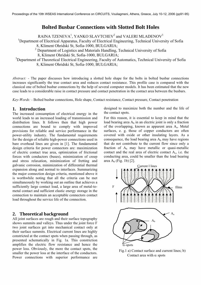
2. Theoretical background All joint surfaces are rough and their surface topography shows summits and valleys. Thus under the joint force F two joint surfaces get into mechanical contact only at their surface summits. Electrical current lines are highly constricted at the contact spots when passing through, as presented schematically in Fig. 1a. This constriction amplifies the electric flow resistance and hence the power loss. Obviously, the more the contact spots, the smaller the power loss at the interface of the conductors. Power connections with superior performance are
designed to maximize both the number and the life of the contact spots. For this reason, it is essential to keep in mind that the load bearing area Ab in an electric joint is only a fraction of the overlapping, known as apparent area Aa. Metal surfaces, e. g. those of copper conductors are often covered with oxide or other insulating layers. As a consequence, the load bearing area Ab may have regions that do not contribute to the current flow since only a fraction of Ab may have metallic or quasi-metallic contact and the real area of electric contact Ac, i.e. the conducting area, could be smaller than the load bearing area Ab (Fig. 1b) [2]. Current I lines F films Aa
Fig.1 a) Contact surface and current lines; b) Contact area with α spots
α-spots
Ab
Proceedings of the 10th WSEAS International Conference on CIRCUITS, Vouliagmeni, Athens, Greece, July 10-12, 2006 (pp91-95)
A conducting area is referred to as quasi-metallic when it is covered with a thin (< 20 Å) film that can be tunneled through by electrons. This quasi-metallic electric contact results in a relatively small film resistance RF. The summits of the two electric joint surfaces, being in metallic or quasi-metallic contact, form the so called α-spots where the current lines bundle together causing the constriction resistance Rc. The number n, the shape and the area of the α-spots are generally stochastic and depend on material parameters of the conductor material, the topography of the joint surfaces and the joint force. For simplicity it is often assumed that the α-spots are circular. Looking at one single circular α-spot its constriction resistance Rc depends on its radius a and the resistivity ρ of the conductor material. Under the assumption that the bulk material above and under the α-spot is infinite in volume, the value of the constriction resistance can be calculated by means of the Holm´s ellipsoid model.
aRc 2
ρ= (1)
If a single α-spot is completely covered with a thin film of resistivity ρf and thickness s, its film resistance Rf is given by
22 aa
sR ff
f π
σ=
π
ρ= (2)
where σf is the tunnel resistivity i.e. the resistance of the film across one cm². The total resistance R1 of a α-spot, referred to as contact resistance, results in the sum of the constriction resistance Rc and the film resistance Rf
fc RRR +=1 (3)
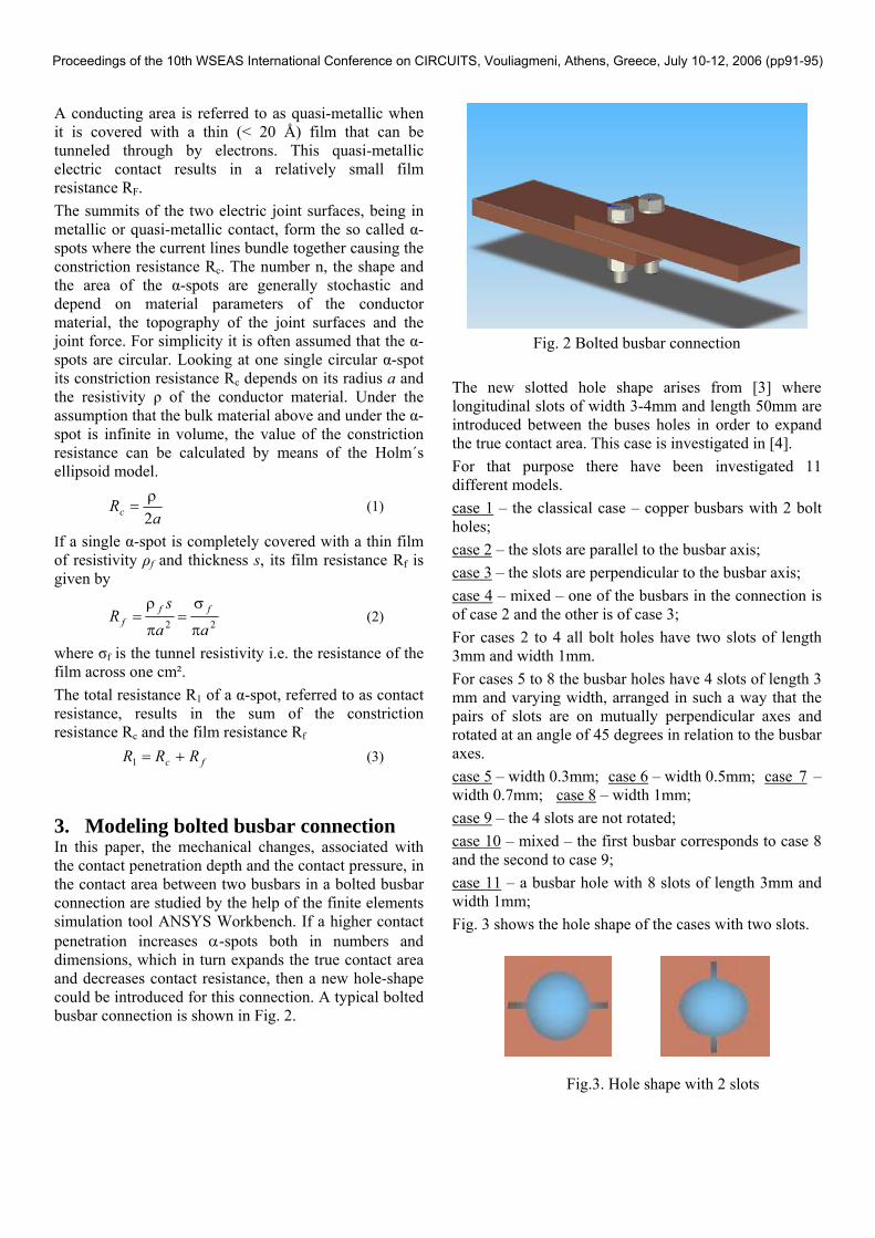
3. Modeling bolted busbar connection In this paper, the mechanical changes, associated with the contact penetration depth and the contact pressure, in the contact area between two busbars in a bolted busbar connection are studied by the help of the finite elements simulation tool ANSYS Workbench. If a higher contact penetration increases α-spots both in numbers and dimensions, which in turn expands the true contact area and decreases contact resistance, then a new hole-shape could be introduced for this connection. A typical bolted busbar connection is shown in Fig. 2.
Fig. 2 Bolted busbar connection
The new slotted hole shape arises from [3] where longitudinal slots of width 3-4mm and length 50mm are introduced between the buses holes in order to expand the true contact area. This case is investigated in [4]. For that purpose there have been investigated 11 different models. case 1 – the classical case – copper busbars with 2 bolt holes; case 2 – the slots are parallel to the busbar axis; case 3 – the slots are perpendicular to the busbar axis; case 4 – mixed – one of the busbars in the connection is of case 2 and the other is of case 3; For cases 2 to 4 all bolt holes have two slots of length 3mm and width 1mm. For cases 5 to 8 the busbar holes have 4 slots of length 3 mm and varying width, arranged in such a way that the pairs of slots are on mutually perpendicular axes and rotated at an angle of 45 degrees in relation to the busbar axes. case 5 – width 0.3mm; case 6 – width 0.5mm; case 7 – width 0.7mm; case 8 – width 1mm; case 9 – the 4 slots are not rotated; case 10 – mixed – the first busbar corresponds to case 8 and the second to case 9; case 11 – a busbar hole with 8 slots of length 3mm and width 1mm; Fig. 3 shows the hole shape of the cases with two slots.
Fig.3. Hole shape with 2 slots
Proceedings of the 10th WSEAS International Conference on CIRCUITS, Vouliagmeni, Athens, Greece, July 10-12, 2006 (pp91-95)
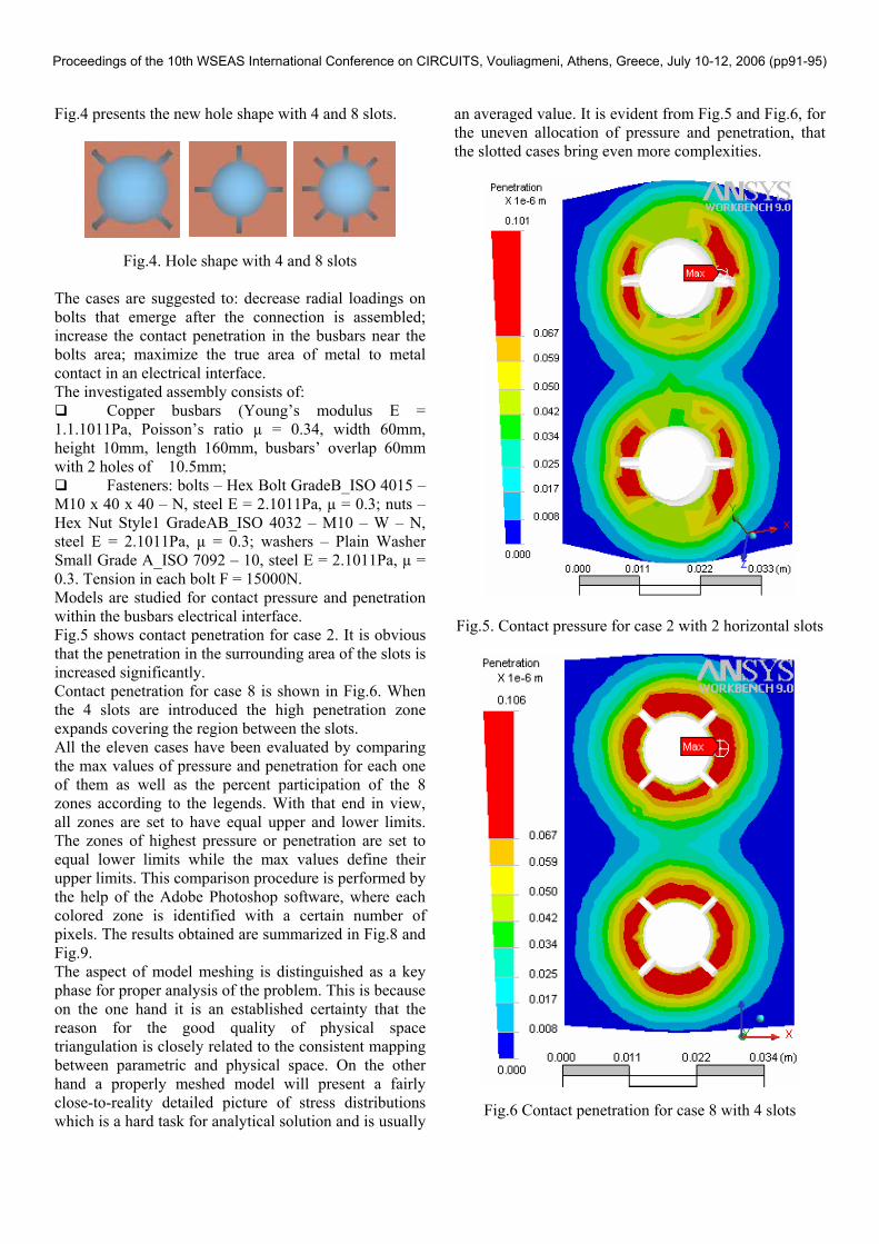
Fig.4 presents the new hole shape with 4 and 8 slots.
Fig.4. Hole shape with 4 and 8 slots The cases are suggested to: decrease radial loadings on bolts that emerge after the connection is assembled; increase the contact penetration in the busbars near the bolts area; maximize the true area of metal to metal contact in an electrical interface. The investigated assembly consists of:
Copper busbars (Young’s modulus Е = 1.1.1011Pa, Poisson’s ratio µ = 0.34, width 60mm, height 10mm, length 160mm, busbars’ overlap 60mm with 2 holes of �10.5mm;
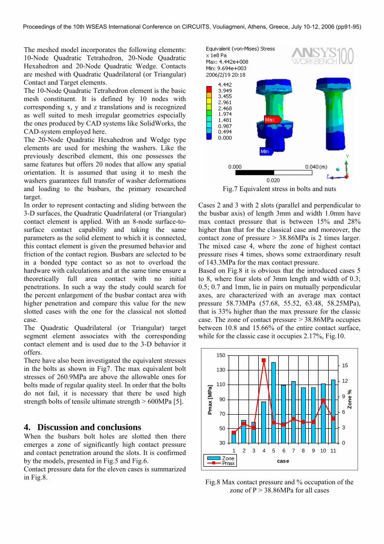
Fasteners: bolts – Hex Bolt GradeB_ISO 4015 – M10 x 40 x 40 – N, steel E = 2.1011Pa, µ = 0.3; nuts – Hex Nut Style1 GradeAB_ISO 4032 – M10 – W – N, steel E = 2.1011Pa, µ = 0.3; washers – Plain Washer Small Grade A_ISO 7092 – 10, steel E = 2.1011Pa, µ = 0.3. Tension in each bolt F = 15000N. Models are studied for contact pressure and penetration within the busbars electrical interface. Fig.5 shows contact penetration for case 2. It is obvious that the penetration in the surrounding area of the slots is increased significantly. Contact penetration for case 8 is shown in Fig.6. When the 4 slots are introduced the high penetration zone expands covering the region between the slots. All the eleven cases have been evaluated by comparing the max values of pressure and penetration for each one of them as well as the percent participation of the 8 zones according to the legends. With that end in view, all zones are set to have equal upper and lower limits. The zones of highest pressure or penetration are set to equal lower limits while the max values define their upper limits. This comparison procedure is performed by the help of the Adobe Photoshop software, where each colored zone is identified with a certain number of pixels. The results obtained are summarized in Fig.8 and Fig.9. The aspect of model meshing is distinguished as a key phase for proper analysis of the problem. This is because on the one hand it is an established certainty that the reason for the good quality of physical space triangulation is closely related to the consistent mapping between parametric and physical space. On the other hand a properly meshed model will present a fairly close-to-reality detailed picture of stress distributions which is a hard task for analytical solution and is usually
an averaged value. It is evident from Fig.5 and Fig.6, for the uneven allocation of pressure and penetration, that the slotted cases bring even more complexities.
Fig.5. Contact pressure for case 2 with 2 horizontal slots
Fig.6 Contact penetration for case 8 with 4 slots
Proceedings of the 10th WSEAS International Conference on CIRCUITS, Vouliagmeni, Athens, Greece, July 10-12, 2006 (pp91-95)
The meshed model incorporates the following elements: 10-Node Quadratic Tetrahedron, 20-Node Quadratic Hexahedron and 20-Node Quadratic Wedge. Contacts are meshed with Quadratic Quadrilateral (or Triangular) Contact and Target elements. The 10-Node Quadratic Tetrahedron element is the basic mesh constituent. It is defined by 10 nodes with corresponding x, y and z translations and is recognized as well suited to mesh irregular geometries especially the ones produced by CAD systems like SolidWorks, the CAD-system employed here. The 20-Node Quadratic Hexahedron and Wedge type elements are used for meshing the washers. Like the previously described element, this one possesses the same features but offers 20 nodes that allow any spatial orientation. It is assumed that using it to mesh the washers guarantees full transfer of washer deformations and loading to the busbars, the primary researched target. In order to represent contacting and sliding between the 3-D surfaces, the Quadratic Quadrilateral (or Triangular) contact element is applied. With an 8-node surface-to-surface contact capability and taking the same parameters as the solid element to which it is connected, this contact element is given the presumed behavior and friction of the contact region. Busbars are selected to be in a bonded type contact so as not to overload the hardware with calculations and at the same time ensure a theoretically full area contact with no initial penetrations. In such a way the study could search for the percent enlargement of the busbar contact area with higher penetration and compare this value for the new slotted cases with the one for the classical not slotted case. The Quadratic Quadrilateral (or Triangular) target segment element associates with the corresponding contact element and is used due to the 3-D behavior it offers. There have also been investigated the equivalent stresses in the bolts as shown in Fig7. The max equivalent bolt stresses of 260.9MPa are above the allowable ones for bolts made of regular quality steel. In order that the bolts do not fail, it is necessary that there be used high strength bolts of tensile ultimate strength > 600MPa [5]. 4. Discussion and conclusions When the busbars bolt holes are slotted then there emerges a zone of significantly high contact pressure and contact penetration around the slots. It is confirmed by the models, presented in Fig.5 and Fig.6. Contact pressure data for the eleven cases is summarized in Fig.8.
Fig.7 Equivalent stress in bolts and nuts
Cases 2 and 3 with 2 slots (parallel and perpendicular to the busbar axis) of length 3mm and width 1.0mm have max contact pressure that is between 15% and 28% higher than that for the classical case and moreover, the contact zone of pressure > 38.86MPa is 2 times larger. The mixed case 4, where the zone of highest contact pressure rises 4 times, shows some extraordinary result of 143.3MPa for the max contact pressure. Based on Fig.8 it is obvious that the introduced cases 5 to 8, where four slots of 3mm length and width of 0.3; 0.5; 0.7 and 1mm, lie in pairs on mutually perpendicular axes, are characterized with an average max contact pressure 58.73MPa (57.68, 55.52, 63.48, 58.25MPa), that is 33% higher than the max pressure for the classic case. The zone of contact pressure > 38.86MPa occupies between 10.8 and 15.66% of the entire contact surface, while for the classic case it occupies 2.17%, Fig.10.
30
50
70
90
110
130
150
1 2 3 4 5 6 7 8 9 10 11
case
Pmax
[MPa
]
0
3
6
9
12
15
Zone
%
ZonePmax
Fig.8 Max contact pressure and % occupation of the zone of P > 38.86MPa for all cases
Proceedings of the 10th WSEAS International Conference on CIRCUITS, Vouliagmeni, Athens, Greece, July 10-12, 2006 (pp91-95)
Case 9 with 4 not rotated crossed slots of width 1.0 mm is equivalent to case 8. The mixed case 10 is characterized with higher max contact pressure (88.04MPa). The results for the contact pressure of the last investigated case 11 with 8 slots of width 1mm are similar to those for cases 5 to 8. The results for the contact penetration are summarized in. Fig. 9.
0
0,05
0,1
0,15
0,2
0,25
0,3
1 2 3 4 5 6 7 8 9 10 11
case
µmax
[µm
]
0
3
6
9
12
15
18
21
24
Zone
%
Zoneµmax
Fig.9 Max contact penetration and % occupation of the zone of µ > 0.0673µm for all cases
2.17
15.66
11.3
12.06
10.8
12.32
1
5
6
7
8
11
case
zone,%
Fig.10 Percent occupation of the P > 38.86MPa zone for
cases 1, 5 to 8 and 11 For cases 2 and 3 the max contact penetration is about 0.1 µm, which is 33% higher compared with the classical case. The zone of highest contact penetration, >0.0673µm is 3 times larger than the same zone for the classic case. For the mixed case 4 the max contact penetration has an extraordinary value of 0.256µm again. The zone of highest contact penetration occupies 13.84% of the entire contact area, according to the model and this zone is 7 times larger than that for the classic case.
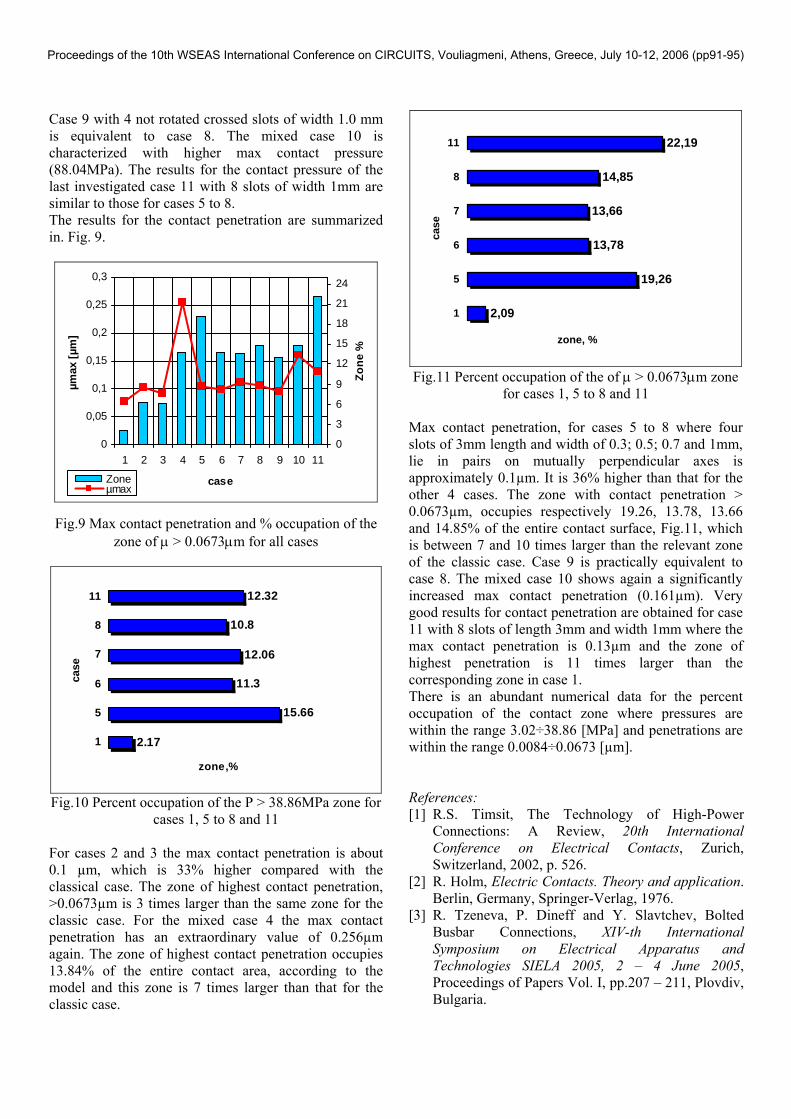
2,09
19,26
13,78
13,66
14,85
22,19
1
5
6
7
8
11
case
zone, %
Fig.11 Percent occupation of the of µ > 0.0673µm zone
for cases 1, 5 to 8 and 11 Max contact penetration, for cases 5 to 8 where four slots of 3mm length and width of 0.3; 0.5; 0.7 and 1mm, lie in pairs on mutually perpendicular axes is approximately 0.1µm. It is 36% higher than that for the other 4 cases. The zone with contact penetration > 0.0673µm, occupies respectively 19.26, 13.78, 13.66 and 14.85% of the entire contact surface, Fig.11, which is between 7 and 10 times larger than the relevant zone of the classic case. Case 9 is practically equivalent to case 8. The mixed case 10 shows again a significantly increased max contact penetration (0.161µm). Very good results for contact penetration are obtained for case 11 with 8 slots of length 3mm and width 1mm where the max contact penetration is 0.13µm and the zone of highest penetration is 11 times larger than the corresponding zone in case 1. There is an abundant numerical data for the percent occupation of the contact zone where pressures are within the range 3.02÷38.86 [MPa] and penetrations are within the range 0.0084÷0.0673 [µm]. References: [1] R.S. Timsit, The Technology of High-Power
Connections: A Review, 20th International Conference on Electrical Contacts, Zurich, Switzerland, 2002, p. 526.
[2] R. Holm, Electric Contacts. Theory and application. Berlin, Germany, Springer-Verlag, 1976.
[3] R. Tzeneva, P. Dineff and Y. Slavtchev, Bolted Busbar Connections, XIV-th International Symposium on Electrical Apparatus and Technologies SIELA 2005, 2 – 4 June 2005, Proceedings of Papers Vol. I, pp.207 – 211, Plovdiv, Bulgaria.
Proceedings of the 10th WSEAS International Conference on CIRCUITS, Vouliagmeni, Athens, Greece, July 10-12, 2006 (pp91-95)