boom cylinder removal - quality service manual
TRANSCRIPT

8004-5
BOOM CYLINDER
Removal
STEP 1
UA-08
Park the machine on a level surface. Lower the attachment to the ground.
STEP 2
Turn the starter switch to the OFF position to stop the engine.
STEP 3
Turn the starter switch to the ON position. Check that the CONTROLS LOCK symbol is not displayed on the systems display panel.
STEP 4
Operate the swing and attachments control levers back and forth, left and right ten times, to release hydraulic system pressure.
STEP 5
Turn the starter switch to the OFF position.
Rae 7-63000
STEP 6
At the top of the hydraulic reservoir, remove the cap from the breather. Push down on the button to release the air pressure in the hydraulic reservoir. Install the cap on the breather.
WARNING: Before doing any maintenance on the hydraulic system, make sure that all hydraulic pressure has been released by
~ operating the control levers several times and the hydraulic reservoir air pressure has been released. Failure to do so could cause serious injury. CSM120
STEP 7
Install a DO NOT OPERATE tag on the ignition key.
STEP 8
To prevent loss of hydraulic oil when disconnecting the hydraulic lines, connect a vacuum pump to the hydraulic reservoir. (See Section 8000.)
Issued 2-95 Printed in U.S.A.

8004-6
STEP 9
8004-03
Disconnect the lubrication hose from the boom cylinder.
NOTE: Lift the cylinder carefully. The cylinder is heavy and must be balanced by slings when lifting.
STEP 10
Attach a sling and a hoist to the boom cylinder. Take up all slack to provide support when removing the boom cylinder.
Rae 7-63000
STEP 11
Lock Ring
8004-05
Remove the four nuts securing the two cap screws. Remove the cap screws from the pin and lock rings. Drive the pin through far enough to clear the boom cylinder to be removed. Remove the shims and lock rings. Check the OD of the pin. Replace the pin if the OD is less than 3.310 inches (84 mm).
STEP 12
Place a stand in front of the boom cylinder. Lower the front end of the boom cylinder until it rests on the stand.
Issued 2-95 Printed in U.S.A.

STEP 13
Attach a suitable strap to the boom cylinder to hold the cylinder rod to the cylinder barrel.
STEP 14
Start the vacuum pump.
STEP 15
8004-09
Disconnect the hydraulic hoses from the fittings on the boom cylinder. Install plugs and caps on the hydraulic hoses and fittings. Shut off the vacuum pump.
Rae 7-63000
STEP 16
Nuts
8004-7
~
<::S~ ! Cap Screw
8004-13A
Remove the two nuts securing the cap screw. Remove the cap screw from the pin. Install the proper size cap screw in the threaded hole in the pin. Use a suitable slide hammer attached to the cap screw to remove the pin. Remove the cap screw from the pin. Check the OD of the pin. Replace the pin if the OD is less than 3.113 inches (79 mm).
STEP 17
Carefully lift the boom cylinder up and away from the machine. Place the boom cylinder on suitable supports. Remove the strap securing the cylinder rod to the cylinder barrel.
STEP 18
Repeat steps 9 through 17 to remove the remaining boom cylinder from the other side of the boom.
Issued 2-95 Printed in U.S.A.

8004-8
Installation
m Cylinder Boo H draulic Hose 6. y 7 Lubrication Hose 7. Nut
2. Nut 8. Cap Screw
a: Cap Screw 9. Pin Cylinder 4. Lock Rmg 1 o. Boom 5. Shim
Rae 7-63000 Issued 2-9S Printed in U.S.A.

STEP 1
8004-25
Attach a suitable strap to the boom cylinder to hold the cylinder rod to the cylinder barrel.
NOTE: Lift the cylinder carefully. The cylinder is heavy and must be balanced by slings when lifting.
STEP 2
With a sling and a hoist attached, lift the boom cylinder. Align the boom cylinder with the mounting brackets on the main frame of the machine. Support the outer end of the boom cylinder on a suitable stand.
Rae 7-63000
STEP 3
8004-9
Cap Screw
8004-13
Install the pin through the mounting bracket and boom cylinder by driving the pin in. Secure the pin with the cap screw. Using a feeler gauge, check that the clearance between the mounting bracket and the cylinder tube mounting eye is between 0.039 to 0.098 inch (1 to 2.5 mm). If necessary, remove the cap screw and pin and add shim(s) as necessary to obtain the correct clearance. Install the pin and cap screw. Install first nut on the cap screw and tighten until the nut makes contact with the boss on the mounting bracket. Back off the nut 1/4 turn and using two wrenches, install the second nut to secure the first nut in place.
NOTE: Once installed, the cap screw will have approximately 1/16 inch {1.6 mm) offree play.
Issued 2-95 Printed in U.S.A.

8004-10
STEP 4
Start the vacuum pump. Remove the plugs and caps from the hydraulic hoses and fittings. Connect the two hydraulic hoses to the boom cylinder fittings. Shut off the vacuum pump. Remove the strap securing the cylinder rod to the cylinder barrel.
STEP 5
Lift the boom cylinder and align the rod end of the cylinder with the mounting hole in the boom.
STEP 6
Repeat steps 1 through 5 to place the second boom cylinder on the opposite side of the boom into position.
Rae 7-63000
STEP 7
8004·16
Install the pin through the cylinder, shim, boom, shim, and second boom cylinder.
STEP 8
Install the shims on both ends of the pin. Install the lock rings on both ends of the pin. Install the two cap screws through the lock rings and pins. Using a feeler gauge, check that the clearance between the mounting bracket and the cylinder rod mounting eye is between 0.039 to 0.098 inch (1 to 2.5 mm). If necessary, remove the cap screw and pin and add or remove shim(s) as necessary to obtain the correct clearance. Install the pin and cap screw. Install first nut on the cap screw and tighten until the nut makes contact with the lock ring. Back off the nut 1/4 turn and using two wrenches, install the second nut to secure the first nut in place. Remove the sling and hoist from the boom cylinder.
NOTE: Once installed, the cap screw will have approximately 1/16 inch (1.6 mm) of free play.
Issued 2-95 Printed in U.S.A.

STEP 9
8004-18
Connect the lubrication hose to the boom cylinder.
Rae 7-63000
8004-11
STEP 10
Remove the DO NOT OPERATE tag from the ignition key.
STEP 11
Refer to Section 8000 and disconnect the vacuum pump. Start the engine and operate the boom cylinders to release any entrapped air. Check the boom cylinders for oil leakage. Stop the engine and shut down the machine.
Issued 2-95 Printed in U.S.A.

8004-12
ARM CYLINDER
Removal
STEP 1
UA-08
Park the machine on a level surface. Lower the attachment to the ground.
STEP 2
Turn the starter switch to the OFF position to stop the engine.
STEP 3
Turn the starter switch to the ON position. Check that the CONTROLS LOCK symbol is not displayed on the systems display panel.
STEP 4
Operate the swing and attachments control levers back and forth, left and right ten times, to release hydraulic system pressure.
STEP 5
Turn the starter switch to the OFF position.
Rae 7-63000
STEP 6
At the top of the hydraulic reservoir, remove the cap from the breather. Push down on the button to release the air pressure in the hydraulic reservoir. Install the cap on the breather.
WARNING: Before doing any maintenance on the hydraulic system, make sure that all hydraulic pressure has been released by
~ operating the control levers several times • and the hydraulic reservoir air pressure has
been released. Failure to do so could cause serious injury. CSM120
STEP 7
Install a DO NOT OPERATE tag on the ignition key.
STEP 8
To prevent loss of hydraulic oil when disconnecting the hydraulic lines, connect a vacuum pump to the hydraulic reservoir. (See Section 8000.)
Issued 2-95 Printed in U.S.A.

STEP 9
8004-21
Place a wood block under the arm cylinder.
STEP 10
8004-23
Remove the two nuts and cap screw from the pin securing the cylinder rod end.
STEP 11
8004-24
Carefully drive the pin from the arm and arm cylinder. Check the OD of the pin. Replace the pin if the OD is less than 3.113 inches {79 mm).
Rae 7-63000
8004-13
STEP 12
8004-25
Attach a suitable strap to the arm cylinder to hold the cylinder rod to the cylinder barrel.
STEP 13
Start the vacuum pump.
STEP 14
Disconnect the two hydraulic hoses from the fittings on the arm cylinder. Install plugs and caps on the hydraulic hoses and fittings. Shut off the vacuum pump.
STEP 15
Disconnect the lubrication hose from the arm cylinder.
Issued 2-95 Printed in U.S.A.

8004-14
NOTE: Lift the cylinder carefully. The cylinder is heavy and must be balanced by slings when lifting.
STEP 16 Wood Block
8004-28
Attach a sling and hoist to the arm cylinder. Take up all slack to provide support when removing the arm cylinder.
STEP 17
Cap Screw 8004-29
Remove the two nuts and cap screw from the pin securing the cylinder tube end. Drive the pin from the boom and the arm cylinder. Check the OD of the pin. Replace the pin if the OD is less than 3.113 inches {79 mm).
Rae 7-63000
STEP 18
Carefully lift the arm cylinder up and away from the arm. Remove the two shims from both sides of the arm cylinder. Place the arm cylinder on suitable supports.
NOTE: Remove wood block as weight is lifted from the arm cylinder.
STEP 19
8004-25
Remove the strap securing the cylinder rod to the cylinder barrel.
Issued 2-95 Printed in U.S.A.

Rae 7-63000
Installation
Arm Cylinder
1. Nut 2· C?P Screw 3. Pm 4. Hydraulic Hose 5. Lubrication Hose
6. Nut 7· Cap Screw B. Pin
190. Arm Cylinder ·Shim
8004-15
8004-77
Issued 2-95 Printed in U.S.A.
8004-16
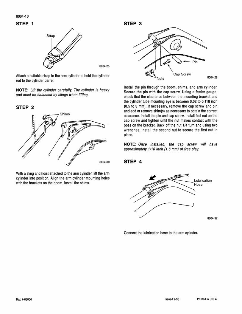
STEP 1
8004-25
Attach a suitable strap to the arm cylinder to hold the cylinder rod to the cylinder barrel.
NOTE: Lift the cylinder carefully. The cylinder is heavy and must be balanced by slings when lifting.
STEP 2
With a sling and hoist attached to the arm cylinder, lift the arm cylinder into position. Align the arm cylinder mounting holes with the brackets on the boom. Install the shims.
Rae 7-63000
STEP 3
8004-29
Install the pin through the boom, shims, and arm cylinder. Secure the pin with the cap screw. Using a feeler gauge, check that the clearance between the mounting bracket and the cylinder tube mounting eye is between 0.02 to 0.118 inch (0.5 to 3 mm). If necessary, remove the cap screw and pin and add or remove shim(s) as necessary to obtain the correct clearance. Install the pin and cap screw. Install first nut on the cap screw and tighten until the nut makes contact with the boss on the bracket. Back off the nut 1/4 turn and using two wrenches, install the second nut to secure the first nut in place.
NOTE: Once installed, the cap screw will have approximately 1/16 inch (1.6 mm) of free play.
STEP 4
Connect the lubrication hose to the arm cylinder.
Issued 2-95 Printed in U.S.A.

STEP 5
Start the vacuum pump. Remove the plugs and caps from the hydraulic hoses and fittings. Connect the hydraulic hoses to the arm cylinder fittings. Shut off the vacuum pump.
STEP 6
8004-25
Remove the strap securing the cylinder rod to the cylinder barrel.
STEP 7
8004·34
Hoist the end of the arm cylinder to align the cylinder head to the end of the arm.
Rae 7-63000
8004-17
STEP 8
8004·35
Install the pin through the arm and end of the arm cylinder. Install the cap screw to secure the cylinder. Using a feeler gauge, check that the clearance between the mounting bracket and the cylinder rod mounting eye is between 0.02 to 0.118 inch (0.5 to 3 mm). If necessary, remove the cap screw and pin and add or remove shim(s) as necessary to obtain the correct clearance. Install the pin and cap screw. Install first nut on the cap screw and tighten until the nut makes contact with the boss. Back off the nut 1/4 turn and using two wrenches, install the second nut to secure the first nut in place. Remove the sling and hoist from the arm cylinder.
NOTE: Once installed, the cap screw will have approximately 1/16 inch (1.6 mm) of free play.
STEP 9
Remove the DO NOT OPERATE tag from the ignition key.
STEP 10
Refer to Section 8000 and disconnect the vacuum pump. Start the engine and operate the arm cylinder to release any entrapped air. Check the arm cylinder for oil leakage. Stop the engine and shut down the machine.
Issued 2-95 Printed in U.S.A.

8004-18
BUCKET CYLINDER
Removal
STEP 1
UA-08
Park the machine on a level surface. Lower the attachment to the ground.
STEP 2
Turn the starter switch to the OFF position to stop the engine.
STEP 3
Turn the starter switch to the ON position. Check that the CONTROLS LOCK symbol is not displayed on the systems display panel.
STEP 4
Operate the swing and attachments control levers back and forth, left and right ten times, to release hydraulic system pressure.
STEP 5
Turn the starter switch to the OFF position.
Rae 7-63000
STEP 6
At the top of the hydraulic reservoir, remove the cap from the breather. Push down on the button to release the air pressure in the hydraulic reservoir. Install the cap on the breather.
WARNING: Before doing any maintenance on the hydraulic system, make sure that all hydraulic pressure has been released by
~ operating the control levers several times and the hydraulic reservoir air pressure has been released. Failure to do so could cause serious injury. CSM120
STEP 7
Install a DO NOT OPERATE tag on the ignition key.
STEP 8
To prevent loss of hydraulic oil when disconnecting the hydraulic lines, connect a vacuum pump to the hydraulic reservoir. (See Section 8000.)
Issued 2-95 Printed in U.S.A.

STEP 9
8004-38
Place a wood block under the bucket cylinder.
NOTE: Lift the cylinder carefully. The cylinder is heavy and must be balanced by slings when lifting.
STEP 10
8004-80
Attach a sling and hoist to the bucket cylinder. Take up all slack to provide support when removing the bucket cylinder.
STEP 11
Remove the two nuts from the cap screw, and remove the cap screw from the link and pin.
Rae 7-63000
8004-19
STEP 12
Pin~
' ~
8004-41
Carefully drive the pin from the links and bucket cylinder. Check the OD of the pin. Replace the pin if the OD is less than 3.310 inches (84 mm).
STEP 13
8004-42
Lift the bucket cylinder away from the links. Attach a suitable strap to the bucket cylinder to hold the cylinder rod to the cylinder barrel. Remove the two shims.
NOTE: Remove the wood block as the bucket cylinder is lifted.
STEP 14
8004-43
Start the vacuum pump. Disconnect the two hydraulic hoses from the fittings on the upper end of the bucket cylinder. Install plugs and caps on the hydraulic hoses and the fittings. Shut off the vacuum pump.
Issued 2-95 Printed in U.S.A.

8004-20
STEP 15
~Pin
~' Q I~
~N~s 8004-45
Remove the two nuts from the cap screw. Remove the cap screw from the pin and arm. Drive the pin from the arm and the bucket cylinder. Check the OD of the pin. Replace the pin if the OD is less than 2.916 inches (74 mm).
STEP 16
Carefully lift the bucket cylinder up and away from the arm. Remove the two shims from both sides of the bucket cylinder. Place the bucket cylinder on suitable supports. Remove lifting sling and hoist from the bucket cylinder.
Rae 7·63000
STEP 17
8004-25
Remove the strap securing the cylinder rod to the cylinder barrel.
Issued 2·95 Printed in U.S.A.

Rae 7-63000
Installation
Bucket Cylinder
1. Nut 2. Cap Screw 3. Pin 4. Shim 5. Hydraulic Hose 6. Nut
7. Cap Screw B. Pin 9. Shim 10. Bucket Cylinder 11. Link
8004-21
Issued 2-95 Printed in U.S.A.

8004-22
STEP 1
8004-25
Attach a suitable strap to the bucket cylinder to hold the cylinder rod to the cylinder barrel.
NOTE: Lift the cylinder carefully. The cylinder is heavy and must be balanced by slings when lifting.
STEP 2
Install the shims on each side of the cylinder. With a sling and hoist attached, lower the bucket cylinder into position on the arm.
Rae 7-63000
STEP 3
~Pin
~ '
8004-47
With the cylinder and shims in position, drive the pin through the arm, shims, and cylinder. Install the cap screw through the boss on the arm and pin. Using a feeler gauge, check that the clearance between the mounting bracket and the cylinder tube mounting eye is between 0.02 to 0.118 inch (0.5 to 3 mm). If necessary, remove the cap screw and pin and add or remove shim(s) as necessary to obtain the correct clearance. Install the pin and cap screw. Install first nut on the cap screw and tighten until the nut makes contact with the boss. Back off the nut 1/4 turn and using two wrenches, install the second nut to secure the first nut in place.
NOTE: Once installed, the cap screw will have approximately 1/16 inch (1.6 mm) of free play.
STEP 4
8004-48
Start the vacuum pump. Remove the plugs and caps from the hydraulic hoses and fittings. Connect the hydraulic hoses to the bucket cylinder fittings. Shut off the vacuum pump.
Issued 2-95 Printed in U.S.A.

STEP 5
8004-25
Remove the strap securing the cylinder rod to the cylinder barrel.
STEP 6
Raise the bucket cylinder to align the cylinder rod with the links. Install two shims in line with the link mounting holes.
Rae 7-63000
8004-23
STEP 7
8004-50
Drive the pin through the links, shims, and the bucket cylinder. Install the cap screw through the boss on the link and pin. Using a feeler gauge, check that the clearance between the link and the cylinder rod mounting eye is between 0.039 to 0.079 inch {1 to 2 mm). If necessary, remove the cap screw and pin and add or remove shim{s) as necessary to obtain the correct clearance. Install the pin and cap screw. Install first nut on the cap screw and tighten until the nut makes contact with the boss. Back off the nut 1/4 turn and using two wrenches, install the second nut to secure the first nut in place. Remove the sling and hoist from the bucket cylinder.
NOTE: Once installed, the cap screw will have approximately 1/16 inch (1.6 mm) of free play.
STEP 8
Remove the DO NOT OPERATE tag from the ignition key.
STEP 9
Refer to Section 8000 and disconnect the vacuum pump. Start the engine and operate the bucket cylinder to release any entrapped air. Check the bucket cylinder for oil leakage. Stop the engine and shut down the machine.
Issued 2-95 Printed in U.S.A.

8004-24
CYLINDERS
Disassembly
NOTE: The boom, arm, and bucket cylinders are basically identical in construction. The major differences are in the attachment of the hydraulic tubes on the outside of the cylinders. Before installing the cylinder in the repair stand, remove the tubes.
STEP 1 Boom Cylinder
NOTE: The numbers in parentheses in the following steps refer to the Boom Cylinder illustration on page 34.
1. Remove the lubrication fitting (1) from the cylinder.
2. Remove the two plugs (2). Remove and discard the two 0-rings (3).
3. Remove the eight socket head cap screws (4) and disconnect the hydraulic tubes (5 and 1 0) from the cylinder. Remove and discard the two 0-rings (6).
4. Remove the cap screw (7) and lock washer (8). Remove the clamp (9) from the tubes. Remove the hydraulic tubes (5 and 1 0) from the cylinder.
5. Remove the two cap screws (11) and washers (12), and remove clamp (13) from the cylinder.
STEP 2 Arm Cylinder
NOTE: The numbers in parentheses in the following steps refer to the Arm Cylinder illustration on page 35.
1. Remove the lubrication fitting (1) from the cylinder.
2. Remove the plug (2) from the hydraulic tube. Remove and discard the 0-ring (3).
3. Remove the eight socket head cap screws (4) and disconnect the two hydraulic tubes (5) from the cylinder. Remove and discard the two 0-rings (6).
4. Remove the cap screw (7) and lock washer (8), and remove the clamp (9) from the cylinder.
5. Remove the cap screw (11) and lock washer (12). Remove the clamp (13) from the cylinder. Remove the hydraulic tubes (5) from the cylinder.
Rae 7-63000
STEP 3 Bucket Cylinder
NOTE: The numbers in parentheses in the following steps refer to the Bucket Cylinder illustration on page 36.
1. Remove the two lubrication fittings (1) from the cylinder.
2. Remove the eight socket head cap screws (4). Disconnect the hydraulic tube (5) from the cylinder. Remove and discard the two 0-rings (6).
3. Remove the cap screw (7) and lock washer (8), and remove the clamp (9) from the cylinder.
4. Remove the cap screw (11) and washer (12), and remove the clamp (13) from the cylinder. Remove the hydraulic tube (5) from the cylinder.
STEP 4
Install the bushings in the tail stock chuck wings.
STEP 5
Tighten the setscrews to secure the bushings in the chuck wings.
Issued 2-95 Printed in U.S.A.