boom truck crane bt 3870 data sheet - imperial … bt3870 boom truck crane... · sale and terex...
TRANSCRIPT

BOOM TRUCK CRANEBT 3870
DATA ShEET - IMpERIAl
Features:
Capacityatrateddistancefromcenterofrotation:
19T@5ft
Maximumboomlength:
70ft
Maximumtipheight:
80ft
OptionalSingleStage24ftor24-40ftJib
120ftMaximumSheaveHeightwith40ftJib
BehindCabMountingwithEnhancedDualOperatorConsole
ElectronicLoadMomentIndicatorwithWorkAreaDefinition
QuickReevingDualSheaveBoomHead
BT 3870

CONTENTS
DimensionsCrane Dimensions . . . . . . . . . . . . . . . . . . . . . . . . . . . . . . . . . . . . . . . . . . . . . . . . . . . . . . . . . . . . . . . . . . . . . . 4Mounting Configurations . . . . . . . . . . . . . . . . . . . . . . . . . . . . . . . . . . . . . . . . . . . . . . . . . . . . . . . . . . . . . . . . . . . . . . . . . . . 5Area of Operation . . . . . . . . . . . . . . . . . . . . . . . . . . . . . . . . . . . . . . . . . . . . . . . . . . . . . . . . . . . . . . . . . . . . . . . . . . . . . . . . . . 5General Notes . . . . . . . . . . . . . . . . . . . . . . . . . . . . . . . . . . . . . . . . . . . . . . . . . . . . . . . . . . . . . . . . . . . . . . . . . . . . . . . . . . . . . . 5
load ChartsRange Diagram — BT 3870S . . . . . . . . . . . . . . . . . . . . . . . . . . . . . . . . . . . . . . . . . . . . . . . . . . . . . . . . . . . . . . 6Load Charts — BT 3870S . . . . . . . . . . . . . . . . . . . . . . . . . . . . . . . . . . . . . . . . . . . . . . . . . . . . . . . . . . . . . . . . . . . . . . . . . . . . 7Range Diagram — BT 3870T . . . . . . . . . . . . . . . . . . . . . . . . . . . . . . . . . . . . . . . . . . . . . . . . . . . . . . . . . . . . . . . . . . . . . . . . . 8Load Charts — BT 3870T. . . . . . . . . . . . . . . . . . . . . . . . . . . . . . . . . . . . . . . . . . . . . . . . . . . . . . . . . . . . . . . . . . . . . . . . . . . . . 9
Technical DescriptionBoom, Jib and Rotation . . . . . . . . . . . . . . . . . . . . . . . . . . . . . . . . . . . . . . . . . . . . . . . . . . . . . . . . . . . . . . . . . 10Hoist, Rope and Hook Block . . . . . . . . . . . . . . . . . . . . . . . . . . . . . . . . . . . . . . . . . . . . . . . . . . . . . . . . . . . . . 10Operator Controls, Operator Aids and Load Limiter/Load Indicator . . . . . . . . . . . . . . . . . . . . . . . . . . . 11Understructure and Hydraulic System . . . . . . . . . . . . . . . . . . . . . . . . . . . . . . . . . . . . . . . . . . . . . . . . . . . . . 11Optional Features . . . . . . . . . . . . . . . . . . . . . . . . . . . . . . . . . . . . . . . . . . . . . . . . . . . . . . . . . . . . . . . . . . . . . . 11
Page:
Key . . . . . . . . . . . . . . . . . . . . . . . . . . . . . . . . . . . . . . . . . . . . . . . . . . . . . . . . . . . . . . . . . . . . . . . . . . . . . . . . . . . 3
2

BT 3870KEY
3
Mainboom Hookblock
Boomlength Operatoraids/Loadlimiter/Loadindicator
Tipheight Hydraulics
Boomwithextension Telescopingmode
Mainboomwithauxhead Boomelevationangle
Slewing/Allowableslewingrange Workingradius
Outriggers/Liftingonoutriggers(100%/50%/0%extended)
Minimumdistancefromthehooktotheheadsheavepin
Mainhoist Ropelength
Hoistspeed Linepull
Rope–Standard/Optional Controls
Ropediameter Workingtemperature

BT 3870T
BT 3870S
DIMENSIONS
4

Area of Operation
BT 3870
5
MOUNTING CONFIGURATIONS
Gross Vehicle Weight Rating 33,000 lbFront Axle Weight Rating 12,000 lbRear Axle Weigh Rating 21,000 lbWheelbase 242 inCab to Axle 168 inAfterframe 100 inFrame Section Modulus 16.98 in3RBM per Frame Rail 1,800,000 lb-inFrame Height (Unloaded) 40 inExhaust Position Left Side Under Cab
Gross Vehicle Weight Rating 33,000 lbFront Axle Weight Rating 12,000 lbRear Axle Weigh Rating 21,000 lbWheelbase 242 inCab to Axle 168 inAfterframe 100 inFrame Section Modulus 16.98 in3RBM per Frame Rail 1,800,000 lb-inFrame Height (Unloaded) 40 inExhaust Position Left Side Under Cab
BT 3870S
BT 3870T
DEDUCTIONS FROM RATEDLOADS FOR LOAD
HANDLING DEVICES
OVERHAUL BALL:125 LBS STD WIRE ROPE250 LBS OPT WIRE ROPE1 SHEAVE LOAD BLOCK:
200 LBS.2 SHEAVE LOAD BLOCK:
260 LBS.

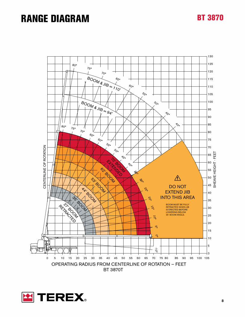
BT 3870RANGE DIAGRAM
70
OPERATING RADIUS FROM CENTERLINE OF ROTATION — FEETBT 3870S
50 201510 353025 5040 45 6055 65 858075 95 10090 105
5
0
20
15
10
CE
NTE
RLI
NE
OF
RO
TATI
ON
SH
EA
VE
HE
IGH
T - F
EE
T
35
25
30
40
45
50
55
60
70
65
75
105
90
85
80
100
95
110
115
120
125
130
DO NOTEXTEND JIB
INTO THIS AREABOOM MUST BE FULLYRETRACTED WHEN JIB IS ERECTED BEFORE LOWERING BELOW35˚ BOOM ANGLE.
BOOM & JIB = 110'
70' BOO
M
EXTENDED
27' BOO
M
RETRACTED
62' BOO
M53' BOO
M44' BOO
M
35' BOO
M
BOOM & JIB = 94'
80° 75°70°
65°60°
55°50°
45°
40°
80°75°
70°
65°
60°
55°
50°
45°
40°
5°10°
-10°15°
20°
25°
0°
35°30°
6

7
lOAD ChARTS
BT 3870S
BT 3870S
Jib Capacities for all Boom Lengths
35˚ 40˚ 45˚ 50˚ 55˚ 60˚ 65˚ 70˚ 75˚ 80˚
lb lb lb lb lb lb lb lb lb lb24 ft Jib 900 1,100 1400 1,700 1,900 2,100 2,500 3,200 3,600 3,90040 ft Jib 600 800 900 1,100 1,300 1,500 1,900 2,000 2,100 2,200
Lifting capacities do not exceed 85% of tipping load. Weight of hook blocks and slings is part of the load, and is to be deducted from the capacity ratings. Consult crane operation manual for additional details.
Data published herein is intended as a guide only and shall not be construed to warrantapplicability for lifting purposes.
Boom Length (ft)
27 35 44 53 62 70
ft lb lb lb lb lb lb ft5 38,000 58 26,400 8
10 22,200 21,200 20,500 1012 19,300 18,400 17,700 17,200 1215 16,200 15,400 14,700 14,300 13,900 12,000 1520 12,600 12,100 11,600 11,100 10,800 10,500 2025 9,200 9,700 9,500 9,100 8,800 8,600 2530 6,700 7,100 7,200 7,300 7,200 3035 5,200 5,400 5,500 5,600 3540 4,000 4,200 4,300 4,400 4045 3,300 3,400 3,500 4550 2,600 2,700 2,800 5055 2,200 2,300 5560 1,800 1,900 6065 1,500 65
Level Boom Capacities 6,900 5,100 3,500 2,400 1,700 1,300 Level Boom Capacities
100% ASME StandardB 30.527 to 70 ft
BT 3870RANGE DIAGRAM
8
70
OPERATING RADIUS FROM CENTERLINE OF ROTATION — FEETBT 3870T
50 201510 353025 5040 45 6055 65 858075 95 10090 105
5
0
20
15
10
CE
NTE
RLI
NE
OF
RO
TATI
ON
SH
EA
VE
HE
IGH
T - F
EE
T
35
25
30
40
45
50
55
60
70
65
75
105
90
85
80
100
95
110
115
120
125
130
DO NOTEXTEND JIB
INTO THIS AREABOOM MUST BE FULLYRETRACTED WHEN JIB IS ERECTED BEFORE LOWERING BELOW35˚ BOOM ANGLE.
BOOM & JIB = 110'
70' BOO
M
EXTENDED
27' BOO
M
RETRACTED
62' BOO
M53' BOO
M44' BOO
M
35' BOO
M
BOOM & JIB = 94'
80° 75°70°
65°60°
55°50°
45°
40°
80°75°
70°
65°
60°
55°
50°
45°
40°
5°10°
-10°15°
20°
25°
0°
35°30°

9
lOAD ChARTS
BT 3870T
BT 3870T
Boom Length (ft)
27 35 44 53 62 70
ft lb lb lb lb lb lb ft5 38,000 58 26,400 8
10 22,200 21,200 20,500 1012 19,300 18,400 17,700 17,200 1215 16,200 15,400 14,700 14,300 13,900 12,000 1520 12,600 12,100 11,600 11,100 10,800 10,500 2025 9,200 9,900 9,500 9,100 8,800 8,600 2530 8,000 8,000 7,700 7,400 7,200 3035 6,800 6,600 6,400 6,200 3540 5,400 5,700 5,600 5,400 4045 4,600 4,800 4,800 4550 3,800 3,900 3,900 5055 3,200 3,300 5560 2,600 2,800 6065 2,400 65
Level Boom Capacities 6,900 5,100 4,000 3,100 2,400 1,900 Level Boom Capacities
100% ASME StandardB 30.527 to 70 ft
Jib Capacities for all Boom Lengths
35˚ 40˚ 45˚ 50˚ 55˚ 60˚ 65˚ 70˚ 75˚ 80˚
lb lb lb lb lb lb lb lb lb lb24 ft Jib 1,300 1,400 1,500 1,700 1,900 2,100 2,500 3,200 3,600 3,90040 ft Jib 700 800 900 1,100 1,300 1,500 1,900 2,000 2,100 2,200
Lifting capacities do not exceed 85% of tipping load. Weight of hook blocks and slings is part of the load, and is to be deducted from the capacity ratings. Consult crane operation manual for additional details.
Data published herein is intended as a guide only and shall not be construed to warrantapplicability for lifting purposes.

TEChNICAl DESCRIpTION
Boom, Jib and Rotation
Three-section full power fully synchronized telelscopic keel boom 70 ft
Boom length 28-70 ft
Boom maximum tip height 80 ft
Boom elevation angle range (min / max).Boom up/down timeBoom extension / retraction time.
-10 to 80°25/16 seconds61/29 seconds
Boom head Quick reeving dual sheave boom head
Maximum tip height: boom with optional single stage 24 ft jib Maximum tip height: boom with optional two stage 24-40 ft jib
104 ft120 ft
180 degree standard rotation370 degree or continuous rotation (optional - requires single front bumber outrigger)
hoist, Rope and hook BlockPlanetary winch with “in-lever” 2-speed operation 150/220 ft/min
Hoist speed2-speed operation 150/220 ft/min
Rotation-resistant rope
Rope diameter
Breaking strength (use only 9/16 in diameter cable)Permissible line pull
46,000 lbs11,400 lbs
Minimum breaking strengthPermissible line pull
Overhaul ball1 Sheave block2 Sheave block
7 T17.5 T
25 T
1 part line2 part line3 part line4 part line
9,700 lbs/220 ft/min19,400 lbs/110 ft/min
29,100 lbs/73 ft/min38,000 lbs/55 ft/min
10

BT 3870TEChNICAl DESCRIpTION
Operator Controls, Operator Aids and load limiter/load IndicatorFully proportional, excellent metering characteristics for precise boom movements. Independent outrigger controls allow the crane to be stable and level in rigorous working conditions.
Foot pedals (in both operator station) for engine throttle and service brake.System has audio alarm and functional shut down when operator encounters an overload situation.
Electronic load indicator and limiter and work area defintion to setup working space limits.
Understructure and hydraulic SystemFront outriggers are Link-Type Maximum width over the main outrigger pad Main outrigger spread at maximum ground penetration
Rear outriggers are A-Frame type Maximum width over auxiliary outrigger pads
22 ft21 ft 6 in
10 ft 2 in
Hydraulic hoist with gear motor and planetary reduction gearing provides 2-speed operation Winch capacity Boom capacity Swing capacity
32 gal/min17 gal/min 8 gal/min
Dual outrigger controls on both sides of the carrier.
Optional Features• Single and two-stage jibs• Multi-part load blocks• Main winch with 2 speed motor• Heavy duty wood flatbeds• Extra heavy duty wood flatbeds• Extra heavy duty steel flatbeds• Radio remote controls• One-man or two-man baskets• Self-leveling work platform• Hoist drum tensioner• Continuous rotation• Oil cooler• Single front bumper outrigger (required for 370˚ or continuous rotation)• Hydraulic hose reel• Tool box• Inching control for hoist operation at rear of subframe, for one man hook ball stowage and deploy
11

www.terexcranes.com
Effective Date: October 2010. Product specifications and prices are subject to change without notice or obligation. The photographs and/or drawings in this document are for illustrative purposes only. Refer to the appropriate Operator’s Manual for instructions on the proper use of this equipment. Failure to follow the appropriate Operator’s Manual when using our equipment or to otherwise act irresponsibly may result in serious injury or death. The only warranty applicable to our equipment is the standard written warranty applicable to the particular product and sale and Terex makes no other warranty, express or implied. Products and services listed may be trademarks, service marks or trade-names of Terex Corporation and/or its subsidiaries in the USA and other countries. All rights are reserved. Terex is a registered trademark of Terex Corporation in the USA and many other countries. Copyright © 2010 Terex Corporation.
Terex Cranes, Global Marketing, Dinglerstraße 24, 66482 Zweibrücken, Germany Tel. + 49 (0) 6332 830, Email: [email protected], www.terexcranes.com
TC-DS-I-E-BT 3870-10/10