borated polyethylene - lund university...
TRANSCRIPT

Borated polyethylene - fire properties and other issues Dan Madsen Department of Fire Safety Engineering and Systems Safety Lund University, Sweden Brandteknik och Riskhantering Lunds tekniska högskola Lunds universitet Report 5443, Lund 2014
The report was funded by ESS AB


3
Borated polyethylene - fire properties and other issues
Dan Madsen
Lund 2014

4
Borated polyethylene - fire properties and other issues Dan Madsen Report 5443 ISSN: 1402-3504 ISRN: LUTVDG/TVBB-5443-SE Number of pages: 68 Keywords Cone calorimeter, Conetools, borated polyethylene, fire properties, radiation shielding
The author is responsible for the content in the report
© Copyright: Brandteknik och Riskhantering, Lunds tekniska högskola, Lunds universitet, Lund 2014.
Department of Fire Safety Engineering and Systems Safety
Lund University P.O. Box 118
SE-221 00 Lund Sweden
[email protected] http://www.brand.lth.se/english
Telephone: +46 46 222 73 60 Fax: +46 46 222 46 12
Brandteknik och Riskhantering Lunds tekniska högskola
Lunds universitet Box 118
221 00 Lund [email protected]
http://www.brand.lth.se
Telefon: 046 - 222 73 60 Telefax: 046 - 222 46 12

5
Summary This work has been made as a thesis for a BSc degree in Fire Protection Engineering at Lund University. The work has been supported and funded by ESS AB, European Spallation Source, in Lund. ESS AB is a publicly held company, owned by Sweden and Denmark as host countries. These host countries, together with at least 17 other European countries, will build and establish a multi-disciplinary research centre just outside of Lund. The research will be based on the world’s most powerful neutron source and be 30 times brighter than the leading active facilities today. The scope and objective of this work was to evaluate and determine fire properties for a material that will be used for radiation shielding at the research centre. Traditionally two materials, borated paraffin and borated polyethylene, are used for radiation shielding at neutron-based research laboratories. Since base paraffin and base polyethylene are known as combustible materials with a high energy content it is of great interest to determine the actual fire properties of the borated versions. As the application of the borated paraffin will be in encapsulated blockhouse wax walls of steel, the prioritised objective in this report was to evaluate the borated polyethylene that was initially considered to be used as unprotected sheets to form building elements. The borated polyethylene with trademark Borotron UH050 was bought at a global supplier of plastic products. The supplier also delivered another polyethylene-based material, TIVAR Burnguard, with known fire retardant properties that was evaluated in a single cone calorimeter test. Some current building regulations together with valuable information concerning the materials were also discussed. The results of the work are based on literature research, interviews, discussions and test methods (cone calorimeter tests, parallel panel tests and combustion under an exhaust hood). Limitations of the work are that it does not consider toxicity, smoke production or a measured fire growth rate in the tests. The Euroclass classification according to European fire classification of materials, construction products and building elements was only in the application as a construction product or surface lining and not as flooring. The evaluation of Borotron UH050 shows that the fire properties vary depending on the orientation of the material. When burning in a horizontal orientation the Boron oxide establish a suffocating residue layer that dampens the release of pyrolysis gases but in vertical orientation the Boron oxide runs off with the melted material and does not form a suffocating residue layer. When burning in vertical orientation the Borotron UH050 also has burning droplets. Values obtained in cone calorimeter tests were used in a screening method, Conetools, to determine the Borotron UH050 as D-classified material according the Euroclasses by the European fire classification of materials, construction products and building elements (SP, 2013). The actual classification and the burning droplets demands fire protection measures in most building classes according a simplified design by the Building Regulations of the Swedish Board of Housing, Building and Planning. It is worth noting that the Boron oxide additive is on the REACH candidate list but as it is encapsulated in the polyethylene the suppliers state the risk of human intake as negligible. There are legal obligations to be followed when manufacturing or importing larger quantities of materials containing Boron oxide into the European Union. Another polyethylene-based material, TIVAR Burnguard, with a non-halogenated additive that provides the material with flame retardant properties was tested in a single cone calorimeter test and Conetools classified the material in a higher Euroclass than Borotron UH050. It should also be noted that the cone calorimeter test was performed at an irradiance of 30 kW/m2 instead of 50 kW/m2 that should be used as preference. However, Conetools has an internal adjustment procedure that could take care of the fact that the material was not tested at 50 kW/m2 Future work to ensure a safe use of combustible materials for radiation shielding should be to verify the actual applications of fire protections measures. This verification is strengthened in the guideline BFS 2013:11 chapter 3.4 Skyddad brandenergi(Swedish). Further on in the future it would be interesting to develop a new material for radiation shielding that can be used as self-supporting building elements with fire properties that does not demand fire protection measures or extended fire protection systems.

6
7
Acknowledgements I have had a very exciting autumn 2013 writing the thesis at ESS AB. At the end of my training for a BSc in Fire Protection Engineering I had a great wish to take on tasks within the area of fire protection. The work has contained a lot of skills that an engineer has to be good at, such as research, analytic thinking, practical testing, engineering assessment and well-founded conclusions. The persons that made this possible and to who I wish to express my profound gratitude to first are my supervisors: Fredrik Jörud Fire Protection Manager at Environment, Safety and Health,
ESS AB Patrick van Hees Professor at The Department of Fire Safety Engineering and
Systems Safety, Lund University
I would also like to express my gratitude to: Associate Professor Stefan Svensson and Research Engineer Sven-Ingvar Granemark at the Department of Fire Safety Engineering and Systems Safety, Lund University for supporting my work and giving me access to the fire laboratories at Lund University and at MSB in Revinge. Peter Jacobsson Head of Environment, Safety and Health at ESS AB for
supporting my work Robert Connatser Head of Scientific Projects Division at ESS AB for valuable
information and good discussions Stephen Gallimore Mechanical Engineer at ESS AB for planning the visit as ISIS
and supporting my work Saverio La Mendola Fire Safety Engineer in the HSE unit at CERN, Switzerland,
for valuable information and good discussions Both Fredrik Jörud and me are very grateful to the staff at the Rutherford Appleton Laboratory, UK, for good discussions and an informative guided tour at ISIS research centre. Tom and Tony Ward at The Darent Wax Company Ltd for deliverance of material, good discussions and a splendid arrangement when Fredrik Jörud and I visited the company’s facilities in October 2013. Peter Flarup at Carlsson & Möller and Michiel Van-Meurs at Quadrant EPP for good discussions about radiation shielding and plastic materials. Dennis Göransson and Thomas K Nilsson at MSB in Revinge for your cooperation and interest in my work. Karl-Erik Ekvall and the employees at Stålsmeden Syd AB for a fast and satisfactory deliverance of the needed ironwork to the Parallel panel test. Roger Bergkvist-Eriksson, Communication officer at the Department of
Communications and Public Relations, ESS AB, for editing the movie at the Parallel Panel Test.
Jonatan Blomstrand at Ångpanneföreningen, ÅF, for good comments of the content of this work. Associate Professor Berit Andersson at the Department of Fire Safety Engineering and Systems Safety, Lund University for examination of my work! And to my family that has been supporting in every situation. You are great!

8
Acronyms AB Aktiebolag, (Limited Company) Ad-hoc Extra test to determine specific data BBR Building Regulations of the Swedish Board of Housing, Building and
Planning ESS European Spallation Source FIGRA Fire Growth Rate [W/s] FM Global The communicative name of Factory Mutual insurance company. HRR Heat Release Rate [kW] ISIS Actually it is not an acronym. It’s the name of an ancient Egyptian goddess
and the name of the UK’s spallation neutron source based at Rutherford Appleton Laboratory, OXON, UK
MLR Mass Loss Rate [g/s] MSB Myndigheten för Samhällsskydd och Beredskap
(Swedish Civil Contingencies Agency) OSB Oriented Strand Board RCT Room Corner Test ISO 9705 SBI Single Burning Item EN 13823 SP SP Sveriges Tekniska Forskningsinstitut Sp Smoke potential [Ob m3/g]
THR Total Heat release Rate [MJ) TTFo Time to Flashover [s] TTI Time To Ignition [s]

9
Table of Contents Summary .............................................................................................................. 5
Acknowledgements .............................................................................................. 7
Acronyms ............................................................................................................. 8
Table of Contents .................................................................................................. 9
1 Introduction ..................................................................................................... 11 1.1 Scope and objectives ......................................................................................................................... 11 1.2 Limitations ............................................................................................................................................ 11 1.3 Company ................................................................................................................................................ 12 1.4 Radiation shielding ............................................................................................................................ 12 2 Discussions with suppliers ............................................................................. 13 2.1 REACH ..................................................................................................................................................... 13 3 Building codes ............................................................................................... 13
4 Methods ....................................................................................................... 13 4.1 Cone calorimeter tests ..................................................................................................................... 14
4.1.1 Time to ignition and ignition temperature ............................................................................ 14 4.1.2 Heat Release Rate ............................................................................................................................... 15 4.1.3 Effective heat of combustion ......................................................................................................... 15 4.1.4 Mass Loss Rate ..................................................................................................................................... 15 4.1.5 Critical irradiance .............................................................................................................................. 16
4.2 Conetools ............................................................................................................................................... 16 4.2.1 European fire classification of materials, construction products and building elements .................................................................................................................................................................. 17 4.2.2 Single Burning Item ........................................................................................................................... 17 4.2.3 Room Corner Test ............................................................................................................................... 17 4.2.4 Fire Growth Rate, FIGRA ................................................................................................................. 17
4.3 Parallel panel tests ............................................................................................................................ 18 4.4 Smoke potential .................................................................................................................................. 20 5 Material and equipment ................................................................................ 21 5.1 Materials ................................................................................................................................................ 21 5.2 Equipment ............................................................................................................................................. 22 6 Results .......................................................................................................... 23 6.1 REACH ..................................................................................................................................................... 23 6.2 BFS 2013:11 – BBRBE 1, 3.4 Skyddad brandenergi............................................................. 23 6.3 Borotron UH050 ................................................................................................................................. 23
6.3.1 Melting and ignition point .............................................................................................................. 23 6.3.2 Cone calorimeter test ........................................................................................................................ 23 6.3.3 Conetools................................................................................................................................................. 25 6.3.4 Parallel Panel test............................................................................................................................... 27 6.3.5 Smoke potential ................................................................................................................................... 31
6.4 TIVAR Burnguard ............................................................................................................................... 31 6.4.1 Cone calorimeter test ........................................................................................................................ 31 6.4.2 Conetools................................................................................................................................................. 35
7 Discussion and analysis ................................................................................. 36 7.1 Methods .................................................................................................................................................. 36
7.1.1 Cone calorimeter test ........................................................................................................................ 36 7.1.2 Conetools................................................................................................................................................. 36 7.1.3 Parallel Panel test............................................................................................................................... 36
10
7.1.4 Smoke potential test .......................................................................................................................... 36 7.2 Results .................................................................................................................................................... 37
7.2.1 Borotron UH050 .................................................................................................................................. 37 7.2.2 TIVAR Burnguard ............................................................................................................................... 39
8 Conclusions ................................................................................................... 40 8.1 Borotron UH050 ................................................................................................................................. 40 8.2 TIVAR Burnguard ............................................................................................................................... 40 8.3 Building codes and classification ................................................................................................. 41 8.4 BFS 2013:11 BBRBE 1, 3.4 Skyddad brandenergi ................................................................ 41 9 Future work .................................................................................................. 41 9.1 Borotron UH050 ................................................................................................................................. 41 9.2 Borated paraffin.................................................................................................................................. 41 9.3 New materials ...................................................................................................................................... 41 10 Bibliography ................................................................................................ 42
Appendix A ......................................................................................................... 44 Cone calorimeter tests and Conetools result for Borotron UH050 ........................................... 44
Time to ignition ................................................................................................................................................... 44 Critical irradiance and thermal inertia ................................................................................................... 44 Self extinguish test ............................................................................................................................................. 45 Heat release rate ................................................................................................................................................ 45 Mass loss rate ....................................................................................................................................................... 46 Residue evaluation ............................................................................................................................................. 49 Conetools, FIGRA by SBI ................................................................................................................................. 50 Conetools, Time to flashover, TTFo, by RCT ........................................................................................... 50 Conetools, Euroclass according to SBI ...................................................................................................... 51 Conetools, Total heat release THR600s by SBI ..................................................................................... 51 Cone heater: 30 kW/m2 ................................................................................................................................... 52 Cone heater: 40 kW/m2 ................................................................................................................................... 55 Cone heater: 50 kW/m2 ................................................................................................................................... 58
Appendix B ......................................................................................................... 61 Smoke potential .............................................................................................................................................. 61
Test 1 ........................................................................................................................................................................ 61 Test 2 ........................................................................................................................................................................ 61 Test 3 ........................................................................................................................................................................ 61
Appendix C ......................................................................................................... 62 Cone calorimeter tests and Conetools result for TIVAR Burnguard ........................................ 62
Heat release rate ................................................................................................................................................ 62 Mass loss ................................................................................................................................................................. 62 Mass loss rate ....................................................................................................................................................... 63 Conetools ................................................................................................................................................................ 63
Appendix D ......................................................................................................... 64 Equipment for parallel panel test ........................................................................................................... 64 Appendix E ......................................................................................................... 66 Purchase document Borotron UH050 ................................................................................................... 66 Appendix F.......................................................................................................... 67 Product Data Sheet Borotron UH050 .................................................................................................... 67 Appendix G ......................................................................................................... 68

11
1 Introduction This work is made as a thesis at ESS AB, European Spallation Source, in Lund Sweden. Background to the work presented in this report was an inquiry made in June 2013 from Fredrik Jörud, Fire Protection Manager at ESS AB to Professor Patrick Van Hees at Department of Fire Safety Engineering and Systems Safety Lund University. The inquiry was regarding an evaluation of fire properties and applications for paraffin and polyethylene materials with boron content that are suggested to be used in large quantities for radiation shielding at the new research centre in Lund. The author was contacted as he was looking for a work for his thesis for a BSc degree in Fire Protection Engineering. The work started initially as an internship during the summer and resulted in the report Fire properties of Paraffin, Borated paraffin, Polyethylene, Borated polyethylene (Madsen, 2013). The limitation of that report was derived to that the specific polyethylene with 5 % Boron content that is suggested for radiation shielding was not to be obtained during the summer holidays. In this work the primary objective has been on the polyethylene-based material with the 5% Boron content. Evaluating obtained data and information from literature research, laboratory tests, calculations and communication with and visit at suppliers made the work. Test methods was cone calorimeter tests (ISO, 2002), Parallel panel test (FM Global, 2013) and just to burn the material under an exhaust hood. Interviews were made both internal at ESS AB and external with suppliers and contacts at other research laboratories as ISIS (England) and CERN (Switzerland). Calculations were mainly performed using MS Excel. Calculations in Conetools (SP_3, 2002) were made to predict fire properties according to Single Burning Item test, SBI, and the Room Corner Test, RCT, from the results achieved in the cone calorimeter tests. The Parallel panel test was made to make qualitative determination of how the material, in a vertical orientation, reacts as it is exposed to heat and fire. Combustion under an exhaust hood was made to receive values in order to calculate and determine the Smoke potential of the material.
1.1 Scope and objectives The scope of this work was to evaluate fire properties, applications and some regulations that concern a material suggested for radiation shielding at ESS AB. The primary objective will be to determine applicable parameters for modelling and understanding a design fire with a polyethylene-based material with a Boron additive. Trademark of the borated polyethylene material in this work is Borotron UH050. A single test will also be made with another polyethylene-based material, TIVAR Burnguard, which is known to have fire retardant properties. Common applications of the materials will be discussed together with existing building regulations. Other information that is valid for installing and using the materials are also discussed.
1.2 Limitations The work is made on the basic knowledge and experience of a student writing the thesis for a degree in fire protection engineering at the Department of Fire Protection Engineering and Systems Safety, Lund University.
The work handles the properties from a fire perspective and does not involve deeper chemical or physical aspects. Fire properties as smoke production, toxicity and corrosiveness were not considered due to lack of laboratory equipment. Fire growth rate was determined in a software tool that used data obtained in cone calorimeter tests.
Only the borated polyethylene, Borotron UH050 was tested in a repeated scientific way. A fire resistant polyethylene material without any Boron content, TIVAR Burnguard, was suggested by a supplier and tested in a simple ad-hoc test to get a sense of the materials fire retardant properties. A full evaluation was not made because a Boron additive is needed to complete the materials radiation shielding properties.

12
The borated paraffin will be encapsulated and are therefore not the most prioritised topic, related to borated polyethylene, to determine from a fire safety point of view thus was not the borated paraffin a part of this work. However, the encapsulated application of borated paraffin should be evaluated before it can be used at the research centre.
The Euroclass classification (SP, 2013) according to European fire classification of materials, construction products and building elements was only in the application as a construction product or surface lining and not as flooring.
1.3 Company ESS AB is a publicly held company, owned by Sweden and Denmark, which will together with 17 other European partner countries, build and establish a multi-disciplinary research centre in Lund. It will be based on the world’s most powerful neutron source and be 30 times brighter than leading facilities today (ESS AB_1, 2013). The research centre will deliver the first neutrons in 2019 (ESS AB_2, 2013).
1.4 Radiation shielding The neutrons that are produced for research which do not make it to the experiments have to be eliminated as they are sources of background radiation and potential errors. For slowing down and stopping neutrons it is shown that materials with a high content of hydrogen atoms are very effective. In addition there are many of these materials that are relatively inexpensive (thomasnet.com, 2013). Materials such as borated paraffin and borated polyethylene are commonly used in several research centres in Europe that have research based on neutrons. The materials are used in different applications, paraffin is moulded in steel blockhouse wax building elements as the paraffin is not self-supporting enough by itself to form self-supporting wall elements. Polyethylene is used in sheets and can form self-supporting building elements. The advantages of using these effective materials are that they are space saving, more flexible and have a relatively low density.
Borated paraffin and borated polyethylene are suggested for use in high quantities as materials for shielding of neutron radiation at ESS in Lund. Both materials are also known to have a high effective heat of combustion when they are burning as the base material without the boron additive, namely paraffin wax = 43,1 kJ/g and polyethylene = 43,1-43,4 kJ/g (SFPE, 2002). For optimal radiation shielding the materials are mixed with Boron (B), element atomic number 5, as a Boric acid additive in paraffin and as a Boron oxide additive in polyethylene.
The radiation consists of scattered neutrons that loose energy when colliding with hydrogen atoms. The remaining energy in the thermal energy range can then be lost through collisions with boron atoms and the neutrons can be virtually eliminated (Quadrant, 2008). The boron additive also results in a higher melting point and fire retardant properties (Boren, 2013), which is positive from a fire safety point of view. The molecular formulas for the boron additives are B(OH)3 for Boric acid and B2O3 for Boron oxide. Melting points for the additives are: 171°C for Boric acid and 450 °C for Boron oxide (Atkins & Jones, 2010) which is higher than for paraffin, 65-70 °C, and polyethylene, 135 °C.
In order to design a sufficient radiation shield that is also acceptable from fire safety point of view it is of great interest to know the materials properties as they are exposed to heat and fire. Important properties to have knowledge about are melting point, time to ignition, ignition temperature, fire growth rate, heat release rate, effective heat of combustion, mass loss rate, smoke potential and critical irradiance. These fire properties can make a base for classification.
13
2 Discussions with suppliers At meetings with plastic suppliers, Quadrant EPP and Carlsson & Möller, discussions were held about various materials for radiation shielding that also have fire retardant properties. TIVAR Burnguard is one such material that was sent as a sample and evaluated in a single cone calorimeter test. Discussions have also included the fact that Boron oxide is on the REACH Candidate list.
2.1 REACH In communication with the suppliers it was known that the Boron, in shape of Boron oxide in borated polyethylene and Boric acid in borated paraffin, is on the REACH candidate list. REACH is a EU regulation which purpose is to protect human health and environment from risks that are connected to chemicals. It also promotes alternative methods to reduce the number of tests on animals (REACH, 2013). For chemicals that are stated as candidates on the REACH-list legal obligations for suppliers, producers and importers are created. (REACH_1, 2013).
3 Building codes The building of the new research centre has to relate to the European and Swedish regulations. This work addresses especially the European fire classification of materials, construction products and building elements (SP, 2013), REACH (REACH, 2013) and the Swedish Building Regulations (Boverket_1, 2013), together with a common advice in the guideline BFS 2013:11 – BBRBE 1 by the Swedish National Board of Housing, Building and Planning, which puts a larger responsibility on the verification of fire protection measures.
4 Methods The objective was to determine parameters for modelling and understanding the materials fire properties. Most standard fire properties was determined in cone calorimeter tests and the output from the tests were then evaluated into medium and full scale fire properties by using the software tool Conetools by SP (SP_3, 2002). Conetools transfer obtained values from cone calorimeter tests to parameters applicable to medium scale fires as SBI, Single Burning Item as well as full scale fires such as RCT, Room Corner Test. These parameters are then used to classify the material according to European fire classification of materials, construction products and building elements (SP, 2013). A Parallel Panel test, quite similar to Parallel Panel test according to FM Global (FM Global, 2013), was also performed for qualitative evaluation of fire growth and ability to keep into a solid shape as it is exposed to heat and fire. The Parallel Panel test was performed at MSB in Revinge, just outside of Lund. To determine Smoke Potential, some small samples of the material were combusted under an exhaust hood to collect fire gases and measure the visibility in the smoke with a bulb and a photocell.
14
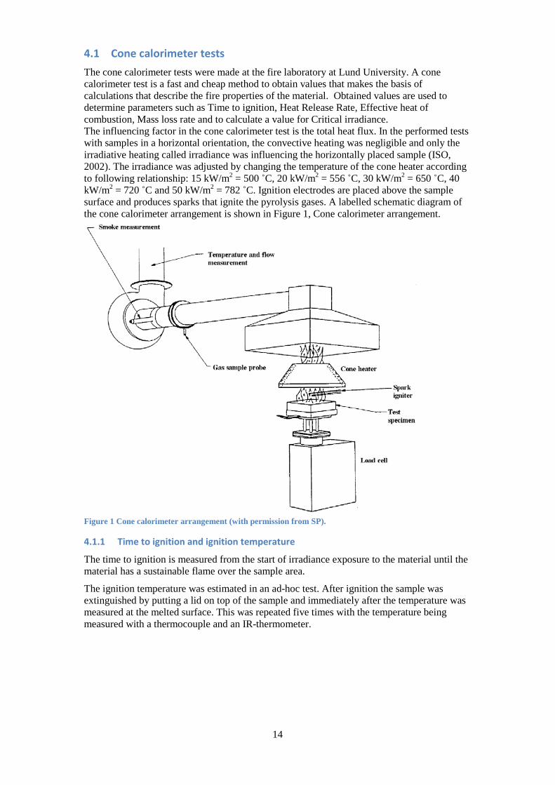
4.1 Cone calorimeter tests The cone calorimeter tests were made at the fire laboratory at Lund University. A cone calorimeter test is a fast and cheap method to obtain values that makes the basis of calculations that describe the fire properties of the material. Obtained values are used to determine parameters such as Time to ignition, Heat Release Rate, Effective heat of combustion, Mass loss rate and to calculate a value for Critical irradiance. The influencing factor in the cone calorimeter test is the total heat flux. In the performed tests with samples in a horizontal orientation, the convective heating was negligible and only the irradiative heating called irradiance was influencing the horizontally placed sample (ISO, 2002). The irradiance was adjusted by changing the temperature of the cone heater according to following relationship: 15 kW/m2 = 500 ˚C, 20 kW/m2 = 556 ˚C, 30 kW/m2 = 650 ˚C, 40 kW/m2 = 720 ˚C and 50 kW/m2 = 782 ˚C. Ignition electrodes are placed above the sample surface and produces sparks that ignite the pyrolysis gases. A labelled schematic diagram of the cone calorimeter arrangement is shown in Figure 1, Cone calorimeter arrangement.
Figure 1 Cone calorimeter arrangement (with permission from SP).
4.1.1 Time to ignition and ignition temperature
The time to ignition is measured from the start of irradiance exposure to the material until the material has a sustainable flame over the sample area.
The ignition temperature was estimated in an ad-hoc test. After ignition the sample was extinguished by putting a lid on top of the sample and immediately after the temperature was measured at the melted surface. This was repeated five times with the temperature being measured with a thermocouple and an IR-thermometer.

15
4.1.2 Heat Release Rate
The heat release rate (HRR) was determined by measuring the difference in oxygen content between the ambient air and in the fire gases, based on the assumption that the energy released by complete combustion per unit oxygen is constant, 13.1 MJ/kg (Janssens, 1991).
The HRR is based on the formula, �̇� = 𝐸 �𝑋𝑂2𝐴0−𝑋𝑂2
𝐴
1−𝑋𝑂2𝐴 � �̇�𝑎
𝑀𝑂2𝑀𝑎
�1 − 𝑋𝐻2𝑂0 − 𝑋𝐶𝑂20 �(Equation 1)
Where: �̇� = Heat release rate [kW] E = Heat released per unit mass of consumed O2 (13,1MJ·kg-1 of O2) Ma = Molecular weight of the incoming air [kg·kmol-1] �̇�𝑎 = Mass flow rate of the incoming air [kg·s-1] 𝑋𝐻2𝑂0 = Mole fraction of H20 in the incoming air 𝑋𝐶𝑂20 = Mole fraction of CO2 in the incoming air
The developed HRR was then divided by sample area to achieve the HRR as kW/m2.
4.1.3 Effective heat of combustion
The oxygen concentration was measured in time sequences about every second and thus by multiplying the calculated heat release rate with the time gap between each measure point, the effective developed energy could be determined (total heat release rate). Dividing the developed energy by the materials mass loss, gives a value for the effective heat of combustion. Any spill during the test is deducted in the mass loss. The unit of the effective heat of combustion is in kJ/g.
4.1.4 Mass Loss Rate
A load cell recorded the mass of the material at every time sequence during the combustion process. The mass loss rate is calculated by the International Standard ISO 5660 (ISO, 2002) described in Manual Cone Calorimeter 2013 (Lund University, 2013). The units for this measurement are grams per second, g/s.

16
4.1.5 Critical irradiance
With knowledge of the time to ignition at various irradiance rates a theoretical critical irradiance, �̇�𝑐𝑟" , can be determined. Janssens (Janssens, 2013) plots the inverse of time to ignition at the power of 0,55, (1/tig)^0,55, against the irradiance of the specific test on the horizontal axis. By extension of the linear best-fit line, the critical irradiance could be determined as where the line crosses the horizontal axis. This is shown in Figure 2. The correlation of the linear best fit is presented as an R2-value. Time to ignition was defined as being from the start of heating until a durable flame was achieved over the sample area.
Figure 2 Determination of Critical irradiance.
The thermal inertia, kρc, was determined according to Hopkins (Donald Hopkins, 1995)
𝑘𝜌𝑐 = 32∙ � 𝜀𝑆𝑙𝑜𝑝𝑒∙(𝑇𝑖𝑔−𝑇0)
�2 (Equation 2)
where: ε is emissivity of flame = 1 Slope slope of the best fit linear trend line to determine �̇�𝑐𝑟" Tig is measured ignition temperature T0 is ambient temperature = 22 °C
4.2 Conetools The output data from the cone calorimeter tests were fed into the software tool Conetools (SP_3, 2002) developed by SP Sveriges Tekniska Forskningsinstitut. Conetools is developed to use the values obtained in small-scale cone calorimeter tests to predict parameters for medium scale fires, by Single Burning Item tests SBI, and full scale fires, by Room Corner Test RCT. The materials should by preference be tested at an irradiance of 50 kW/m2 but values obtained at lower irradiance are also presented as an additional sensitivity analysis. These tests are used for determining parameters for classification according to European fire classification of materials, construction products and building elements. SP delivered Conetools as a 30 –day demo version that was used during the later part of this work, when writing the thesis.
y = 0.0029x - 0.0361 R² = 0.9649
00.020.040.060.08
0.10.120.14
0 10 20 30 40 50 60
(1/t
ig)0,
55 [s
-0,5
5 ]
Irradiance [kW/m2]
Analysis of ignition data
Critical irradiance, determined by information from cone calorimeter tests.
17
4.2.1 European fire classification of materials, construction products and building elements
This European classification system classifies the materials in Euroclasses according to their reaction to fire performance and if the application is a wall and ceiling lining or flooring. Each application system is then divided into seven main classes. Conetools predicts parameters at SBI tests that are used to classify wall and ceiling linings (SP, 2013). For wall and ceiling linings there are seven main classes: A1, A2, B, C, D, E and F where A1 and A2 are seen as limited combustible, B will not go to flashover in a Room Corner Test, C - E are seen as products that can go to flashover in Room Corner Tests and F is considered as a non-tested product (SP_3, 2002). Euroclass A2 - D are also divided into additional classes depending on smoke production and any occurrence of burning droplets.
4.2.2 Single Burning Item
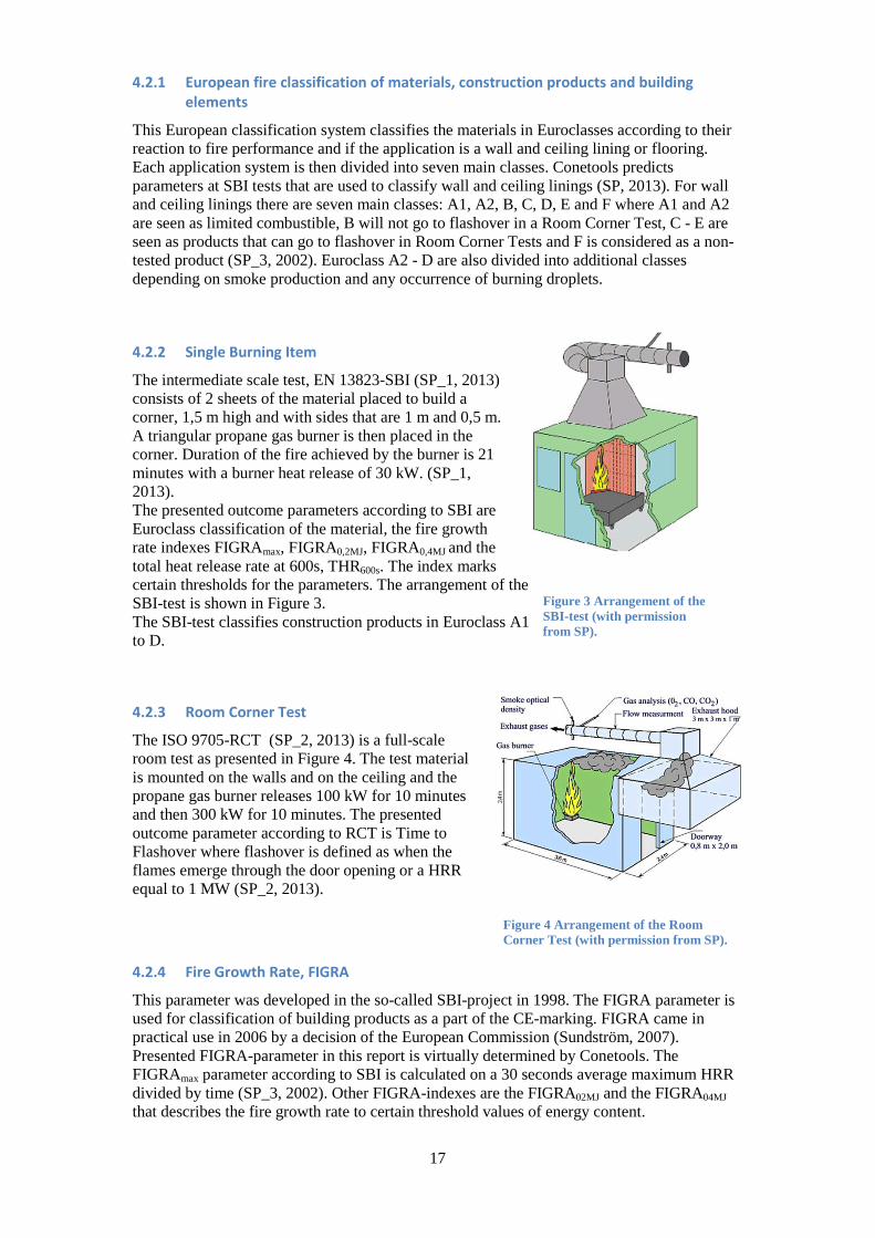
The intermediate scale test, EN 13823-SBI (SP_1, 2013) consists of 2 sheets of the material placed to build a corner, 1,5 m high and with sides that are 1 m and 0,5 m. A triangular propane gas burner is then placed in the corner. Duration of the fire achieved by the burner is 21 minutes with a burner heat release of 30 kW. (SP_1, 2013). The presented outcome parameters according to SBI are Euroclass classification of the material, the fire growth rate indexes FIGRAmax, FIGRA0,2MJ, FIGRA0,4MJ and the total heat release rate at 600s, THR600s. The index marks certain thresholds for the parameters. The arrangement of the SBI-test is shown in Figure 3. The SBI-test classifies construction products in Euroclass A1 to D.
4.2.3 Room Corner Test
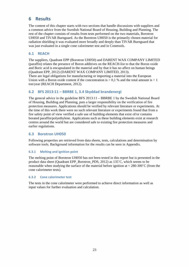
The ISO 9705-RCT (SP_2, 2013) is a full-scale room test as presented in Figure 4. The test material is mounted on the walls and on the ceiling and the propane gas burner releases 100 kW for 10 minutes and then 300 kW for 10 minutes. The presented outcome parameter according to RCT is Time to Flashover where flashover is defined as when the flames emerge through the door opening or a HRR equal to 1 MW (SP_2, 2013).
Figure 4 Arrangement of the Room Corner Test (with permission from SP).
4.2.4 Fire Growth Rate, FIGRA
This parameter was developed in the so-called SBI-project in 1998. The FIGRA parameter is used for classification of building products as a part of the CE-marking. FIGRA came in practical use in 2006 by a decision of the European Commission (Sundström, 2007). Presented FIGRA-parameter in this report is virtually determined by Conetools. The FIGRAmax parameter according to SBI is calculated on a 30 seconds average maximum HRR divided by time (SP_3, 2002). Other FIGRA-indexes are the FIGRA02MJ and the FIGRA04MJ that describes the fire growth rate to certain threshold values of energy content.
Figure 3 Arrangement of the SBI-test (with permission from SP).

18
4.3 Parallel panel tests The Parallel Panel test is a quite conservative test to determine fire properties that depends on a high heat flux. The origin test is a standardised test by FMGlobal (FM Global, 2013). The material plates are mounted in a parallel orientation on a rig with a sand burner placed between the plates according to Figure 5.
Figure 5 Arrangement of the parallel panel test.
Material plates
Sand burner

19
The test differed slightly from the original test from FM Global, instead of having sample dimensions of 2,4 x 0,6 meter, the samples of Borotron UH050 had dimensions of 1,3 x 0,68. Accordingly was the angle iron frame constructed as shown in drawing Ex 2 – A3 in Appendix D. The construction drawing of the sand burner is shown in drawing Ex 3 – A4, Appendix D. In the original test by FM Global, it is specially stated that the materials lower edge should be in contact with the sand burners top to be sure that the distance between the test samples are 305 mm ± 6 mm. This was not possible during the actual test due to the assumed dripping of the material that would affect the sand burner as the melted material would get clogged in the cat litter. Instead the distance between the material and the sand burner was as it is presented in Figure 6.
Figure 6 Distances between sand burner and the material plates.
Preparations besides the mechanical installation as in Figure 5 consisted of adjusting the ventilation to 2 m3/s and checking the functions of the thermocouples in the fire lab and exhaust ventilation system. By putting a lit tealight on top of the cat litter before opening the propane gas flow, the sand burner was lit. When everything else was prepared such as the video camera, light and extinguish arrangement, the propane gas tank was opened and the propane gas flow was adjusted to 40 normal litres per minute, [Nl/min]. This flow releases approximately 60 kW of heat as it is lit. The heat release from the sand burner is as stated in the origin FM Global test and releases heat that can be compared to a burning waste basket. The propane flow at the sand burner was lit just after opening the propane gas tank. The initial intention was to let the sand burner be lit for 10 minutes according to the original FM Global test (FM Global, 2013) but the fire got too big so the gas was shut off at 4 minutes and 50 seconds after the time of opening the gas flow. The fire had to be extinguished by the internal water sprinkler system.

20
4.4 Smoke potential The smoke potential was obtained by combusting samples, 98x98x30 mm, of Borotron UH050 under an exhaust hood and measuring the optical density in the exhaust gases. The test was repeated 3 times with 2-3 samples at each test. The burning material and the exhaust system is presented in Figure 7. The bulb and photocell for measuring visibility is placed in the far end of the horizontal exhaust duct.
To achieve the smoke potential, Sp, following relationship was used (Lunds Tekniska Högskola, n.d.):
𝑆𝑝 = 𝐷𝑒∙�̇�298Δ−𝑤𝑒𝑖𝑔ℎ𝑡
[Obscuram3/g] (Equation 3)
where:
De optical density per length unit [dB/m = Obscura] �̇�298 gas flow in the ventilation duct at 25°C (298 K) and 1 atm [m3] Δ-weight combusted material at the measurement of De and �̇�298
The expression, 𝐷𝑒 ∙ �̇�298, was calculated as the sum of the integrated value at each time sequence. The optical density (De) was calculated as
𝐷𝑒 = 10𝐿∙ log �𝐼0
𝐼� [dB/m] (Equation 4)
where:
L length of the light stream (length between bulb and photocell) [m] I0 light intensity, without fire gases, received at the photocell I light intensity, with fire gases, received at the photocell
L was measured before the tests, I0 was measured before igniting the material and I was measured during the tests. Besides the optical density, the volume flow was determined by using the formula:
�̇�298 = 22,4 ∙ 𝐴 ∙ 𝐾𝑡𝐾𝑝∙ �Δ𝑃
𝑇𝑠 (Equation 5)
where:
Kt is a correction factor determined to 0,9 due to obtain an average flow Kp is a factor determined to 1,08 due to correct measurement error caused at the actual
Reynolds number ΔP dynamic pressure obtained in the centre of the ventilation duct [Pa] Ts temperature of the fire gases [K] All tests were divided into time sequences about one second.
Figure 7 Burning material under the exhaust hood.

21
5 Material and equipment
5.1 Materials Borotron UH050 Borotron UH050 is a polyethylene-based material with a Boron additive of Boron oxide. The material is especially developed for use in applications where neutron shielding is needed. Dimensions: 98x98x30 mm for the Cone calorimeter tests
1330x680x30 mm for the Parallel panel test 98x98x30 mm to determine Smoke potential
UH in Borotron UH050 stands for Ultra High molecular weight Density: 1.005 g/cm3 The Boron oxide additive is 16,0%1, which results in a Boron content of 5%. Purchased at Carlsson & Möller in Helsingborg, Sweden Purchase document can be found in Appendix E
TIVAR Burnguard TIVAR Burnguard is a polyethylene-based material with a non-halogenated additive that provides the material with flame retardant properties. TIVAR Burnguard is approved to meet the requirements of UL 94 V-0 as of 6 mm thickness. It is also stated to be self-extinguishing (Quadrant, 2011). Dimensions: 70x90x8 for the single Cone calorimeter test Carlsson & Möller delivered TIVAR Burnguard as a test sample.
1 Boron oxide, B2O3, has a molecule weight = 2x10,81+3x16,00 = 69,62 u. Proportion of Boron in Boron oxide = 2x10,81/69,62 = 0,3105 Density of Borotron UH050 = 1,005 g/cm3 Weight % of Boron in Borotron UH050 = (0,3105 x XBoron oxide x 1,005) x 100 = 5 % so Weight %, XBoron oxide, of Boron oxide is = 0,05/(0,3105x1,005)x100 = 16,02 %

22
5.2 Equipment Cone calorimeter tests The cone calorimeter at the fire laboratory at Lund University, was delivered by Fire Testing Technology Serial number: 3022511 The experiments are based on the description given in ISO 5660-1 (ISO, 2002). Filter masses: Silica gel and glass fibre Nitrogen gas Sample holder Aluminium foil Aluminium tape Ceramic wool IR Thermometer PC with software IMPLOG 2000
Parallel panel test The test was made at the fire laboratory at MSB in Revinge. Limited heat release: 1MW Sand burner, 0,6x0,3x0,3 m Cat litter for the sand burner Bottle of Propane with regulator, flow meter and hose, 11kg Support to hold material Plywood, 4 pcs 1200x620x12 mm Medium Fibre Board, 4 pcs 1200x620x12 mm Calcium Silicate Insulation board, 2 pcs 1200x600x12 mm Aluminium foil Plasterboard, 2 pcs 2400x900x12 mm
Smoke potential test The test was made at the fire laboratory at Lund University. Limited heat release: 100 kW Bidirectional probe for pressure measurement Steel tray 2 bricks Aluminium foil Light bulb and photocell to measure visibility PC with software IMPLOG 2000 Temperature probe Scale delivered by Mettler Toledo Small piece of mineral wool
Conetools Version 2.3.0 SP Fire Technology 2004. DEMO-version
23
6 Results The content of this chapter starts with two sections that handle discussions with suppliers and a common advice from the Swedish National Board of Housing, Building and Planning. The rest of the chapter consists of results from tests performed on the two materials, Borotron UH050 and TIVAR Burnguard. As the Borotron UH050 is the primarily chosen material for radiation shielding it was evaluated more broadly and deeply than TIVAR Burnguard that was just evaluated in a single cone calorimeter test and in Conetools.
6.1 REACH The suppliers, Quadrant EPP (Borotron UH050) and DARENT WAX COMPANY LIMITED (paraffin) relates the presence of Boron additives on the REACH-list to that the Boron oxide and Boric acid is encapsulated in the material and by that it has no affect on human beings (Quadrant EPP, 2012) (DARENT WAX COMPANY LIMITED, 2013). There are legal obligations for manufacturing or importing a material into the European Union with a Boron oxide content if the concentration is > 0,1 % and the total amount is > 1 ton/year (REACH Department, 2012).
6.2 BFS 2013:11 – BBRBE 1, 3.4 Skyddad brandenergi The general advice in the guideline BFS 2013:11 – BBRBE 1 by the Swedish National Board of Housing, Building and Planning, puts a larger responsibility on the verification of fire protection measures. Applications should be verified by relevant literature or experiments. At the time of this work there were no such relevant literature or experiments found that from a fire safety point of view verified a safe use of building elements that exist of/or contains borated paraffin/polyethylene. Applications such as these building elements exist at research centres around the world but are considered safe to existing fire protection measures and earlier regulations.
6.3 Borotron UH050 Following properties are retrieved from data sheets, tests, calculations and determination by software tools. Background information for the results can be seen in Appendix.
6.3.1 Melting and ignition point
The melting point of Borotron UH050 has not been tested in this report but is presented in the product data sheet (Quadrant EPP_Borotron_PDS, 2012) as 135˚C, which seems to be reasonable when studying the surface of the material before ignition at ≈ 280-300˚C (from the cone calorimeter tests).
6.3.2 Cone calorimeter test
The tests in the cone calorimeter were performed to achieve direct information as well as input values for further evaluation and calculation.
24
6.3.2.1 Self extinguish test
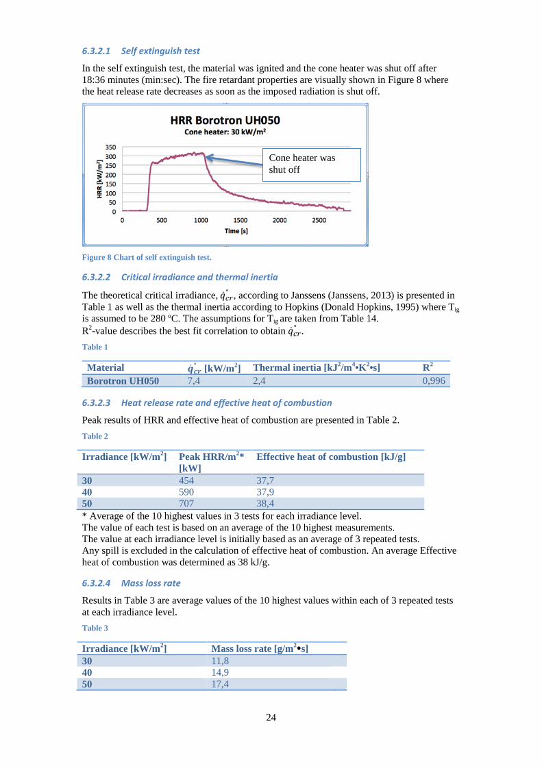
In the self extinguish test, the material was ignited and the cone heater was shut off after 18:36 minutes (min:sec). The fire retardant properties are visually shown in Figure 8 where the heat release rate decreases as soon as the imposed radiation is shut off.
Figure 8 Chart of self extinguish test.
6.3.2.2 Critical irradiance and thermal inertia
The theoretical critical irradiance, �̇�𝑐𝑟" , according to Janssens (Janssens, 2013) is presented in Table 1 as well as the thermal inertia according to Hopkins (Donald Hopkins, 1995) where Tig is assumed to be 280 ºC. The assumptions for Tig are taken from Table 14. R2-value describes the best fit correlation to obtain �̇�𝑐𝑟" . Table 1
Material �̇�𝒄𝒓" [kW/m2] Thermal inertia [kJ2/m4•K2•s] R2 Borotron UH050 7,4 2,4 0,996
6.3.2.3 Heat release rate and effective heat of combustion
Peak results of HRR and effective heat of combustion are presented in Table 2. Table 2
Irradiance [kW/m2] Peak HRR/m2* [kW]
Effective heat of combustion [kJ/g]
30 454 37,7 40 590 37,9 50 707 38,4 * Average of the 10 highest values in 3 tests for each irradiance level. The value of each test is based on an average of the 10 highest measurements. The value at each irradiance level is initially based as an average of 3 repeated tests. Any spill is excluded in the calculation of effective heat of combustion. An average Effective heat of combustion was determined as 38 kJ/g.
6.3.2.4 Mass loss rate
Results in Table 3 are average values of the 10 highest values within each of 3 repeated tests at each irradiance level. Table 3
Irradiance [kW/m2] Mass loss rate [g/m2s] 30 11,8 40 14,9 50 17,4
Cone heater was shut off

25
6.3.2.5 Residue examination
After the Borotron UH050 had been combusted there was a colourless glass-like residue left with some tar in the aluminium foil wrapping. The residue is presented in Figure 9.
Figure 9 Colourless glass-like residue after combusting Borotron UH050.
The average weight of the residue could be determined to 50,6 g. By dividing the residue weight by the sample weight of 298 g the average residue part was determined to17 %. It is likely to believe that the residue contains the Boron oxide additive as the supplier stated its content to be 16 %, Appendix E.
6.3.3 Conetools
Obtained values from cone calorimeter tests were imported into Conetools to determine parameters as FIGRA, Total Heat Release, Euroclass and Time to Flashover. According to the Conetools manual (SP_3, 2002) the values obtained at an irradiance of 50 kW/m2 should be used as design values by preference. As we had more data each level was used as input which is according the software also possible as the programme has a procedure to adapt results from other irradiance levels.
6.3.3.1 FIGRA by SBI
The FIGRA parameters are presented in Table 4 as calculated max-values in total and at energy thresholds at 0,2MJ and 0,4 MJ. The value at each irradiance level is initially based as an average of 3 repeated tests. Table 4
Irradiance [kW/m2]
FIGRAmax [W/s]
FIGRA02max [W/s]
FIGRA04max [W/s]
30 203,5 203,5 203,5 40 355,5 355,5 355,5 50 470,9 470,9 470,9
26
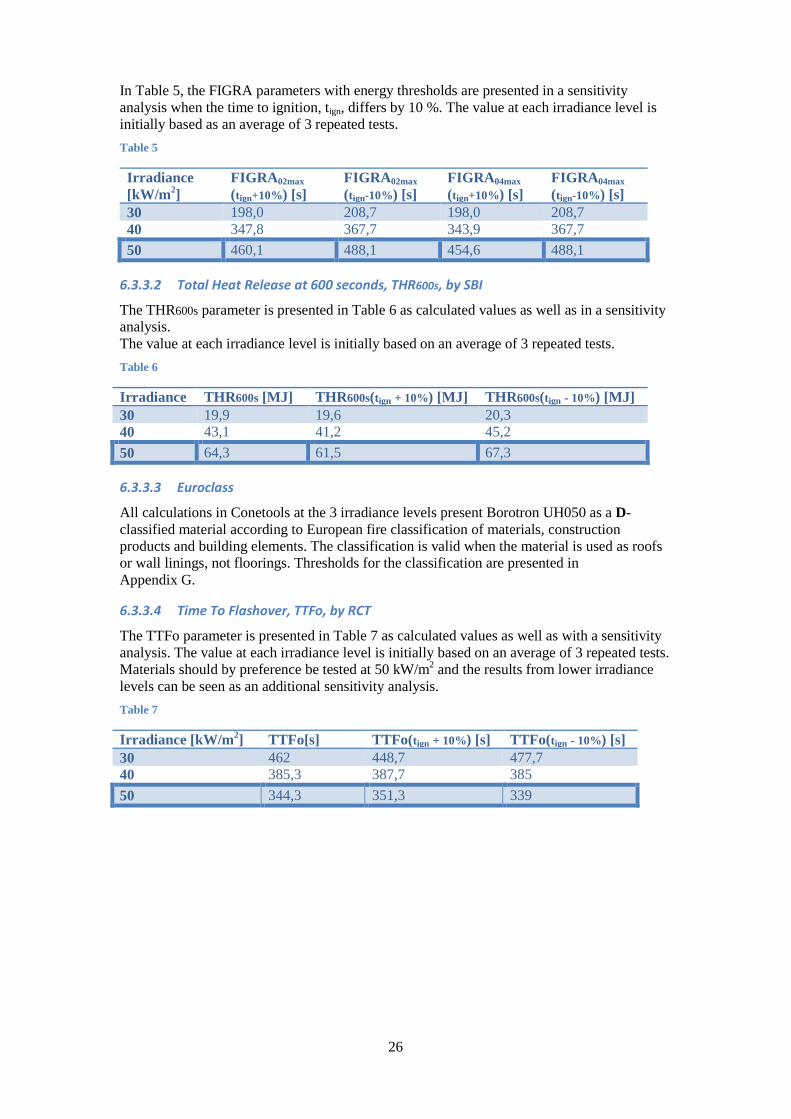
In Table 5, the FIGRA parameters with energy thresholds are presented in a sensitivity analysis when the time to ignition, tign, differs by 10 %. The value at each irradiance level is initially based as an average of 3 repeated tests. Table 5
Irradiance [kW/m2]
FIGRA02max (tign+10%) [s]
FIGRA02max (tign-10%) [s]
FIGRA04max (tign+10%) [s]
FIGRA04max (tign-10%) [s]
30 198,0 208,7 198,0 208,7 40 347,8 367,7 343,9 367,7 50 460,1 488,1 454,6 488,1
6.3.3.2 Total Heat Release at 600 seconds, THR600s, by SBI
The THR600s parameter is presented in Table 6 as calculated values as well as in a sensitivity analysis. The value at each irradiance level is initially based on an average of 3 repeated tests. Table 6
Irradiance THR600s [MJ] THR600s(tign + 10%) [MJ] THR600s(tign - 10%) [MJ] 30 19,9 19,6 20,3 40 43,1 41,2 45,2 50 64,3 61,5 67,3
6.3.3.3 Euroclass
All calculations in Conetools at the 3 irradiance levels present Borotron UH050 as a D-classified material according to European fire classification of materials, construction products and building elements. The classification is valid when the material is used as roofs or wall linings, not floorings. Thresholds for the classification are presented in Appendix G.
6.3.3.4 Time To Flashover, TTFo, by RCT
The TTFo parameter is presented in Table 7 as calculated values as well as with a sensitivity analysis. The value at each irradiance level is initially based on an average of 3 repeated tests. Materials should by preference be tested at 50 kW/m2 and the results from lower irradiance levels can be seen as an additional sensitivity analysis. Table 7
Irradiance [kW/m2] TTFo[s] TTFo(tign + 10%) [s] TTFo(tign - 10%) [s] 30 462 448,7 477,7 40 385,3 387,7 385 50 344,3 351,3 339

27
6.3.4 Parallel Panel test
From the parallel panel test in Revinge, quantitative and qualitative results were obtained. When the sand burner was lit it showed that the ventilation caused the flame to bend over nearer to the left sample sheet and after a small adjustment of lowered ventilation flow the flame went more upright but still as shown in Figure 10.
Figure 10 The sand burner is lit.
After 2:10 (minutes:seconds), the left material plate started dripping melted material that was burning and 5 seconds later the lower part of the material plate was ignited, see Figure 11. The left material plate had major dripping after 2:30.
Figure 11 The left material plate is ignited and burning material drops on the floor.

28
After 4 minutes the right sample sheet started to burn as seen in Figure 12.
Figure 12 Both material plates are burning.
The fire propagation was quite high and as the maximum heat release at the fire lab is 1 MW the propane flow was shut off after 4.50. In Figure 13 it is shown that the sand burner is not delivering any heat to the fire after the propane gas flow is shut off.
Figure 13 Propane gas flow is shut off (no flames at the sand burners top).
29
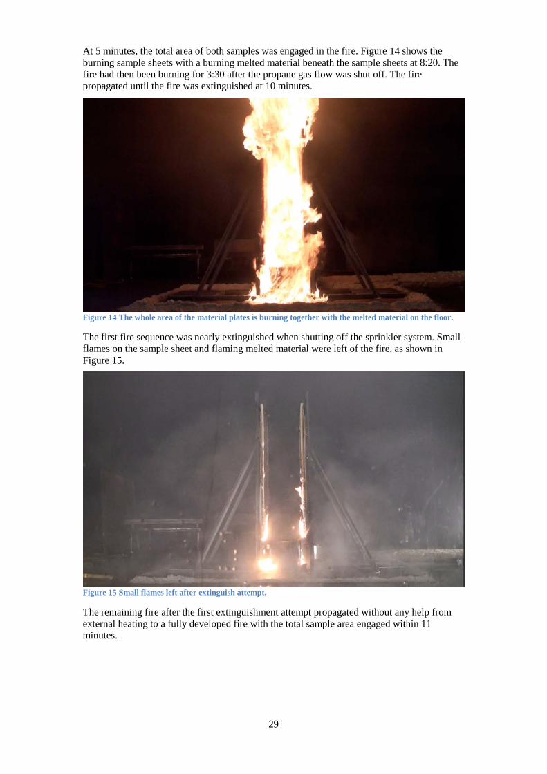
At 5 minutes, the total area of both samples was engaged in the fire. Figure 14 shows the burning sample sheets with a burning melted material beneath the sample sheets at 8:20. The fire had then been burning for 3:30 after the propane gas flow was shut off. The fire propagated until the fire was extinguished at 10 minutes.
Figure 14 The whole area of the material plates is burning together with the melted material on the floor.
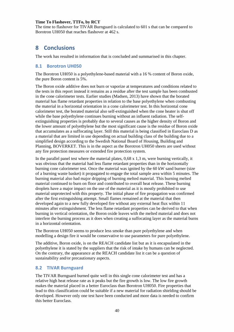
The first fire sequence was nearly extinguished when shutting off the sprinkler system. Small flames on the sample sheet and flaming melted material were left of the fire, as shown in Figure 15.
Figure 15 Small flames left after extinguish attempt.
The remaining fire after the first extinguishment attempt propagated without any help from external heating to a fully developed fire with the total sample area engaged within 11 minutes.

30
Whole area of the 2 sample plates is burning again as shown in Figure 16.
After the last extinguishment of the fire with the water sprinkler system it can be seen in Figure 17 that the lower parts of the material plates are heavily damaged by heat and fire. Below the material plates, the melted material has piled up. The melted material contained a lot of hard granular residues likely to be boron oxide. Notable is that the melted material did not cause a pool fire but seemed to be solidified as it got in contact with the gypsum plasterboard.
Figure 17 The melted material is piled up beneath the material plates.
Figure 16 Both sample areas are engaged in the fire.

31
6.3.5 Smoke potential
Table 8 presents the results of the tests made to determine the smoke potential. The conditions during the tests were that material was burning with flames at a mass loss rate of 1-4 g/10s. Table 8
Test Smoke potential [Obscuram3/g] 1 0,40 2 0,21 3 0,52
6.4 TIVAR Burnguard Carlsson & Möller delivered this material after discussions about fire retardant polyethylene-based materials. The purpose was to make a single test to get a sense of the fire retardant properties if a new Boron-loaded shielding material should be based on the TIVAR Burnguard material.
6.4.1 Cone calorimeter test
The TIVAR Burnguard material was only tested in a single cone calorimeter test at the irradiance of 30 kW/m2. A thermocouple was mounted in order to measure the ignition point but as soon as the material was exposed to the heating from the cone it started to expand and the attached thermocouple loosened from the surface. When working with the loosened thermocouple the material ignited but by studying the heat release rate curve the ignition point can be determined at 220 seconds. The expansion of the material was large during the heating and burning process. The material grew approximately 15 times the original thickness. The material starts expanding and releases granular-sized particles as it gets exposed to heat. After a while, the top of the expanding material surface comes closer to the cone heater, the incident irradiance becomes higher and the material ignites and burns with a well-defined flame. In Figure 18, the original size and shape are compared to the material residues from the test. The material residues had a larger top that was removed in order to get the material out of the cone calorimeter.
Figure 18 Comparison between the original size and the residues after combustion.

32
In Figure 19, the burning process is visualized and as shown it burns with a well-defined flame.
Figure 19 TIVAR Burnguard burning with a well-defined flame.

33
The material was totally combusted besides the granular-sized residues. The original material and the residues can be seen in Figure 20.
Figure 20 The original material and the residues.
6.4.1.1 Heat Release Rate
The Heat Release Rate peaks at around 450 kW/m2.
Figure 21 Chart of the heat release rate.

34
6.4.1.2 Mass loss
The mass loss of the sample is presented in Figure 22. The material was combusted and left a very low density residue of granulates with virtually no measureable mass.
Figure 22 Chart of the mass loss.
6.4.1.3 Mass Loss Rate
The Mass Loss Rate peaked at 8 g/m2·s in the middle of the burning process. The peak values around 200s are most likely due to the fact that the intumescing material got in contact with the heater.
Figure 23 Mass loss rate as a function of time.
6.4.1.4 Heat of Combustion
The total energy of the material was calculated as the heat release rate integrated over time in Figure 21. The total energy was then divided by the total mass loss in Figure 22, which results in the Effective heat of combustion as shown in Table 9. Table 9
Heat of Combustion 39,2 kJ/g

35
6.4.2 Conetools
As written in recent chapters, the obtained values relate to a single test that corresponds to the following parameters obtained by a single calculation in Conetools. Notable is also that by preference the irradiance should be 50 kW/m2. This was not known at the time of the cone calorimeter test. However Conetools has an internal correction procedure as earlier stated but it means that the results might have a larger uncertainty.
6.4.2.1 FIGRA by SBI
The FIGRA parameters are presented in Table 10 as calculated max-values in total and at energy thresholds at 0,2MJ and 0,4 MJ. In Table 11, the FIGRA parameters with energy thresholds are presented in a sensitivity analysis when the time to ignition, tign, differs by 10 %. Table 10
Irradiance [kW/m2] FIGRAmax [W/s] FIGRA02max [W/s] FIGRA04max [W/s] 30 71,4 71,4 71,4
Table 11
Irradiance [kW/m2]
FIGRA02max (tign+10%) [W/s]
FIGRA02max (tign-10%) [W/s]
FIGRA04max (tign+10%) [W/s]
FIGRA04max (tign-10%) [W/s]
30 71,4 73,4 71,4 73,4
6.4.2.2 Total Heat Release at 600 seconds, THR600s, by SBI
The THR600s parameter is presented in Table 12 as calculated values and with a sensitivity analysis. Table 12
Irradiance THR600s [MJ] THR600s(tign + 10%) [MJ] THR600s(tign - 10%) [MJ] 30 6,6 6,4 6,8
6.4.2.3 Euroclass
The single calculation in Conetools present TIVAR Burnguard as a A2/B-classified material according to European fire classification of materials, construction products and building elements. However, note that the irradiance by preference should be 50 kW/m2 instead of the performed 30 kW/ m2 test. This was not known at the time of the single cone calorimeter test. However Conetools has an internal correction procedure as earlier stated but it means that the results might have a larger uncertainty.
6.4.2.4 Time To Flashover, TTFo, by RCT
The TTFo parameter is presented in Table 13 as a calculated value along with a sensitivity analysis. Table 13
Irradiance [kW/m2] TTFo[s] TTFo(tign + 10%) [s] TTFo(tign - 10%) [s] 30 601 601 608

36
7 Discussion and analysis The results are discussed, analysed and sometimes compared to other common used building materials such as Oriented Strand Board, OSB (EPF, 2013), and untreated timber (Lowden & Hull, 2013).
7.1 Methods There are a lot of test methods that could be applicable in testing fire properties for radiation shielding. The used methods are chosen by the following motivations: Cone calorimeter tests are cheap and cost effective and the laboratory equipment was possible to use without charge. The cone calorimeter tests together with Conetools gives a virtual determined value of the Euroclass parameter. Cone Calorimeter tests have proven to give good prediction of real scale behaviour (SP_3, 2002). The Parallel panel test was chosen as it gives a conservative but still relevant qualitative assessment of the materials behaviour when it is exposed to heat and fire. It is also used by one of the major insurance companies where the link to real scale tests has been demonstrated (FM Global, 2013). The determination of Smoke potential was made as an ad-hoc test to get a sense if the Boron oxide has an impact on the smoke potential related to the base polyethylene.
7.1.1 Cone calorimeter test
The equipment was adjusted with daily calibrations according to the manual. Results can differ if the material is not homogeneously mixed. Time to ignition is quite dependent on the conditions close to the ignition electrodes. Material composition and concentration of pyrolysis gases affect the ability to achieve ignition.
7.1.2 Conetools
Conetools is a software tool that transfers obtained values from cone calorimeter test to predict virtual values of SBI-tests and RCT. Research of the accuracy shows that the results are satisfactory (SP_3, 2002, p.2). Some caution is stated when it is used for materials which have a lot of mechanical behaviour or melting. In this case it is important to run also real SBI or room corner tests but this was out of the scope of this project. By preference the tests should be done at irradiance 50 kW/m2. Results are also presented at irradiance 30 and 40 kW/m2 since as an additional sensitivity analysis to verify that even with a lower fire growth rate the material has the same Euroclass as for the 50 kW/m2. This was the case when classifying according to Euroclasses for Borotron UH050. The TIVAR Burnguard was tested at 30 kW/m2 as the most optimal choice. For Conetools the internal adjustment procedure could take care of the fact that the material was not tested at 50 kW/m2.
7.1.3 Parallel Panel test
The developed heat from the sand burner and burning material exposes the material for a heat flux at a high rate and a real flame. This increases the fire growth rate and the whole burning process and reflect more the real fire behaviour. Applications as this cannot be seen as the most likely scenarios but it should be seen as a conservative approach to actual conditions when investigating the fire properties.
7.1.4 Smoke potential test
The three tests were made as ad-hoc tests to relate the obtained values to a reference value of pure polyethylene by Tewarson (Tewarson, 1979). Tewarsons test method is described as combustion of a horizontal fuel surface with a diameter of 10 cm. The combustion gases were diluted by an airflow of 35 l/s and collected in a duct of 6 cm diameter where the visibility was measured. The Tewarson test was made under ”Flaming combustion”. The made tests in this work were also made under flaming combustion but at a larger dilution of the combustion gases. The airflow in duct was 240 l/s and the visibility was measured in a duct with a diameter of 200 cm. This may have an affect

37
if the used equipment varies at different measuring lengths and visibility due to dilution of the combustion gases. But in both methods the visibility is calculated in regard of the actual airflow and measuring length of the light beam and photocell.
7.2 Results The obtained results from the test, calculations and quantitative assessments showed similarity between the repeated tests and resulted in reasonable repeatable values.
7.2.1 Borotron UH050
The Borotron UH050 material was the most evaluated material. Each cone calorimeter test was repeated 3 times and an average value was used as direct output or input to other calculations.
7.2.1.1 Cone calorimeter test
Self extinguish test The result was the same as for previous tests on borated polyethylene with a 3 % Boron oxide content (Madsen, 2013). Reliability of this result stands on strong basis under the circumstance that the material is combusted in a horizontal orientation in an aluminium foil tray.
Critical irradiance The calculated value of critical irradiance of 7,4 kW/m2 seems to be quite low. Reference literature as SFPE handbook of fire protection engineering (SFPE, 2002, p.621) present 15 kW/m2 as a critical irradiance for high-density polyethylene. Critical irradiance differs between different thicknesses of the same the material and due to the backing material that is used below the tested material. Janssen (Janssens, 2013) mentions in his report that values of time to ignition obtained at low irradiances in cone calorimeter tests differ between different thicknesses. This will affect the outcome of the critical irradiance and the easiest way to avoid this is to exclude values obtained at low irradiance. This would raise the critical irradiance of Borotron UH050 closer to 10 kW/m2. Different qualities and densities of polyethylene may also contribute to the result. However the value is considered as being rather low.
Heat release rate The developed heat release rate at the cone calorimeter tests is quite similar at each irradiance level. The heat release rate increases at the end of the test. This is likely due to that the developed heat stays at the melted material in the surface instead of conducting to the remaining non-melted material. When comparing the Borotron UH050 to base polyethylene as shown in the SFPE Handbook in fire protection engineering (SFPE, 2002, p.134) the high-density polyethylene has peak heat release rate values at 1400 kW/m2 for 6 mm samples at an irradiance of 40kW/m2. This is a significant difference in heat release rate between the materials as the heat release rate for Borotron UH050, at irradiance 40 kW/m2, is approximately 400 kW/m2 with peaks at 700 kW/m2 at the end of the burning process. Similar experiences was also determined in report Fire properties of borated paraffin and borated polyethylene (Madsen, 2013) where both base polyethylene as well borated polyethylene was examined in cone calorimeter tests. Some reduction is hence observed but the values are still rather high.
Mass Loss Rate
The mass loss rate increases by the irradiance level and peaks at 17,4 g/m2s, 50 kW/m2. By studying the charts in Appendix A it can be seen that the mass loss rate at 50 kW/m2 is quite steady at 10 g/m2s in the first part of the burning process. At the end of the test it increases as the material gets melted and the developed heat stays in the surface layer instead of being conducted to the solid phase of the material.

38
Residue evaluation
It is likely to define the residue as the Boron oxide additive. An earlier study by Madsen (Madsen, 2013) shows that base polyethylene does not leave any residue after the material has been combusted. The appearance of the residue also fits the physical properties of Boron oxide as described by Australian NPI (Australian Goverment, n.d.) as a semi-transparent material that usually forms a glass.
7.2.1.2 Conetools
Conetools calculates input data from cone calorimeter tests to predict parameters at SBI test and RCT. A general warning should be made here due to the fact that the material has a melting behaviour that affects the properties.
FIGRA The FIGRA-parameter is one of the values that classify the material to a certain Euroclass. The virtual FIGRA-value at irradiance of 50 kW/m2 was determined to an average of 471 W/s. That leads to that the material is placed in the middle of D-classification that has thresholds values of > 250 W/s and ≤ 750 W/s. The sensitivity analysis of the FIGRA-parameter shows that by changing time to ignition ± 10 % does not really affect the fire growth. Nor do the energy thresholds values affect the determined fire growth. Also the other FIGRA-values obtained at 30- and 40 kW/m2 places the material in Euroclass D, which confirms the actual Euroclassification.
Time To Flashover
The time to flashover in the RCT is determined to 344 s. Reference values for OSB (USDA, 2012), 11mm thickness, is 189 s. Here it should be noted that the thickness of the Borotron UH050 was 30mm. A thinner material sample of Borotron UH050 should give a shorter time to flashover.
Total Heat Release
The determined total heat release at 600 s was 64 MJ. That can be compared to SBI-test on (USDA, 2012) that reached 82 MJ (Framehomes, 2010) at 600 s.
Euroclass
The D-classification of the Borotron UH050 is based on the FIGRA-parameter that for Borotron UH050 was 471 kW/m2. Additional classes within the D-classification are based on smoke production and burning droplets. However, since the smoke production is not measured and the burning droplets cannot be calculated numerically in Conetools, this additional classification has not been done. It should be noted that by evaluation of the Parallel panel test and the experience of the burning droplets in that test it would most likely appear burning droplets in the SBI-test as well. Other D-classified materials are OSB (EPF, 2013) and untreated timber (Lowden & Hull, 2013).
7.2.1.3 Parallel Panel Test
The result from the parallel panel test was a bit different than expected. It was assumed that the Boron oxide content that formed a suffocating layer in the horizontal cone calorimeter tests would also have an impact now for the vertical placed material. The material ignited quite quickly and the plan was to release heat from the sand burner during 10 minutes but after 4 minutes the fire propagation was so high that it was estimated that the limit for the maximum heat release of 1 MW at the lab was close to being reached. The propane gas flow was shut off after 4:50 but the fire propagation continued and an attempt to extinguish the fire with 2 carbon dioxide fire extinguishers was made but without success. The total area of the sample plates was engaged in the fire at 5 minutes. Finally the fire was heavily suppressed by manual activation of the internal water sprinkler system at the laboratory. Small flames at the lower parts of the material remained after the manual actuation and the fire was let to propagate again without any external influent radiation or extra flame source. Now the

39
material probably was slightly heated but still under the melting temperature of 135°C. Within 11 minutes, the material was burning again over its whole area. This latter fire propagation was made in an ambient airflow with very high moisture content as the sprinkler system had released a lot of water on the material and the floor area. It was an important experience to see the fire propagation without any external heat flux. The material did not visually show any fire retardant properties due to the Boron oxide.
7.2.1.4 Smoke potential
These 3 tests were made to get a sense of the materials smoke potential. The results show that the Borotron UH050 has a lower production of smoke than pure polyethylene that was tested by Tewarson. The obtained values of 0,21-0,4-0,52 Obm3/g were quite low for a polyethylene based material. Tewarson (Tewarson, 1979) present the smoke potential for pure polyethylene to be 1,52 Obm3/g. An outcome of the tests in this report could determine that the smoke potential is at least not worse than for pure polyethylene. Smoke production however depends a lot on the ventilation conditions.
7.2.2 TIVAR Burnguard
The material starts to expand and breaks up at an irradiance of 30 kW/m2. The time to ignition was missed in the single test due to that focus was at a loosened thermocouple but was later estimated from the heat release curve. As soon as the solid surface material started to expand it approached the cone heater and got exposed to a higher irradiance and then it ignited. However it shows that the protective layer is not completely sufficient and mainly extends the ignition time. More work is needed here.
7.2.2.1 Cone calorimeter test
Only a single test was performed at 30 kW/m2. Heat Release Rate The heat release rate has a peak close to the value of Borotron UH050 but the fire growth to the peak is quite slow and as the heat release has peaked, the decay rate is similar as the previous fire growth. Mass Loss The combusted material left a low density residue of granulates in the sample holder. As base polyethylene is being combusted completely, the residue could be the fire retardant additive (char). Mass Loss Rate The mass loss rate has a slow growth but peaks at 8 g/m2·s. Heat of Combustion The energy value of TIVAR Burnguard is a bit lower than base polyethylene but still it has a high-energy content.
7.2.2.2 Conetools
As only a single cone calorimeter test was performed at 30 kW/m2 and that values obtained at 50 kW/m2 should be used as a preference, the results should only be seen as indicative. FIGRA by SBI The fire growth of 71 W/s is low due to fire retardant properties mainly because of the increased ignition time. Total Heat Release at 600 seconds, THR600s, by SBI The released energy, 6,6 MJ, at 10 minutes is low compared to 19,9 MJ for Borotron UH050. Euroclass The classification to Euroclass A2/B is interesting and caused by the low fire growth. The classification provides opportunities for this kind of fire retardant material. But as mentioned earlier the material is only tested in a single cone calorimeter test and at 30 kW/m2 instead of 50 kW/m2 that should be used as preference.
40
Time To Flashover, TTFo, by RCT The time to flashover for TIVAR Burnguard is calculated to 601 s that can be compared to Borotron UH050 that reaches flashover at 462 s.
8 Conclusions The work has resulted in information that is concluded and summarised in this chapter.
8.1 Borotron UH050 The Borotron UH050 is a polyethylene-based material with a 16 % content of Boron oxide, the pure Boron content is 5%.
The Boron oxide additive does not burn or vaporize at temperatures and conditions related to the tests in this report instead it remains as a residue after the test sample has been combusted in the cone calorimeter tests. Earlier studies (Madsen, 2013) have shown that the borated material has flame retardant properties in relation to the base polyethylene when combusting the material in a horizontal orientation in a cone calorimeter test. In this horizontal cone calorimeter test, the borated material also self-extinguished when the cone heater is shut off while the base polyethylene continues burning without an influent radiation. The self-extinguishing properties is probably due to several causes as the higher density of Boron and the lower amount of polyethylene but the most significant cause is the residue of Boron oxide that accumulates as a suffocating layer. Still this material is being classified in Euroclass D as a material that are limited in use depending on actual building class of the building due to a simplified design according to the Swedish National Board of Housing, Building and Planning, BOVERKET. This is in the aspect as the Borotron UH050 sheets are used without any fire protection measures or extended fire protection system.
In the parallel panel test where the material plates, 0,68 x 1,3 m, were burning vertically, it was obvious that the material had less flame retardant properties than in the horizontally burning cone calorimeter test. Once the material was ignited by the 60 kW sand burner (size of a burning waste basket) it propagated to engage the total sample area within 5 minutes. The burning material also had major dripping of burning melted material. This burning melted material continued to burn on floor and contributed to overall heat release. These burning droplets have a major impact on the use of the material as it is mostly prohibited to use material unprotected with this property. The initial phase of fire propagation was confirmed after the first extinguishing attempt. Small flames remained at the material that then developed again to a new fully developed fire without any external heat flux within 11 minutes after extinguishment. The less flame retardant properties can be derived to that when burning in vertical orientation, the Boron oxide leaves with the melted material and does not interfere the burning process as it does when creating a suffocating layer as the material burns in a horizontal orientation.
The Borotron UH050 seems to produce less smoke than pure polyethylene and when modelling a design fire it would be conservative to use parameters for pure polyethylene.
The additive, Boron oxide, is on the REACH candidate list but as it is encapsulated in the polyethylene it is stated by the suppliers that the risk of intake by humans can be neglected. On the contrary, the appearance at the REACH candidate list it can be a question of sustainability and/or precautionary aspects.
8.2 TIVAR Burnguard The TIVAR Burnguard burned quite well in this single cone calorimeter test and has a relative high heat release rate as it peaks but the fire growth is low. The low fire growth makes the material placed in a better Euroclass than Borotron UH050. Fire properties that lead to this classification could be suitable if a new material for radiation shielding should be developed. However only one test have been conducted and more data is needed to confirm this better Euroclass.

41
8.3 Building codes and classification The Euroclass D classification of Borotron UH050 as well as the experienced fire propagation and burning droplets from the parallel panel test makes the material difficult to use without fire protection measures.
8.4 BFS 2013:11 BBRBE 1, 3.4 Skyddad brandenergi The general advice puts a larger responsibility on the owner regarding the verification of fire protection measures. Applications should be verified by relevant literature or experiments.
9 Future work To ensure a safe building and environment it is of the greatest interest to verify all fire protection measures to a reasonable safety level. To do this following work is suggested.
9.1 Borotron UH050 Verification of fire protection measures as linings or other applications.
9.2 Borated paraffin The application of blockhouse wax walls should be verified both theoretically and as a relevant test. Questions such as, depending on the design fire scenario, will the encapsulated paraffin reach the boiling point of water? Will the water content of the Boric acid vaporize? Will the blockhouse wax wall be pressurized and to what degree and what measures can be taken? Will it be necessary to make and verify fire protection measures on the blockhouse wax walls as well?
9.3 New materials Discussions have been made with suppliers regarding developing a new specific fire retardant material for radiation shielding. Polyethylene based materials as TIVAR Burnguard show fire retardant properties that can be used as unprotected shielding materials. It would have been desirable to have a shielding material that can be used without thinking of fire protection measures.

42
10 Bibliography Atkins, P. & Jones, L., 2010. Chemical principles. 5th ed. W.H. Freeman and Company.
Australian Goverment, n.d. [Online] Available at: http://www.npi.gov.au/resource/boron-and-compounds [Accessed 29 November 2013].
Boren, 2013. [Online] Available at: http://www.boren.gov.tr/en/icerik.php?id=27 [Accessed 27 June 2013].
Boverket_1, 2013. Boverket. [Online] Available at: http://www.boverket.se/Global/Webbokhandel/Dokument/2012/BBR-engelsk/BFS%202011-26%20Avsnitt%205.pdf [Accessed 29 November 2013]. BBR 19 are supplemented by BBR 20.
Boverket, 2013. [Online] Available at: http://www.boverket.se/Global/Om_Boverket/Dokument/diarium/Remisser/brandbelastning/BFS-2013-xx%20Boverkets-allmanna-rad-om-brandbelastning-BBE.pdf [Accessed 13 November 2013].
DARENT WAX COMPANY LIMITED, 2013. MATERIAL SAFETY DATA SHEET Regulation EC No. 1907/2006 (REACH). DW11 Shielding Wax, June.
Darent Wax, DW 11 Shielding Wax, 2013. Material Safety Data Sheet. Darent Wax Company Limited.
Donald Hopkins, J., 1995. NIST-GCR-95-677 Predicting the ignition time and burning rate of thermoplastics in the cone calorimeter.
EPF, 2013. [Online] Available at: http://www.osb-info.org/technical.html [Accessed 29 November 2013].
ESS AB_1, 2013. [Online] Available at: http://europeanspallationsource.se/european-spallation-source-0 [Accessed 12 Augustus 2013].
ESS AB_2, 2013. [Online] Available at: http://europeanspallationsource.se/ess-story [Accessed 12 Augustus 2013].
FM Global, 2013. [Online] Available at: http://www.fmglobal.com/assets/pdf/fmapprovals/4910ansi1.pdf [Accessed 12 November 2013].
Framehomes, 2010. [Online] Available at: http://www.framehomes.co.uk/pdf/FrameProtect%20TM%20web_logos.pdf [Accessed 29 November 2013].
ISO, 2002. [Online] the International Organization for Standardization (ISO 5660-1:2002).
ISO, 2002. [Online].
Janssens, M.L., 1991. Measuring Rate of Heat Release by Oxygen Consumption.
Janssens, M.L., 2013. Analysis of cone calorimeter ignition data: A reappraisal. San Antonio: Southwest Institute.
Lowden, L.A. & Hull, T., 2013. [Online] Available at: http://www.firesciencereviews.com/content/2/1/4 [Accessed 29 November 2013].
Lund University, 2013. Manual Cone Calorimeter. Lund University.
Lunds Tekniska Högskola, n.d. Effektmätning och konkalorimeter. Avdelningen för Brandteknik och Riskhantering. Kurs: Brandkemi och explosioner VBR022.
Madsen, D., 2013. Department of Fire properties of borated paraffin and borated polyethylene. Fire Safety Engineering and Systems Safety, Lund University.

43
Quadrant EPP_Borotron_PDS, 2012. [Online] Quadrant EPP Available at: http://www.quadrantplastics.com/fileadmin/quadrant/documents/QEPP/EU/Product_Data_Sheets_PDF/BOROTRONUH050_PDS.pdf [Accessed 16 November 2013].
Quadrant EPP, 2012. E_REACH_letter_-_Diboron_trioxide_-_Borotron_20062012.pdf. 20 June. [Accessed 13 November 2013].
Quadrant, 2008. Engineering Plastics for Neutron Radiation Shielding. The Quadrant Group of Companies.
Quadrant, 2011. [Online] Quadrant Engineering Plastic Products [Accessed 25 November 2013]. Tivar_Burnguard_E_PDS_0309.pdf.
REACH Department, 2012. Swedish interpretation of the 0.1% limit for giving information according to Articles 7.2 and 33. June 2011 (rev. April 2012).
REACH_1, 2013. [Online] Available at: http://echa.europa.eu/regulations/reach/candidate-list-substances-in-articles [Accessed 13 November 2013].
REACH, 2013. [Online] Available at: http://echa.europa.eu/web/guest/regulations/reach/understanding-reach [Accessed 13 November 2013].
SFPE, 2002. Handbook of fire protection engineering. 3rd ed.
SP_1, 2013. [Online] Available at: http://www.sp.se/sv/index/services/firetest_building/firetest_bu%C3%ADlding/EN_13823_SBI/Sidor/default.aspx [Accessed 17 November 2013].
SP_2, 2013. [Online] Available at: http://www.sp.se/en/index/services/firetest_building/firetest_bu%C3%ADlding/ISO_9705_Room_corner_test/Sidor/default.aspx [Accessed 17 November 2013].
SP_3, 2002. Development of a Screening Method for the SBI and Room Corner using the Cone Calorimeter Nordtest project 1479-00. SP Sveriges Provningsinstitut & SINTEF. SP REPORT 2002:11.
SP, 2013. [Online] Available at: http://www.sp.se/en/index/information/fireclassification/sidor/default.aspx [Accessed 12 November 2013].
Sundström, B., 2007. he Development of a European Fire Classification System for Building Products. Test Methods and Mathematical Modelling. Lund.
Tewarson, A., 1979. Experimental evaluation of flammability parameters of polymeric materials. Factory Mutual Research.
thomasnet.com, 2013. [Online] Available at: http://www.thomasnet.com/articles/custom-manufacturing-fabricating/radiation-shielding-materials [Accessed 23 November 2013].
USDA, 2012. [Online] United States Department of Agriculture Available at: http://www.fpl.fs.fed.us/documnts/fplrp/fpl_rp663.pdf [Accessed 14 March 2014]. Reaction-to-Fire of Wood Products and Other Building Materials: Part 1, Room/Corner Test Performance.

44
Appendix A
Cone calorimeter tests and Conetools result for Borotron UH050
Time to ignition
Time to ignition, tig, was measured from the time of opening the shutter until the material was ignited and burned by approximately 80 % of the area. Table 14
Irradiance [kW/m2] Test Time to ignition [s] Average of 3 tests [s] 15 1 993 2 1062 3 1104 1053 20 1 630 2 510 3 579 573 30 1 206 2 197 3 199 201 40 1 102 2 99 3 97 99 50 1 62 2 60 3 59 60 * Material was ignited in cone calorimeter and then manually extinguished. Immediately after extinguishment, the surface temperature was measured repeatedly both with thermocouple and IR-thermometer. Temperatures differed between 280-300 ˚C.
Critical irradiance and thermal inertia
The critical irradiance is stated (Janssens, 2013) to be the point where the trendline crosses the horizontal line, calculated to 7,4 kW/m2. Input values, tig, are from Table 14.
Figure 24 Critical Irradiance is defined as the point where the trendline crosses the x-axis.

45
Thermal inertia, kρc, was calculated as
𝑘𝜌𝑐 = 32∙ � 𝜀𝑆𝑙𝑜𝑝𝑒∙�𝑇𝑖𝑔−𝑇0�
�2
= 2,4225 kJ2/m4•K2•s (Equation 2)
where ε = 1 Slope = 0,0024 Tig = 280 °C T0 = 22 °C
Self extinguish test
Figure 25 Borotron UH050 self extinguish after heater is shut off at 1116 s.
Heat release rate
Table 15
Irradiance [kW/m2] Test HRR/m2* [kW] Effective heat of combustion [kJ/g] 30 1 389 36,7 2 560 39,1 3 412 37,4 40 1 633 38,5 2 532 37,6 3 605 37,7 50 1 767 38,5 2 690 38,4 3 664 38,2 * Average of the 10 highest values
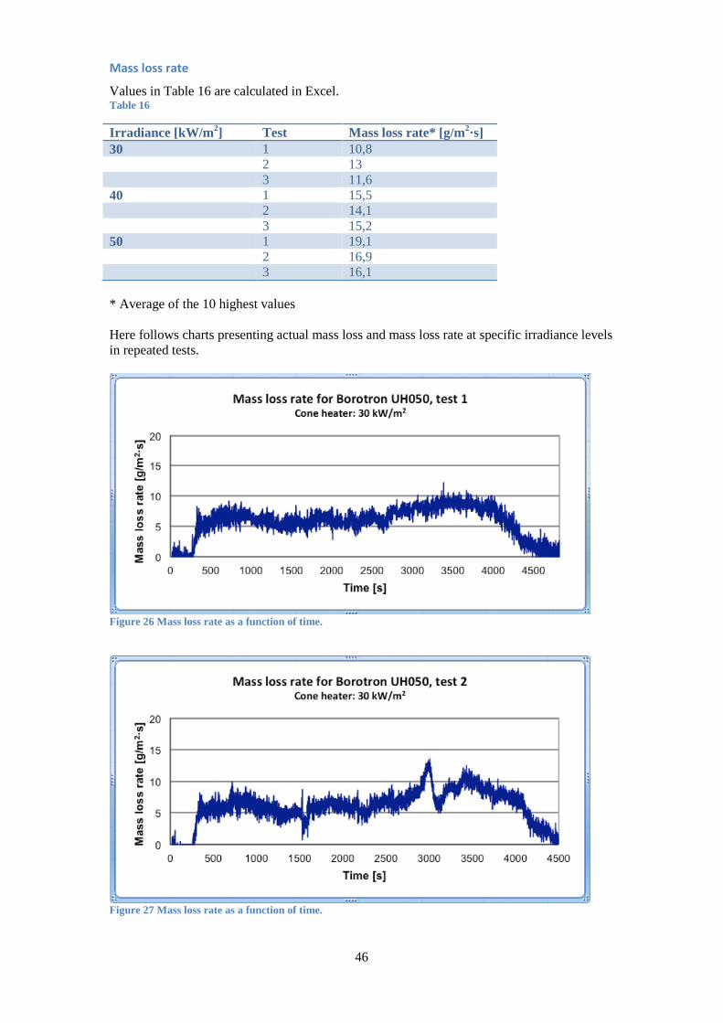
46
Mass loss rate
Values in Table 16 are calculated in Excel. Table 16
Irradiance [kW/m2] Test Mass loss rate* [g/m2·s] 30 1 10,8 2 13 3 11,6 40 1 15,5 2 14,1 3 15,2 50 1 19,1 2 16,9 3 16,1 * Average of the 10 highest values Here follows charts presenting actual mass loss and mass loss rate at specific irradiance levels in repeated tests.
Figure 26 Mass loss rate as a function of time.
Figure 27 Mass loss rate as a function of time.
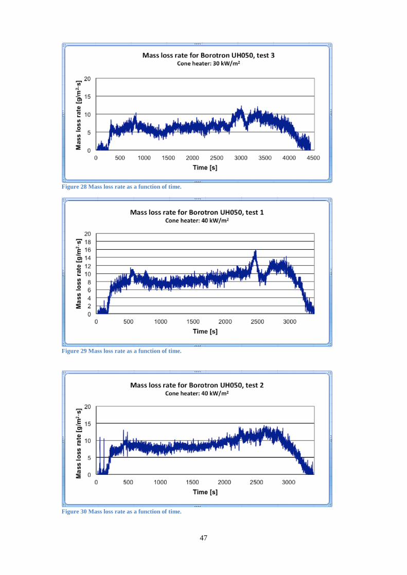
47
Figure 28 Mass loss rate as a function of time.
Figure 29 Mass loss rate as a function of time.
Figure 30 Mass loss rate as a function of time.

48
Figure 31 Mass loss rate as a function of time.
Figure 32 Mass loss rate as a function of time.
Figure 33 Mass loss rate as a function of time.
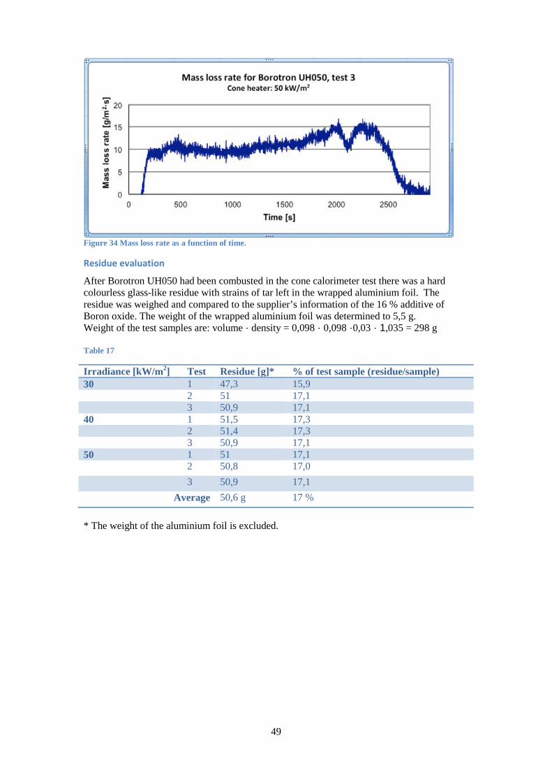
49
Figure 34 Mass loss rate as a function of time.
Residue evaluation
After Borotron UH050 had been combusted in the cone calorimeter test there was a hard colourless glass-like residue with strains of tar left in the wrapped aluminium foil. The residue was weighed and compared to the supplier’s information of the 16 % additive of Boron oxide. The weight of the wrapped aluminium foil was determined to 5,5 g. Weight of the test samples are: volume · density = 0,098 · 0,098 ·0,03 · 1,035 = 298 g Table 17
Irradiance [kW/m2] Test Residue [g]* % of test sample (residue/sample) 30 1 47,3 15,9 2 51 17,1 3 50,9 17,1 40 1 51,5 17,3 2 51,4 17,3 3 50,9 17,1 50 1 51 17,1 2 50,8 17,0 3 50,9 17,1
Average 50,6 g 17 % * The weight of the aluminium foil is excluded.
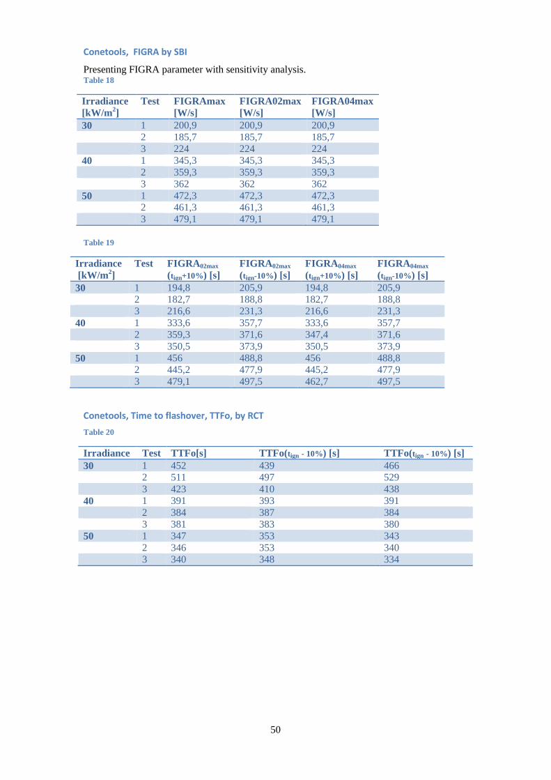
50
Conetools, FIGRA by SBI
Presenting FIGRA parameter with sensitivity analysis. Table 18
Irradiance [kW/m2]
Test FIGRAmax [W/s]
FIGRA02max [W/s]
FIGRA04max [W/s]
30 1 200,9 200,9 200,9 2 185,7 185,7 185,7 3 224 224 224 40 1 345,3 345,3 345,3 2 359,3 359,3 359,3 3 362 362 362 50 1 472,3 472,3 472,3 2 461,3 461,3 461,3 3 479,1 479,1 479,1 Table 19
Irradiance [kW/m2]
Test FIGRA02max (tign+10%) [s]
FIGRA02max (tign-10%) [s]
FIGRA04max (tign+10%) [s]
FIGRA04max (tign-10%) [s]
30 1 194,8 205,9 194,8 205,9 2 182,7 188,8 182,7 188,8 3 216,6 231,3 216,6 231,3 40 1 333,6 357,7 333,6 357,7 2 359,3 371,6 347,4 371,6 3 350,5 373,9 350,5 373,9 50 1 456 488,8 456 488,8 2 445,2 477,9 445,2 477,9 3 479,1 497,5 462,7 497,5
Conetools, Time to flashover, TTFo, by RCT Table 20
Irradiance Test TTFo[s] TTFo(tign - 10%) [s] TTFo(tign - 10%) [s] 30 1 452 439 466 2 511 497 529 3 423 410 438 40 1 391 393 391 2 384 387 384 3 381 383 380 50 1 347 353 343 2 346 353 340 3 340 348 334

51
Conetools, Euroclass according to SBI
Table 21
Irradiance Test Euroclass 30 1 D 2 D 3 D 40 1 D 2 D 3 D 50 1 D 2 D 3 D
Conetools, Total heat release THR600s by SBI Table 22
Irradiance Test THR600s [MJ]
THR600s(tign + 10%) [MJ]
THR600s(tign - 10%) [MJ]
30 1 19,7 19,3 20,1 2 16,9 16,7 17,3 3 23,1 22,7 23,6 40 1 41.3 39,4 43,4 2 43,7 41,8 45,8 3 44,4 42,5 46,4 50 1 63,8 60,9 66,8 2 63,2 60,5 66,1 3 65,9 63,2 69
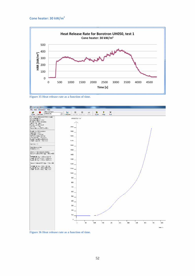
52
Cone heater: 30 kW/m2
Figure 35 Heat release rate as a function of time.
Figure 36 Heat release rate as a function of time.

53
Figure 37 Heat release rate as a function of time.
Figure 38 Heat release rate as a function of time.

54
Figure 39 Heat release rate as a function of time.
Figure 40 Heat release rate as a function of time.

55
Cone heater: 40 kW/m2
Figure 41 Heat release rate as a function of time.
Figure 42 Heat release rate as a function of time.

56
Figure 43 Heat release rate as a function of time.
Figure 44 Heat release rate as a function of time.

57
Figure 45 Heat release rate as a function of time.
Figure 46 Heat release rate as a function of time.

58
Cone heater: 50 kW/m2
Figure 47 Heat release rate as a function of time.
Figure 48 Heat release rate as a function of time.
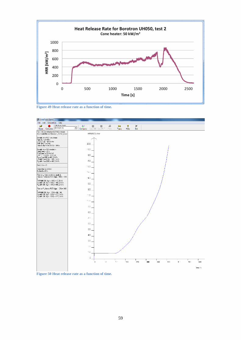
59
Figure 49 Heat release rate as a function of time.
Figure 50 Heat release rate as a function of time.

60
Figure 51 Heat release rate as a function of time.
Figure 52 Heat release rate as a function of time.
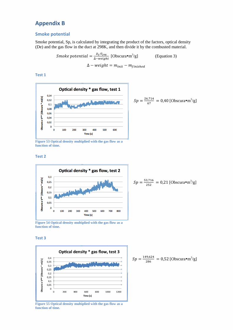
61
Appendix B
Smoke potential Smoke potential, Sp, is calculated by integrating the product of the factors, optical density (De) and the gas flow in the duct at 298K, and then divide it by the combusted material.
𝑆𝑚𝑜𝑘𝑒 𝑝𝑜𝑡𝑒𝑛𝑡𝑖𝑎𝑙 = 𝐷𝑒∙�̇�298Δ−𝑤𝑒𝑖𝑔ℎ𝑡
[Obscuram3/g] (Equation 3)
∆ − 𝑤𝑒𝑖𝑔ℎ𝑡 = 𝑚𝑖𝑛𝑖𝑡 − 𝑚𝑓𝑖𝑛𝑖𝑠ℎ𝑒𝑑
Test 1
𝑆𝑝 = 26,71467
= 0,40 [Obscuram3/g]
Test 2
𝑆𝑝 = 53,716252
= 0,21 [Obscuram3/g]
Test 3
𝑆𝑝 = 149,624286
= 0,52 [Obscuram3/g]
Figure 53 Optical density multiplied with the gas flow as a function of time.
Figure 54 Optical density multiplied with the gas flow as a function of time.
Figure 55 Optical density multiplied with the gas flow as a function of time.
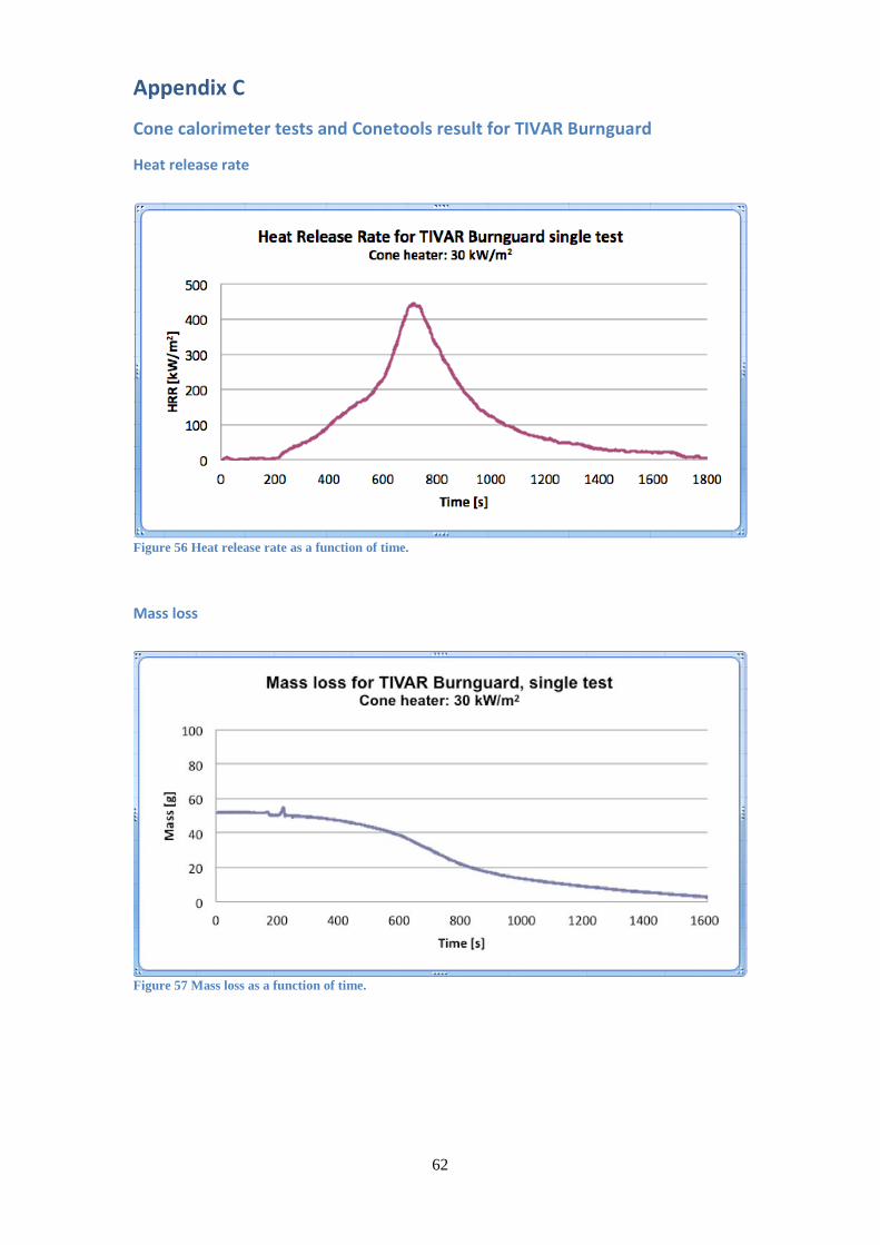
62
Appendix C
Cone calorimeter tests and Conetools result for TIVAR Burnguard
Heat release rate
Figure 56 Heat release rate as a function of time.
Mass loss
Figure 57 Mass loss as a function of time.
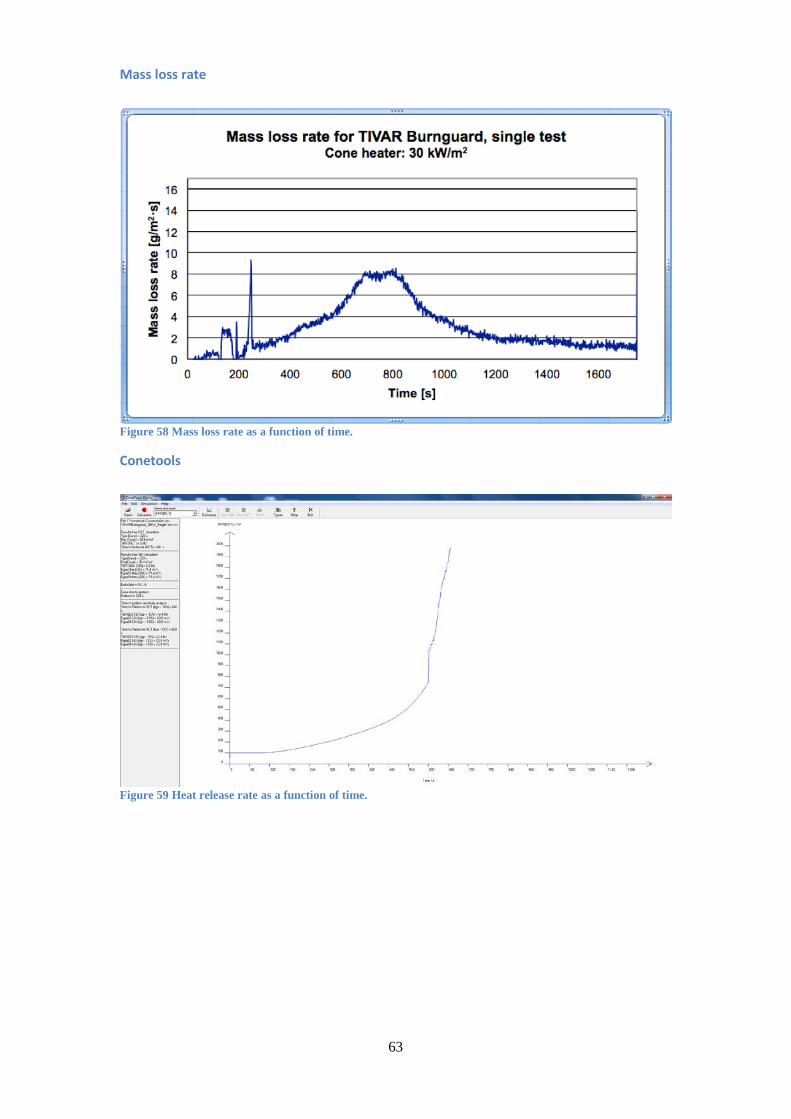
63
Mass loss rate
Figure 58 Mass loss rate as a function of time.
Conetools
Figure 59 Heat release rate as a function of time.
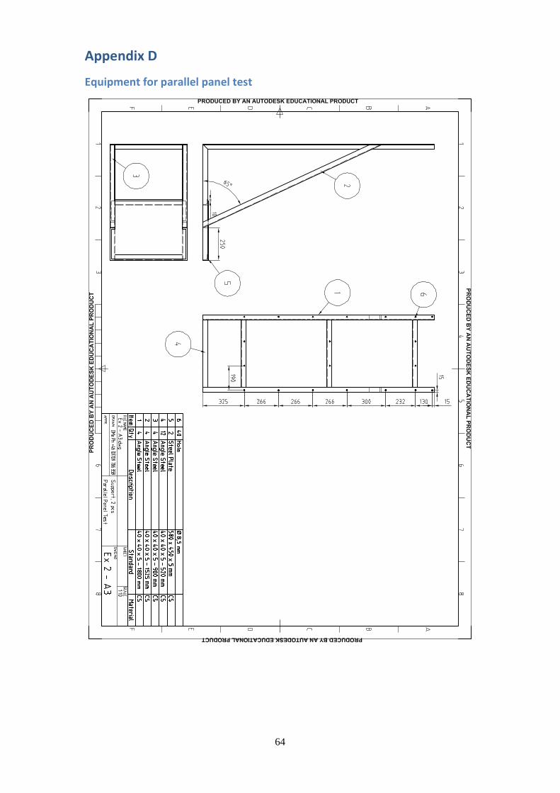
64
Appendix D
Equipment for parallel panel test

65

66
Appendix E
Purchase document Borotron UH050

67
Appendix F
Product Data Sheet Borotron UH050

68
Appendix G Table 23 presents thresholds for classification by European fire classification of materials, construction products and building elements (SP, 2013). Table 23