border gateway protocol (bgp) traffic engineering …njrusmc.net/pubs/nrusso_bts_clean.pdf ·...
TRANSCRIPT

Border Gateway Protocol (BGP) Traffic Engineering Server for
Leaf-Spine Data Center Fabrics Detailed Network Report
February 2017
Version 1.2
Prepared by:
Nicholas Russo
CCDE #20160041
CCIE #42518 (RS/SP)

Nicholas Russo
ii
Review & Approval
Version and Date Change Responsible Person
20160619
Version 1.0
Initial draft release Nicholas Russo
20160621
Version 1.1
Corrections and clarification Nicholas Russo
20170219
Version 1.2
Sanitized for public distribution Nicholas Russo

Nicholas Russo
iii
Contents
1. Leaf/Spine Architecture Overview .......................................................................................... 5
2. BGP Traffic-Engineering ........................................................................................................ 6
2.1. Single TE Path .................................................................................................................. 8
2.2. Multiple TE Paths........................................................................................................... 17
3. Complexity Assessment ........................................................................................................ 20
3.1. State ................................................................................................................................ 20
3.2. Optimization ................................................................................................................... 20
3.3. Surface ............................................................................................................................ 21
4. Other Considerations ............................................................................................................. 22
4.1. IP Multicast .................................................................................................................... 22
4.2. IPv6 ................................................................................................................................ 22
4.3. Routing Security ............................................................................................................. 22
4.4. Standardized Solutions/Protocols ................................................................................... 24
4.5. Topology Limitations ..................................................................................................... 24
Appendix A – Acronyms .............................................................................................................. 25
Appendix B – References ............................................................................................................. 27
Figures
Figure 1 - General Architecture ...................................................................................................... 5
Figure 2 - Elephant Flow Across the Fabric ................................................................................... 7
Figure 3 - BGP TE Server Cluster .................................................................................................. 8
Figure 4 - Controlling the Elephant Flow ..................................................................................... 10
Figure 5 - LFA Inequality 1 .......................................................................................................... 12
Figure 6 - LFA Inequality 2 .......................................................................................................... 13
Figure 7 - LFA Inequality 3 .......................................................................................................... 14
Figure 8 - Splitting the Elephant Flow Across Multiple Paths ..................................................... 19
Figure 9 - Routing Black-Hole when using Connected Next-Hops ............................................. 23

Nicholas Russo
iv
Tables
No table of figures entries found.

Nicholas Russo
5
1. Leaf/Spine Architecture Overview
The popular leaf/spine architecture is based on a circuit-switched network design invented by
Charles Clos and was published in 1952. All links in the fabric are considered “non-blocking”,
which in a packet-switched network, is akin to being “usable for forwarding concurrently”. This
design is commonly used in many DC fabrics today since it maximizes the amount of leaf-to-leaf
bandwidth available in the network. Servers and other devices are only connected to leaves, and
never to spines. Spines only interconnect leaves and offer no services of their own. Devices in
the same array are never connected laterally, either. Adding bandwidth to a leaf/spine
architecture is as simple as scaling out spines. Adding fabric port capacity requires adding
leaves. Both of these two scaling operations are logically simple to accomplish.
The data center (DC) topology for this demonstration is a leaf/spine architecture consisting of a
single array of spines and a single array of leaves. The leaves are drawn in two separate "lines"
for clarity but architecturally, all leaves are equal in terms of hierarchy and purpose.
Figure 1 - General Architecture
R1
SPINES
R2 R3
R4 R5 R6
R7 R8 R9
LEAVES
LEAVES
This document will detail how traffic engineering (TE) can be achieved for IP prefix across the
fabric using Border Gateway Protocol (BGP). BGP runs only on the leaves and is only used for
TE; any interior gateway protocol (IGP) can be used in the fabric for normal forwarding which
uses equal-cost multipath (ECMP) by default. All leaves are configured identically.

Nicholas Russo
6
2. BGP Traffic-Engineering
Using BGP to provide TE inside of a DC is not a new idea. Lapukhov and others have detailed
this in an IETF draft focused on solving large-scale DC routing with BGP, along with TE
mechanisms/solutions. This technique differs from the Lapukhov draft in that IGP is retained in
the fabric and BGP is used for TE only, which is less scalable yet simpler. The Lapukhov draft is
not discussed in detail but is linked in the references section.
Assume that a unidirectional elephant flow exists in the DC flowing from 172.16.1.10 to
172.16.8.3. Combined with other traffic along this forwarding path, this flow has caused
congestion between R1-R4 and between R4-R8. OSPF has informed the RIB of 3 ECMP paths,
and all of them have been installed. The consequence is a FIB with 3 ECMPs which balances
traffic per-source-per-destination. The FIB confirms this.
R1#show ip route 172.16.8.3
Routing entry for 172.16.8.0/24
Known via "ospf 1", distance 110, metric 3, type intra area
Last update from 10.1.4.1 on GigabitEthernet2.514, 00:00:03 ago
Routing Descriptor Blocks:
* 10.1.6.1, from 172.16.8.254, 00:00:03 ago, via GigabitEthernet2.516
Route metric is 3, traffic share count is 1
10.1.5.1, from 172.16.8.254, 00:00:03 ago, via GigabitEthernet2.515
Route metric is 3, traffic share count is 1
10.1.4.1, from 172.16.8.254, 00:00:03 ago, via GigabitEthernet2.514
Route metric is 3, traffic share count is 1
R1#show ipcef 172.16.8.3
172.16.8.0/24
nexthop 10.1.4.1 GigabitEthernet2.514
nexthop 10.1.5.1 GigabitEthernet2.515
nexthop 10.1.6.1 GigabitEthernet2.516
R1#show ipcef exact-route 172.16.1.10 172.16.8.3
172.16.1.10 -> 172.16.8.3 =>IP adj out of GigabitEthernet2.514, addr 10.1.4.1

Nicholas Russo
7
Figure 2 - Elephant Flow Across the Fabric
R1 R2 R3
R4 R5 R6
R7 R8 R9
172.16.1.10
172.16.8.3
CONGESTION
To solve this problem, a set of BGP Traffic-Engineering Servers (BTS) can be used to inject
routes to change the routing path through the fabric. BGP is configured in receive-only mode on
all leaf routers in the fabric and the spines remain BGP-free. Achieving a "BGP-free core" does
not require Multi-Protocol Label Switching (MPLS) or any other tunnelling technologies in this
design. A single autonomous system (AS) is used for simplicity as external BGP (eBGP) does
not offer any additional benefits in this design.
The placement of the BTS in the network is out of scope for this document. It can exist on the
fabric, perhaps directly connected to a set of leaves on a routable server LAN. Or, it can exist on
an out-of-band network to which all spokes have direct access. In this demonstration, the latter
option is chosen.

Nicholas Russo
8
Figure 3 - BGP TE Server Cluster
R1 R2 R3
R4 R5 R6
R7 R8 R9
OUT-OF-BAND
BTS CLUSTER
IBGP
SESSIONS
2.1. Single TE Path
The simplest solution is to inject a single BGP prefix from a single BTS that either offloads the
entire remote network (/24) or a fraction of it. Using a single BTS keeps the configuration simple
but does not provide BTS fault tolerate nor load-sharing.
The BTS injects a longer-match route to shift traffic towards 172.16.8.0/28 across R5. A longer-
match could have been used, but /28 is used for demonstration. Perhaps there are a group of
servers in this range all contributing towards the congestion; supporting variable-length subnets
is more powerful and scalable than host-based TE alone. To achieve TE, the BTS sets the next-
hop to the transit link connected to the remote spine/leaf pair through which traffic should flow.
The example below shows a next-hop of 10.5.8.0, which is covered by the prefix 10.5.8.0/31.
This connects R5 and R8. Also note that the administrative distance has been reduced to 20 for
internal BGP routes; this allows the BTS to totally overwrite an equal-match server LAN if
necessary. It is recommend to inject more specific matches so that the majority of the server
LANs continue to forward using all paths.
R1#show bgp ipv4 unicast 172.16.8.0/28
BGP routing table entry for 172.16.8.0/28, version 6
Nicholas Russo
9
Paths: (1 available, best #1, table default, not advertised to any peer)
Multipath: iBGP
Not advertised to any peer
Refresh Epoch 1
Local
10.5.8.0 (metric 20) from 172.16.255.111 (10.255.0.11)
Origin incomplete, metric 0, localpref 100, valid, internal, best
Community: no-advertise
rxpathid: 0, txpathid: 0x0
R1#show ip route 172.16.8.3
Routing entry for 172.16.8.0/28
Known via "bgp65001", distance 20, metric 0, type internal
Last update from 10.5.8.0 00:00:22 ago
Routing Descriptor Blocks:
* 10.5.8.0, from 172.16.255.111, 00:00:22 ago
Route metric is 0, traffic share count is 1
AS Hops 0
MPLS label: none
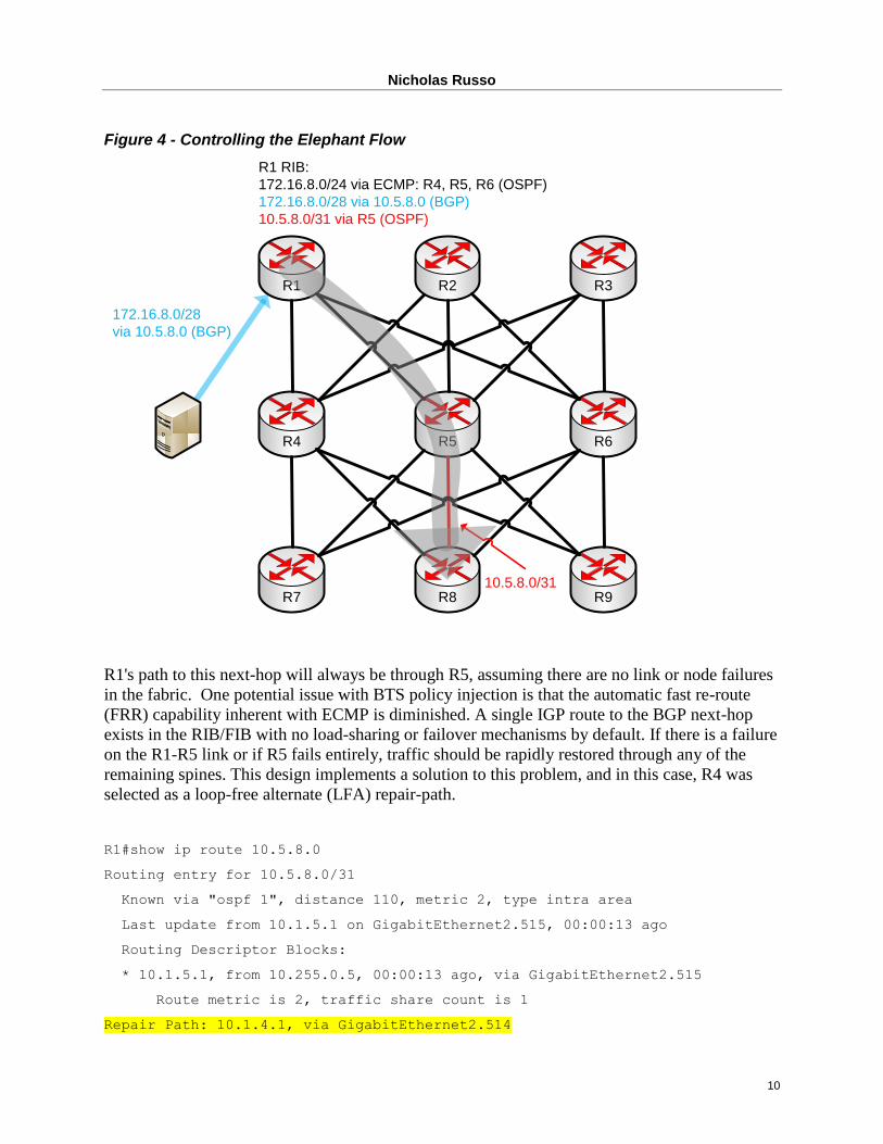
The diagram below depicts this process. Note that the spines remain BGP-free since they will
always route to a leaf LAN via the direct path, so there is no need for them to have longer-
matches injected by the BTS. As such, the spines are insulated from any BTS policy changed in
the fabric.
Nicholas Russo
10
Figure 4 - Controlling the Elephant Flow
R1 R2 R3
R4 R5 R6
R7 R8 R9
172.16.8.0/28
via 10.5.8.0 (BGP)
10.5.8.0/31
R1 RIB:
172.16.8.0/24 via ECMP: R4, R5, R6 (OSPF)
172.16.8.0/28 via 10.5.8.0 (BGP)
10.5.8.0/31 via R5 (OSPF)
R1's path to this next-hop will always be through R5, assuming there are no link or node failures
in the fabric. One potential issue with BTS policy injection is that the automatic fast re-route
(FRR) capability inherent with ECMP is diminished. A single IGP route to the BGP next-hop
exists in the RIB/FIB with no load-sharing or failover mechanisms by default. If there is a failure
on the R1-R5 link or if R5 fails entirely, traffic should be rapidly restored through any of the
remaining spines. This design implements a solution to this problem, and in this case, R4 was
selected as a loop-free alternate (LFA) repair-path.
R1#show ip route 10.5.8.0
Routing entry for 10.5.8.0/31
Known via "ospf 1", distance 110, metric 2, type intra area
Last update from 10.1.5.1 on GigabitEthernet2.515, 00:00:13 ago
Routing Descriptor Blocks:
* 10.1.5.1, from 10.255.0.5, 00:00:13 ago, via GigabitEthernet2.515
Route metric is 2, traffic share count is 1
Repair Path: 10.1.4.1, via GigabitEthernet2.514

Nicholas Russo
11
LFAs are worth a brief discussion since the logic of LFA can be complex. The non-planar yet
symmetrical characteristics of the leaf/spine fabric allow LFA to support the BTS architecture.
Link-state protocols have improved the LFA process over time which relaxes the traditional LFA
criterion used in other protocols. Multiple inequalities (RFC-5286) are used to determine if a
candidate backup path is, in fact, loop-free. Only the first three inequalities apply in this
scenario. The terms S, E, N, and D are used as follows:
S: The source router (R1, the local leaf)
E: The primary next-hop (R5, the primary spine)
N: The candidate next-hops (R4, R6, and any other spines)
D: The destination prefix (R5-R8 link, the BGP next-hop 10.5.8.0/31)
D(X,Y): Function that omputes the IGP “distance” between X and Y
Inequality 1 determines whether a path is an LFA at all:
D(N,D) < D(S,D) + D(N,S)
2 < 2 + 1 --> TRUE
This inequality is relaxing the "feasibility condition" condition used in Cisco's EIGRP.
Distance/path vector protocols cannot evaluate D(N,S) since this relies upon a router to know the
local cost of its connected peer, which is impossible without additional topology information
being carried. For link-state protocols, this information is already known and retained in the link-
state database. The number of potential LFAs through a leaf/spine fabric with X spines is X-1,
yet only one will be selected.

Nicholas Russo
12
Figure 5 - LFA Inequality 1
R1-S
R4-N1 R5-E R6-N2
R8
10.5.8.0/31-D
TESTING R4
D(N1,D) = 2
D(N1,E) = 2
D(E,D) = 1
TESTING R6
D(N2,D) = 2
D(N2,E) = 2
D(E,D) = 1
Inequality 2 is a more strict check on an LFA to see if N is closer to D than S:
D(N,D) < D(S,D)
2 < 2 --> FALSE
This is identical in logic to EIGRP's feasibility condition. If this inequality is true, the LFA is
considered "downstream", which guarantees that micro-loops cannot form in any network.
Within a leaf/spine fabric, assuming all costs are uniform, such micro-loops in these failure
scenarios are impossible anyway. Note that, because this inequality is false, EIGRP would be a
poor choice of IGP for this design since the depicted backup paths can never be LFAs.

Nicholas Russo
13
Figure 6 - LFA Inequality 2
R1-S
R4-N1 R5-E R6-N2
R8
10.5.8.0/31-D
TESTING R4
D(N1,D) = 2
D(S,D) = 2
TESTING R6
D(N2,D) = 2
D(S,D) = 2
Inequality 3 determines whether an LFA is node-protecting:
D(N,S) < D(N,E) + D(E,D)
2 < 2 + 1 --> TRUE
This means that the link R1-R5 or the node R5 can fail and the LFA will protect both cases by
rerouting through R4 or R6. This extra protection ensures that a spine router failure minimally
affects forwarding. The inequality is ensuring that N's path to D does not traverse E, which is
true. Note that when using Intermediate-System to Intermediate-System (IS-IS) with the
overload-bit, D(E,D) cannot be evaluated at all (R4/R6 to R5), as this is a spine-to-spine
calculation. The LFA process cannot consider the LFA as officially node-protecting, even though
it is. Open Shortest Path First (OSPF) is used as the IGP in these demonstrations for clarity
regarding the LFA computation and selection process.

Nicholas Russo
14
Figure 7 - LFA Inequality 3
R1-S
R4-N1 R5-E R6-N2
R8
10.5.8.0/31-D
TESTING R4
D(N1,D) = 2
D(N1,E) = 2
D(E,D) = 1
TESTING R6
D(N2,D) = 2
D(N2,E) = 2
D(E,D) = 1
The output below shows the result of the LFA in question. Note that the LFA is node-protecting
but not downstream. Because the BGP TE mechanisms do not adjust IGP, there is no simple way
to choose one LFA over another when they tie. LFAs need only be computed for BGP next-hops,
which are always the /31 transit links. Individual device loopbacks and server LANs should be
excluded from the LFA calculation to conserve computing resources on leaf devices.
R1#show ipospf rib 10.5.8.0 255.255.255.254 | begin 10.5.8.0
*>10.5.8.0/31, Intra, cost 2, area 0
SPF Instance 10, age 00:00:35
Flags: RIB
via 10.1.5.1, GigabitEthernet2.515
Flags: RIB
LSA: 1/10.255.0.5/10.255.0.5
repair path via 10.1.4.1, GigabitEthernet2.514, cost 3
Flags: RIB, Repair, IntfDj, BcastDj, NodeProt, LoadShare
LSA: 1/172.16.8.254/172.16.8.254
repair path via 10.1.6.1, GigabitEthernet2.516, cost 3
Flags: Ignore, Repair, IntfDj, BcastDj, NodeProt, LoadShare
LSA: 1/172.16.8.254/172.16.8.254

Nicholas Russo
15
The success of the BTS policy and the installation of the LFA is confirmed below. The elephant
flow has been offloaded to R5.
R1#show ipcef 172.16.8.3
172.16.8.0/28
nexthop 10.1.5.1 GigabitEthernet2.515
repair: attached-nexthop 10.1.4.1 GigabitEthernet2.514
R1#show ipcef exact-route 172.16.1.10 172.16.8.3
172.16.1.10 -> 172.16.8.3 =>IP adj out of GigabitEthernet2.515, addr 10.1.5.1
All other traffic destined for 172.16.8.0/24 that falls outside of 172.16.8.0/28 is forwarded using
all paths, as designed. This is the default OSPF behavior which requires no additional
modification and is true for IGPs on most routers.
R1#show ip route 172.16.8.100
Routing entry for 172.16.8.0/24
Known via "ospf 1", distance 110, metric 3, type intra area
Last update from 10.1.4.1 on GigabitEthernet2.514, 00:25:09 ago
Routing Descriptor Blocks:
* 10.1.6.1, from 172.16.8.254, 00:25:09 ago, via GigabitEthernet2.516
Route metric is 3, traffic share count is 1
10.1.5.1, from 172.16.8.254, 00:25:09 ago, via GigabitEthernet2.515
Route metric is 3, traffic share count is 1
10.1.4.1, from 172.16.8.254, 00:25:09 ago, via GigabitEthernet2.514
Route metric is 3, traffic share count is 1
R1#show ipcef 172.16.8.100
172.16.8.0/24
nexthop 10.1.4.1 GigabitEthernet2.514
nexthop 10.1.5.1 GigabitEthernet2.515
nexthop 10.1.6.1 GigabitEthernet2.516

Nicholas Russo
16
The routing lookup on R5, the new transit spine, reveals no new information. The path to R8
remains via the direct R5-R8 link using IGP; this will never change. The spines are guaranteed to
always route traffic correctly whether BGP state exists on the leaves or not.
R5#show ip route 172.16.8.0
Routing entry for 172.16.8.0/24
Known via "ospf 1", distance 110, metric 2, type intra area
Last update from 10.5.8.0 on GigabitEthernet2.558, 1d23h ago
Routing Descriptor Blocks:
* 10.5.8.0, from 172.16.8.254, 1d23h ago, via GigabitEthernet2.558
Route metric is 2, traffic share count is 1
It is worth noting that the reverse path from R8 to R1 remains unchanged. Since the elephant
flow was unidirectional, there is no current need to create symmetric routing across the fabric.
R8 continues to load-share using all available paths, providing higher bandwidth availability and
automatic FRR without LFAs. Both R5 and R8 remain unaware that exception routing has been
introduced. If the elephant flow was bidirectional, the same technique can be used on R8 to
influence its path to R1. This is not demonstrated as the process is identical in the reserve
direction.
R8#show ip route 172.16.1.10
Routing entry for 172.16.1.0/24
Known via "ospf 1", distance 110, metric 3, type intra area
Last update from 10.4.8.1 on GigabitEthernet2.548, 00:38:21 ago
Routing Descriptor Blocks:
* 10.6.8.1, from 172.16.1.254, 00:38:21 ago, via GigabitEthernet2.568
Route metric is 3, traffic share count is 1
10.5.8.1, from 172.16.1.254, 00:38:21 ago, via GigabitEthernet2.558
Route metric is 3, traffic share count is 1
10.4.8.1, from 172.16.1.254, 00:38:21 ago, via GigabitEthernet2.548
Route metric is 3, traffic share count is 1
R8#show ipcef 172.16.1.10
172.16.1.0/24
nexthop 10.4.8.1 GigabitEthernet2.548
nexthop 10.5.8.1 GigabitEthernet2.558
nexthop 10.6.8.1 GigabitEthernet2.568

Nicholas Russo
17
2.2. Multiple TE Paths
For environments requiring granular unequal-cost load-sharing capabilities and/or BTS fault
tolerance, multiple BTS' can be deployed to service a single fabric. The number of BTS' should
be the number of redundancy servers desired or the number of unique paths needed for load
sharing; select whichever number is larger. This environment uses two BTS'; the same prefix is
advertised to R1 so that it can load share between different alternative spines. In this example,
one prefix uses next-hop 10.5.8.0 as seen above, which forces traffic through R5. The other uses
next-hop 10.6.8.0, which forces traffic through R6. The bandwidth extended community is
included so that unequal-cost load-sharing can be signalled from the centralized set of BTS' as
well. The exact values of the bandwidth extended community are irrelevant as only the ratio
matters. Note that omitting the bandwidth extended community would result in ECMP, which is
another valid (but less granular) option.
R1#show bgp ipv4 unicast 172.16.8.0/28
BGP routing table entry for 172.16.8.0/28, version 4
Paths: (2 available, best #2, table default, not advertised to any peer)
Multipath: iBGP
Not advertised to any peer
Refresh Epoch 1
Local
10.6.8.0 (metric 20) from 172.16.255.112 (10.255.0.12)
Origin incomplete, metric 0, localpref 100, valid, internal,
multipath(oldest)
Community: no-advertise
DMZ-Link Bw 2000 kbytes
rxpathid: 0, txpathid: 0
Refresh Epoch 1
Local
10.5.8.0 (metric 20) from 172.16.255.111 (10.255.0.11)
Origin incomplete, metric 0, localpref 100, valid, internal, multipath,
best
Community: no-advertise
DMZ-Link Bw 1000 kbytes
rxpathid: 0, txpathid: 0x0
The result of this unequal-cost weighting ensures that for every 2 flows forwarded through R6, 1
will be forwarded through R5. This technique is useful for further distributing sets of flows
confined to a contiguous subnet across multiple spines. This technique cannot be used to break

Nicholas Russo
18
apart a single flow, so it is best deployed when sets of flows must be exception-routed. All BGP
next-hops will always be protected by node-protecting LFAs for additional fault tolerance as
proven earlier. If, for example, the link between R6-R8 fails, the BGP route is immediately
purged from the table without waiting for a BGP WITHDRAW message from the BTS. This is
the result of IGP removing the prefix from the routing table once convergence is complete. The
remaining BTS paths, such as the one via R5, will be used alone.
R1#show ip route 172.16.8.3
Routing entry for 172.16.8.0/28
Known via "bgp65001", distance 20, metric 0, type internal
Last update from 10.5.8.0 00:01:16 ago
Routing Descriptor Blocks:
* 10.6.8.0, from 172.16.255.112, 00:01:16 ago
Route metric is 0, traffic share count is 2
AS Hops 0
MPLS label: none
10.5.8.0, from 172.16.255.111, 00:01:16 ago
Route metric is 0, traffic share count is 1
AS Hops 0
MPLS label: none
R1#show ip route 10.5.8.0
Routing entry for 10.5.8.0/31
Known via "ospf 1", distance 110, metric 2, type intra area
Last update from 10.1.5.1 on GigabitEthernet2.515, 00:12:21 ago
Routing Descriptor Blocks:
* 10.1.5.1, from 10.255.0.5, 00:12:21 ago, via GigabitEthernet2.515
Route metric is 2, traffic share count is 1
Repair Path: 10.1.4.1, via GigabitEthernet2.514
R1#show ip route 10.6.8.0
Routing entry for 10.6.8.0/31
Known via "ospf 1", distance 110, metric 2, type intra area
Last update from 10.1.6.1 on GigabitEthernet2.516, 00:12:29 ago
Routing Descriptor Blocks:
* 10.1.6.1, from 10.255.0.6, 00:12:29 ago, via GigabitEthernet2.516
Route metric is 2, traffic share count is 1

Nicholas Russo
19
Repair Path: 10.1.5.1, via GigabitEthernet2.515
The diagram below summarizes the relevant forwarding paths.
Figure 8 - Splitting the Elephant Flow Across Multiple Paths
R1 R2 R3
R4 R5 R6
R7 R8 R9
172.16.8.0/28
via 10.5.8.0 (BGP),
Bandwidth = 1000
172.16.8.0/28
via 10.6.8.0 (BGP),
Bandwidth = 2000
10.5.8.0/31
R1 RIB:
172.16.8.0/24 via ECMP: R4, R5, R6 (OSPF)
172.16.8.0/28 via 10.5.8.0 (BW=1000) (BGP)
via 10.6.8.0 (BW=2000) (BGP)
10.5.8.0/31 via R5 (OSPF)
10.6.8.0/31 via R6 (OSPF)
10.6.8.0/31

Nicholas Russo
20
3. Complexity Assessment
This section objectively addresses the complexity of each solution using the
State/Optimization/Surface (SOS) model. This model was formalized by White and
Tantsura(“Navigating Network Complexity: Next-generation routing with SDN, service
virtualization, and service chaining”, R. White / J. TantsuraAddison-Wesley 2016) and is used as
an quantifiable measurement of network complexity. This section is relevant when comparing
the BTS solution to more advanced/complex software-defined networking (SDN) solutions.
3.1. State
State quantifies the amount of control-plane data present and the rate at which state changes in
the network. While generally considered something to be minimized, some network state is
always required. The manner in which a solution scales, typically with respect to time and/or
space complexity, is a good measurement of network state.
The state retained across the fabric scales linearly as nodes are added. Assume that X is the
number of spines and Y is the number of leaves in the fabric:
a. Adding a leaf causes X more links in the topology (one per spine).
b. Adding a spine causes Y more links in the topology (one per leaf).
Thus, adding a node in either role has a linear increase in graphical complexity and the state
required to maintain the graph.
With respect to BTS-injected prefixes, the state is more difficult to assess since the control-plane
is reactive as congestion is detected. A fabric with no congestion has no BGP state, which scales
in constant time/space. A fabric with significant congestion will have significant BGP state,
which scales as poorly as quadratic when computing the product of leaves and prefixes within
the fabric. The most realistic general case is in the middle where each leaf has a few BGP routes
for a few specific destinations. The amount of state is also directly proportional to the
oversubscription ratio. More oversubscription increases the likelihood of more congestion, which
in turns causes more exception routing via BGP.
3.2. Optimization
Unlike state and surface, optimization has a positive connotation and is often the target of any
design. Optimization is a general term that represents the process of meeting a set of design goals
to the maximum extent possible; certain designs will be optimized against certain criteria.
Common optimization designs will revolve around minimizing cost, minimizing convergence
time, minimizing network overhead, maximizing utilization, maximizing manageability,
maximizing user experience, etc.

Nicholas Russo
21
As state increases in the network to avoid congestion in the fabric, optimization is directly
proportional and likewise increases. A network with no BGP state could, in a technical sense, be
called “un-optimized” since no specific path information is used. This “un-optimized” network is
also the ideal state as a fabric without congestion does not require exception routing. The direct
correlation between state and optimization in this architecture represents a clear trade-off. The
sensitivity of the BTS system with respect to injecting prefixes should be set to an appropriate
threshold based on the needs of the network administrator.
3.3. Surface
Surface defines how tightly intertwined components of a network interact. Surface is a two-
dimensional attribute that measures both breadth and depth of interactions between said
components. The breadth of interaction is typically measured by the number of places in the
network some interaction occurs, whereas the depth of interaction helps describe how closely
coupled two things operate.
Surface interactions are kept minimally deep in this network. The spines have almost no surface
interactions between protocols at all since they only run IGP. The leaves rely on BTS-injected
BGP prefixes for TE, which use IGP next-hops. This surface interaction is wide as it exists on all
leaves in the topology, but very shallow since this BGP/IGP interaction is a natural function of
route recursion. Notwithstanding BGP’s assessment of the IGP cost in the best-path selection
algorithm, no other leaky abstractions exist between the two. Other complex surface interactions
such as redistribution are likewise absent.
Routing on the spines is entirely deterministic as they have exactly one path to each leaf. Since
this logic cannot be modified without violating the fundamental logic of a leaf/spine fabric, BGP
is not required on any spine router, so BTS-injected routes are local to a leaf’s BGP process only.

Nicholas Russo
22
4. Other Considerations
4.1. IP Multicast
Since flows are being manually manipulated in the network, Protocol Independent Multicast
(PIM) reverse path forwarding (RPF) paths can be affected. If BTS injects a longer match which
covers a source or rendezvous point (RP), the corresponding (S,G) or (*,G) joins will be re-
issued out of the proper RPF interfaces as needed. This happens as quickly as IGP can converge,
so there are no special considerations for supporting multicast with this design provided the
network remains loop-free.
4.2. IPv6
IPv6 has no special considerations other than feature availability. Some platforms or vendors
may not yet support IP LFA for OSPFv3 or IS-IS IPv6 extensions, while others do. The same is
true for the BGP bandwidth extended community. As such, IPv4 is demonstrated here since the
entire feature set requirement for this architecture is supported on a wider variety of platforms.
4.3. Routing Security
As discussed earlier, all leaves are configured to only receive BGP routes but never advertise
them. The BTS systems should alternatively be configured to only advertise routes and never
receive them. This ensures that the routing exchange occurs in the correct direction. The fabric
leaves can be configured for a maximum prefix limit to protect against memory exhaustion
attacks should the BTS systems be compromised.
Any BTS-injected routes should only use next-hops that are transit /31 links between leaves and
spines in the network. This ensures that maliciously adjusted (or misconfigured) BGP next-hops
advertised outbound from the BTS will have minimal impact. For example, failing to adjust the
next-hop at all would direct traffic towards the BTS itself, which would black-hole traffic and
likely crash the BTS. Setting the BGP next-hop to an incorrect /31 transit link, in the worst case,
directs traffic towards the wrong spine. The spine will always route the packet correctly since it
has exactly one path to each leaf, so the destructiveness of such an attack/misconfiguration is
rather low.
There are two expections to this rule:
a. If a BGP speaker learns a BGP prefix with a next-hop set to one if its local interfaces, the
route is discarded. This is desirable as the fabric ECMP paths will be used instead.
b. If a BGP-speaking leaf learns a BGP prefix with a next-hop set to one of the directly-
connected spine interfaces, forwarding can still work, but new issues arise. In this case,
BGP is selecting only the connected outgoing interface (i.e. spine selection only) yet

Nicholas Russo
23
there is no visibility into the remote spine-to-leaf link. The diagrams below illustrates the
potential black-hole or suboptimal routing issues (depending on RIB entry criteria) that
may result. If the spines are not permitted to route to leaves through other leaves, which
is typical, a black-hole results. If spine-to-spine routing is permitted, a massively
suboptimal forwarding path is formed. To prevent both cases, only non-connected /31
next-hop prefixes are considered valid BGP next-hops.
Figure 9 - Routing Black-Hole when using Connected Next-Hops
R1 R2 R3
R4 R5 R6
R7 R8 R9
172.16.8.0/28
via 10.1.5.1 (BGP)
10.1.5.1
R1 RIB:
172.16.8.0/24 via ECMP: R4, R5, R6 (OSPF)
172.16.8.0/28 via 10.1.5.1 (BGP)
10.1.5.1/31 via R5 (CONNECTED)
LINK
FAIL
R5 CANNOT
REACH R8
Internal BGP route-reflection should not be used anywhere in the network as it is entirely
unnecessary. For additional protection, BTS-injected routes should use the “no-advertise”
community to ensure a leaf uses the TE path only for itself. The BTS must pass both standard
and extended communities to all leaves in order to be effective, but since the leaves need not
advertise any BGP prefixes to the BTS, the opposite is not true.
Note that a total failure of the BGP control-plane means the fabric falls back to ECMP-based
forwarding, which is the best possible fail-back mechanism possible. Congestion points cannot
be effectively mitigated during this failure scenario but the fabric performs as expected in every
other aspect. This is the ideal state of the network since BTS was specifically introduced to
alleviate congestion; a fabric without congestion is operating optimally.

Nicholas Russo
24
4.4. Standardized Solutions/Protocols
No solutions or techniques in this design are proprietary to any vendor. Cisco originally
developed the BGP bandwidth extended community in a draft which has since expired, but other
vendors have implemented it as well given the clear value it brings. Even without this extended
community, equal-cost multi-path or strict BGP failover paths can be used on leaves when
multiple BGP prefixes are injected from a BTS.
4.5. Topology Limitations
This technique can only work in fabrics that have exactly one intermediate router between any
pair of leaves. Additional levels of hierarchy within leaf/spine networks are certainly desirable
for larger-scale DCs, but this technique does not work in such topologies without extending BGP
into the spine. At that point, the problem becomes better solved with a more advanced
centralization technique versus the simple BGP method described in this document. As such, this
architecture is best suited for small to medium DCs using a 3-stage fabric of spines and leaves.

Nicholas Russo
25
Appendix A – Acronyms
Acronym Definition
AS Autonomous System
BGP Border Gateway Protocol
BTS BGP TE Server
DC Data Center
eBGP External BGP
ECMP Equal Cost Multi Path
EIGRP Enhanced Interior Gateway Routing Protocol
FIB Forwarding Information Base
FRR Fast ReRoute
iBGP Internal BGP
IGP Interior Gateway Protocol
IS-IS Intermediate-System to Intermediate-System
LAN Local Area Network
LFA Loop-Free Alternate
MPLS Multi Protocol Label Switching
OSPF Open Shortest Path First
PIM Protocol Independent Multicast
RIB Routing Information Base
RPF Reverse Path Forwarding
RPF Rendezvous Point

Nicholas Russo
26
Acronym Definition
SDN Software Defined Networking
SOS State/Optimization/Surface
TE Traffic Engineering
Nicholas Russo
27
Appendix B – References
OSPF Version 2 (IETF RFC-2328)
IP LFA Selection (IETF RFC-5286)
BGP Bandwidth Extended Community (IETF Draft)
BGP-4 (IETF RFC-4271)
Large Scale DC Routing using BGP (IETF Draft)
Clos Fabric (Wikipedia)
Navigating Network Complexity (White and Tantsura)