bosch viewer 3.0: manual (english)resource.boschsecurity.us/documents/operation_manual_enus...viewer...
TRANSCRIPT
Viewer 3.0
en Operation Guide


Viewer 3.0 Table of Contents | en 3
Bosch Security Systems Operation Guide DOC | 3.0 | 2009.06
Table of Contents
1 Introduction 51.1 About this Manual 51.2 Conventions in this Manual 51.3 Viewer 51.4 System Requirements 61.5 Additional Documentation 6
2 Installation and Starting 72.1 Installation 72.2 Starting the Program 82.3 Deinstallation 82.4 License 82.5 Configuration with Configuration Manager 102.6 Preparing for the Exchange of Encrypted Data 13
3 Operation 153.1 User Interface 163.2 Main Menu 183.2.1 File 183.2.2 Edit 183.2.3 View 183.2.4 Option 193.2.5 Help 193.3 The Monitors 193.3.1 Connection between Camera and Monitor 203.3.2 Additional Information and Controls 223.4 Joystick Panel 243.4.1 Controlling the Camera with the Joystick Panel 243.4.2 Controlling the Camera with the Mouse Cursor 273.5 Software Zoom 303.6 Camera Tours 313.7 Instant Replay 343.8 Exiting the Program 36
4 en | Table of Contents Viewer 3.0
DOC | 3.0 | 2009.06 Operation Guide Bosch Security Systems
4 Appendix 37
Index 38

Viewer 3.0 Introduction | en 5
Bosch Security Systems Operation Guide DOC | 3.0 | 2009.06
1 Introduction
1.1 About this ManualThis manual is intended for persons who will operate the Viewer program. The manual describes how to operate Viewer.
1.2 Conventions in this ManualIn this manual, the following symbols and notations are used to draw attention to special situations:
Terms that you can find in the program, such as menu options or commands, are written in bold.
1.3 ViewerViewer is a piece of software that is used to show digital video sequences. Viewer displays video data from several cameras on the PC monitor, allowing the data to be monitored centrally from a single workstation.Without a license, it can be used with up to 16 connected cameras. This setup makes Viewer suitable for protecting small retail businesses.
CAUTION! Security instructions where non-compliance can result in loss of data are marked with this symbol.
NOTICE! This symbol indicates special features and provides tips and information for easier, more convenient use of the software.
6 en | Introduction Viewer 3.0
DOC | 3.0 | 2009.06 Operation Guide Bosch Security Systems
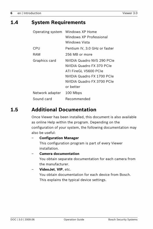
1.4 System Requirements
1.5 Additional DocumentationOnce Viewer has been installed, this document is also available as online Help within the program. Depending on the configuration of your system, the following documentation may also be useful:– Configuration Manager
This configuration program is part of every Viewer installation.
– Camera documentationYou obtain separate documentation for each camera from the manufacturer.
– VideoJet, VIP, etc.You obtain documentation for each device from Bosch. This explains the typical device settings.
Operating system Windows XP HomeWindows XP ProfessionalWindows Vista
CPU Pentium IV, 3.0 GHz or faster
RAM 256 MB or more
Graphics card NVIDIA Quadro NVS 290 PCIeNVIDIA Quadro FX 370 PCIeATI FireGL V5600 PCIeNVIDIA Quadro FX 1700 PCIeNVIDIA Quadro FX 3700 PCIeor better
Network adapter 100 Mbps
Sound card Recommended

Viewer 3.0 Installation and Starting | en 7
Bosch Security Systems Operation Guide DOC | 3.0 | 2009.06
2 Installation and Starting
2.1 InstallationViewer is installed as a component of the Bosch BVIP Lite Suite. Configuration Manager is also installed in conjunction with these programs.1. Close all other applications before beginning the
installation.2. Insert the installation CD into the computer's CD-ROM
drive. The CD runs automatically.If the CD does not run automatically, open the index.html page from the root.
3. Select the required language for the user interface.4. Click one of the entries under Installation Packages to
start installing the relevant installation package. You will be guided through the installation of each individual package.
5. When installing individual packages, several installation processes will run one after the other where necessary.During installation, you will be prompted to select target directories for the programs. It is advisable to accept the defaults.
When selecting components, a description for each one is displayed when you hover the mouse cursor over them.If individual programs are already installed on your PC, you can exclude these from the installation in the Choose Components dialog.Please note that the Configuration Manager program is needed to set up a Viewer workstation.After successful installation, you will find icons on your desktop for:– Viewer– Archive Player– Player– Configuration Manager

8 en | Installation and Starting Viewer 3.0
DOC | 3.0 | 2009.06 Operation Guide Bosch Security Systems
In the start menu, these entries appear under Bosch BVIP Lite Suite.
2.2 Starting the ProgramAfter successful installation, you will find the following icon on your desktop:
Double click this icon to start the program.Viewer can also be started via the Windows Start menu or from within the Configuration Manager program.You can use Configuration Manager to set up user administration. A login dialog appears, where applicable. Before you can start the program, you must log in here using your user name and the associated password.
2.3 DeinstallationIf you no longer want to use Viewer on your PC, uninstall the program.1. Click Start > Settings > Control Panel.2. Double-click Add or Remove Programs.3. Select the Bosch Viewer entry.4. Click Remove.
2.4 LicenseYou can use the Viewer program with up to 16 video channels without a license. A video channel is defined as any directly connected IP camera and any video input integrated via a video encoder. A four-channel encoder therefore occupies four Viewer channels, even if only one camera is connected to it. If you wish to integrate more than 16 video channels into your system, you will require a license.
Viewer 3.0 Installation and Starting | en 9
Bosch Security Systems Operation Guide DOC | 3.0 | 2009.06
License management for Viewer is carried out using the Configuration Manager program on the PC that is to be licensed.1. Start the Configuration Manager program on the PC you
want to license.2. Click Help > Online Help....3. In the About Configuration Manager dialog box, click the
Licenses tab and then License Viewer....You will see the License Viewer window.
4. Make a note of the Installation Code (Code 2) entry – the copy-and-paste function is supported. You will need this to generate the activation keys for your license.
5. Open the following Website from any PC:https://activation.boschsecurity.com/The Bosch Security Systems Software License Manager user interface will appear. The page appears in English only.
6. If you already have an account, log in.You can create a new account if you wish. The benefit of an account is that you can list all of your previous license activations.Once you have logged in, the welcome dialog will appear.You can also continue the process without logging in.Next, you will see the License Activation screen.
7. Generate the required activation keys.8. Return to Configuration Manager.9. Reopen the License Viewer window as described in steps
2 and 3.10. Click Activation Key and enter the first activation key
(Activation Key 1) – the copy-and-paste function is supported.
NOTICE! When you purchase products that require a license, you will receive a separate authorization number for each license and workstation; you will also need this number to generate the relevant activation keys.
10 en | Installation and Starting Viewer 3.0
DOC | 3.0 | 2009.06 Operation Guide Bosch Security Systems
11. Click OK to save the activation key.12. Repeat this process to save the second activation key
(Activation Key 2).This releases the license version.
You can use the License Viewer at any time to determine which license version is active on the PC in question.
2.5 Configuration with Configuration ManagerThe Configuration Manager program is installed along with the Viewer program. You can use Configuration Manager to integrate devices into the system and to configure devices and cameras.
The Configuration Manager program comes complete with extensive documentation containing information about the use of the program.The Configuration Manager program also includes the following settings, which affect Viewer:1. In the Configuration Manager program, click the System
tab on the left-hand side.
CAUTION! The license is linked to your PC. If you have uninstalled Viewer and then want to reinstall it on a different PC, you will need to request a new activation key.
NOTICE! Viewer can only access cameras and devices that have been integrated into the system using the Configuration Manager program.

Viewer 3.0 Installation and Starting | en 11
Bosch Security Systems Operation Guide DOC | 3.0 | 2009.06
2. In the tree structure, select Applications > Viewer:
You will find the following configuration options on the right-hand side:– Maximum concurrent decoder instances
Here you can set how many video streams can be shown simultaneously in real time in Viewer. You can also open further monitors and add connections; how-ever, these are only displayed as preview screens. In this way, you can limit the network load.
– Lip syncIf this option is activated, audio and video data is syn-chronized, meaning that there may be a delay when transferring audio data, depending on the connection.
– "Instant Replay" time range (min)Here, you enter the time for which you want instant replay to be displayed.
– Show VCA metadataWhen a video is displayed in Viewer, the video content analysis metadata, such as object outlines, is also dis-played if this option is activated.
– Animate monitor layout changeThis function is switched on and off here.
– Automatic device reconnectionIf this option is activated, all the connections that were last enable are automatically restored when Viewer is restarted.

12 en | Installation and Starting Viewer 3.0
DOC | 3.0 | 2009.06 Operation Guide Bosch Security Systems
3. In the tree structure, select General > Directories.You will find the following configuration options on the right-hand side:– Screenshot folder
Select the storage location for screenshots that you make with Viewer.
– Recording folderSelect the storage location for video recordings that you make with Viewer.
If you do not enter anything here, the following default settings are used:– %current user%\My Documents
\Bosch\VIDOS\Snapshots
and
– %current user%\My Documents\Bosch\VIDOS\Recordings
4. In the tree structure, select General > Client/Server.On the iSCSI Media tab, enter the password for accessing recordings. This is necessary to enable instant replay with Viewer.
5. In the tree structure, select General > Hardware Monitors.Hardware monitors are video monitors that are integrated into the system via video decoders. Software monitors are the monitors displayed in the Viewer playback window. You can use this matrix to permanently connect hardware and software monitors to one another. This means that as soon as a software monitor that is connected in this way is activated in Viewer, the image is also displayed on the associated hardware monitor.For details on this function, see the Configuration Manager documentation.
6. In the tree structure, select Applications > Configuration Manager.On the Appearance tab, you can activate the Prefix device name to camera name option. In the case of cameras that are integrated into the system via video encoders, the

Viewer 3.0 Installation and Starting | en 13
Bosch Security Systems Operation Guide DOC | 3.0 | 2009.06
encoder device name is also displayed before the camera name in the camera list.The encoder name can therefore be included when you are filtering the camera list (see: Section Tree Filter, page 20).
Grouping CamerasConfiguration Manager allows you to arrange cameras into clear groups. You can then see the grouping in Viewer.For details on this function, see the Configuration Manager documentation.
Configuring DevicesUse Configuration Manager to configure devices integrated into the system. The settings include:– Device and camera name– Passwords for device access– Display stamping (alarm, camera name, time stamp)– Device network settings, IP address– Encoder parameters– Alarm settings– Recording settings– Camera controller
2.6 Preparing for the Exchange of Encrypted DataTo enable playback of encrypted data with Viewer, you must adapt the settings for the relevant sender using Configuration Manager.1. Select the Devices main tab in the Configuration Manager
program and highlight the appropriate senders.2. Make sure the File > Advanced Mode option is active.3. Select the Network tab from the display area, or the
Advanced Network tab for devices with firmware version 4.0 and better.Activate the Automatic key interchange option under Encryption.
Click to save the settings.
14 en | Installation and Starting Viewer 3.0
DOC | 3.0 | 2009.06 Operation Guide Bosch Security Systems
4. Select the Unit Access tab.Select the HTTPS setting from the Protocol list field under Device access.
Click to save the settings.

Viewer 3.0 Operation | en 15
Bosch Security Systems Operation Guide DOC | 3.0 | 2009.06
3 OperationIn the Viewer program, you have access to all cameras that have previously been integrated into the system using Configuration Manager. Configuration Manager allows you to combine cameras into groups, for example according to location. For more information, please see the Configuration Manager documentation.Viewer is an easy and intuitive program to operate; it can be used to control cameras in a CCTV system and display live video data on the PC monitor. Video sequences or screenshots can be recorded locally. Virtual tours (camera tours) can be created to automate surveillance.Use Archive Player to view and export the available recordings.

16 en | Operation Viewer 3.0
DOC | 3.0 | 2009.06 Operation Guide Bosch Security Systems
3.1 User Interface
1 Joystick panel(see: Section 3.4 Joystick Panel, page 24)
2 Software zoom(see: Section 3.5 Software Zoom, page 30)
3 Camera tours(see: Section 3.6 Camera Tours, page 31)
4 Instant replay(see: Section 3.7 Instant Replay, page 34)
5 Playback window with monitorsThe active monitor is outlined in green.
6 Switches to Archive Player
7 Switches to Configuration Manager

Viewer 3.0 Operation | en 17
Bosch Security Systems Operation Guide DOC | 3.0 | 2009.06
To hide or show the buttons for individual monitors, press the F9 key (see: Section Functions on the Monitor, page 22).You can increase the space for the playback window by placing the mouse at the bottom edge of the playback window until the cursor changes into the following symbol:
With the mouse button held down, drag the bottom edge of the playback window up or down. The alarm message list is increased or decreased and the size of the playback window changes accordingly. The number of monitors being displayed is also adjusted variably. All monitors that can still be displayed in full screen view on the PC monitor are shown in light gray.
8 Gradually adjusts the volume
9 CPU load display
10 Current date and time
11 Filter for the camera list (can be displayed if required)(see: Section Tree Filter, page 20)
12 Camera listThe popup menu allows you to copy the camera list to the clipboard.
13 Display and operating field for the digital inputs and outputs of the remote station of the currently active monitor (can be displayed if required)
14 List of alarm messages
15 Opens the folder for recordings in Windows Explorer
16 Opens the folder for screenshots in Windows Explorer
17 Allows you to select another monitor layout(see: Section Changing the Monitor Layout, page 22)

18 en | Operation Viewer 3.0
DOC | 3.0 | 2009.06 Operation Guide Bosch Security Systems
3.2 Main MenuBelow are the lists of commands available in the main menu. Some of the functions can also be called up via key combinations or function keys.
3.2.1 File
3.2.2 Edit
3.2.3 View
Exit Closes the program
Save Screenshots(P)
Saves screenshots from all connected monitors in the specified folder
Print Screenshots...(Alt+P)
Saves screenshots from all connected monitors in the specified folder and prints them on the PC's default printer
Send Screenshots...
Saves screenshots from all connected monitors in the specified folder and sends them to the selected e-mail addresses
Record Active Monitor(Alt+E)
Starts or stops the recording of the active monitor.Once a recording reaches 2 GB in size, it is automatically stopped.
Record Active MonitorF9
Hides or shows the buttons for the individual monitors
Single ViewF10
Switches between the current monitor layout and a layout with only one monitor, namely the active one
Full ScreenF12
Switches between full screen display and window view

Viewer 3.0 Operation | en 19
Bosch Security Systems Operation Guide DOC | 3.0 | 2009.06
3.2.4 Option
3.2.5 Help
3.3 The MonitorsViewer makes one or more software monitor windows available. These can be displayed in various layouts in the playback window.Each one of these monitors corresponds to a software decoder. To avoid overloading the network and PC, it is possible to limit the number of simultaneous decoding instances in Configuration Manager (see: Section 2.5 Configuration with Configuration Manager, page 10).The number specified here does not limit the number of monitors. It defines the number of connections that can be transmitted in real time. For each connection exceeding the specified number, the monitor simply displays regularly updated preview screens for the connected camera.
Layout Allows you to select another monitor layout (see: Section Changing the Monitor Layout, page 22)
Watermarking Switches the display of additional information on or off on all monitors
Digital I/O Hides or shows the display and operating field for the digital inputs and outputs of the remote station below the camera list (see: Section Digital I/O, page 21)
Tree Filter Hides or shows the filter above the camera list (see: Section Tree Filter, page 20)
Online Help... Opens the online Help
About... Provides information about the software version

20 en | Operation Viewer 3.0
DOC | 3.0 | 2009.06 Operation Guide Bosch Security Systems
Displays in the various tabs and commands that are triggered via the tabs (for example, camera control via the joystick panel) are always related to the active monitor.To activate a monitor, click it with the mouse.The active monitor is indicated by the green outline. The monitor has a flashing red outline when an alarm event is triggered.
3.3.1 Connection between Camera and MonitorAfter starting Viewer, you must connect individual monitors with cameras.All cameras integrated into the system are displayed in the camera list. You can make the display clearer by using the name filter (see: Section Tree Filter, page 20)1. Select a camera from the camera list.2. Hold the left mouse button down and drag the camera
onto one of the monitors:
While the connection is being established, a status message to that effect appears on the monitor.
Tree FilterThis input field is hidden or displayed via Option > Tree Filter.Here you can filter by camera name, to limit the display in the camera list to certain cameras.1. Enter a search combination in the input field, using letters,
numbers and spaces.Only cameras with this combination in their name will be displayed.
2. Click to display all available cameras again.In Configuration Manager, you can specify that when the camera is connected via a video encoder, the name of this

Viewer 3.0 Operation | en 21
Bosch Security Systems Operation Guide DOC | 3.0 | 2009.06
device is automatically placed before the camera name (see: Section 2.5 Configuration with Configuration Manager, page 10).
Digital I/OSelect Option > Digital I/O to hide or show the display field for the digital inputs and outputs of the remote station below the camera list. The display relates to the active monitor. The number of inputs and outputs displayed depends on the device and its configuration.
The round alarm icons (in the top row of the example) indicate the status of an alarm input for information purposes. If an alarm exists, the corresponding icon lights up. The configuration of the remote station determines whether alarms are displayed or not.
Triggering RelayThe square relay icons (in the bottom row of the example) can be used to switch connected devices (for example, lights or door openers).
To activate it, click the icon for the corresponding relay.The icon will be green when the relay is activated.
Audio FunctionIf the remote station that belongs to the active monitor supports audio, Viewer can send and receive audio. All connected users receive audio signals sent from the remote station.Only the user who first connected to the unit can send audio signals to the remote station.1. Hold down the F4 key to establish a voice connection with
the remote station.
22 en | Operation Viewer 3.0
DOC | 3.0 | 2009.06 Operation Guide Bosch Security Systems
2. Release the F4 key when you want to stop sending audio signals to the remote station.
3.3.2 Additional Information and Controls
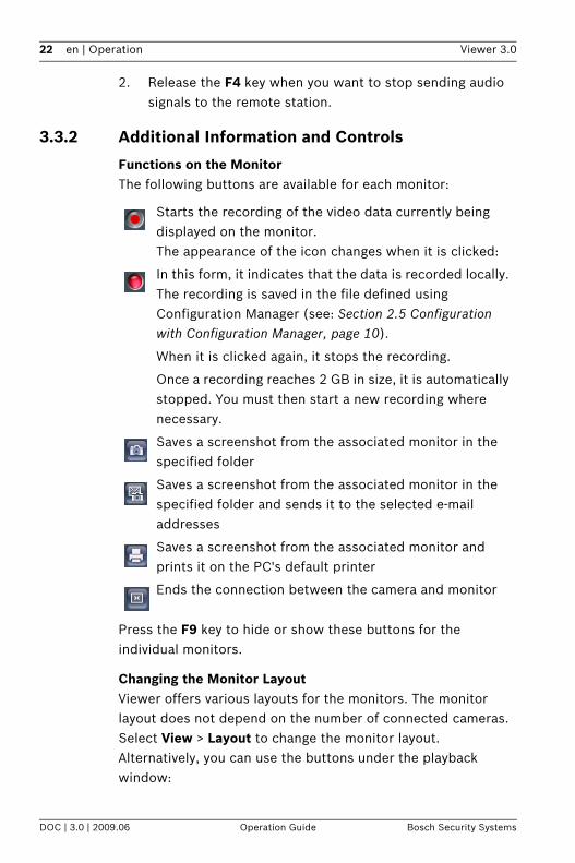
Functions on the MonitorThe following buttons are available for each monitor:
Press the F9 key to hide or show these buttons for the individual monitors.
Changing the Monitor LayoutViewer offers various layouts for the monitors. The monitor layout does not depend on the number of connected cameras. Select View > Layout to change the monitor layout.Alternatively, you can use the buttons under the playback window:
Starts the recording of the video data currently being displayed on the monitor.The appearance of the icon changes when it is clicked:
In this form, it indicates that the data is recorded locally. The recording is saved in the file defined using Configuration Manager (see: Section 2.5 Configuration with Configuration Manager, page 10).
When it is clicked again, it stops the recording.
Once a recording reaches 2 GB in size, it is automatically stopped. You must then start a new recording where necessary.
Saves a screenshot from the associated monitor in the specified folder
Saves a screenshot from the associated monitor in the specified folder and sends it to the selected e-mail addresses
Saves a screenshot from the associated monitor and prints it on the PC's default printer
Ends the connection between the camera and monitor

Viewer 3.0 Operation | en 23
Bosch Security Systems Operation Guide DOC | 3.0 | 2009.06
1. Click .All possible layouts are displayed:
2. Select the required layout.The layout in the playback window is adjusted accordingly.
In Configuration Manager, you can specify under Animate monitor layout change that monitor layout changes should be animated. This allows you to trace the position changes of individual monitors (see: Section 2.5 Configuration with Configuration Manager, page 10).To change the layout of individual monitors, hold the mouse button down and drag a monitor to a different position.
Full Screen DisplayPress F12 to switch between the program interface and full screen display.Depending on the selected display, up to 25 camera images are also displayed in full screen display.In full screen display, you can also control the camera with the mouse. In addition, it is possible to print, save or send a screenshot, or to start a recording.

24 en | Operation Viewer 3.0
DOC | 3.0 | 2009.06 Operation Guide Bosch Security Systems
3.4 Joystick PanelControllable cameras are moved and controlled directly from Viewer. This requires the selected camera to be correctly connected and appropriately configured. If the camera is connected via a video encoder, the appropriate controller must be selected in Configuration Manager (details can be found in the separate Configuration Manager documentation).
3.4.1 Controlling the Camera with the Joystick PanelThe joystick panel offers a range of functions for camera control. The scope depends on what functions the camera supports.
1 Panning direction keys
2 Tilting direction keys
3 Joystick
4 Zoom
5 Presets
6 Hide/show advanced options
7 Advanced camera control options

Viewer 3.0 Operation | en 25
Bosch Security Systems Operation Guide DOC | 3.0 | 2009.06
1. Display the joystick panel in the top left-hand corner of the screen.
2. Click one of the green direction keys.The camera moves in the appropriate direction for as long as the key remains pressed.
3. Hold the joystick with the mouse and control the camera intuitively.
4. Click or to maximize or minimize the scene (zoom).A short click near the edge of the joystick just moves the camera a fraction.
Accessing PresetsPresets are fixed camera positions. Presets can be saved (see: Section Functions Tab, page 26). The list of presets is shown under the joystick panel.
Click , or .
The camera moves to the preset position.Presets are saved separately for each camera. If you select a monitor to which another camera is allocated, other presets will be displayed.
Additional OptionsYou can configure further camera control settings under the joystick panel.
Click . The additional options are shown.
26 en | Operation Viewer 3.0
DOC | 3.0 | 2009.06 Operation Guide Bosch Security Systems
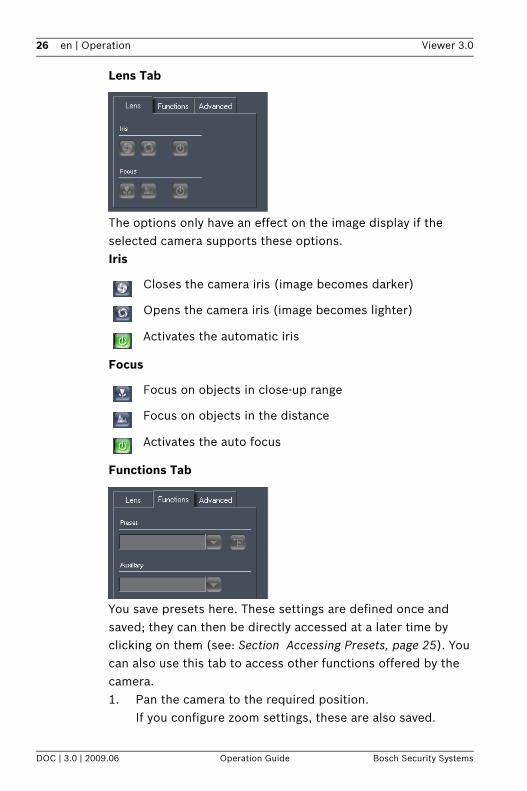
Lens Tab
The options only have an effect on the image display if the selected camera supports these options.Iris
Focus
Functions Tab
You save presets here. These settings are defined once and saved; they can then be directly accessed at a later time by clicking on them (see: Section Accessing Presets, page 25). You can also use this tab to access other functions offered by the camera.1. Pan the camera to the required position.
If you configure zoom settings, these are also saved.
Closes the camera iris (image becomes darker)
Opens the camera iris (image becomes lighter)
Activates the automatic iris
Focus on objects in close-up range
Focus on objects in the distance
Activates the auto focus
Viewer 3.0 Operation | en 27
Bosch Security Systems Operation Guide DOC | 3.0 | 2009.06
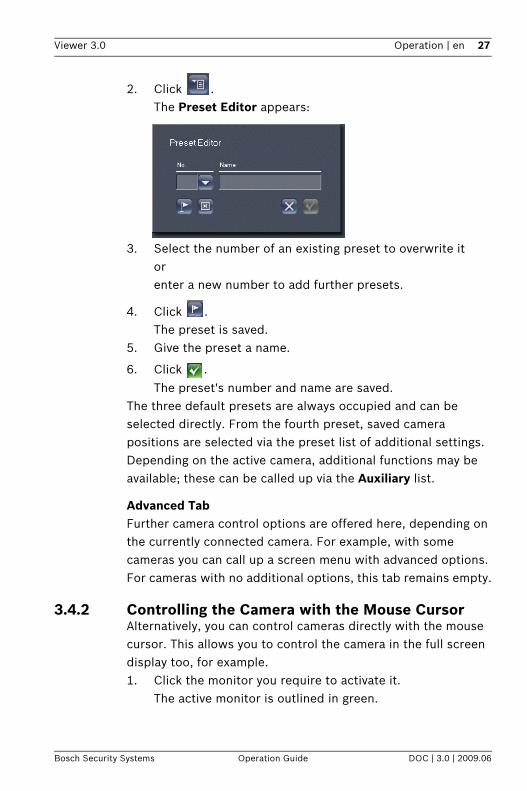
2. Click .The Preset Editor appears:
3. Select the number of an existing preset to overwrite itorenter a new number to add further presets.
4. Click .The preset is saved.
5. Give the preset a name.
6. Click .
The preset's number and name are saved.The three default presets are always occupied and can be selected directly. From the fourth preset, saved camera positions are selected via the preset list of additional settings.Depending on the active camera, additional functions may be available; these can be called up via the Auxiliary list.
Advanced TabFurther camera control options are offered here, depending on the currently connected camera. For example, with some cameras you can call up a screen menu with advanced options.For cameras with no additional options, this tab remains empty.
3.4.2 Controlling the Camera with the Mouse CursorAlternatively, you can control cameras directly with the mouse cursor. This allows you to control the camera in the full screen display too, for example.1. Click the monitor you require to activate it.
The active monitor is outlined in green.

28 en | Operation Viewer 3.0
DOC | 3.0 | 2009.06 Operation Guide Bosch Security Systems
2. Move the cursor to the right or left edge of the monitor.The cursor changes into an arrow:
3. Click the mouse button for short movementsorhold the mouse button down for longer range panning.
4. Move the cursor to the top or bottom edge of the monitor.The cursor changes into an arrow:
5. Click the mouse button for short movementsorhold the mouse button down for longer range tilting.
6. Move the cursor to a corner of the monitor. The cursor changes into an arrow.

Viewer 3.0 Operation | en 29
Bosch Security Systems Operation Guide DOC | 3.0 | 2009.06
7. Click the mouse button for short movementsorhold the mouse button down for longer diagonal camera movements.
8. Use the mouse scroll wheel to zoom in or out:– If you scroll the wheel up, the cursor changes into a
magnifying glass with a plus sign, and the camera zooms in:
– If you scroll the wheel down, the cursor changes into a magnifying glass with a minus sign, and the camera zooms out:

30 en | Operation Viewer 3.0
DOC | 3.0 | 2009.06 Operation Guide Bosch Security Systems
3.5 Software ZoomThe digital zoom tool allows you to display an enlarged view of a view port.
1. Click Activate zoom to use the software zoom on the image on the active monitor.
2. Move the mouse into the green rectangle. When the mouse cursor changes, you can hold down the left mouse button and move the rectangle to display a different view port on the active monitor.
3. Drag any corner or side of the rectangle with the left mouse button held down to change the size of the selection rectangle.The view port on the active monitor changes accordingly.
4. Click Reset view port to display the selection rectangle at the preset size and in the center.
5. Click Deactivate zoom to show the entire image from the camera on the active monitor again.
You can display the data from the same camera several times by connecting the same camera with several monitors; this allows you to enlarge different extracts.
1 View port displayed with active zoom
2 Activate zoom/Deactivate zoom
3 Reset view port

Viewer 3.0 Operation | en 31
Bosch Security Systems Operation Guide DOC | 3.0 | 2009.06
3.6 Camera ToursA camera tour is the recording of a defined sequence of changing camera allocations to a single monitor. A camera tour is a virtual tour. You can create up to eight camera tours in Viewer.
When a camera tour is called up, video data from different cameras is shown in sequence on the active monitor. This allows you to systematically supervise a large area monitored by several cameras.
Calling up a Camera Tour1. Click the monitor you require to activate it.
The active monitor is outlined in green.2. In the list, click the number before the camera tour you
require.The camera tour starts in the active monitor.
1 List of camera tours
2 Show/hide Camera Tour Editor
3 Camera Tour Editor
32 en | Operation Viewer 3.0
DOC | 3.0 | 2009.06 Operation Guide Bosch Security Systems
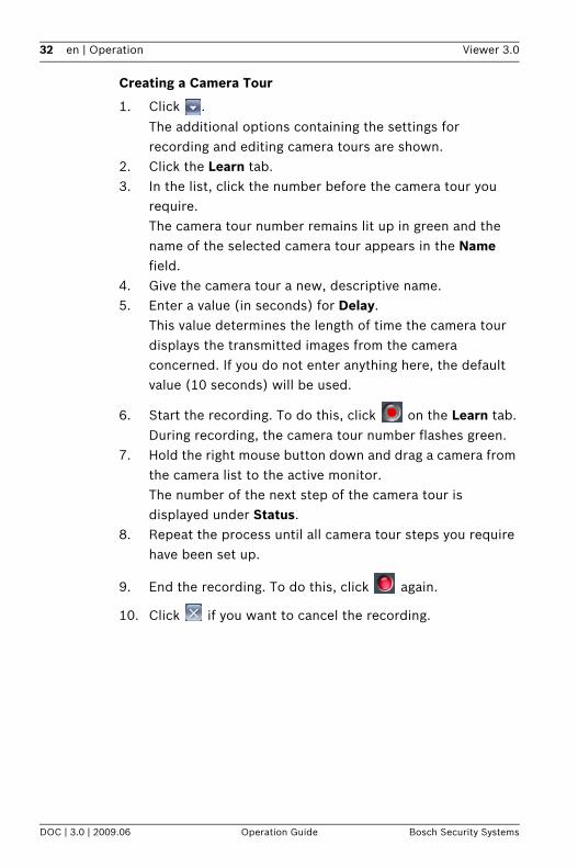
Creating a Camera Tour
1. Click .
The additional options containing the settings for recording and editing camera tours are shown.
2. Click the Learn tab.3. In the list, click the number before the camera tour you
require.The camera tour number remains lit up in green and the name of the selected camera tour appears in the Name field.
4. Give the camera tour a new, descriptive name.5. Enter a value (in seconds) for Delay.
This value determines the length of time the camera tour displays the transmitted images from the camera concerned. If you do not enter anything here, the default value (10 seconds) will be used.
6. Start the recording. To do this, click on the Learn tab.During recording, the camera tour number flashes green.
7. Hold the right mouse button down and drag a camera from the camera list to the active monitor.The number of the next step of the camera tour is displayed under Status.
8. Repeat the process until all camera tour steps you require have been set up.
9. End the recording. To do this, click again.
10. Click if you want to cancel the recording.
Viewer 3.0 Operation | en 33
Bosch Security Systems Operation Guide DOC | 3.0 | 2009.06
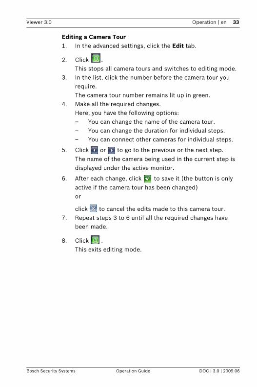
Editing a Camera Tour1. In the advanced settings, click the Edit tab.
2. Click .This stops all camera tours and switches to editing mode.
3. In the list, click the number before the camera tour you require. The camera tour number remains lit up in green.
4. Make all the required changes.Here, you have the following options:– You can change the name of the camera tour.– You can change the duration for individual steps.– You can connect other cameras for individual steps.
5. Click or to go to the previous or the next step.
The name of the camera being used in the current step is displayed under the active monitor.
6. After each change, click to save it (the button is only
active if the camera tour has been changed)or
click to cancel the edits made to this camera tour.7. Repeat steps 3 to 6 until all the required changes have
been made.
8. Click .This exits editing mode.
34 en | Operation Viewer 3.0
DOC | 3.0 | 2009.06 Operation Guide Bosch Security Systems
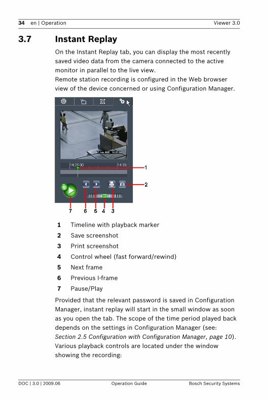
3.7 Instant ReplayOn the Instant Replay tab, you can display the most recently saved video data from the camera connected to the active monitor in parallel to the live view.Remote station recording is configured in the Web browser view of the device concerned or using Configuration Manager.
Provided that the relevant password is saved in Configuration Manager, instant replay will start in the small window as soon as you open the tab. The scope of the time period played back depends on the settings in Configuration Manager (see: Section 2.5 Configuration with Configuration Manager, page 10).Various playback controls are located under the window showing the recording:
1 Timeline with playback marker
2 Save screenshot
3 Print screenshot
4 Control wheel (fast forward/rewind)
5 Next frame
6 Previous I-frame
7 Pause/Play
Viewer 3.0 Operation | en 35
Bosch Security Systems Operation Guide DOC | 3.0 | 2009.06
TimelineThe timeline is used to navigate within the recorded data. The green playback marker indicates the time at which the image currently displayed was created. Periods for which a recording is available are displayed in light gray.
Click any point on the timeline.The playback marker jumps to the position you clicked and playback begins at this point.
The period displayed in the timescale can be changed:– You can move the period displayed by moving the mouse
along the timescale with the left mouse button held down.– You can broaden or refine the time period displayed by
placing the mouse cursor in the timescale above the timeline and scrolling (only possible if the mouse has a scroll wheel).
Further Controls
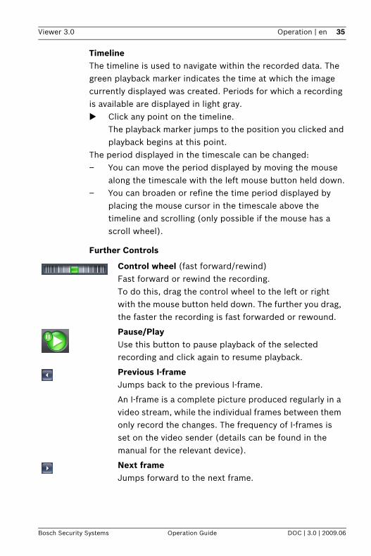
Control wheel (fast forward/rewind)Fast forward or rewind the recording.To do this, drag the control wheel to the left or right with the mouse button held down. The further you drag, the faster the recording is fast forwarded or rewound.
Pause/PlayUse this button to pause playback of the selected recording and click again to resume playback.
Previous I-frameJumps back to the previous I-frame.
An I-frame is a complete picture produced regularly in a video stream, while the individual frames between them only record the changes. The frequency of I-frames is set on the video sender (details can be found in the manual for the relevant device).
Next frameJumps forward to the next frame.

36 en | Operation Viewer 3.0
DOC | 3.0 | 2009.06 Operation Guide Bosch Security Systems
3.8 Exiting the ProgramSelect File > Exit from the main menu when you want to exit Viewer.
Save screenshotSaves a screenshot from the recording being played back in the specified folder
Print screenshotSaves a screenshot from the recording being played back and prints it on the PC's default printer

Viewer 3.0 Appendix | en 37
Bosch Security Systems Operation Guide DOC | 3.0 | 2009.06
4 AppendixTroubleshootingIf you are unable to resolve a malfunction, please contact your supplier or systems integrator, or go directly to Bosch Security Systems Customer Service.The following table is intended to help you identify the causes of malfunctions and correct them where possible.
Malfunction Possible causes Recommended solution
No connection established
Incorrect installation or configuration of Viewer
Use the Configuration Manager program to correctly integrate devices
Incorrect IP address
No additional allocation of devices possible
License expired Purchase a license for more video channels
Monitor shows screenshots instead of video
Decoding instances limited by user
Use Configuration Manager to increase the number of possible decoding instances
Camera cannot be moved
No controller selected Use Configuration Manager to select a controller for the camera you require
Camera can only be moved slowly; images transmitted with a delay
Network overloaded Decrease the number of network accesses, for example by reducing the number of possible decoding instances via Configuration Manager

38 en | Index Viewer 3.0
DOC | 3.0 | 2009.06 Operation Guide Bosch Security Systems
IndexAAdvanced (tab) 27Animation of layout change 11Archive Player 15audio function 21Audio transmission 21Auxiliary 27CCamera
allocating 20fixed position 25grouping 13iris 26
Camera control 24cursor 27
Camera list 17Camera list filter 19Camera tour 31
calling up 31creating 32duration 32editing 33
Configuration Manager 10CPU load 17DDecoding instances
maximum number 11, 19Devices
configuring 13Direction keys 25Documentation
additional 6EEncryption 13FF10 key 18F12 key 18, 23F4 key 21F9 key 17, 22Focal length 26Focus 26focus settings 26
Full screen 18full screen display 23Functions (tab) 26GGreen outline 20II-frame 35Input, digital 21Instant replay 34
time range 11Iris 26JJoystick 25LLearn (tab) 32Lens (tab) 26License 8Lip sync 11MMonitor
green outline 20red outline 20
monitor functions 22Monitor layout 22OOutput, digital 21PPanning 28Preset
accessing 25saving 26
Programexiting 18starting 8
RRecording
start 22stop 22storage location 12
Red outline 20

Viewer 3.0 Index | en 39
Bosch Security Systems Operation Guide DOC | 3.0 | 2009.06
SScreenshot 36Snapshot
storage location 12Software, version number 19Symbols 5TTilting 28Timeline 35Tour 31Triggering relay 21VVCA metadata 11Volume 17ZZoom
camera 25, 29software 30

40 en | Index Viewer 3.0
DOC | 3.0 | 2009.06 Operation Guide Bosch Security Systems


Bosch Security SystemsRobert-Koch-Straße 100D-85521 OttobrunnGermanyTelefon +49 89 6290-0Fax +49 89 6290-1020www.boschsecurity.com © Bosch Security Systems, 2009