boss room-mate user guide - ecaccesssolutions · this boss room-mate user guide is designed to...
TRANSCRIPT

BoSS Room-Mate3T - Through the Trapdoor Method
IntroductionThis BOSS ROOM-MATE User Guide is designed to provide you with step by step instructions to ensure that your system is erected with the maximum of ease and safety. Before assembly,please read this User Guide. If the scaffold is passed on to another person they should also receive these instructions.
ComplianceAll BOSS ROOM-MATE Towers must comply with the general requirements of the following:
BSEN 1004:2004 Work at Height Regulations 2005
SafetyCheck that all the components are available and are functioning
correctly.Check that the ground is level and capable of supporting the
weight of the structure.During erection it is recommended that a temporary guardrail
brace be employed.The safe working load is 275kg per platform uniformly
distributed, 750kg maximum per scaffold structure. This weight should not be exceeded.
Lifting of equipment (at higher levels)l Components should be firmly secured by a reliable lifting
material (e.g. rope) employing a reliable knot to ensure safe fastening.
MovementThe Room-Mate should only be moved by manual effort at the
base.No personnel or materials should be on the structure during
movements. During useThe BOSS ROOM-MATE is intended mainly for internal use - if
used externally, beware of winds in excess of 17mph (7.7 metres/second) and cease working on the tower.
Raising and lowering of components should be conducted within the base of the scaffold.
Beware of horizontal forces that generate in excess of 20 kg.
Preparation and InspectionInspect the equipment before use, to ensure that it is free from damage and functions properly. Ensure you are using the correct PPE equipment for the application on which you are working.
USER GUIDE
1
4 Rung Guardrail Frame
Trapdoor Platform
7-Rung Lift Frame
Locking Pin
Base Unit
Castor and Castor Adaptor or Adjustable leg
Toeboard Set
Diagonal Brace
StabiliserHorizontal Brace
Components
2

Assembly1.8m Platform Height
Insert castor into adaptor or adjustable leg and then into base of frame.
Unfold base unit, insert ocking pin, and locate deck on 2nd rung of the tower. Lock castors and level base.
Insert 2 x guardrail frames.
Move deck to 7th rung of tower.
Fit 4 x stabilisers *
Fit 4 x horizontals as guardrails (3T method) on the 9th and 11th rungs.
Fit diagonal brace (blue) on the front of the tower, from the 4th to the 8th rung.
Fit toeboards. The Tower is now complete.* Stabilisers are not required if tower is being used internally at this deck height.
2.55m Platform HeightInsert castor into adaptor
or adjustable leg and then into base of frame.
Unfold base unit, insert locking pin. Fit horizontal brace to 1st rung of open side of base unit. Lock castors and level base.
Insert deck on 2nd rung of tower.
Insert 2 x lift frames.
Fit diagonal brace (blue) on front of tower, between the 4th and 8th rungs.
Insert deck on 10th rung.
Fit 4 x stabilisers.
Fit 4 x horizontal braces (red) as guardrails (3T method) on the 12th and 14th rungs.
Fit diagonal brace (blue) on the front of the tower, betweenthe 10th and 14th rungs.
Fit toeboards.The Tower is nowcomplete.
BO
SS
RO
OM
-MAT
E Q
uant
ity S
ched
ule
Cod
e D
escr
iptio
n W
eigh
t (W
H) 2
.80m
3.
80m
4.
55m
5.
55m
6.
30m
8.
20m
(kgs
) (P
H) 0
.80m
1.
80m
2.
55m
3.
55m
4.
30m
6.
05m
No.
of r
ungs
to p
latfo
rm
3 7
10
14
17
24H
eigh
t 1
Hei
ght 2
H
eigh
t 3
Hei
ght 4
H
eigh
t 5
Hei
ght 6
3335
13
125m
m C
asto
r 2.
50
4 4
4 4
4 4
3244
13
Cas
tor A
dapt
or*
0.
21
4 4
4 4
44
*Whe
n us
ed o
n un
even
gro
und
and
adju
stm
ent i
s re
quire
d, 4
adj
usta
ble
legs
may
be
used
whi
ch re
plac
e th
e ca
stor
ada
ptor
s.30
1514
B
ase
Uni
t 21
.43
1 1
1 1
1 1
3025
14
7 R
ung
Lift
Fram
e 9.
80
2 2
4 6
3035
14
4 R
ung
Gua
rdra
il Fr
ame
5.60
2
230
4511
1.
8m T
rapd
oor D
eck
14.3
5 1
1 2
2 3
431
2513
1.
8m H
oriz
onta
l Bra
ce (r
ed)
1.88
3
4 7
9 9
1331
3513
2.
1m D
iago
nal B
race
(blu
e)
2.06
1
2 4
4
630
4514
To
eboa
rd S
et
10.0
0 1
1 1
1 1
3175
13
SP7
Fixe
d St
abili
ser
5.80
4*
4
431
8513
SP
10 A
djus
tabl
e St
abili
ser
9.87
4
4
* S
P7
Sta
bilis
er o
nly
requ
ired
whe
n R
OO
M-M
ATE
is u
sed
exte
rnal
ly.
AssemblyWhen erecting a BoSS Room-Mate:
To comply with the Work at Height Regulations, guardrails are positioned in advance of climbing onto a platform to reduce the risk of a fall.
All platforms feature double guardrails on both faces of the tower.
All guardrails should be 2 and 4 rungs (0.5m and 1.0m) above platforms.Position handrails 4 rungs above platform level.Position intermediate handrails 2 rungs above platform level.
Never stand on an unguarded platform positioned above the second rung of a tower. If your risk assessment shows it necessary you may also need to guardrail platforms at this level.
To dismantle a BoSS Room-Mate:Remove toeboards, and pass down the tower.Unclip farthest end of braces and immediately go to protected
trapdoor position on ladder to complete removal.Remove upper platforms from protected platform levels below.Pass removed components out of the tower to a colleague.
0.8m Platform HeightInsert castor into adaptor or adjustable
leg and then into base of frame.
Unfold base unit, insert locking pin. Lock castors and level base.
Insert deck on 3rd rung of tower.
Fit horizontal braces (red) as guardrails, on the 5th and 7th rungs.
The Tower is now complete.
(WH
) = W
orki
ng H
eigh
t (P
H) =
Pla
tform
Hei
ght
3
4
5
2
1
3 4
1
2
3
4
5
6
7
8
1
2
3
45
6
78
9
10
5
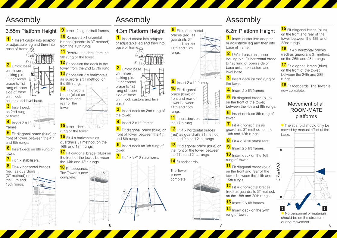
Assembly3.55m Platform Height
1 Insert castor into adaptor or adjustable leg and then into base of frame.
Unfold base unit, insert locking pin. Fit horizontal brace to 1st rung of open side of base unit., lock castors and level base.
Insert deck on 2nd rung of tower.
Insert 2 x lift frames.
Fit diagonal brace (blue) on front of tower, between the 4th and 8th rungs.
Insert deck on 9th rung of tower.
Fit 4 x stabilisers.
Fit 4 x horizontal braces (red) as guardrails (3T method) on the 11th and 13th rungs.
Insert 2 x guardrail frames.
Remove 2 x horizontal braces (guardrails 3T method) from the 13th rung.
Remove the deck from the 9th rung of the tower.
Reposition the deck in the tower, from the 2nd to 7th rung.
Reposition 2 x horizontals as guardrails 3T method, on the 9th rungs.
Fit diagonal brace (blue) on the front and rear of the tower.
Insert deck on the 14th rung of the tower.
Fit 4 x horizontals as guardrails 3T method, on the 16th and 18th rungs.
Fit diagonal brace (blue) on the front of the tower, between the 14th and 18th rungs.
Fit toeboards.The Tower is now complete.
Assembly4.3m Platform Height
Insert castor into adaptor or adjustable leg and then into base of frame.
Unfold base unit, insert locking pin. Fit horizontal brace to 1st rung of open side of base unit., lock castors and level base.
Insert deck on 2nd rung of the tower.
Insert 2 x lift frames.
Fit diagonal brace (blue) on front of tower, between the 4th and 8th rungs.
Insert deck on 9th rung of tower.
Fit 4 x SP10 stabilisers.
Fit 4 x horizontal braces (red) as guardrails 3T method, on the 11th and 13th rungs.
Insert 2 x lift frames.
Fit diagonal brace (blue) on front and rear of tower between 11th and 15th rungs.
Insert deck on the 17th rung.
Fit 4 x horizontal braces (red) as guardrails 3T method, on the 19th and 21st rungs.
Fit diagonal brace (blue) on the front of the tower, betweenthe 17th and 21st rungs.
Fit toeboards.
The Tower is now complete.
Assembly6.2m Platform Height
Insert castor into adaptor or adjustable leg and then into base of frame.
Unfold base unit, insert locking pin. Fit horizontal brace to 1st rung of open side of base unit, lock castors and level base.
Insert deck on 2nd rung of the tower.
Insert 2 x lift frames.
Fit diagonal brace (blue) on the front of the tower, between the 4th and 8th rungs.
Insert deck on 8th rung of tower.
Fit 4 x horizontals as guardrails 3T method, on the 10th and 12th rungs.
Fit 4 x SP10 stabilisers.
Insert 2 x lift frames.
Insert deck on the 16th rung of tower.
Fit diagonal brace (blue) on the front and rear of the tower, between the 11th and 15th rungs.
Fit 4 x horizontal braces (red) as guardrails 3T method, on the 18th and 20th rungs.
Insert 2 x lift frames.
Insert deck on the 24th rung of tower.
Fit diagonal brace (blue) on the front and rear of the tower, between the 18th and 22nd rungs.
Fit 4 x horizontal braces (red) as guardrails 3T method, on the 26th and 28th rungs.
Fit diagonal brace (blue) on the front of the tower, between the 24th and 28th rungs.
Fit toeboards. The Tower is now complete.
Movement of all ROOM-MATE
platformsThe scaffold should only be
moved by manual effort at the base.
No personnel or materials should be on the structure during movement.
1
2
3
4
5
6
78
910
11
12
13
14
15
16
17
18
6
1
2
3
45
6
7
8
910
11
12
13
14
7
1
2
3
45
6
7
89
11
12
1314
15
16
17
18
10
8

Checklist Inspect components prior to erection
Inspect tower prior to use
Tower upright and level
Castors locked/legs correctly adjusted
Braces and platform level
Stabilisers fitted as specified
Platforms located and windlocks on
Guardrails in place
Toeboards located
Refer to this checklist before using each time.
Product Range SGB issues the following User Guides for its product ranges.Please contact your local branch on 08705 288 388 if you would like to receive any.Alternatively, you can download them from our website, www.sgb.co.uk
BOSS GRP TowersBOSS RoommateBOSS Stairway TowersCUPLOK Scaffold System - AccessCUPLOK Scaffold System - Falsework Sup-portCUPLOK Scaffold System in use with SafetyHarnessesCOVERSPAN Temporary Roofing SystemENVIROWRAP Shrink Cladding SystemEXTRAGUARD Edge Protection SystemFencing and BarriersGASS Shoring SystemGroundworks
Hoarding PanelsLadders and StepsMobile AnchorPropsRollafloor Temporary FlooringRollaroad Temporary RoadwayROOFGUARD Edge Protection System - PermanentROOFGUARD Edge Protection System - TemporaryScaffold Tube, Fittings and Ladder BeamsScaffolding Anchors and TiesSpandeck, Stagings and Superboards
IMPORTANT INFORMATIONYou must read all relevant guides, instructions and notices prior to erecting SGB products and must comply with all warnings. SGB will not be liable for any damage to property, personal injury or any losses caused by your failure to follow the instructions contained in this guide or with other applicable notices and guidance that SGB produces.This guide is intended only for use in conjunction with SGB products.SGB reserves the right to alter products from time to time to comply with new regulations, other safety guidances or industry advancements.By mixing SGB products with other products you are risking your safety. SGB will not be liable for any loss or damage caused as a result.SGB reviews and updates its user guides from time to time in line with changes in legislation. SGB also issues safety notices on its products or packaging from time to time. These notices could affect the manner in which the products are used and you should therefore adhere to the instructions contained in these notices as well as the user guides. Where there is a conflict, most recently published instructions should prevail.Notices will be issued or published on the internet athttp://www.sgb.co.uk/updatesIf you are in receipt of an incomplete user guide or lose your user guide copies can be found at www.sgb.co.ukAll information in this User Guide is correct at the time of going to press.SGB Services Limited reserves the right to change products details or withdraw products at any time.© This brochure and its contents are the copyright of SGB Services Limited9
For further information aboutthis product or any otherproducts and services,please contact :
Youngman Group LtdThe Causeway, Maldon,Essex, CM9 4LJ,United Kingdom
t +44 (0)1621 745900f +44 (0)1621 859845e [email protected]
youngmangroup.com10