bostongear ratiotrol - literature | catalogs
TRANSCRIPT

Boston Gear®
Ratiotrol®DC Motor Speed Control
An Altra Industrial Motion Company
Beta ll SeriesSingle Phase1/6-3 HP
Installation and OperationP-3001-BG

Boston Gear® BETA ll Series P3001-BG2
Contents
Warnings . . . . . . . . . . . . . . . . . . . . . . . . . . . . .3
I General InformationIntroduction . . . . . . . . . . . . . . . . . . . . . . . . .4General Description . . . . . . . . . . . . . . . . . .4Motor Selection . . . . . . . . . . . . . . . . . . . . . .4
II InstallationInstallation Guidelines . . . . . . . . . . . . . . . . .5Installing The Controller . . . . . . . . . . . . . . .7Initial Startup . . . . . . . . . . . . . . . . . . . . . . .16
III OperationPower On/Off . . . . . . . . . . . . . . . . . . . . . .16Run . . . . . . . . . . . . . . . . . . . . . . . . . . . . . .16Stop . . . . . . . . . . . . . . . . . . . . . . . . . . . . . .16Speed Control . . . . . . . . . . . . . . . . . . . . . .17Jog . . . . . . . . . . . . . . . . . . . . . . . . . . . . . .17Reverse . . . . . . . . . . . . . . . . . . . . . . . . . . .17Inoperative Motor . . . . . . . . . . . . . . . . . . .18
IV Maintenance and RepairGeneral . . . . . . . . . . . . . . . . . . . . . . . . . . .18Adjustment Instructions . . . . . . . . . . . . . .18Troubleshooting . . . . . . . . . . . . . . . . . . . . .20
V Parts List . . . . . . . . . . . . . . . . . . . . . . . . .23
VI Ratings and SpecificationsRatings . . . . . . . . . . . . . . . . . . . . . . . . . . .23Operating Conditions . . . . . . . . . . . . . . . .24Performance Characteristics . . . . . . . . . .24Adjustments . . . . . . . . . . . . . . . . . . . . . . .24Specifications . . . . . . . . . . . . . . . . . . . . . .25
VII Drawings . . . . . . . . . . . . . . . . . . . . . . . . .26
Index . . . . . . . . . . . . . . . . . . . . . . . . . . . . . . . .28
Warranty . . . . . . . . . . . . . . . . . . . . . . . . . . . . .30
List of Tables
1 Beta II Model Matrix . . . . . . . . . . . . . . . . . .5
2 Jumper J4 Position . . . . . . . . . . . . . . . . . . .7
3 Dip Switch (SW3) . . . . . . . . . . . . . . . . . . . .8
4 Initial Potentiometer Settings . . . . . . . . . .16
5 Dynamic Braking Characteristics . . . . . . .17
6 Troubleshooting . . . . . . . . . . . . . . . . . . . . .20
7 Parts List, BETA II Controllers . . . . . . . . . .23
8 Typical Application Data . . . . . . . . . . . . . .23
9 Operating Voltages and Signals . . . . . . . .24
10 Controller Weights . . . . . . . . . . . . . . . . . . .24
11 Speed Regulation Characteristics . . . . . .24
12 Shunt Field Data . . . . . . . . . . . . . . . . . . . .25
13 Tachometer Feedback Voltage Selection .25
List of Figures
1 Controller Mounting Configurations . . . . . .9
2 Controller Mounting Dimensions . . . . . . . .9
3 Logic Connection Diagram, Run-Stop-JogSwitch . . . . . . . . . . . . . . . . . . . . . . . . . . . .10
4 Logic Connection Diagram, Forward-ReverseSwitch and Run-Stop-Jog Switch . . . . . .10
5 Logic Connection Diagram, Run-StopPushbuttons and Run-Jog Switch . . . . . .11
6 Logic Connection Diagram, Optional ArmatureContactor Reversing Using Switches . . . .11
7 Logic Connection Diagram, withUnidirectional Armature Contactor usingRun-Stop-Jog Switch . . . . . . . . . . . . . . . .11

P-3001-BG Boston Gear® BETA ll Series 3
8 Logic Connection Diagram, withUnidirectional Armature Contactor Using Run-Stop Pushbuttons & Run-Jog Switch . . . .12
9 Logic Connection Diagram, Optional ArmatureContactor Reversing UsingPushbuttons and Run-Jog Switch . . . . . .12
10 Logic Connection Diagram, Line Starting withMotor Speed Potentiometer . . . . . . . . . . .12
11 Signal Connection Diagram, Motor SpeedPotentiometer . . . . . . . . . . . . . . . . . . . . . .13
12 Signal Connection Diagram, TachometerFeedback . . . . . . . . . . . . . . . . . . . . . . . . .13
13 Signal Connection Diagram, Current (Torque)Reference Potentiometer . . . . . . . . . . . . .13
14 Signal Connection Diagram, Line Startingwithout a Motor Speed Potentiometer . . .14
15 Signal Connection Diagram, 4-20mAInterface . . . . . . . . . . . . . . . . . . . . . . . . . .14
16 Signal Connection Diagram, 4-20mATransducer with Auto/Manual Switch . . . .14
17 Signal Connection Diagram, Transducer withExternal Burden Resistor . . . . . . . . . . . . .15
18 Signal Connection, 0-10 VDC ExternalSpeed Reference . . . . . . . . . . . . . . . . . . .15
19 Functional Schematic, BETA ll Controller .26
20 Beta ll Control Board, 1/6-3 HP . . . . . . . .27
The Following SafetyPrecautions Must Be Strictly Adhered To At AllTimes.
1. You as the owner or operator of BOSTONGEAR equipment have the responsibility tohave the users of this equipment trained inits operation and warned of any potentialhazards of serious injury.
2. The drive equipment should be installed,operated, adjusted, and serviced only byqualified personnel familiar with theconstruction and operation of the equipmentand the hazards involved including thosedescribed below. Failure to observe thisprecaution can result in personal injury, lossof life, and property damage.
3. The National Electrical Code requires thatan AC line fused disconnect or circuitbreaker be provided in the AC input powerlines to the controller. This disconnect mustbe located within sight of the controller. Donot operate the controller until this coderequirement has been met.
4. The drive equipment is at AC line voltagepotential whenever AC power is connectedto the drive equipment. Contact with anelectrical conductor inside the driveequipment or AC line disconnect can causeelectric shock resulting in personal injury orloss of life.
5. Be sure all AC power is disconnected fromthe drive equipment before touching anycomponent, wiring, terminal, or electricalconnection in the drive equipment.
6. Always wear safety glasses when working onthe drive equipment.
7. Do not remove or insert circuit boards, wires,or cables while AC power is applied to thedrive equipment. Failure to observe thisprecaution can cause drive damage,personal injury, or loss of life.

Boston Gear® BETA ll Series P3001-BG4
8. All drive equipment enclosures, motorframes, and remote operator stations mustbe connected to an unbroken commonground conductor. An unbroken groundingconductor must be run from the commonground conductor to a grounding electrodeburied in the earth or attached to a plantground. Refer to the National Electrical Codeand local codes for grounding requirements.
9. The atmosphere surrounding the driveequipment must be free of combustivevapors, chemical fumes, oil vapor, andelectrically conductive or corrosivematerials.
10. Solid state devices in the controller can bedestroyed or damaged by static electricity.Therefore, personnel working near thesestatic-sensitive devices must beappropriately grounded.
Section I. General Information
Introduction
General Description
These controllers statically convert AC line powerto regulated DC for adjustable-speed armaturecontrol of shunt-wound and permanent-magnetmotors.
These controllers comply with applicablestandards established by the National ElectricalCode and NEMA for motor and industrial controlequipment. The controllers are UnderwritersLaboratories Listed (File No. E184521).
Motor Selection
These controllers control the operation ofgeneral purpose DC motors designed for use withsolid-state rectified power supplies. The motormay be shunt-wound, stabilized shunt-wound, orpermanent magnet. For maximumefficiency, the motor should be rated foroperation from a NEMA Code K power supply.

P-3001-BG Boston Gear® BETA ll Series 5
Section II - Installation
Before starting the installation, read this sectionthoroughly. In addition, a thorough review of theRatings and Specifications (Section VI) isrecommended. The following installationguidelines should be kept in mind when installingthe controller.
Installation Guidelines
1. Controller Mounting – The controller maybe mounted either vertically or horizontally.However, never mount the controller upsidedown, immediately beside or above heatgenerating equipment, or directly belowwater or steam pipes.
The controller must be mounted in a locationfree of vibration.
Table 1. BETA II Model Matrix
ItemCode
Cat.No.
Line VoltageHP Range†
Construction FunctionOperator’sControls
WiringDiagramFigure #115
VAC230VAC
AngleBracketChassis
OpenChassis
EnclosedRun/Stop
Arm.Cont.
Run/StopW/D.B.
Arm.SwitchRev.
Arm.Cont.Rev.
W/D.B.
Local(Integral)
Remote
64801 RBA2
1/6-1 1/2-2
X X 3,5
57854 RBA2C X X X 3,5
57831 RBA2U X X X 7,8
57855 RBA2CU X X X 7,8
64821 RBA2M X X X 6,9
57856 RBA2CM X X X 6,9
64805 RBA2B X X X 3,5
13048 RBA2B-WD X* X X 3,5
57852 RBA2UB X X X 7,8
13050 RBA2UB-WD X* X X 7,8
64855 RBA2MB X X X 6,9
13100 RBA2MB-WD X* X X 6,9
64814 RBA2S X X X 3
13102 RBA2S-WD X* X 3
64820 RBA2R X X X 4
13104 RBA2R-WD X* X X 4
57853 RBA2US X X X 7
13106 RBA2US-WD X* X X 7
64863 RBA2MR X X X 6
13108 RBA2MR-WD X* X X 6
64865 RBA3
1/6-1 1/2-3
X X X 3,5
57889 RBA3U X X X 7,8
64873 RBA3M X X X 7,8
* Washdown Duty† Units are reconnectable

Boston Gear® BETA ll Series P3001-BG6
Multiple controllers may be mounted side byside, as close to each other as the mountingfeet will allow.
The minimum clearance at the top andbottom of the controller may be as narrow asthe conduit fittings allow.
2. Atmosphere – The atmospheresurrounding the controller must be free ofcombustible vapors, chemical fumes, oilvapor, and electrically conductive or corrosivematerials.
The air surrounding an enclosed controllermust not exceed 40 degrees C (104 degreesF), and the air surrounding an open-chassiscontroller must not exceed 55 degrees C (131degrees F). Minimum air temperature is 0degree C (32 degrees F) for enclosed andopen-chassis controllers.
3. Controller Construction – The controllerbase is made of die-cast aluminum with apowdered epoxy finish, and the cover is madeof a die-cast aluminum alloy.
The controller enclosure is totally enclosed,nonventilated, and complies with NEMA type4 and 12 standards. There is an oil resistantsynthetic rubber gasket between the coverand base. Those models with integraloperator controls include flexible boots to sealthe switches, and a seal for the MOTORSPEED potentiometer.
4. Line Supply – The controller should not beconnected to a line supply capable ofsupplying more than 100,000 amperesshort-circuit current. Short-circuit current canbe limited by using an input supplytransformer of 50 KVA or less, or by usingcorrectly sized current limiting fuses in thesupply line ahead of the controller. Do not usea transformer with less than the minimumtransformer KVA listed in Table 8, page 23.
If rated line voltage is not available, a linetransformer will be required. If the line supplycomes directly from a transformer, place acircuit breaker or disconnect switch betweenthe transformer secondary and the controller.If power is switched in the transformerprimary, transients may be generated whichcan damage the controller. See Table 8 (page23) for minimum transformer KVA.
Do not use power factor correctioncapacitors on the supply line to the controller.
A 20-joule metal oxide varistor (MOV) isconnected across the controller terminals. Ifhigher energy transients are present on theline supply, additional transient suppressionwill be required to limit transients to 150% ofpeak line voltage.
When a 115 VAC line supply is used, connectthe white (common) wire to Terminal L2 andconnect the remaining (hot) wire to TerminalL1.
5. Isolation Transformer – While not required,an isolation transformer can provide thefollowing advantages:
a. Reduce the risk of personal injury if highvoltage drive circuits are accidentallytouched.
b. Provide a barrier to externally generatedAC supply transients. This can preventcontroller damage from abnormal lineoccurrences.
c. Reduce the potential for damagingcurrent if the motor armature, motor field,or motor wiring become grounded.
6. Grounding – Connect the green or bare(ground) wire of the line supply to the groundscrew located near the top conduit entry holein the controller base. Then ground thecontroller base by connecting the groundscrew to the earth ground. The motor frameand operator control stations must also begrounded.
Personal injury or loss of life may occur ifthe controller, motor, and operator stationsare not properly grounded.
7. Wiring Practices – The power wiring must besized to comply with the National ElectricalCode, CSA, or local codes. Refer to thecontroller data label for line and motor currentratings.
Do not use solid wire.
Signal wiring refers to wiring forpotentiometers, tachometer generators, andtransducers. Control wiring refers to wiring foroperator controls, e.g., switches and pushbut-tons. Signal and control wiring may be run in
P-3001-BG Boston Gear® BETA ll Series 7
a common conduit, but not in the same conduitas the power wiring. In an enclosure, signal andcontrol wiring must be kept separated frompower wiring and only cross at a 90 degreeangle.
If shielded wire (such a Alpha 2422 - twoconductor, 2423 - three conductor, 2424 - fourconductor) is used for the signal and controlwiring, connect the shields to chassis ground(ground screw on the controller base) and tapethe opposite ends of the shields.
Two 3/4-14 NPT threaded holes are providedfor conduit entry, one each in the top andbottom of the controller.
Installing the Controller
1. Remove the controller front cover (if used) byremoving the four cover screws.
2. Check components in the controller forshipping damage. Report shipping damage tothe carrier.
3. Check the controller and motor data labels tobe sure the units are electrically compatible.
4. Be sure the controller has been calibratedcorrectly for the motor being used. Calibrationis performed by changing the position of aJumper (J4) on the controller control board tocomply with Table 2. To change the position ofJumper J4, pull the jumper from the controlboard and then push it onto the appropriatetwo pins on the board. For the location of J4,see Figure 18 (page 15).
1. Select the position closest to the motor nameplate armaturecurrent rating.
5. Check the positions of Jumpers J1, J2 and J3on the control board. For the locations of J1,J2 and J3, see Figure 20, page 27. For a 230VAC line supply and a 180V armature motor,Jumper J1 must be in the 230Vposition, and Jumpers J2 and J3 must be inthe 180V position. For a 115 VAC line supplyand a 90V armature motor, J1 must be in the115V position, and J2 and J3 must be in the90V position. To change the position of J1, J2,or J3 pull the jumper from the control boardand then push it onto the appropriate pins onthe board.
Note: If an armature contactor card option isto be installed in the controller, do notoff-set the five-position plug (suppliedwith the card) at Connector J1 on thecontrol board. Do not confuse ConnectorJ1 with Jumper J1. Refer to the InstructionSheet supplied with the option forconnection instructions.
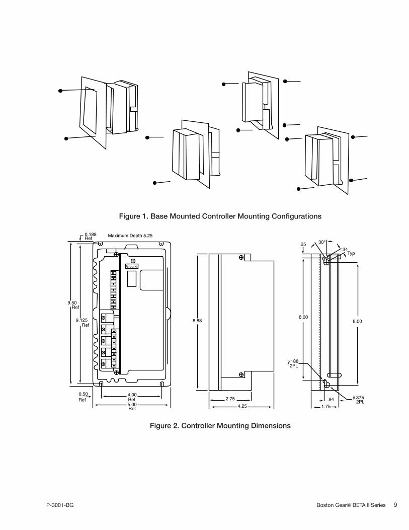
6. The controllers may be surface mounted orpanel mounted as shown in Figure 1, page 9.Mount the controller. Mounting dimensionsare shown in Figure 2, page 9.
7. Conduit entry is made by punching out theknockout at the top or bottom of thecontroller base. To prevent componentdamage from knockout fragments, applymasking tape to the inside of the knockoutbefore punching.
8. Connect the power wiring to Terminals L1, L2,A1 (+), A2 (-), F+ and F-. Be sure to observeInstallation Guidelines 4 and 7 on page 6. Ifhalf-wave shunt field voltage is desired,connect one of the motor shunt field leadsto Terminal F/2 (see Table 12 on page 25).
Note: Low inductance motors require afull-wave field to prevent currentinstability.
9. If the controller contains any options thatrequire external wiring, follow the wiringinstructions in the instruction sheet suppliedwith the option.
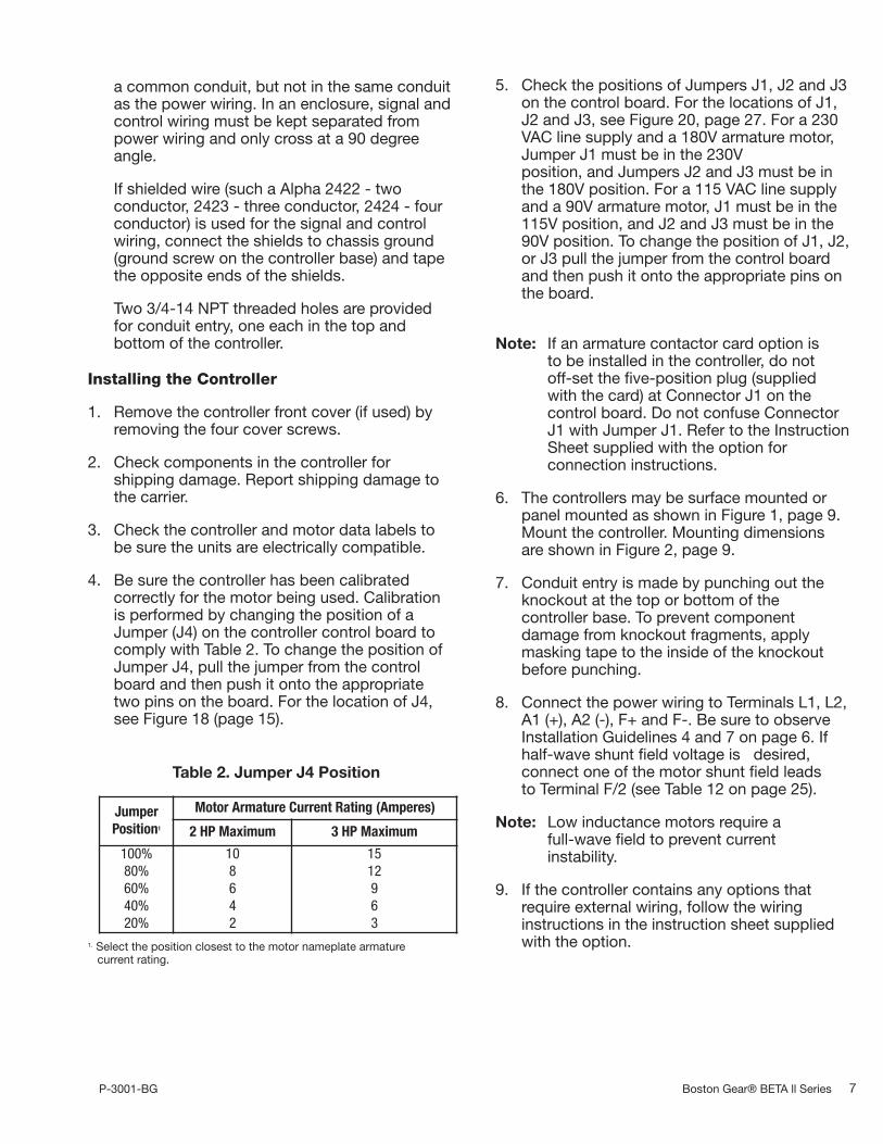
Table 2. Jumper J4 Position
JumperPosition1
Motor Armature Current Rating (Amperes)
2 HP Maximum 3 HP Maximum
100%80%60%40%20%
108642
1512963

Boston Gear® BETA ll Series P3001-BG8
10. If remote operator control wiring and/or signalwiring is required, connect the controller asshown in the appropriate connection diagram(Figures 3 through 13). Figures 3 through 10show operator control connections andFigures 11 through 18 show signalconnections.
11. The controller can be programmed for variousapplications by throwing switches on SW3.
12. Install the controller cover, if used.
Table 3. Dip Switch (SW3)
Factory Default Setting Is All Switches “ON”
Switch Position
1ONOFF
Low Voltage (3Vdc - 30Vdc) tachometer scaling.High Voltage (31Vdc - 175Vdc) tachometer scaling.
2ONOFF
Selects internal burden resistor for 4-20ma input.Selects 0 to 5V speed reference input or external burden resistor (i.e. 10 to 50ma).
3ONOFF
Selects internal current (torque) limit pot.Selects use of an external current (torque) limit pot.
4ONOFF
Selects Min Speed pot. adjustment.Selects Offset adjustment (for 4-20ma input) with Min Speed pot.
5
ON
OFF
Selects anti-restart mode. Prevents controller from restarting automatically after an AC linepower interruption.Disables anti-restart mode. Used for line starting applications (jumper TB2:9 to TB2:8 to enabledrive.
P-3001-BG Boston Gear® BETA ll Series 9
0.188Ref Maximum Depth 5.25
Ground
9.50Ref
9.125Ref
0.50Ref
Ref
4.00Ref5.00 4.25
2.75
8.88 8.008.00
.1882PL
.25 30°.34Typ
.941.75
.3752PL
ÿ
ÿ
Figure 2. Controller Mounting Dimensions
Figure 1. Base Mounted Controller Mounting Configurations

Boston Gear® BETA ll Series P3001-BG10
1
23
4
567
89
1011
SpeedAdj5K
+10V
Run
JogS1-2 -24V
Enable
TB2
115V
115V
230V
230V
J1
115/230VACL1
L2
TB1F1
E1
S1-1 Jog
RunE2
TB1A1
Armature90/180 VDC
Field100/200VFull WaveField
50/100V1/2 Wave
A2
F+
F/2
F-
180V90V
J3J2J4
CurrentScaling
100%80%60%40%20%
54321
S3
On
ÿK
ÿK
DefaultSettings
DefaultSettings
123456
89
7
+10V
Rev Run
SpeedAdj5K
1000
Fwd Jog +24VEnable
Kÿ
Kÿ
1110
TB2
S2-3 S1-2
115V
230V
230V
115V
115/230V
TB1F1
E1
S1-1 Jog
Run E2
L1
L2
TB1A1 Fwd S2-1
Rev
A2
M1
Armature90/180VDC
M2S2-2
F+
F/2
F-
J2 J3180V90V
Field50/100V1/2 Wave
Field100/200VFull Wave
J4
CurrentScaling
100%80%60%40%20%
J1
54321
On
S3
Figure 4. Logic Connection Diagram, Forward-Reverse Switch and Run-Stop-Jog Switch
Figure 3. Logic Connection Diagram, Run-Stop-Jog Switch

P-3001-BG Boston Gear® BETA ll Series 11
1234567
89
1011
SpeedAdj5K
Stop Run+24V
Enable
TB2Run
Jog
115V
115V
230V
230V
J1
115/230VAC
TB1L1
L2
F1E1 E2
TB1A1
A2
Armature90/180 VDC
F+
F/2
F-
Field50/100V1/2 Wave
Field100/200VFull Wave
180V90V
J3J2J4 100%80%60%40%20%
DefaultSettings100
0
+10V54321On
S3
Kÿ
KÿCurrentScaling
1
1
1
2
2
2
3
34 45
5
6
6
7
7
8
8
9
9
10
10
11
11
SpeedAdj5K
1000
+10V
TB2
115V
115V230V
230VJ1
L1
L2
TB1
115/230 VACF1
E1 E2
TB1A1
Reversing BoardK1K3 K1
DBK4K2
DB1
DB2K4
M1
M2
Armature90/180 VDC
Field100/200VFull WaveField
50/100V1/2 Wave
A2
F+
F/2
F-
TB6
TB5K5 K6
COM+24VRev
FwdS2Jog
RunJog
S1-1
RunDefaultSettings
S3
J4
180V90V
J2 J3
CurrentScaling
100%
60%80%
40%20%
S1-2Momentary
54321
On
KO
SpeedAdj5K Current
Scaling
DefaultSettings
180V90V
J2J1
S3J4
123456789
1011
100%80%60%40%20%
54321
TB2
230V115V
230V115V
J1
115/230VAC
TB1L1
L2
F1E1 E2
TB1A1
A2
F+
F/2
F-
Reversing Board
K1DB1
DBDB2
M2
K1
K2
M1
Armature90/180VDC
Field100/200VFull WaveField
50/100V1/2 Wave
COM+24V
123456789
1011
TB6
TB5K5
12
Run
JogRun
JogS1-1
S1-21000
+10V
On
Kÿ
Figure 5.Logic ConnectionDiagram, Run-StopPushbuttons andRun-Jog Switch
Figure 6.Logic ConnectionDiagram, OptionalArmature ContactorReversing Using
Switches
Figure 7.Logic ConnectionDiagram, withUnidirectional
Armature ContactorUsing Run-Stop-JogSwitch, 1/6-3 HP

Boston Gear® BETA ll Series P3001-BG12
SpeedAdj5K 0
100+10V
CurrentScaling
DefaultSetting
TB2 1110987654321
54321
100%80%60%40%20%
S3J4
180V90V
J3J2
230V
230V115V
115V
J1
L1L2115/230VAC
TB1F1
E1 E2
TB1A1
A2
F+
F/2
F-
Reversing BoardK1
K2
K1DB1
DBDB2
M2
M1
Armature90/180VDC
Field100/200VFull Wave
Field50/100V1/2 Wave
TB6
TB5K5
+24VCOM
1212345
Fwd
JogRun
6789
1011
Stop
Kÿ
On
SpeedAdj5K 1
234567891011
100
0
+10V
CurrentScaling
DefaultSettings
S3J454321
On
100%80%60%40%20%
180V90V
TB2
230V
230V115V
115V
J1
115/230VAC
TB1L1L2
F1E1 E2
TB1A1
A2
F+
F/2
F-
Reversing BoardK1
K1M1
M2DB2
DBDB1
K2
Armature90/180VDC
Field100/200VFull Wave
Field50/100V1/2 Wave
K5 K6TB6
TB5
121 COM
+24V234567891011
Rev
Fwd
JogRun
Stop
Kÿ
J3J2
K4
SpeedAdj5K
111098
7654321
Enable+24V
1000
+10V
TB2
115V
115V
230V
230V
115/230VAC
TB1L1
L2
F1
E1 E2
TB1A1
A2
F+
F/2
F-
Field50/100V1/2 Wave
Field100/200VFull Wave
Armature90/180VDC
180V90V
Line Starting
J3J2J4
S3
CurrentScaling
100%80%60%40%20%
54321On
J1
Kÿ
Kÿ
Figure 8.Logic ConnectionDiagram, withUnidirectional
Armature ContactorUsing Run-Stop
Pushbuttons & Run-JogSwitch 1/6-3 HP
Figure 9.Logic ConnectionDiagram, OptionalArmature ContactorReversing Using
Pushbuttons and Run-JogSwitch
Figure 10.Logic ConnectionDiagram, Line
Starting with MotorSpeed Potentiometer

P-3001-BG Boston Gear® BETA ll Series 13
SpeedAdj5K
Minimum resistance = 2KMaximum resistance = 100K
* Shielded wire recommended forlong runs or noisy environment.
* MinSpd
DefaultSettings
TB21110987654321
S3
On
54321
+10V10V
Spd Ref
S3-4
0100
0100
DC Tach50V/K
PolarityInsensitive
Note: In tach feedback mode0 and 100 ends of pot arereversed (as shown) fromIR Comp function.
TB21110987654321
One PieceJumper Tach
ArmJ6 J7J8
S3
SW3:1Default On = 3-30VDC TachShown Off = 31-175VDC
J8 NC321 100K
100K
-Arm FdbkTachArm
321
J7NC
AbsoluteValue
+ CurSignal Fdbk
J6
TachArm
321
0100
IR Comp/TachMax Spd
100K
S3-1
221K30K
On
Cur Ref5K
Spd Ref5K
100
1000
0
TB21110987654321
+10V
MinSpd5K
0100 S3-4
OffsetInput
(-)
CurLimit100K
1000 Cur Ref
S3-3
On = Internal torque limit potOff = External torque limit pot
S3
On
54321
ExternalTorque
Ref
Figure 11. Signal Connection Diagram, Motor Speed Potentiometer
Figure 12. Signal Connection Diagram, Tachometer Feedback
Figure 13. Signal Connection Diagram, Current (Torque) Reference Potentiometer

Boston Gear® BETA ll Series P3001-BG14
+10VSpeed Input
+24VEnable
Line StartS3
1110987654321
TB2
On
54321
Offset Pot50%=Normal
MinSpd Offset
InputS3-4
0100
+10V 249 ohm
S3-2
Spd Ref1-5V
InputOffset
XDCRPwr
4-20maXDCR
+-
TB2 S31110987654321
On
54321
XDCRPwr
+-
4 to 20maXDCR
Man Spd5K
1000
Auto
MinSpd
Offset Pot50%= Normal
0100 S3-4
OffsetInput
10VSpeed Ref
+10V249 ohm
S3-2
Spd Ref1-5V
InputOffset
S3TB2
Man
1110987654321
54321
On
Figure 14. Signal Connection Diagram, Line Starting without a Motor Speed Potentiometer
Figure 15. Signal Connection Diagram, 4-20 mA Interface
Figure 16. Signal Connection Diagram, 4-20 mA Transducer with Auto/Manual Switch

P-3001-BG Boston Gear® BETA ll Series 15
InputCurrent
ExternalBurden R
10-50ma4-20ma2-10ma1-5ma
100ohm 1/2W249ohm 1/4W499ohm 1/4W
1K 1/4W
XDCR+-
R= 5V1Max
*
*Use Internal 249ohm Resistor
MinSpd
OffsetInput
S3-4
0100Offset Pot
50%=Normal
+10V
Input OffsetExt Burden
S3TB2
*
1110987654321
On
54321
Spd Ref1-5V
S3-2
*249ohm
XDCRPwr
TB2
VoltageSource0-10V
+-
111098765
432
1
S3(No specific set-up)
10V Speed RefZ = 200K
Int
Figure 17. Signal Connection Diagram, Transducer with External Burden Resistor
Figure 18. Signal Connection, 0-10 VDC External Speed Reference
Boston Gear® BETA ll Series P3001-BG16
Initial Startup
1. Open the controller cover (if used) byremoving the four cover screws.
2. Be familiar with all options installed in thecontroller by reviewing the instruction sheetssupplied with the options.
3. Be sure all wiring is correct and all wiringterminations are tightened securely.
4. Be sure the controller is calibrated correctly.See steps 4 and 5 under “Installing TheController” on page 7.
5. Be sure the AC line voltage to the controlleragrees with the controller data label.
6. The potentiometers in the controller arefactory adjusted as shown in Table 4. Thesesettings will provide satisfactory operation formost applications. If different settings arerequired, refer to “Adjustment Instructions”starting on page 18.
7. If the controller has a cover, place it on thecontroller and secure it with the four coverscrews.
8. Turn-on the AC supply to the controller.
9. Check motor rotation, as follows:
a. If a MOTOR SPEED potentiometer isused, turn it fully counterclockwise. If anexternal signal is used for the speedreference, set it at minimum.
b. If a RUN-STOP-JOG switch is used, placeit in RUN position. Otherwise, initiate aRUN command.
c. Turn the MOTOR SPEED potentiometerclockwise or increase the speed referencesignal, as applicable. To stop the motor,place the switch in STOP position orinitiate a STOP command, as applicable.
If the motor rotates in the wrong direction, turn offthe AC power to the controller, and theninterchange the motor armature leads at themotor connection box or at the controllerterminal board.
10. Refer to Section III, “Operation” for operatinginstructions.
Section III - Operation
Power On/Off
To energize the drive, turn-on the AC supplyvoltage to the controller. When this occurs, themotor shunt field energizes with rated fieldvoltage, and potentially hazardous voltage ispresent at the motor armature terminals. Thesevoltages can cause electric shock resulting inpersonal injury or loss of life.
If the AC supply is interrupted and the controlleris not set up for line starting, the motor will notrestart when the AC supply is restored until thecontroller is reset by initiating a Stop commandand then a Start command. If the controller isset up for line starting and the AC supply isinterrupted, the motor will restart when the ACsupply is restored, provided the external AC linecontactor is pulled in.
Run
If a RUN-STOP-JOG switch is used, place theswitch in RUN position. Otherwise, initiate aRUN command. A RUN command will acceleratethe motor to the setting of the MOTOR SPEEDpotentiometer or external speed reference signal,as applicable. The rate of acceleration is presetby the ACCEL potentiometer on the controllercontrol board.
Stop
If a RUN-STOP-JOG switch is used, place theswitch in STOP position. Otherwise, initiate aSTOP command. A STOP command will stop themotor at a rate proportional to the stopping rateof the motor load.
Table 4. Initial Potentiometer Settings
Potentiometer Setting Description
Accel 1/3 Turn Clockwise 10 Seconds
Cur Lmt fully Clockwise (100%) 150% Load
Decel 1/3 Turn Clockwise 10 Seconds
IR/Tach Fully Counterclockwise (0%) 0% Boost
Max Spd 3/4 Turn Clockwise 100% Speed
Min Spd Fully Counterclockwise (0%) 0% Speed

P-3001-BG Boston Gear® BETA ll Series 17
If the controller has dynamic braking, the motorstopping time will be reduced. Dynamic brakingprovides exponential rate braking of the motorarmature, which occurs when the circuit isopened between the controller and the motorarmature, and one or more resistors areconnected across the motor armature.
The dynamic braking resistors provide initialbraking torque and stops per minute as shownin Table 5.
An antiplug feature is included with ArmatureContactor Reversing With Dynamic Braking. Thisfeature prevents restarting the motor before themotor has braked to a stop.
Speed Control
Motor speed is directly proportional to the settingof the MOTOR SPEED potentiometer or themagnitude of an external speed reference signal,as applicable. This potentiometer or the speedreference signal may be adjusted while the motoris running or may be preset before the motor isstarted.
The rates of acceleration and deceleration arepreset by the ACCEL and DECEL potentiometers,respectively, located on the controller controlboard.
Maximum speed and minimum speed are presetby the MAX SPD and MIN SPD potentiometers,respectively, located on the control board.
Jog
If a RUN-STOP-JOG switch is used, place theswitch in JOG position. Otherwise initiate a JOGcommand. Jog is momentary, causing motorrotation only while the switch is held in JOGposition or while a JOG command is active.Release the switch to stop the motor.
Normally, jog speed is directly proportional to thesetting of the MOTOR SPEED potentiometer. If aseparate JOG SPEED potentiometer is used, jogspeed will be directly proportional to the settingof the JOG SPEED potentiometer.
Reverse
To reverse motor rotation on controllers withreversing capabilities, initiate a STOP functionand then initiate a reversing command. The motorwill then accelerate to the setting of the MOTORSPEED potentiometer or external speed referencesignal, as applicable. Forward and reverse speedranges are identical.
If a FWD-REV switch is used, it must have acenter position interlock, which requires amomentary relaxation of pressure before theopposite position can be engaged. The centerposition causes a STOP command and allowstime for the motor to stop before a REVERSEcommand is initiated. If a REVERSE command isinitiated while the motor is rotating, motor andcontroller damage may occur.
Table 5. Dynamic Braking Characteristics1
Component ModelRatedVoltage
Rated Horsepower
1/6 1/4 1/3 1/2 3/4 1 1-1/2 2 3
BrakingTorque (%)
RBA2M115V 180 129 103 66 44 34 N/A N/A N/A
230V N/A N/A 400 278 190 130 88 62 N/A
RBA3M115V 300 215 170 110 75 60 N/A N/A N/A
230V N/A N/A N/A 400 320 220 145 105 85
StopsPer Minute
RBA2M115V 15 12 11 8 6 2 N/A N/A N/A
230V N/A N/A 12 8 6 1 1 1 N/A
RBA3M115V 9 6 5 5 4 4 N/A N/A N/A
230V N/A N/A N/A 5 4 4 3 3 2
1. High Inertia Loads may extend braking time and cause the wattage rating of the dynamic braking resistors to be exceeded.

Boston Gear® BETA ll Series P3001-BG18
If Armature Contactor Reversing With DynamicBraking is installed, an antiplug feature preventsreversing the motor before the motor hasstopped.
Inoperative Motor
If the motor stops and/or won’t start, turn off theAC supply to the controller, remove the controllercover (if used), and check the AC line fuse on thecontroller control board. For the location of thefuse, see Figure 20, page 27. If the fuse is blown,refer to the Troubleshooting Table (Table 6).
Section IV - Maintenance and Repair
General
1. Keep the controller dry and free of dust, dirt,and debris. No parts require periodicreplacement.
2. Periodically turn off the AC line supply to thecontroller and check wire terminations to besure they are tight.
3. Visually check components for damage dueto overheating or breakage. All damagedand/or faulty components must be replacedfor satisfactory operation.
4. Maintain the motor according to maintenanceinstructions supplied by the motormanufacturer.
Adjustment Instructions
Acceleration
1. Set the MOTOR SPEED potentiometer at100% or the external speed reference signalat maximum, as applicable.
2. Initiate a RUN command and observe the timerequired for the motor to reachmaximum speed.
3. Adjust the ACCEL potentiometer for thedesired rate. Full counter clockwise rotation isthe fastest acceleration (0.1 second), and fullclockwise rotation is the slowest acceleration(30 seconds).
Deceleration
1. With the motor running at maximum speed,quickly reset the MOTOR SPEED potentio-meter to zero, or quickly decrease the speedreference signal to minimum, as applicable,and observe the time required for the motorto reach minimum speed.
2. Adjust the DECEL potentiometer for thedesired rate. Full counter clockwise rotationis the fastest deceleration (0.1 second), andfull clockwise rotation is the slowestdeceleration (30 seconds).
IR Compensation
IR compensation is used only for armaturefeedback. The IR/COMP potentiometer isfactory set at zero (full counterclockwise rotation)for satisfactory operation with most motors. Ifimproved speed regulation is desired, readjustIR compensation as follows:
1. If the motor is shunt-wound, run it at ratedbase speed. If the motor is a permanent-magnet type, run it at about 1/3 speed.
2. Turn the IR/COMP potentiometer clockwiseslowly until motor speed becomes unstable.Then turn the potentiometer counterclockwiseuntil motor speed stabilizes.
Maximum Speed
The MAX SPD potentiometer is factory set toprovide 90 VDC armature voltage with a 115 VACline, or 180 VDC armature voltage with a 230 VACline.
To readjust maximum speed, run the motor atmaximum speed and adjust the MAX SPDpotentiometer for the desired maximum speed.
Note: If the MAX SPD potentiometer is turnedtoo far counterclockwise, speed instabilitymay occur.
Minimum Speed
1. Turn the MIN SPD potentiometer fullycounterclockwise (0%) for zero speed.

P-3001-BG Boston Gear® BETA ll Series 19
2. Set the MOTOR SPEED potentiometer at 0%.
3. Initiate a RUN command and adjust the MINSPD potentiometer for the desired minimumspeed (adjustable from 0 to 40% of motorbase speed).
Current Limit
1. Turn the CUR LMT potentiometer fullyclockwise (100%) to limit motor armaturecurrent to 150% of rated.
2. Turn the CUR LMT potentiometercounterclockwise to reduce maximum motorarmature current.
Note: An external 5K ohm Current (Torque)Limit potentiometer can be used asshown in Figure 13 on page 13. Dipswitch S3 position 3 must be in the OFFposition if an external Current (Torque)Limit potentiometer is desired.
3. The GREEN power on LED indicator willchange to RED whenever the controller islimiting (or regulating) current to the motor.
Tachometer Feedback Setup
1. Before connecting or configuring tachometerfeedback, follow the instructions to install andperform initial startup, then run drive withmaximum input speed reference and adjustthe MAX SPEED potentiometer (R8b) for thedesired maximum motor speed. Note that forbest performance, this should be within ±20%of the motor nameplate maximum speed orstability problems may occur.
2. Move the one piece jumper on J6, J7 and J8from the ARM position to the TACH position.
3. Select the tachometer voltage scaling at maxspeed by dip switch SW3:1 as follows:
TACH VOLTS SW3:18 to 30Vdc ON
31 to 175Vdc OFF
4. Adjust the IR/TACH MAX SPEED potentio-meter fully clockwise, this will provideminimum speed with tach feedback.
5. Run the motor with maximum speedreference and start adjusting the IR/TACHMAX SPEED potentiometer counterclockwiseuntil motor speed increases to the desiredmaximum speed with tach feedback. Notethat if the tachometer signal is lost, the drivewill automatically revert back to armaturefeedback.

Boston Gear® BETA ll Series P3001-BG20
Troubleshooting
The following table is provided as a guide to common problems that may occur with a DC motorcontroller and the corrective action that may resolve that problem.
Table 6. Troubleshooting
Indication Possible Cause Corrective Action
1. Motor won’t start (See“Inoperative Motor” Page 18).
AC line openBe sure rated AC line voltage is applied to thecontroller.
Operator controls inoperative or connectedincorrectly
Repair accordingly.
Open circuit between Connectors E1 and E2. A wire jumper or switch must connect E1 to E2.
Controller not resetInitiate a STOP command and then a STARTcommand.
Line Voltage Selection Jumper J1 in wrong positionSee Step 5 on Page 7 under, “Installing TheController.”
Controller not enabled Be sure +24 VDC is applied to Terminal TB2-8.
Loss of speed reference signal Check for 0 - 10 VDC speed reference signal.
Controller not adjusted correctlyTurn the ACCEL and CUR LIM potentiometers fullycounterclockwise (100%).
Open shunt field winding or wiring to the motorshunt field, causing loss of torque1
Check the motor shunt field and associated circuitryfor a loose connection or a broken wire. Repairaccordingly.
Motor failure Repair or replace the motor.
Control board failure Replace the control board.
2. Controller line fuse blowswhen AC line power is appliedto the controller.
Wiring faulty or incorrectCheck all external wiring terminating in thecontroller. Correct accordingly.
Circuit, component, or wiring grounded Remove ground fault.
SCR 1, SCR 2, SCR 3, or SCR 4 shorted Replace shorted SCR’s or the control board.
Bridge diode D1b shorted Replace shorted diode or the control board.
Varistor RV1 shorted Replace RV1 or the control board.
Shunt field diode D39, D40, D41 or D42 shorted1 Replace shorted diode or the control board.
Motor shunt field shorted or grounded1 Repair or replace the motor.
Control board failure Replace the control board.
3. Controller line fuse blowswhen a START command isinitiated.
One or more SCR’s or Diode D1b shorted Replace shorted devices or the control board.
Motor shorted or grounded Repair or replace the motor.
Control board failure causing SCR’s to turn-on fully Replace the control board.
(continued)
(1) Does not apply to permanent-magnet motors.

Troubleshooting
Table 6. Troubleshooting (continued)
Indication Possible Cause Corrective Action
4. Controller line fuseblows while the motor isrunning.
Motor overloaded
Check shunt field current 1. Low shunt field current causesexcessive armature current. If field current is adequate, check for amechanical overload. If the unloaded motor shaft does not rotatefreely, check motor bearings. Also check for a shorted motorarmature. Motor overload can also be caused by incorrect gear ratio.Correct accordingly.
Loose or corroded connection. Wiring faulty,incorrect, or grounded
Check all terminals, connections, and wiring between the line,controller, and motor.
Motor shorted or grounded Repair or replace the motor.
One or more SCR’s or Diode D1bbreaking down (shorting intermittently)
Replace faulty devices or the control board.
Control Board Failure causing SCR falsefiring or misfiring
Replace the control board.
5. Minimum speedexcessive
Minimum speed not adjusted correctly Turn the MIN SPD potentiometer counterclockwise.
Motor armature grounded Correct ground fault.
Control board failure Replace the control board.
6. Maximum speedexcessive
Maximum speed set too high Turn the MAX SPD potentiometer counterclockwise.
Controller not calibrated correctly Refer to Steps 4 and 5 on page 7.
Open shunt field winding or wiring to themotor shunt field 1
Check the motor shunt field and associated circuitry for a looseconnection or a broken wire. Repair accordingly.
Motor field demagnetized 2 Replace the motor.
7. Motor won’t reach topspeed.
Low line voltage Check for rated line voltage, ±10%, on the controller line terminals.
Motor overloaded
Check shunt field current 1. Low shunt field current causesexcessive armature current. If field current is adequate, check for amechanical overload. If the unloaded motor shaft does not rotatefreely, check motor bearings. Also check for a shorted motorarmature. Motor overload can also be caused by incorrect gear ratio.Correct accordingly.
Maximum speed set too low Turn the MAX SPD potentiometer clockwise.
Current limit set too low Turn the CUR LMT potentiometer clockwise.
Current scaling jumper J4 in wrong position See Step 4 and Table 2 (page 7).
Motor field demagnetized 2 Replace the motor.
Control board failure Replace the control board.
P-3001-BG Boston Gear® BETA ll Series 21
(continued)
(1) Does not apply to permanent-magnet motors. (2) Does not apply to shunt-wound motors.

Boston Gear® BETA ll Series P3001-BG22
Troubleshooting
Table 6. Troubleshooting (continued)
Indication Possible Cause Corrective Action
8. Unstable speed
AC line voltage fluctuatingObserve line voltage with a voltmeter or oscilloscope. If fluctuationsoccur, correct condition accordingly.
Loose or corroded connection. Wiringfaulty, incorrect, or grounded
Check all terminals, connections, and wiring between the line,operator controls, controller, and motor.
Oscillating load connected to themotor
Stabilize the load. Turning the IR/TACH potentiometer counterclockwisemay minimize oscillation.
Voltage selection jumpers J1, J2 or J3in wrong position
See Step 5 on page 7 under “Installing The Controller.”
IR compensation not adjustedcorrectly
See the IR Compensation adjustment instructions on page 18.
Maximum speed not adjustedcorrectly
See the Maximum Speed adjustment instructions on page 18.
Motor faulty Check motor brushes. Replace if needed. Repair or replace the motor.
Tachometer generator or couplingfaulty (if used)
Repair accordingly.
9. Line and motor armaturecurrent excessive
Motor overloaded
Check shunt field current 1. Low shunt field current causes excessivearmature current. If field current is adequate, check for a mechanicaloverload. If the unloaded motor shaft does not rotate freely, checkmotor bearings. Also check for a shorted motor armature. Motor over-load can also be caused by incorrect gear ratio. Correct accordingly.
10. Shunt field current 1 toolow
Open shunt field winding or wiring tothe motor shunt field
Check the motor shunt field and associated circuitry for a looseconnection or a broken wire. Repair accordingly.
Shunt field connected for incorrectvoltage
Check motor rating and refer to Table 12, page 25.
Diode D39, D40, D41 or D42 failure Replace faulty diode or the control board.
11. Shunt field current 1 toohigh
Shunt field connected for incorrectvoltage
Check motor rating and refer to Table 12, page 25.
Shunt field windings shortedMeasure the shunt field resistance and compare with the motorrating. Repair or replace the motor.
12. Motor thermal guardtripped (if used)
Ventilation insufficient Remove dirt, dust, and debris from motor intake and exhaust screens.
Excessive motor load at low speed Reduce the load or increase the speed.
Line and motor armature currentexcessive
See Indication 9.
Motor overheating from friction Check for misalignment. Realign the motor.
Shorted motor windings or faultybearings
Repair or replace the motor.
(1) Does not apply to permanent-magnet motors. (2) Does not apply to shunt-wound motors.

P-3001-BG Boston Gear® BETA ll Series 23
Section VI - Ratings and Specifications
Ratings
1. Duty . . . . . . . . . . . . . . . . . . . . . . .Continuous
2. Horsepower Range. . . . . . . . . . .1/6 - HP (See Table 1, Page 5)
3. Line Fuse Interrupting Capacity. . . . . . . . . . . . . . . . . . . . .100,000 Amperes
4. Line Power. . .115V or 230V, Single-Phase, 50 or 60 Hz
5. Motor Speed Potentiometer. . . . . . . . . . . . . . . . . . . . . . .5K Ohms, 1/2W
6. Overload Capacity, Armature Circuit. . . . . . . . . . . . . . . . . . . . .150% for 1 Minute
7. Timed Overload Threshold . . . . . . . . .120%
8. Service Factor . . . . . . . . . . . . . . . . . . . . .1.0
Part RatingPart Number
Model RBA2 Model RBA3
Control Board N/A 89301 89302
Diode D1b15a, 600v 64989 N/A
24a, 600v N/A 64990
Fuse, Line, F1 30A, 600v (ATM-30) 64991 64991
SCR1, SCR2, SCR3, SCR415A, 600V 64993 N/A
55A, 800V N/A 64994
Table 7. Parts List, Beta II Controllers
Section V - Parts List
Component Ratings
Rated Horsepower (HP) 1/6 1/4 1/3 1/2 3/4 1 1-1/2 2 3
Rated Kilowatts (kW) 0.124 0.187 0.249 0.373 0.560 0.746 1.120 1.492 2.238
1-PhaseAC Input(Full-Load)
Line Amps
115VUnit
3.9 5.0 6.0 8.7 12.4 15.8 - - -
230VUnit
- - - 4.2 5.9 8.8 12.6 15.8 22.0
KVA 0.48 0.58 0.71 1.00 1.40 2.00 3.00 4.00 5.00
DC Output(Full-Load)
MotorArmatureAmps
90 V 2.0 2.8 3.5 5.4 8.1 10.5 - - -
180V - - - 2.6 3.8 5.5 8.2 11.6 15.1
Motor FieldAmps
(Maximum)
RBA2Model
1.0 1.0 1.0 1.0 1.0 1.0 1.0 1.0 -
RBA3Model
1.5 1.5 1.5 1.5 1.5 1.5 1.5 1.5 1.5
Full-Load Torque (lb-ft) with1750 RPM Base Speed Motors
0.5 0.75 1.0 1.5 2.2 3.0 4.5 6.0 9.0
Minimum Transformer KVA ForVoltage Matching or Isolation
0.5 0.75 0.75 1.0 1.5 2.0 3.0 5.0 7.5
Table 8. Typical Application Data

Boston Gear® BETA ll Series P3001-BG24
Ratings (continued)
Table 9. Operating Voltages and Signals
Operating Conditions
1. Altitude, Standard. . . . . .1000 Meters (3300 Feet) Maximum (1)
2. Ambient Temperature. . . . . . . . . . . . . . . . .0-40°C (32°F - 104°F) (2)
3. Line Frequency Variation . . . .±2 Hz of Rated
4. Line Voltage Variation . . . . . . . .±10 of Rated
5. Relative Humidity . . . . .95% Noncondensing
(1) Controller can be derated by 1% per 100 meters to operateat higher altitudes.
(2) 55°C (131°F) maximum in enclosed areas where open-chassiscontrollers are mounted.
Performance Characteristics
1. Controlled Speed Range. . . . . . . . . . . . . . . . .0 to Motor Base Speed
2. Efficiency (Rated Speed/Rated Load) . .87%
a. Controller Only . . . . . . . . . . . . . . . . . .98%b. Controller with Motor, Typical . . . . . . .85%
3. Speed Regulation . .Regulation percentagesare of motor base speed under steady-stateconditions.
Adjustments
1. Acceleration, Linear . . . . . .0.1 - 30 Seconds
2. Deceleration, Linear . . . . . .0.1 - 30 Seconds
3. IR (Load) Compensation . . . .0 to 10% Boost
4. Jog Speed. . . . . . . . . . .0 - 100% of Motor Base Speed
5. Maximum Speed. . . . . . . .50% - 100% of Motor Base Speed
6. Minimum Speed. . . . . . . . . . . .0 - 40% of Motor Base Speed
7. Torque (Current) Limit. . . . . . . . . . . .0 - 150% of Full-Load Torque
PowerSource(Singlephase)
Output VDC Speed Ref-erenceSignal
MagneticControlVoltageArmature Field
115V, 50 or60 Hz
0-90 50/1000-10 VDC 24 VDC
230V, 50 or60 Hz
0-180 100/200
Table 10. Controller Weights
Controller Model Weight - LBS (KG)
RBA2C 0.9 (0.41)
RBA2CU, RBA2CM 1.7 (0.77)
RBA2, RBA3 3.25 (1.48)
RBA2U, RBA2MRBA3U, RBA3M
3.8 (1.75)
RBA2B, BRA2B-WDRBA2S, RBA2S-WDRBA2R, RBA2R-WD
5.5 (2.50)
RBA2UB, RBA2UB-WDRBA2US, RBA2US-WDRBA2MB, RBA2MB-WDRBA2MR, RBA2MR-WD
6.05 (2.74)
Table 11. Speed Regulation Characteristics
RegulationMethod
Variable
Load Change(95%)
Line voltage(±10%)
Field Heating(Cold/Normal)
Temperature(±10°C)
SpeedRange
Standard Voltage Feedbackwith IR Compensation
2% ±1% 5 - 12% ±2% 50:1
DC Tach Feedback 0.5% ±1% 0.2% ±2% 200:1
P-3001-BG Boston Gear® BETA ll Series 25
Specifications
1. AC Line Protection - A 100,000 ampereinterrupting capacity AC line fuse providesinstantaneous protection from peak loadsand fault currents. This line fuse is locatedinside the controller.
2. Auxiliary Contact - A normally-open Form Arelay contact, rated .5 ampere at 115 VACand 2A at 30 VDC, is available for externaluse. The relay energizes when a RUNcommand is initiated, and de-energizeswhen a Normal STOP command is initiated,the overload monitor trips, or the anti-restartcircuit is activated.
3. Field Supply - A half-wave or full-wave shuntfield supply is available as Shown in Table 12.
Table 12. Shunt Field Data
1 Low inductance motors require a full-wave field to prevent speedinstability.
4. Motor Contactor - Controller model numberswith an ‘M’ or ‘U’ in the suffix, e.g., RBA2U,RBA2M, have a DC magnetic armaturecontactor which disconnects both motorarmature leads from the controller. An antiplugcircuit ensures that the contactor does notmake or break DC.
5. Power Conversion - The DC power bridgeconsists of four SCR’s and one freewheelingdiode. Each device is rated at least 600 PIV.The controller base forms an integral heat sinkwith the power devices electricallyisolated from the base.
6. Selectable Capabilities - Switches allow theuser to select various modes of operation asfollows:
a. Line Starting - By placing SW3:5 in theOFF position, the ‘anti-restart’ feature willbe disabled, and the controller may bestarted and stopped with an external ACline contactor. However, a wire jumpermust be connected between TB-2-8 andTB2-9. If full speed operation is desired,connect another wire jumper betweenTB2-2 and TB2-3.
b. Tachometer Feedback - To usetachometer feedback with armaturefeed-back backup, connect thetachometer generator signal to TB2-7 andTB2-5 (polarity insensitive) and select thetachometer generator voltage atmaximum speed by using SW3:1 asfollows:
Table 13. Tachometer Feedback VoltageSelection
c. Torque Regulator - The controller willfunction as a torque regulator whenSW3:3 is OFF. This allows an externalpotentiometer to set maximum motortorque (0 - 150% of rated).
7. Voltage Transient Protection - A metal oxidesuppressor (varistor) across the AC line iscombined with RC snubbers across thepower bridge to limit potentially damaginghigh voltage spikes from the AC powersource.
ControllerRating(VAC)
Shunt Field Voltage (VDC)Motor Shunt FieldLead Connections
Half-Wave Full-Wave 1 F1 F2
11550 F/2 F-
100 F+ F-
230100 F/2 F-
200 F+ F-
Tach Voltage SW3:1
8Vdc - 30Vdc ON
31Vdc - 175Vdc OFF

Boston Gear® BETA ll Series P3001-BG26
=Po
werC
onne
ction
TB1
=Cu
stom
erIn
terfa
ceTB
2=
Optio
nCo
nnec
torJ
5=
Spac
eCo
nnec
tor(
noto
n5
HPVe
r)
Line
Volta
geSe
lectio
nJ1
230V
115V
230V
115V
AC1
AC2
8VAC
20VA
C
20VA
C
2 6
+10V
10V
2K78
12
7912
91184
+12V
-12V
47/
5010
0V50
-24V
+24V
Grn=
OnRe
d=Cu
rrent
Limit
U2D32
4
Curre
ntRe
g
Open
for
Line
Star
t
S3-5
Anti
Resta
rt
Load
Mon
itor
12Rese
t
Supe
rviso
ryLo
gic
Q8
KOKO
Enab
le
11108
Run
Coas
tSt
op
9541236
+24V
0
100
+10VSpd
Ref
5K10
0 0+10V
+10V
4-20
MA
1
10
S3-2
Open
For
Ext
Burd
enRe
s
249
150K
324
U1B
80K
200K
Open
For
Offse
tS3
-40
100
Min
Spd
5KOp
enFo
rTo
rue
Inpu
tS
3-3 10
0 0
Curre
ntLim
it10
0K
500K
150K
Offst
Inpu
t
150K
1K
1M15
0K
2M Dece
l
0
100
0
100
2M Acce
l
U3B
324
100K
100K
FL-1
V
Curre
ntSi
gnal
9VAC
-12V
22M
100K
100K
100K
13
--
++
324
- +
Abso
lute
Value
Tach
Arm
010
0IR
Conp
/M
axSp
dTa
ch
221K
30K
7Op
enfo
rHV
TachS3-1
J7Ar
m
Tach
J6,7
,8Se
tBy
One
Piec
eJu
mpe
rJ65
7
200K 1uf
324
- +U2
B
80K
Max
Spd
Arm
Tach Arm
Arm
Back
up
Arm
Isolat
or89
K
324
- +10
KM
axSp
d
6.2K
2M 2M89
K2M2M
J2
J3 180V
90V
180V
90V
R5Sh
unt
Isolat
or10
0% 80%
60%
40%
20%
TB1A290
/180
VDCA1
6TB
1R3
FL=
100M
V2H
P=.0
1Ω
SCR2
SCR1
SCR3
SCR4
E2E1 AC
2S1-A
AC1
F1 ATM
-30
TB1
110/
230V
ACL1
1 2 3 4 5
L2 F+ F-F/2
110/
200V
50/1
00V
Com
Field
Conn
ectio
ns
G1&
2
G3 G4
Cont
rol
And
Firin
gCi
rcuit
Erro
rSi
gnal
Spee
dRe
g U3C32
4- +
150K3
324 +-
+22uf
C5
ExtA
ccel
Cap
Figure 19. Functional Schematic, BETA II Controller
Section VII - Drawings

P-3001-BG Boston Gear® BETA ll Series 27
5 Position Dip Switch(All set in closed position) Calibration Pot
Armature-TachFeedback3 PositionJumper J6, J7,J8 (set onArmature)
MotorCurrentJumper J4Set @ 100%
90/180V ACJumpers J2 & J3(Shown in 180VPosition)
115/230V ACJumper J1(Shown in 230VPosition)
AC Line Fuse F1
Connector E1
Connector E2Shunt Resistors
Motor ArmatureConnectionTerminals
Motor Shunt FieldConnectionTerminals
AC LineConnectionTerminals
Logic & SignalConnectionTerminals
Bi-Color LEDGreen = Power OnRed = Current Limit
IR/Tachometer
Current Limit Pot
Minimum Speed Pot
Maximum Speed Pot
Option Connector J5Acceleration Pot
Deceleration Pot
Line StMin/OffSpd/TrqBurdenTach V
A2-
A1+
F-F/
2F+
L2L1
1110
98
76
54
32
1
TB1
TB2
F1
R3B
R4B
E1E2SC
R1SC
R2D1
BSC
R2SC
R4
115V
J123
0V
54
32
1
180V
J3
90V
180V
J2
J410
0%80
%60
%40
%20
%90V
Arm Tach
J8J7
J8 TP1 G R
RECu
rLm
tCu
rLm
tIR
/Ta
chR8B
R11B
Min
Spd
Max
Spd
Acce
lDec
el J5 1
R7B
R8B
R10B
TP3
R12B
TP6
R5B
Cont
rolB
oard
1067
039_
-DC1
Rev_
TP2T
P4
TP8
TP18
Figure 20. BETA II Control Board, 1/6 - 3 HP

Boston Gear® BETA ll Series P3001-BG28
AAC Line Protection . . . . . . . . . . . . . . . . . . . . .25AC Supply Transients . . . . . . . . . . . . . . . . . . . .6ACCEL Potentiometer . . . . . . . . . . . . . . . . . . .18Acceleration, Linear . . . . . . . . . . . . . . . . . . . . .24Altitude, Standard . . . . . . . . . . . . . . . . . . . . . .24Ambient Temperature . . . . . . . . . . . . . . . . . . .24Antiplug Circuit . . . . . . . . . . . . . . . . . . . . . . . .25Antiplug Feature . . . . . . . . . . . . . . . . . . . . . . .17Anti-Restart Feature . . . . . . . . . . . . . . . . . . . . .8Armature Feedback Backup . . . . . . . . . . . . . .19Atmosphere . . . . . . . . . . . . . . . . . . . . . . . . . . . .6Auxiliary Contact . . . . . . . . . . . . . . . . . . . . . . .25
CCircuit Breaker . . . . . . . . . . . . . . . . . . . . . . . . . .6Conduit Entry . . . . . . . . . . . . . . . . . . . . . . . . . .7Control Wiring . . . . . . . . . . . . . . . . . . . . . . . . . .6Controlled Speed Range . . . . . . . . . . . . . . . . .24Controller Construction . . . . . . . . . . . . . . . . . . .6Controller Mounting . . . . . . . . . . . . . . . . . . . . .5CSA . . . . . . . . . . . . . . . . . . . . . . . . . . . . . . . . .6Current Limit Potentiometer . . . . . . . . . . . . . .19Current (Torque) Limit Potentiometer . . . . . . .19Current (Torque) Reference Potentiometer . . .16Current Limit . . . . . . . . . . . . . . . . . . . . . . . . . .19Current Limiting Fuses . . . . . . . . . . . . . . . . . . .6
DDecel Potentiometer . . . . . . . . . . . . . . . . . . . .18Deceleration, Linear . . . . . . . . . . . . . . . . . . . .24Disconnect Switch . . . . . . . . . . . . . . . . . . . . . .6Displacement Power Factor (Rated
Speed/Rated Load) . . . . . . . . . . . . . . . . . .23Duty . . . . . . . . . . . . . . . . . . . . . . . . . . . . . . . . .23Dynamic Braking . . . . . . . . . . . . . . . . . . . . . . .17Dynamic Braking Resistors . . . . . . . . . . . . . . .17
EEfficiency (Rated Speed/Rated Load) . . . . . . .24Electrical Noise . . . . . . . . . . . . . . . . . . . . . . . . .7
FField Supply . . . . . . . . . . . . . . . . . . . . . . . . . .25Full-Wave Field . . . . . . . . . . . . . . . . . . . . . . . .25Fuses . . . . . . . . . . . . . . . . . . . . . . . . . . . . . . . . .6
GGround Screw . . . . . . . . . . . . . . . . . . . . . . . . . .6Grounding . . . . . . . . . . . . . . . . . . . . . . . . . . . . .6
HHalf-Wave Shunt Field Voltage . . . . . . . . . . . .25Horsepower Range . . . . . . . . . . . . . . . . . . . . .23
IIR (Load) Compensation . . . . . . . . . . . . . . . . .24IR/Comp Potentiometer . . . . . . . . . . . . . . . . .18Isolation Transformer . . . . . . . . . . . . . . . . . . . . .6
JJog Speed . . . . . . . . . . . . . . . . . . . . . . . . . . . .24Jog Speed Potentiometer . . . . . . . . . . . . . . . .17Jumper J1, J2, J3 and J4 . . . . . . . . . . . . . . . . .7
LLine Frequency Variation . . . . . . . . . . . . . . . . .24Line Fuse . . . . . . . . . . . . . . . . . . . . . . . . . . . . .25Line Fuse Interrupting Capacity . . . . . . . . . . .23Line Power . . . . . . . . . . . . . . . . . . . . . . . . . . .23Line Starting . . . . . . . . . . . . . . . . . . . . . 7, 14, 25Line Supply . . . . . . . . . . . . . . . . . . . . . . . . . . . .6Line Voltage Variation . . . . . . . . . . . . . . . . . . .24Low Inductance Motors . . . . . . . . . . . . . . . . . .7
MMax Spd Potentiometer . . . . . . . . . . . . . . . . .19Maximum Speed . . . . . . . . . . . . . . . . . . . .18, 24Min Spd Potentiometer . . . . . . . . . . . . . . . . . .19Minimum Speed . . . . . . . . . . . . . . . . . . . .18, 24Minimum Transformer KVA . . . . . . . . . . . . . . . .6Motor Contactor . . . . . . . . . . . . . . . . . . . . . . .25Motor Rotation . . . . . . . . . . . . . . . . . . . . . . . .16Motor Speed Potentiometer . . . . . . . . . . . . . .16
NNational Electrical Code . . . . . . . . . . . . . . . .4, 6NEMA . . . . . . . . . . . . . . . . . . . . . . . . . . . . . . .4NEMA Type 4 and 12 Standards . . . . . . . . . . . .6
OOscillating Load . . . . . . . . . . . . . . . . . . . . . . .22Overload Capacity, Armature Circuit . . . . . . . .23
PPower Bridge . . . . . . . . . . . . . . . . . . . . . . . . . .25Power Conversion . . . . . . . . . . . . . . . . . . . . . .25Power Factor Correction Capacitors . . . . . . . .6Power Wiring . . . . . . . . . . . . . . . . . . . . . . . . .6, 7
RRelative Humidity . . . . . . . . . . . . . . . . . . . . . .24S
Index

P-3001-BG Boston Gear® BETA ll Series 29
Selectable Capabilities . . . . . . . . . . . . . . . . . .25Service Factor . . . . . . . . . . . . . . . . . . . . . . . . .23Shielded Wire . . . . . . . . . . . . . . . . . . . . . . . . . .7Shipping Damage . . . . . . . . . . . . . . . . . . . . . . .7Short-Circuit Current . . . . . . . . . . . . . . . . . . . . .6Signal Wiring . . . . . . . . . . . . . . . . . . . . . . . . . . .7Speed Regulation . . . . . . . . . . . . . . . . . . . . . .24
TTachometer Feedback . . . . . . . . . . . . . . . .19, 25Torque (Current) Limit . . . . . . . . . . . . . . . . . . .24Torque Regulator . . . . . . . . . . . . . . . . . . . . . . .25Transformer . . . . . . . . . . . . . . . . . . . . . . . . .6, 23Transients . . . . . . . . . . . . . . . . . . . . . . . . . . . . .6Twisted Cable . . . . . . . . . . . . . . . . . . . . . . . . . .7
UUnderwriter Laboratories Listed . . . . . . . . . . . .4
VVaristor . . . . . . . . . . . . . . . . . . . . . . . . . . . .6, 25Vibration . . . . . . . . . . . . . . . . . . . . . . . . . . . . . .5Voltage Transient Protection . . . . . . . . . . . .6, 25
Index

Boston Gear14 Hayward Street • Quincy, MA 02171617-328-3300 • Fax: 617-479-6238www.bostongear.comAn Altra Industrial Motion Company
Warranty
Boston Gear warrants that products manufactured or sold by it shall be freefrom defects in material and workmanship. Any products which shall withintwo (2) years of delivery, be proved to the Company’s satisfaction to havebeen defective at the time of delivery in these respects will be replaced orrepaired by the Company at its option. Freight is the responsibility of thecustomer.
The Company’s liability under this limited warranty is limited to suchreplacement or repair and it shall not be held liable in any form of action fordirect or consequential damages to property or person. The foregoing limitedwarranty is expressly made in lieu of all other warranties whatsoever, express,implied and statutory and including without limitation the implied warranties ofmerchantability and fitness.
No employee, agent, distributor, or other person is authorized to give additionalwarranties on behalf of Boston Gear, nor to assume for Boston Gear any otherliability in connection with any of its products, except an officer of Boston Gearby a signed writing.
P-3001-BG 10/07 Printed in USA