boulder 2008 - backoffice titanka...boulder 2008 isolated preamplifier owners manual v1.1 5/21/02...
TRANSCRIPT


Boulder 2008Isolated Preamplifier
Owners Manual
V1.1 5/21/02
Boulder Amplifiers, Inc.3235 Prairie Ave.
Boulder, CO 80301www.boulderamp.com
APPENDIX RECORDING EQUALIZATION OPERATIONCARTRIDGE
SET UPGETTINGSTARTED


TABLE OF CONTENTSGETTING STARTED
Placement of the 2008 Phono Preamplifier . . . . . . . . . . . . . . . . . . . . . . . . . . . . . . . . . . . . 1-1Connecting the Power Supply to the Main Chassis . . . . . . . . . . . . . . . . . . . . . . . . . . . . . 1-2Connecting to the Mains Outlet . . . . . . . . . . . . . . . . . . . . . . . . . . . . . . . . . . . . . . . . . . . . . 1-3Connecting to a Turntable. . . . . . . . . . . . . . . . . . . . . . . . . . . . . . . . . . . . . . . . . . . . . . . . . . 1-4Phono Cables Diagram . . . . . . . . . . . . . . . . . . . . . . . . . . . . . . . . . . . . . . . . . . . . . . . . . . . . 1-5Connecting to a Balanced Input Preamplifier . . . . . . . . . . . . . . . . . . . . . . . . . . . . . . . . . . 1-6Connecting to an Unbalanced Input Preamplifier . . . . . . . . . . . . . . . . . . . . . . . . . . . . . . 1-7Connecting a Cartridge Demagnetizer . . . . . . . . . . . . . . . . . . . . . . . . . . . . . . . . . . . . . . . 1-8
CARTRIDGE SETUPPersonality Card . . . . . . . . . . . . . . . . . . . . . . . . . . . . . . . . . . . . . . . . . . . . . . . . . . . . . . . . . 2-1Moving Coil or Moving Magnet . . . . . . . . . . . . . . . . . . . . . . . . . . . . . . . . . . . . . . . . . . . . 2-2Gain Selection . . . . . . . . . . . . . . . . . . . . . . . . . . . . . . . . . . . . . . . . . . . . . . . . . . . . . . . . . . . 2-2Demagnetizer Selection. . . . . . . . . . . . . . . . . . . . . . . . . . . . . . . . . . . . . . . . . . . . . . . . . . . . 2-3Cartridge Loading – Resistive . . . . . . . . . . . . . . . . . . . . . . . . . . . . . . . . . . . . . . . . . . . . . . 2-4Cartridge Loading – Capacitive . . . . . . . . . . . . . . . . . . . . . . . . . . . . . . . . . . . . . . . . . . . . . 2-5
OPERATIONPowering Up . . . . . . . . . . . . . . . . . . . . . . . . . . . . . . . . . . . . . . . . . . . . . . . . . . . . . . . . . . . . 3-1Input Selection . . . . . . . . . . . . . . . . . . . . . . . . . . . . . . . . . . . . . . . . . . . . . . . . . . . . . . . . . . . 3-2Mono. . . . . . . . . . . . . . . . . . . . . . . . . . . . . . . . . . . . . . . . . . . . . . . . . . . . . . . . . . . . . . . . . . . 3-2Equalization . . . . . . . . . . . . . . . . . . . . . . . . . . . . . . . . . . . . . . . . . . . . . . . . . . . . . . . . . . . . . 3-3Low Cut Filter . . . . . . . . . . . . . . . . . . . . . . . . . . . . . . . . . . . . . . . . . . . . . . . . . . . . . . . . . . . 3-4
APPENDIX RECORDING EQUALIZATION OPERATIONCARTRIDGE
SET UPGETTINGSTARTED

Cartridge Demagnetization . . . . . . . . . . . . . . . . . . . . . . . . . . . . . . . . . . . . . . . . . . . . . . . . 3-5Mute . . . . . . . . . . . . . . . . . . . . . . . . . . . . . . . . . . . . . . . . . . . . . . . . . . . . . . . . . . . . . . . . . . . 3-6
EQUALIZATIONEqualization Cards . . . . . . . . . . . . . . . . . . . . . . . . . . . . . . . . . . . . . . . . . . . . . . . . . . . . . . . 4-1RIAA Reproduce Curve . . . . . . . . . . . . . . . . . . . . . . . . . . . . . . . . . . . . . . . . . . . . . . . . . . . 4-2FFRR Reproduce Curve . . . . . . . . . . . . . . . . . . . . . . . . . . . . . . . . . . . . . . . . . . . . . . . . . . . 4-3EMI Reproduce Curve. . . . . . . . . . . . . . . . . . . . . . . . . . . . . . . . . . . . . . . . . . . . . . . . . . . . . 4-4Columbia Reproduce Curve . . . . . . . . . . . . . . . . . . . . . . . . . . . . . . . . . . . . . . . . . . . . . . . . 4-5NARTB Reproduce Curve. . . . . . . . . . . . . . . . . . . . . . . . . . . . . . . . . . . . . . . . . . . . . . . . . . 4-6
USING A RECORDERConnections . . . . . . . . . . . . . . . . . . . . . . . . . . . . . . . . . . . . . . . . . . . . . . . . . . . . . . . . . . . . . 6-1
APPENDIXBlock Diagram . . . . . . . . . . . . . . . . . . . . . . . . . . . . . . . . . . . . . . . . . . . . . . . . . . . . . . . . . . . 7-1Specifications . . . . . . . . . . . . . . . . . . . . . . . . . . . . . . . . . . . . . . . . . . . . . . . . . . . . . . . . . . . . 7-2Troubleshooting . . . . . . . . . . . . . . . . . . . . . . . . . . . . . . . . . . . . . . . . . . . . . . . . . . . . . . . . . . 7-3Notes. . . . . . . . . . . . . . . . . . . . . . . . . . . . . . . . . . . . . . . . . . . . . . . . . . . . . . . . . . . . . . . . . . . 7-5
APPENDIX RECORDING EQUALIZATION OPERATIONCARTRIDGE
SET UPGETTINGSTARTED

GETTING STARTEDPLACEMENT OF THE 2008 PHONO PREAMPLIFIER
Your Boulder 2008 Preamplifier is designed to reduce interferencefrom external magnetic and radio fields (RF). While placement is notcritical, known magnetic fields should be avoided. Power transformersin other pieces of nearby equipment, including the 2000 Power Supplyshould be kept away by 2 feet or more.
Because the preamplifier and its power supply are heavy, a solid,stable surface should be used. As both will generate some heat, theyshould be allowed to have good air circulation around them. In partic-ular, make certain that the fins on the rear of the supply are notblocked.
You may want to have some access to the rear panels for cablechanges.
GETTINGSTARTED
1-1

CONNECTING THE POWERSUPPLY TO THE 2008
Your Boulder 2008 Phono Preamplifieris supplied with a Boulder 2000 TriplePower Supply. Each of the three suppliesis independent of the others except for thefront panel LED which confirms correctpower supply operation of all three sup-plies.
Three cables are provided for connect-ing the power supply to the main chassis.Two of these cables have 4 pin connectorsand are used for connecting the left andright audio supplies (±27V). The third one
has 5 pin connectors and is used for the digital supplies (+5V).Care must be taken not to confuse these as any attempt to insert the
wrong connector will result in a damaged connector.WARNING: Connect and disconnect these cables only with the
power supply turned off for at least 1 minute.
GETTINGSTARTED
1-2

CONNECTING TO THE MAINS OUTLETYour 2000 Power Supply is supplied with a mains cord suitable to
the location where it was purchased. Make certain that the “O” ispushed on the rocker switch before connecting to your mains.
One of the features of the 2000 is its universal automatic voltage-selecting power supply. Simply plug it into any standard outlet.(Exact voltage and frequency compatibility is stated in the specifica-tions section.)
GETTINGSTARTED
1-3

CONNECTING TO A TURNTABLEBalanced inputs are provided for con-
necting up to three turntables to the 2008.To avoid hum pickup in the cabling, it isimportant to follow these instructions.
Do not connect pin 1 (chassis/ground)to either pin 2 or 3 at any point in thecable, turntable chassis, or tonearm. Pins 2and 3 must only connect directly to thecartridge pins. This can be accomplishedby several wiring schemes shown on thenext page.
Do not use the Boulder ABL2 inputadapter or other “standard” RCA Phono to XLR adapter because theyconnect pin 1 to pin 3. These are intended only for line level use.
Use either a connection from pin 1 to the turntable chassis or a wirefrom the CHASSIS screw terminal to the turntable chassis. Using bothmight form a ground loop which will create hum.
One pair of Boulder PHRCA Adapters are provided. These willconvert 2008 inputs to RCA and give acceptable performance. A sepa-rate ground wire is provided. However, obtaining a dedicated cablewith a connector specifically for your tonearm and with 3-pin connec-tors is preferred.
GETTINGSTARTED
1-4
RIGHTINPUT #1
LEFTINPUT #1
CHASSISGROUND
TERMINALS

PHONO CABLES
CARTRIDGE 2008 PHONO INPUT
TURNTABLE CHASSIS
3-POS INPUT
2-POS INPUT
1-POS INPUT
CHASSIS
CARTRIDGE 2008 PHONO INPUT
TURNTABLE CHASSIS
3-POS INPUT
2-POS INPUT
1-POS INPUT
CHASSIS
CARTRIDGE 2008 PHONO INPUT
TURNTABLE CHASSIS
3-POS INPUT
2-POS INPUT
1-POS INPUT
CHASSIS
N.C.
GETTINGSTARTED
1-5

CONNECTING TO A BALANCEDINPUT PREAMPLIFIER
For maximum sonic advantage, con-nect your 2008 Preamplifier’s balancedoutputs to balanced inputs such as provid-ed on the Boulder 2010 Preamplifier. Withthe 2008’s low output impedance, dis-tances of more than 50 meters betweenPhono Preamplifier and Line Preamplifierare practical. Connect each preamplifierinput to the connectors labeled “OUT-PUT.”
GETTINGSTARTED
1-6
RIGHTOUTPUTS
LEFTOUTPUTS

CONNECTING TO AN UNBALANCED INPUTPREAMPLIFIER
A special cable is required to make this connection. This cable con-nects pin 1 to the shield and pin 2 to the center pin. It leaves the out-put pin 3 unconnected.
Connecting the unused output pin (usually pin 3) to ground willcause excessive ground currents and degrade performance. Use anohmmeter or continuity checker to determine how a cable is wired.
GETTINGSTARTED
1-7
UNBALANCED OUTPUT CABLE
3-NEG OUTPUT
2-POS OUTPUT
1-GROUND
LINEPREAMP
INPUT

CONNECTING A CARTRIDGEDEMAGNETIZER
The Boulder 2008 Phono Preamplifierhas RCA jacks for connecting your car-tridge demagnetizer. Connect each chan-nel of the demagnetizer to the left andright jacks labeled DEMAG.
For further instructions, see page 2-2and 3-5, or consult your Boulder dealer.
GETTINGSTARTED
1-8
RIGHTDEMAGNETIZER
JACK
LEFTDEMAGNETIZER
JACK

CARTRIDGE SET UPPERSONALITY CARD
Each 2008 input has two slots for personality cards, one for left, andone for right channels. The cards serve two functions– switches to setthe electronics for the type of cartridge used at that input, and places tosolder the custom load termination resistor and capacitor.
The 2008 is shipped with all 6 cards installed in the rear panel and 4additional spare cards.
The cards installed for inputs 1 and 2 are set to HI GAIN and MC,and have a load resistor installed to set the input impedance to 100Ω.These are the most commonly used settings for a MC cartridge.
The cards installed for input 3 are set to HI GAIN and MM, andhave no additional load resistor thus leaving the input impedance at47KΩ. These are the most common settings for a MM cartridge.
WARNING: Press the POWER pushbutton until the POWER indi-cator is off before removing or inserting the personality card. Failure todo so might result in very loud clicks.
To remove, pull the card firmly. To insert, push the card until itcompletely seats into the connector and the face is flush to the panel.
CARTRIDGESET UP
2-1

MOVING COIL OR MOVING MAGNET SELECTIONSet the bottom switch to either Moving Coil (MC) or Moving
Magnet (MM) depending on your type of cartridge. In the MC position, the maximum input resistance is 1000Ω without
additional components installed on the card. Two of the cards areshipped with a resistor to bring the impedance down to 100Ω, which isrecommended for MC. Also in the MC position, an additional lownoise, 20 dB gain stage is inserted at the input.
In the MM position, the maximum input resistance is 47K Ω with-out additional components installed on the card. This is the impedancerecommended for MM.
GAIN SELECTIONThe middle switch marked LO GAIN, HI GAIN adjusts the output
stage gain by 10 dB. This switch is used to more closely match yourpreferred volume setting on your line preamplifier.
When using modern very low output cartridges, it is recommendedto try setting this switch to HI GAIN.
If in doubt about a setting, try the HI GAIN position first. If youfind that you are having to reduce the volume on your line preamplifi-er more than usual, then you might try the LO GAIN position to ensureyou are not overloading the input of your line preamplifier.
CARTRIDGESET UP
2-2

DEMAGNETIZER SELECTIONA DEMAG connector for your cartridge demagnetizer is provided
on the rear panel. If you want to allow demagnetization of the car-tridge connected to a particular input, set the top switch to DEMAGOK. Otherwise, set it to NO DEMAG.
Only the inputs which have the switch set to DEMAG OK will beconnected to the DEMAG connector when the DEMAG indicator is red.
WARNING: Do not demagnetize a MM cartridge.
CARTRIDGESET UP
2-3

CARTRIDGE LOADING – RESISTIVEFor MC cartridges, the maximum resistive load is 1,000 Ohms. This
is the value when there is no resistor added to the Personality Card.This value may be lowered by adding a resistor (as shown) at R1whose value is calculated by the following:
R1 = 1/(1/RDESIRED – .001)Some typical values are:
Desired R (Ω) R1 (Ω)50 52.3100 110200 249500 1,000
For MM cartridges, the maximum resistive load is 47,000 Ohms.This is the value when there is no resistor added to the PersonalityCard. This value may be lowered by adding a resistor (as shown) at R1whose value is calculated by the following:
R1 = 1/(1/RDESIRED – .0000213)Some typical values are:
Desired R (Ω) R1 (Ω)1,000 1,0205,000 5,62010,000 12,70020,000 34,800
CARTRIDGESET UP
2-4
R1

CARTRIDGE LOADING – CAPACITIVEThe 2008 Phono Preamplifier inputs have only “parasitic” capaci-
tance of less than 50 pF directly across the cartridge inputs. If desired,additional capacitance can be added on the personality card at C1. Thecapacitor chosen should be 50 pF less than the desired value.
Solder holes are provided for two different size capacitors. Thereare two pairs of holes as shown, two at left and two at right. Each pairis connected together. The capacitor need be soldered to only one of theleft and one of the right holes.
All solder holes have grommets to reinforce the PC board whenparts are installed and removed. Do not remove these grommets.
BOULDER SUGGESTS: While there are some cartridge manufac-turers who recommend using capacitive loading, we suggest that youdo not do so. Adding more capacitance only lowers the resonant fre-quency of the capacitor and the cartridge winding inductance, particu-larly with MM cartridges. The resonance peak is still just as high anddestructive to the sound.
Instead, try a lower resistor value; the lower the value, the “heav-ier” the load and the lower the resonance peak (not frequency) thusgiving better dampening to the cartridge.
With low level MC cartridges, there is virtually no effect of capaci-tive loading because the cartridge output impedance is inherently verylow.2-5
CONNECT CAPACITORFROM ONE LEFT HOLETO ONE RIGHT HOLE

OPERATIONPOWERING UP
With all your connections made, you are ready to listen to yourBoulder 2008 Phono Preamplifier.
Push on the upper portion of the rocker switch on the rear panel ofthe 2000 Triple Power Supply. The indicator on the supply will firstturn red, then amber.
The indicator will be amber during normal operation. If for anyreason, any of the power supplies’ voltages are low, the indicator willchange to red.
Press the POWER pushbutton on the front of the 2008. The POWERindicator will be amber. The MUTE indicator will be red and the out-put will be muted for the first 3 seconds.
The front panel POWER pushbutton can be used for everyday turnon and off. This pushbutton mutes the outputs, turns off the audioelectronics, and puts the 2008 in a standby mode.
If you are going to turn off the 2000 power supply, it is highly rec-ommended to turn off the 2008 by pressing the POWER pushbuttonfirst causing the POWER indicator to be off.
OPERATION
3-1

INPUT SELECTIONThe Boulder 2008 Phono Preamplifier provides inputs for 3 car-
tridges. These can be from one or more turntables. Only one of theseinputs can be used at a time.
Select an input by pressing one of the pushbuttons labeled ONEthrough THREE. The 2008 will immediately mute the outputs and theMUTE indicator will be red for 3 seconds. After that time, the outputwill be unmuted and the MUTE indicator will be off.
Anytime a different input is selected, the 2008 will similarly mutefor 3 seconds.
It is not recommended to select an input that has no cartridge con-nected. Make connections to an input first and then select the input. Ifit is necessary to have all inputs disconnected, then mute the preampli-fier temporarily.
MONOTo enhance monaural recordings, it is often desired to mix the left
and right channels together to form a true monaural signal. In the 2008it is possible to do this at the output of both channels by turning onMONO mode.
Pressing the MONO pushbutton will place the 2008 into monauralmode and the MONO indicator will be red.
To return to normal stereo operation, again press the MONO push-button. The MONO indicator will be off.
OPERATION
3-2

EQUALIZATIONThe Boulder 2008 Phono Preamplifier provides the standard RIAA
record equalization curve and two optional curves. The optional curvesare achieved by installing PC cards. See the Equalization section formore details. The EQ1 and EQ2 pushbuttons only operate if the cardsare installed.
Select an equalization curve by pressing one of the pushbuttonslabeled RIAA, EQ1 or EQ2. The 2008 will immediately mute the out-puts and the MUTE light will be red for 3 seconds. After that time, theoutput will be unmuted and the MUTE indicator will be off.
Anytime a different equalization is selected, the 2008 will similarlymute for 3 seconds.
If the chosen equalization curve is RIAA, the RIAA indicator will beamber. If the chosen equalization curve is either EQ1 or EQ2, its respec-tive indicator will be red.
OPERATION
3-3

LOW CUT FILTERThe Boulder 2008 Phono Preamplifier uses a 3 pole (18 dB/octave)
low cut filter which may be switched to one of 3 frequencies or com-pletely out (off). The frequency response will be -3 dB at either 5, 10 or20 Hz.
Because this filter is fairly steep, its effect is virtually negligible inthe audio band. It is recommended that it be kept turned on in order toavoid excessive woofer travel caused by imperfect records.
Select a low cut frequency point by pressing one of the pushbuttonslabeled 5 HZ, 10 HZ, or 20 HZ. The chosen frequency indicator will beamber.
To completely turn off the filter, press the pushbutton labeled OUT.The OUT indicator will be amber and none of the frequencies’ indica-tors will be illuminated.
WARNING: Due to some low frequency content of many record-ings, care should be taken in regard to volume level when changinglow cut filter frequencies as there may be some audible transient (click).This effect is normal.
OPERATION
3-4
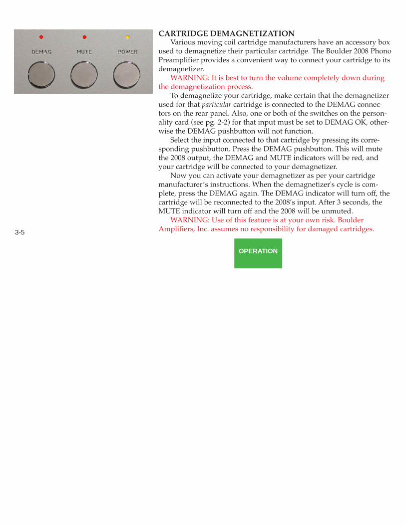
CARTRIDGE DEMAGNETIZATIONVarious moving coil cartridge manufacturers have an accessory box
used to demagnetize their particular cartridge. The Boulder 2008 PhonoPreamplifier provides a convenient way to connect your cartridge to itsdemagnetizer.
WARNING: It is best to turn the volume completely down duringthe demagnetization process.
To demagnetize your cartridge, make certain that the demagnetizerused for that particular cartridge is connected to the DEMAG connec-tors on the rear panel. Also, one or both of the switches on the person-ality card (see pg. 2-2) for that input must be set to DEMAG OK, other-wise the DEMAG pushbutton will not function.
Select the input connected to that cartridge by pressing its corre-sponding pushbutton. Press the DEMAG pushbutton. This will mutethe 2008 output, the DEMAG and MUTE indicators will be red, andyour cartridge will be connected to your demagnetizer.
Now you can activate your demagnetizer as per your cartridgemanufacturer’s instructions. When the demagnetizer's cycle is com-plete, press the DEMAG again. The DEMAG indicator will turn off, thecartridge will be reconnected to the 2008’s input. After 3 seconds, theMUTE indicator will turn off and the 2008 will be unmuted.
WARNING: Use of this feature is at your own risk. BoulderAmplifiers, Inc. assumes no responsibility for damaged cartridges.
OPERATION
3-5

MUTEThe Boulder 2008 Phono Preamplifier provides an output mute fea-
ture which is turned on by two different methods.First, the outputs are muted for three seconds when the 2008 is first
turned on or an input or equalization pushbutton is pressed. Also, itwill be muted when the demagnetization feature is on and for 3 sec-onds afterwards. The MUTE indicator will be red.
Second, the outputs may be muted at any time for your conve-nience by simply pressing the MUTE pushbutton. the MUTE indicatorwill be red.
To unmute, press the MUTE pushbutton again. The MUTE indica-tor will turn off and the outputs will unmute unless there has been a 3second cycle initiated by the first method above. In that case the out-puts will remain muted and the MUTE indicator red until that timeouthas finished.
When the POWER pushbutton is used to turn off the 2008 or thereis no power, the outputs will mute by de-energizing the unmute relay.
OPERATION
3-6

EQUALIZATIONEQUALIZATION CARDS
The Boulder 2008 Phono Preamplifier uses one of three equalizationcurves selected by the front panel pushbuttons labeled RIAA, EQ1, andEQ2. The 2008 is shipped with the RIAA as standard. Optional equal-izations may be purchased and installed by your Boulder dealer. Theseare PC cards which are installed into the EQ1 and EQ2 positions.
If no card has been installed, the EQ1 or EQ2 pushbuttons will notfunction.
The following pages show the five equalization curves, includingthe standard RIAA, available from Boulder as an option. All graphs arereferenced to 0 dB at 1 kHz. For other curves, consult your Boulderdealer.
EQUALIZATION
4-1

EQUALIZATION
4-2
RIAA REPRODUCE EQUALIZATIONREF 0 DB AT 1 KHZ

EQUALIZATION
4-3
FFRR REPRODUCE EQUALIZATIONREF 0 DB AT 1 KHZ

EQUALIZATION
4-4
EMI REPRODUCE EQUALIZATIONREF 0 DB AT 1 KHZ

EQUALIZATION
4-5
COLUMBIA REPRODUCE EQUALIZATIONREF 0 DB AT 1 KHZ

EQUALIZATION
4-6
NARTB REPRODUCE EQUALIZATIONREF 0 DB AT 1 KHZ

USING A RECORDERCONNECTIONS
A recording device may be connectedto the Boulder 2008 Phono Preamplifier.You may use balanced or unbalanced con-nections for both input and outputs aspreviously described in the sections onconnecting sources and power amplifiers.
Either of the outputs may be connect-ed to the input of your recording device.
RECORDING
6-1
RIGHTOUTPUTS
LEFTOUTPUTS

2008 AUDIO BLOCK DIAGRAM
LOW NOISE20 dB GAIN
FOR MC
1
2
3
PHONOINPUTS
DEMAG
CARTRIDGELOADING ON
PERSONALITYCARD
MM BYPASS
BALANCEDOUTPUTBUFFER
ADD 0 dB ADD 10 dB
3-POLELOW CUT
FILTER
5 Hz 10 Hz 20 Hz
PLAYBACKGAIN AND
EQUALIZATION
RIAA EQ 1 EQ 2
"OUT" BYPASS
MAINOUTPUTS
STEREO
MONO
FROM / TO OTHER
CHANNEL
1K
47K
APPENDIX
7-1

APPENDIX
7-2
BOULDER 2008 PHONO PREAMPLIFIER SPECIFICATIONSInputs 3 Balanced, Converts to UnbalancedInput Impedance, Maximum MC: 1000 Ω; MM: 47kΩ1kHz Gain, RIAA MC: 64 or 54, MM: 44 or 34dBNoise (EIN), MC 160 µV A-wtd, 275 µV Flat, 20 Hz to 20kHzOutputs 2 Balanced, for either listening or recordingMaximum Output Level 28 VrmsDistortion, THD 0.005%Output loaded with 150Ω Less than 1/2 dB distortion changeFrequency Response, 20 Hz to 20 kHz RIAA: ±0.10 dBCrosstalk, L to R or R to L -100 dB or better 20 Hz to 20kHzOutput Impedance 100Ω BalancedPreamp Size, W X H X D 18.0 x 4.25 x 15.5 inchesPower Supply Size, W X H X D 18.0 x 4.25 x 15.5 inchesPower Requirements 90-120 V / 200-240 V, 50-60 Hz, 240 W Max. (75W nominal)

APPENDIX
7-3
TROUBLESHOOTING______________________________________________________________________________________________________________SYMPTOM CAUSE REMEDY______________________________________________________________________________________________________________
No power indication on 2000 Power switch is not on Turn on power switch_________________________________________________________________________Preamplifier is not plugged in Connect to an AC outlet_________________________________________________________________________Home circuit breaker is tripped Reset circuit breaker______________________________________________________________________________________________________________
Red power indication on 2000 Low line voltage Have line voltage checked_________________________________________________________________________Power supply’s breakers tripped Reset breakers on rear panel_________________________________________________________________________Defective power supply cables Have cables tested_________________________________________________________________________Defective power supply or preamp Return to dealer for service______________________________________________________________________________________________________________
Amber POWER indication on 2008, Preamp is muted, MUTE is red Push MUTE so indicator is off_________________________________________________________________________but no sound is heard No signal from turntable Check turntable connections_________________________________________________________________________
No signal out to preamplifier Check connections to preamp_________________________________________________________________________No power supply to channel(s) Turn off power supply, check cables_________________________________________________________________________Preamp is faulty Return to dealer for servicing______________________________________________________________________________________________________________
Hum is heard No ground connection Check or install ground wire_________________________________________________________________________Duplicate ground connection Use only one ground wire to
turntable, or use the ground in abalanced cable_________________________________________________________________________
Preamp or turntable is too close to Move preamp and/or turntable2000 or other power supply away from power supply_________________________________________________________________________

APPENDIX
7-4
TROUBLESHOOTING______________________________________________________________________________________________________________SYMPTOM CAUSE REMEDY______________________________________________________________________________________________________________
One channel is louder than the other Gain switch not set equal Set gain switches on personality cards to same setting_________________________________________________________________________
MM/MC switch not set equal Set MM/MC switches on personality cards to same setting_________________________________________________________________________
Cartridge loading is not equal Check cartridge loads onpersonality cards______________________________________________________________________________________________________________

APPENDIX
7-5
NOTES