bourdon tube pressure gaugebourdon tube … · ms1 ped 2014/68/eu-1-bourdon tube pressure gauges...
TRANSCRIPT
M E A S U R I N G I N S T R U M E N T S - S T R U M E N T I P E R M I S U R A R E
BOURDON TUBE PRESSURE GAUGEBOURDON TUBE PRESSURE GAUGE

MS1
PED 2014/68/EU
-1-
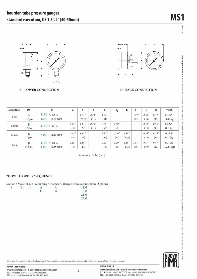
bourdon tube pressure gaugesstandard execution DS 1.5”, 2” (40-50mm)
They can be used with gaseous or liquid media which do not corrode copper alloy and which do not have high viscosity or do not cristalize.
1.01.1 - Standard Model, DS 1.5” (40mm)
Design: EN 837-1.
Ranges: from 0...30 to 0...600 psi (from 0...2,5 to 0...40 bar or equivalent
units) Accuracy class: 1,6 as per EN 837-1.
Ambient temperature: -13...+122°F (-25°C...+50°C).
Process fluid temperature : +149°F (+ 65 °C max).
Thermal drift: max ±0,4 %/10 K of range (starting from 68°F - 20°C).
Working pressure:
75% of FSV for static pressure;
66% of FSV for pulsating pressure.
Overpressure (max 15 min):
25% of FSV for ranges ≤ 1500 psi (100 bar);
15% of FSV for ranges over 1500 psi (100 bar).
Protection degree: IP 40 as per IEC 529.
Socket material: copper alloy.
Bourdon tube: copper alloy.
Welding: copper alloy.
Case: stainless steel
Window: plastic.
Movement: copper alloy.
Dial: aluminium, white with black markings
Pointer: non adjustable, aluminium, black.
1.01.1 - Standard Model, DS 2” (50mm)
Ranges: from 0...30 to 0...6000 psi ; (from 0...2,5 to 0...400 bar or other
equivalent units).
Ambient temperature: -13...+149°F ( -25°C...+65°C).
Other features: as Standard Model, DS 1.5” (40mm).
ISO 9001 : 2008Cert. nr. 0433/6
MS1
RC
6 -
10
/16
F a b c d d1
h p L ch
11M - G 1/8 A
21M - G 1/4 A
13M - 1/8-27 NPT
11M - G 1/8 A
13M - 1/8-27 NPT
23M - 1/4-18 NPT
A
B
B
B
bourdon tube pressure gaugesstandard execution, DS 1.5”, 2” (40-50mm)
dimensions : inches (mm)
Mounting DS Weight
1.5” (40)
2” (50)
2” (50)
2” (50)
(4)
0.15”
(4)
0.15”
(4)
0.15”
(26,5)
1.04”
(29)
(29)
(29)
(11)
0.43”
(11)
(41)
1.61”
(56)
(56)
(56)
(51)
(51)
(51)
(47,9)
(47,9)
(45)
1.77”
(15)
(10)
(12)
0.47”
(14)
0.55”
(14)
0.55”
(12)
0.47”
(0,07 kg)
0.15 lbs
(0,1 kg)
0.22 lbs
(0,1 kg)
0.22 lbs
(0,085 kg)
0.18 lbs
2.00”2.20”0.43”1.14”
0.59”1.88”2.00”2.20”1.14”
0.39”1.88”2.00”2.20”1.14”
Back
Lower
Lower
Back(46)
1.81”
(10)
0.39”
(13)
0.51”
D - BACK CONNECTIONA - LOWER CONNECTION
“HOW TO ORDER” SEQUENCE
Section / Model /Case / Mounting / Diameter / Range / Process connection / Options
1 01 1 A A 11M D B 13M 21M 23M
IN O
RD
ER
TO
IM
PR
OV
E T
HE
IR P
RO
DU
CT
ION
, ME
SSR
S. N
UO
VA
FIM
A R
ESE
RV
E T
HE
RIG
HT
TO
TH
EM
SELV
ES
TO
MA
KE
AL
L T
HE
MO
DIF
ICA
TIO
NS
TH
AT
TH
EY
DE
EM
IN
DIS
PE
NSA
BL
E A
T A
NY
TIM
E. U
PD
AT
ED
DA
TA
-SH
EE
TS
AR
E A
VA
ILA
BL
E O
N S
ITE
: ww
w.n
uo
vafi
ma.
com
NUOVA FIMA S.p.A. - www.nuovafima.comP.O. BOX 58 - VIA C. BATTISTI 59 - 28045 INVORIO (NO) ITALYTEL. +39 0322 253200 - FAX +39 0322 253232
Copyright © Nuova Fima srl. All rights reserved. Any part of this publication should not be reproduced without a written Nuova Fima’s srl approval

-1-
MS1
PED 2014/68/EU
-1-
They can be used with gaseous or liquid media which do not corrode copper alloy and which do not have high viscosity or do not cristalize.
bourdon tube pressure gauges DS 6” (150mm)
1.01.1 - Standard Model
Design: EN837-1.
Safety designation: S1 as per EN 837-2.
Ranges: from 0...15 to 0...15000 psi (from 0...1 to 0...1000 bar or
equivalent units).
Accuracy class: 1,6 as per EN 837-1.
Ambient temperature: -13...+149°F (-25...+65 °C).
Process fluid temperature:
13...+149°F (-25...+65 °C) for ranges ≤ 600 psi (40 bar);
-13...+ 248°F ( -25...+120 °C) for ranges ≥ 1000 psi (60 bar).
Thermal drift: max ±0,4 %/10 K of range (starting from +68°F - 20°C).
Working pressure:
75% of FSV for static pressure;
66% of FSVfor pulsating pressure.
Overpressure (max 15 min):
25% of FSV for ranges ≤ 1500 psi (100 bar);
15% of FSV for ranges more than 1500 psi (100 bar).
Protection degree: IP 44 as per IEC 529.
Socket material: copper alloy, internal restrictor Ø 0.03” (0,8 mm).
Bourdon tube: copper alloy for ranges ≤ 600 psi (40 bar); AISI 316L
st.st. for ranges > 1000 psi (60 bar).
Case: stainless steel.
Ring: stainless steel, bayonet lock
Window: tempered glass.
Movement: copper alloy.
Dial:aluminium, white with black markings
Pointer: non adjustable, aluminium, black
ISO 9001 : 2008Cert. nr. 0433/6

MS1
RC
6 -
03
/14
F a c d d1
h p Lb e
41M - G 1/2 A
43M - 1/2-14 NPT
41M - G 1/2 A
43M - 1/2-14 NPT
K10 -
L21 -
T32 -
B -
C -
E -
bourdon tube pressure gaugesDS 6” (150mm)
Maximum pointer IP 44 on plexiglas window (1)
Safety glass window
Accuracy class 1,0%
OPTIONS
(1) Accuracy refers to the area free from the maximum pointer action.
dimensions : inches (mm)
“U”-clamp, for back connection pressure gauges
Back flange, for lower connection pressure gauges
Front flange, for back connection pressure gauges
Lower
Mounting
Back
Weight
(15)
0.59”
(15)
0.59”
(16,5)
0.16”(161)
6.33”(149,6)
5.88”
(149,6) (31)
(117)
4.60” (20)
0.78”
(20)
0.78”
(1,11 kg)
2.44 lbs
(1,0 kg)
2.20 lbs1.22”5.88”(89)
3.50”
(50,5)
1.98”
(50,5)
1.98”
ES
(22)
0.86”
(22)
0.86”(161)
6.33”
D - BACK CONNECTIONA - LOWER CONNECTION
“HOW TO ORDER” SEQUENCE
Section / Model /Case / Mounting / Diameter / Range / Process connection / Options
1 01 1 A G 41M B, C, E D 43M K10...T32
IN O
RD
ER
TO
IM
PR
OV
E T
HE
IR P
RO
DU
CT
ION
, ME
SSR
S. N
UO
VA
FIM
A R
ESE
RV
E T
HE
RIG
HT
TO
TH
EM
SELV
ES
TO
MA
KE
AL
L T
HE
MO
DIF
ICA
TIO
NS
TH
AT
TH
EY
DE
EM
IN
DIS
PE
NSA
BL
E A
T A
NY
TIM
E. U
PD
AT
ED
DA
TA
-SH
EE
TS
AR
E A
VA
ILA
BL
E O
N S
ITE
: ww
w.n
uo
vafi
ma.
com
NUOVA FIMA S.p.A. - www.nuovafima.comP.O. BOX 58 - VIA C. BATTISTI 59 - 28045 INVORIO (NO) ITALYTEL. +39 0322 253200 - FAX +39 0322 253232
Copyright © Nuova Fima srl. All rights reserved. Any part of this publication should not be reproduced without a written Nuova Fima’s srl approval
-1-
MS4
PED 2014/68/EU
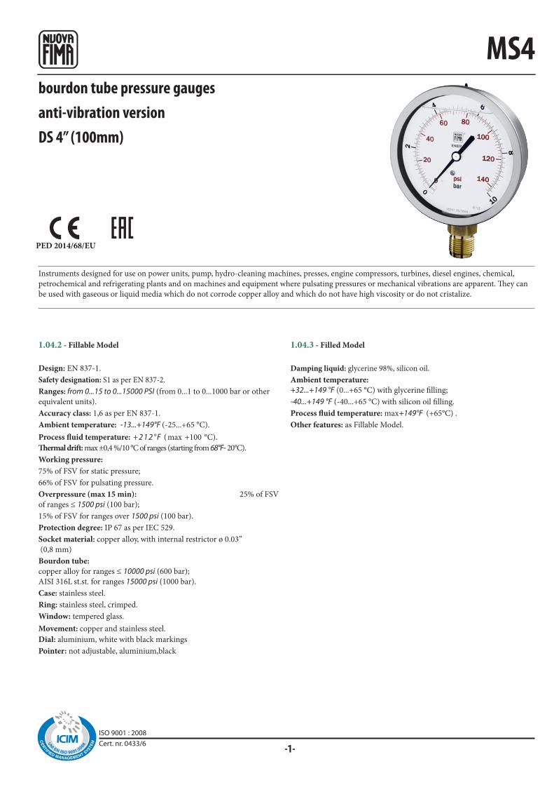
bourdon tube pressure gaugesanti-vibration versionDS 4” (100mm)
Instruments designed for use on power units, pump, hydro-cleaning machines, presses, engine compressors, turbines, diesel engines, chemical,
petrochemical and refrigerating plants and on machines and equipment where pulsating pressures or mechanical vibrations are apparent. They can
be used with gaseous or liquid media which do not corrode copper alloy and which do not have high viscosity or do not cristalize.
1.04.2 - Fillable Model
Design: EN 837-1.
Safety designation: S1 as per EN 837-2.
Ranges: from 0...15 to 0...15000 PSI (from 0...1 to 0...1000 bar or other
equivalent units).
Accuracy class: 1,6 as per EN 837-1.
Ambient temperature: -13...+149°F (-25...+65 °C).
Process fluid temperature: + 2 1 2 ° F (max +100 °C).
Thermal drift: max ±0,4 %/10 °C of ranges (starting from 68°F- 20°C).
Working pressure:
75% of FSV for static pressure;
66% of FSV for pulsating pressure.
Overpressure (max 15 min): 25% of FSV
of ranges ≤ 1500 psi (100 bar);
15% of FSV for ranges over 1500 psi (100 bar).
Protection degree: IP 67 as per IEC 529.
Socket material: copper alloy, with internal restrictor ø 0.03”
(0,8 mm)
Bourdon tube:
copper alloy for ranges ≤ 10000 psi (600 bar);
AISI 316L st.st. for ranges 15000 psi (1000 bar).
Case: stainless steel.
Ring: stainless steel, crimped.
Window: tempered glass.
Movement: copper and stainless steel.
Dial: aluminium, white with black markings
Pointer: not adjustable, aluminium,black
1.04.3 - Filled Model
Damping liquid: glycerine 98%, silicon oil.
Ambient temperature:
+32...+149 °F (0...+65 °C) with glycerine filling;
-40...+149 °F (-40...+65 °C) with silicon oil filling.
Process fluid temperature: max+149°F (+65°C) .
Other features: as Fillable Model.
ISO 9001 : 2008Cert. nr. 0433/6

◆◆ ◆
MS4
◆
◆◆◆
◆◆◆
RC
6 -
03
/14
41M - G 1/2 A
41M - G 1/2 A
43M - 1/2-14 NPT
43M - 1/2-14 NPT
P01 -
S06 -
S10 -
B -
C -
E -
F a b c d d1
e (3) h p Lch
(1) Add 0.5 Ibs (0,23 kg) when filled - (2) Add 0.53 Ibs (0,24 kg) when filled
bourdon tube pressure gaugesanti-vibration version, DS 4” (100mm)
OPTIONS
Model
Suitable for filling with silicone
Restrictor plug ø 0.01” (0,4 mm)
Silicone filling
“U”-clamp, for back connection pressure gauges
Back flange, for lower connection pressure gauges
Front flange, for back connection pressure gauges
fillable filled
Lower
Mounting
Back
Weight
(7,5)
0.29”
(7,5)
0.29”
(34)
1.33”
(34)
(11)
0.43”(110)
4.33”
(110)
(101)
3.97”
(101)
(87)
3.42”(20)
0.78”
(20)
0.78”
(0,4 kg)
0.88 lbs (1)
(0,36 kg)
0.79 lbs (2)3.97”4.33”1.33”
(22)
0.86”
(22)
0.86”(18,5)
0.73”(75)
2.95”
D - BACK CONNECTIONA - LOWER CONNECTION
“HOW TO ORDER” SEQUENCE
Section / Model /Case / Mounting / Diameter / Range / Process connection / Options
1 04 2 A E 41M B, C, E 3 D 43M P01...S10
IN O
RD
ER
TO
IM
PR
OV
E T
HE
IR P
RO
DU
CT
ION
, ME
SSR
S. N
UO
VA
FIM
A R
ESE
RV
E T
HE
RIG
HT
TO
TH
EM
SELV
ES
TO
MA
KE
AL
L T
HE
MO
DIF
ICA
TIO
NS
TH
AT
TH
EY
DE
EM
IN
DIS
PE
NSA
BL
E A
T A
NY
TIM
E. U
PD
AT
ED
DA
TA
-SH
EE
TS
AR
E A
VA
ILA
BL
E O
N S
ITE
: ww
w.n
uo
vafi
ma.
com
NUOVA FIMA S.p.A. - www.nuovafima.comP.O. BOX 58 - VIA C. BATTISTI 59 - 28045 INVORIO (NO) ITALYTEL. +39 0322 253200 - FAX +39 0322 253232
Copyright © Nuova Fima srl. All rights reserved. Any part of this publication should not be reproduced without a written Nuova Fima’s srl approval

-1-
MGS10
PED 2014/68/EU
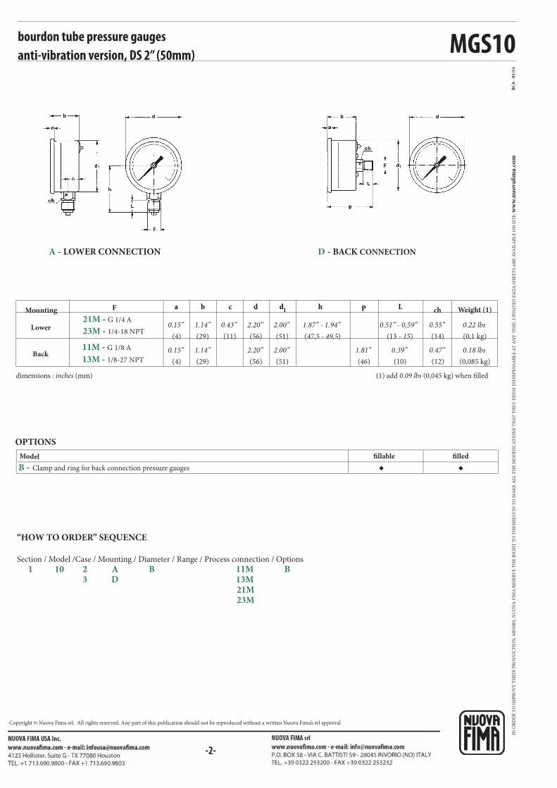
bourdon tube pressure gaugesanti-vibration versionDS 2” (50mm)
Instruments designed for use on power units, pumps, hydro-cleaning machines, presses, engine compressors, turbines, diesel engines, chemical,
petrochemical and refrigerating plants and on machines and equipment where pulsating pressures or mechanical vibrations are apparent. They can
be used with gaseous or liquid media which do not corrode copper alloy and which do not have high viscosity or do not cristalize.
1.10.2 - Fillable Model
Design: EN 837-1.
Ranges: from 0...30 to 0...6000 psi (from 0...2,5 to 0...400 bar)
Accuracy class: 1,6 as per EN 837-1.
Ambient temperature: -13...+149°F (-25...+65 °C).
Process fluid temperature: +248°F (max +120 °C).
Thermal drift: max ±0,4 %/10 °C of ranges (starting from +68°F - 20°C).
Working overpressure:
75% of FSV for static pressure;
66% of FSV for pulsating pressure;
Overpressure (max 15 min):
25% of FSV of ranges ≤ 1450 psi (100 bar);
15% of FSV for ranges over 1450 psi (100 bar).
Protection degree: IP 65 as per IEC 529.
Socket material: copper alloy.
Bourdon tube: copper alloy.
Case: stainless steel.
Window: plastic.
Movement: copper alloy.
Dial: aluminium,white with black markings.
Pointer: not adjustable, aluminium,black
1.10.3 - Filled Model
Damping liquid: glycerine 98%.
Ambient temperature: +32...+149°F (0...+65 °C).
Process fluid temperature: +149°F (max +65 °C).
Other features: as fillable model.
ISO 9001 : 2008Cert. nr. 0433/6
MGS10
◆ ◆
RC
6 -
03
/14
F a b c d d1
h p L
21M - G 1/4 A
23M - 1/4-18 NPT
11M - G 1/8 A
13M - 1/8-27 NPT
B -
D - BACK CONNECTIONA - LOWER CONNECTION
(1) add 0.09 lbs (0,045 kg) when filled
bourdon tube pressure gaugesanti-vibration version, DS 2” (50mm)
dimensions : inches (mm)
Model
OPTIONS
fillable filled
Clamp and ring for back connection pressure gauges
Lower
Mounting
Back
Weight (1)
(4)
0.15”
(4)
0.15”
(29)
1.14”
(29)
(11)
0.43”(56)
2.20”
(56)
(51)
2.00”
(51)
(47,5 - 49,5)
1.87” - 1.94” (13 - 15)
0.51” - 0,59”
(10)
0.39”
(0,1 kg)
0.22 lbs
(0,085 kg)
0.18 lbs2.00”2.20”1.14”(46)
1.81”
ch
(14)
0.55”
(12)
0.47”
“HOW TO ORDER” SEQUENCE
Section / Model /Case / Mounting / Diameter / Range / Process connection / Options
1 10 2 A B 11M B 3 D 13M 21M 23M
IN O
RD
ER
TO
IM
PR
OV
E T
HE
IR P
RO
DU
CT
ION
, ME
SSR
S. N
UO
VA
FIM
A R
ESE
RV
E T
HE
RIG
HT
TO
TH
EM
SELV
ES
TO
MA
KE
AL
L T
HE
MO
DIF
ICA
TIO
NS
TH
AT
TH
EY
DE
EM
IN
DIS
PE
NSA
BL
E A
T A
NY
TIM
E. U
PD
AT
ED
DA
TA
-SH
EE
TS
AR
E A
VA
ILA
BL
E O
N S
ITE
: ww
w.n
uo
vafi
ma.
com
NUOVA FIMA S.p.A. - www.nuovafima.comP.O. BOX 58 - VIA C. BATTISTI 59 - 28045 INVORIO (NO) ITALYTEL. +39 0322 253200 - FAX +39 0322 253232
Copyright © Nuova Fima srl. All rights reserved. Any part of this publication should not be reproduced without a written Nuova Fima’s srl approval
-1-
MGS10
PED 2014/68/EU
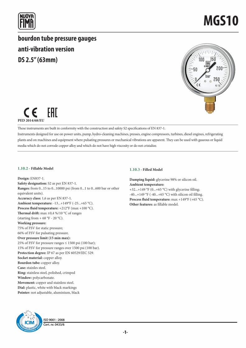
bourdon tube pressure gaugesanti-vibration versionDS 2.5” (63mm)
1.10.2 - Fillable Model
Design: EN837-1.
Safety designation: S2 as per EN 837-1.
Ranges: from 0...15 to 0...10000 psi (from 0...1 to 0...600 bar or other
equivalent units).
Accuracy class: 1,6 as per EN 837-1.
Ambient temperature: -13...+149°F (-25...+65 °C).
Process fluid temperature: +212°F (max +100 °C).
Thermal drift: max ±0,4 %/10 °C of ranges
(starting from + 68 °F - 20 °C).
Working pressure:
75% of FSV for static pressure;
66% of FSV for pulsating pressure.
Over pressure limit (15 min max):
25% of FSV for pressure ranges ≤ 1500 psi (100 bar);
15% of FSV for pressure ranges over 1500 psi (100 bar).
Protection degree: IP 67 as per EN 60529/IEC 529.
Socket material: copper alloy.
Bourdon tube: copper alloy.
Case: stainles steel.
Ring: stainless steel, polished, crimped
Window: polycarbonate.
Movement: copper and stainless steel.
Dial: plastic, white with black markings
Pointer: not adjustable, aluminium, black
1.10.3 - Filled Model
Damping liquid: glycerine 98% or silicon oil.
Ambient temperature:
+32...+149 °F (0...+65 °C) with glycerine filling;
-40...+149 °F (-40...+65 °C) with silicon oil filling.
Process fluid temperature: max +149°F (+65 °C).
Other features: as fillable model.
These instruments are built in conformity with the construction and safety S2 specifications of EN 837-1.
Instruments designed for use on power units, pump, hydro-cleaning machines, presses, engine compressors, turbines, diesel engines, refrigerating
plants and on machines and equipment where pulsating pressures or mechanical vibrations are apparent. They can be used with gaseous or liquid
media which do not corrode copper alloy and which do not have high viscosity or do not cristalize.
ISO 9001 : 2008Cert. nr. 0433/6ISO 9001 : 2008Cert. nr. 0433/6

MGS10
RC
6 -
03
/14
◆
◆◆◆
◆ ◆◆ ◆◆ ◆◆ ◆◆ ◆
d1F a b c d h p L ch
21M - G 1/4 A
23M - 1/4-18 NPT
21M - G 1/4 A
23M - 1/4-18 NPT
B -
C -
E -
Q03 -
S06 -
P01 - S10 -
T37 -
bourdon tube pressure gauge
anti-vibration version DS 2.5” (63mm)
D - BACK CONNECTIONA - LOWER CONNECTION
IN O
RD
ER
TO
IM
PR
OV
E T
HE
IR P
RO
DU
CT
ION
, ME
SSR
S. N
UO
VA
FIM
A R
ESE
RV
E T
HE
RIG
HT
TO
TH
EM
SELV
ES
TO
MA
KE
AL
L T
HE
MO
DIF
ICA
TIO
NS
TH
AT
TH
EY
DE
EM
IN
DIS
PE
NSA
BL
E A
T A
NY
TIM
E. U
PD
AT
ED
DA
TA
-SH
EE
TS
AR
E A
VA
ILA
BL
E O
N S
ITE
: ww
w.n
uo
vafi
ma.
com
NUOVA FIMA S.p.A. - www.nuovafima.comP.O. BOX 58 - VIA C. BATTISTI 59 - 28045 INVORIO (NO) ITALYTEL. +39 0322 253200 - FAX +39 0322 253232
Copyright © Nuova Fima srl. All rights reserved. Any part of this publication should not be reproduced without a written Nuova Fima’s srl approval
dimensions : inches (mm)
OPTIONS
Model
Suitable for filling with silicone
Silicone filling
Tempered glass window
fillable filled
“U”-clamp, for back connection pressure gauges
Back flange, for lower connection pressure gauges
Front flange, for back connection pressure gauges
(1) add 0.15 lbs (0,07 kg) when filled
Dial: aluminium (min. 100 pz)
Restrictor plug ø 0.015 “ (0,4 mm).
Lower
Mounting
Back
Weight (1)
(5,6)
0.22”
(5,6)
0.22”
(28)
1.10”
(28)
(10)
0.39”(68)
2.67”
(68)
(62,6)
2.46”
(62,6)
(55,3 - 54,3)2.17” - 2.13”
(13)
0.51”
(13)
0.39”
(0,13 kg)
0.28 lbs
(0,14 kg)
0.30 lbs2.46”2.67”1.10”(54,8 - 53,8)
1.81” - 2.11”
(14 x 9)
0.51” x 0.35”
(14 x 9)
0.51” x 0.35”
“HOW TO ORDER” SEQUENCE
Section / Model /Case / Mounting / Diameter / Range / Process connection / Options
1 10 2 A C 21M B, C, E 3 D 23M Q03...T37
(1) Safety designation: S1 as per EN 837-1.
-1-
MGS10
PED 2014/68/EU
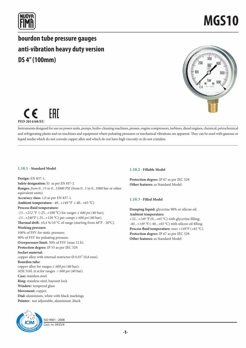
bourdon tube pressure gaugesanti-vibration heavy duty versionDS 4” (100mm)
1.10.1 - Standard Model
Design: EN 837-1.
Safety designation: S1 as per EN 837-2.
Ranges: from 0...15 to 0...15000 PSI (from 0...1 to 0...1000 bar or other
equivalent units).
Accuracy class: 1,0 as per EN 837-1.
Ambient temperature: -40...+149 °F (-40...+65 °C)
Process fluid temperature:
-13...+212 °F (-25...+100 °C) for ranges ≤ 600 psi (40 bar);
-13...+248°F (-25...+120 °C) per campi ≥ 600 psi (40 bar).
Thermal drift: ±0,4 %/10 °C of range (starting from 68°F - 20°C).
Working pressure:
100% of FSV for static pressure;
90% of FSV for pulsating pressure.
Overpressure limit: 30% of FSV (max 12 h).
Protection degree: IP 55 as per IEC 529.
Socket material:
copper alloy with internal restrictor Ø 0.03” (0,8 mm).
Bourdon tube:
copper alloy for ranges ≤ 600 psi (40 bar);
AISI 316L st.st.for ranges > 600 psi (40 bar).
Case: stainless steel.
Ring: stainless steel, bayonet lock
Window: tempered glass
Movement: copper.
Dial: aluminium, white with black markings
Pointer: not adjustable, aluminium ,black
1.10.2 - Fillable Model
Protection degree: IP 67 as per IEC 529.
Other features: as Standard Model.
1.10.3 - Filled Model
Damping liquid: glycerine 98% or silicon oil.
Ambient temperature:
+32...+149 °F (0...+65 °C) with glycerine filling;
-40...+149 °F (-40...+65 °C) with silicon oil filling.
Process fluid temperature: max +149°F (+65 °C).
Protection degree: IP 67 as per IEC 529.
Other features: as Standard Model
Instruments designed for use on power units, pumps, hydro-cleaning machines, presses, engine compressors, turbines, diesel engines, chemical, petrochemical
and refrigerating plants and on machines and equipment where pulsating pressures or mechanical vibrations are apparent. They can be used with gaseous or
liquid media which do not corrode copper alloy and which do not have high viscosity or do not cristalize.
ISO 9001 : 2008Cert. nr. 0433/6

MGS10
◆
◆◆
◆
◆
◆◆
◆ ◆ ◆◆ ◆ ◆◆ ◆ ◆
d1
RC
6 -
03
/14
F a b c d e p Lchh
41M - G 1/2 A
43M - 1/2-14 NPT
41M - G 1/2 A
43M - 1/2-14 NPT
L22 -
B - C -
E -
P01 -
S10 -
T32 -
Back flange, for lower connection pressure gauges
bourdon tube pressure gaugeanti-vibration heavy duty version, DS 4” (100mm)
(1) Accuracy refers to the area free from the maximum pointer action.
Model
Maximum pointer IP 67 on polycarbonate window (1)
Suitable for filling with silicone
Silicone filling
Safety glass window
OPTIONS
standard fillable filled
“U”-clamp, for back connection pressure gauges
Front flange, for back connection pressure gauges
dimensions : inches (mm) (1) add 0.72 lbs (0,33 kg) when filled
Lower
Mounting
Back
Weight (1)L
(13)
0.51”
(13)
0.51”
(48,6)
1.91”
(48,6)
(16,1)
0.63”(110,6)
4.35”
(110,6)
(101)
3.97”
(101)
(20)
0.78”
(20)
0.78”
(0,52 kg)
1.14 lbs
(0,57 kg)
1.25 lbs3.97”4.35”1.91”(86,8)
3.41”
(22)
0.86”
(22)
0.86”(31)
1.22”
(86)
3.38”
D - BACK CONNECTIONA - LOWER CONNECTION
“HOW TO ORDER” SEQUENCE
Section / Model /Case / Mounting / Diameter / Range / Process connection / Options
1 10 1 A E 41M B, C, E 2 D 43M L22...T32 3
IN O
RD
ER
TO
IM
PR
OV
E T
HE
IR P
RO
DU
CT
ION
, ME
SSR
S. N
UO
VA
FIM
A R
ESE
RV
E T
HE
RIG
HT
TO
TH
EM
SELV
ES
TO
MA
KE
AL
L T
HE
MO
DIF
ICA
TIO
NS
TH
AT
TH
EY
DE
EM
IN
DIS
PE
NSA
BL
E A
T A
NY
TIM
E. U
PD
AT
ED
DA
TA
-SH
EE
TS
AR
E A
VA
ILA
BL
E O
N S
ITE
: ww
w.n
uo
vafi
ma.
com
NUOVA FIMA S.p.A. - www.nuovafima.comP.O. BOX 58 - VIA C. BATTISTI 59 - 28045 INVORIO (NO) ITALYTEL. +39 0322 253200 - FAX +39 0322 253232
Copyright © Nuova Fima srl. All rights reserved. Any part of this publication should not be reproduced without a written Nuova Fima’s srl approval
-1-
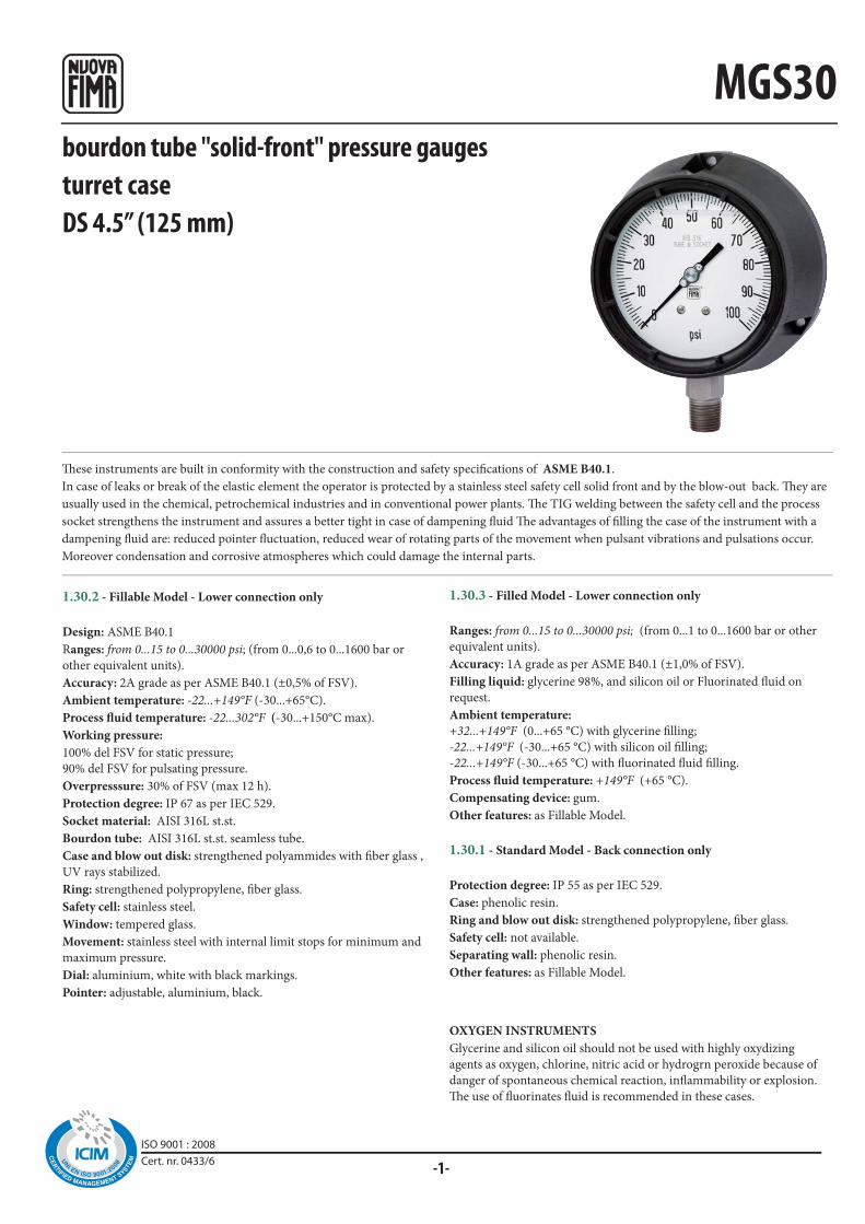
MGS30bourdon tube "solid-front" pressure gaugesturret caseDS 4.5” (125 mm)
These instruments are built in conformity with the construction and safety specifications of ASME B40.1.
In case of leaks or break of the elastic element the operator is protected by a stainless steel safety cell solid front and by the blow-out back. They are
usually used in the chemical, petrochemical industries and in conventional power plants. The TIG welding between the safety cell and the process
socket strengthens the instrument and assures a better tight in case of dampening fluid The advantages of filling the case of the instrument with a
dampening fluid are: reduced pointer fluctuation, reduced wear of rotating parts of the movement when pulsant vibrations and pulsations occur.
Moreover condensation and corrosive atmospheres which could damage the internal parts.
1.30.2 - Fillable Model - Lower connection only
Design: ASME B40.1
Ranges: from 0...15 to 0...30000 psi; (from 0...0,6 to 0...1600 bar or
other equivalent units).
Accuracy: 2A grade as per ASME B40.1 (±0,5% of FSV).
Ambient temperature: -22...+149°F (-30...+65°C).
Process fluid temperature: -22...302°F (-30...+150°C max).
Working pressure:
100% del FSV for static pressure;
90% del FSV for pulsating pressure.
Overpresssure: 30% of FSV (max 12 h).
Protection degree: IP 67 as per IEC 529.
Socket material: AISI 316L st.st.
Bourdon tube: AISI 316L st.st. seamless tube.
Case and blow out disk: strengthened polyammides with fiber glass ,
UV rays stabilized.
Ring: strengthened polypropylene, fiber glass.
Safety cell: stainless steel.
Window: tempered glass.
Movement: stainless steel with internal limit stops for minimum and
maximum pressure.
Dial: aluminium, white with black markings.
Pointer: adjustable, aluminium, black.
1.30.3 - Filled Model - Lower connection only
Ranges: from 0...15 to 0...30000 psi; (from 0...1 to 0...1600 bar or other
equivalent units).
Accuracy: 1A grade as per ASME B40.1 (±1,0% of FSV).
Filling liquid: glycerine 98%, and silicon oil or Fluorinated fluid on
request.
Ambient temperature:
+32...+149°F (0...+65 °C) with glycerine filling; -22...+149°F (-30...+65 °C) with silicon oil filling;
-22...+149°F (-30...+65 °C) with fluorinated fluid filling.
Process fluid temperature: +149°F (+65 °C).
Compensating device: gum.
Other features: as Fillable Model.
1.30.1 - Standard Model - Back connection only
Protection degree: IP 55 as per IEC 529.
Case: phenolic resin.
Ring and blow out disk: strengthened polypropylene, fiber glass.
Safety cell: not available.
Separating wall: phenolic resin.
Other features: as Fillable Model.
OXYGEN INSTRUMENTS
Glycerine and silicon oil should not be used with highly oxydizing
agents as oxygen, chlorine, nitric acid or hydrogrn peroxide because of
danger of spontaneous chemical reaction, inflammability or explosion.
The use of fluorinates fluid is recommended in these cases.
ISO 9001 : 2008Cert. nr. 0433/6
◆◆
◆◆
◆
◆◆◆
◆
◆
◆
◆◆ (1)
◆◆
◆ (2)
◆ ◆◆
a1 d 1 h 1F a b c d e E f chh p L
RC
8 -
03
/14
MGS30
41M
G 1/2 A
43M
1/2-14 NPT
F11 -
F30 -
P01 -
P02 -
FDP -
F30 -
S10 -
T01 -
T32 -
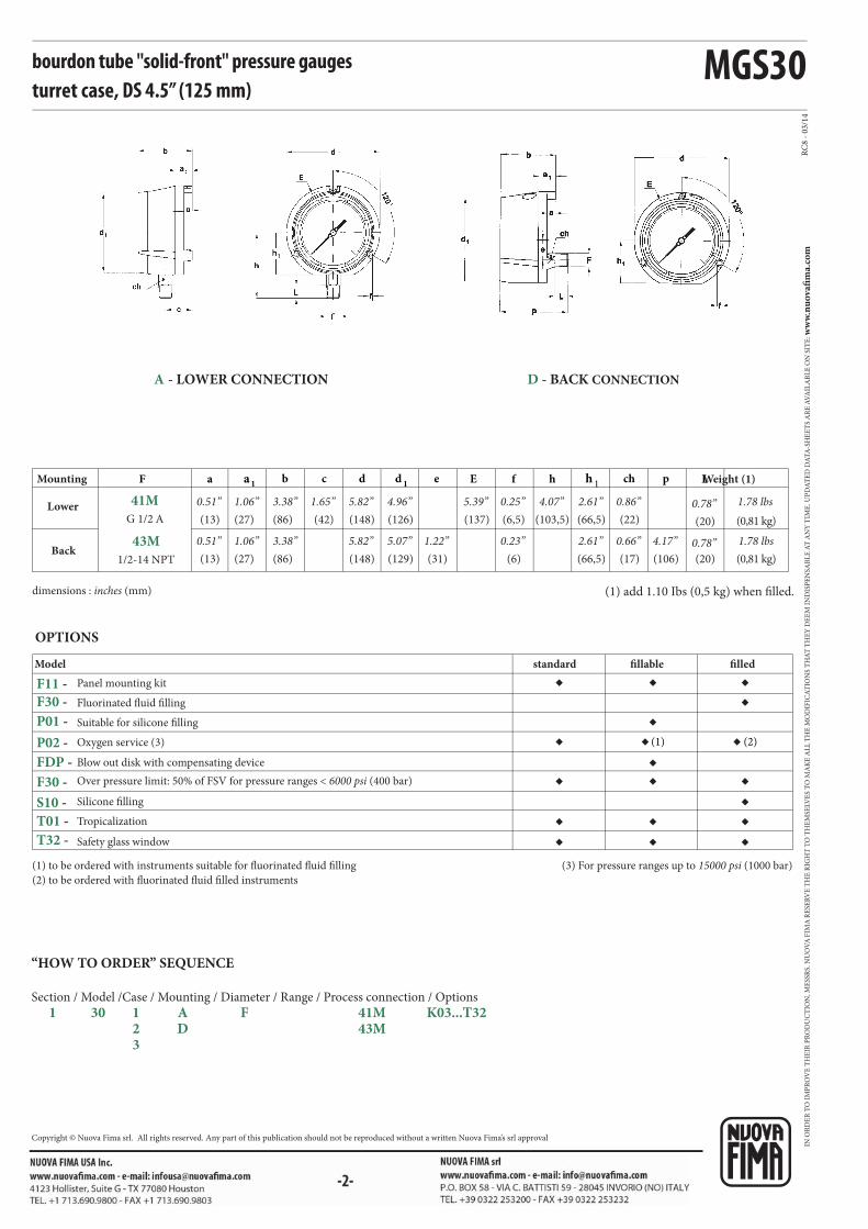
bourdon tube "solid-front" pressure gauges turret case, DS 4.5” (125 mm)
(1) to be ordered with instruments suitable for fluorinated fluid filling
(2) to be ordered with fluorinated fluid filled instruments
(3) For pressure ranges up to 15000 psi (1000 bar)
Silicone filling
Tropicalization
Safety glass window
Model
Panel mounting kit
Fluorinated fluid filling
Suitable for silicone filling
Oxygen service (3)
Blow out disk with compensating device
Over pressure limit: 50% of FSV for pressure ranges < 6000 psi (400 bar)
OPTIONS
standard fillable filled
dimensions : inches (mm) (1) add 1.10 Ibs (0,5 kg) when filled.
Lower
Mounting
Back
Weight (1)
(13)
0.51”
(13)
0.51”
(86)
3.38”
(86)
(42)
1.65”(148)
5.82”
(148)
(126)
4.96”
(129)
(137)
5.39”(22)
0.86”
(17)
0.66”(0,81 kg)
1.78 lbs
(0,81 kg)
1.78 lbs5.07”5.82”3.38”
(66,5)
2.61”
(66,5)
2.61”(31)
1.22”(6)
0.23”
(27)
1.06”
(27)
1.06”
(103,5)
4.07”
(106)
4.17”(20)
0.78”
(20)
0.78”
(6,5)
0.25”
D - BACK CONNECTIONA - LOWER CONNECTION
“HOW TO ORDER” SEQUENCE
Section / Model /Case / Mounting / Diameter / Range / Process connection / Options
1 30 1 A F 41M K03...T32 2 D 43M 3
IN O
RD
ER
TO
IM
PR
OV
E T
HE
IR P
RO
DU
CT
ION
, ME
SSR
S. N
UO
VA
FIM
A R
ESE
RV
E T
HE
RIG
HT
TO
TH
EM
SELV
ES
TO
MA
KE
AL
L T
HE
MO
DIF
ICA
TIO
NS
TH
AT
TH
EY
DE
EM
IN
DIS
PE
NSA
BL
E A
T A
NY
TIM
E. U
PD
AT
ED
DA
TA
-SH
EE
TS
AR
E A
VA
ILA
BL
E O
N S
ITE
: ww
w.n
uo
vafi
ma.
com
NUOVA FIMA S.p.A. - www.nuovafima.comP.O. BOX 58 - VIA C. BATTISTI 59 - 28045 INVORIO (NO) ITALYTEL. +39 0322 253200 - FAX +39 0322 253232
Copyright © Nuova Fima srl. All rights reserved. Any part of this publication should not be reproduced without a written Nuova Fima’s srl approval
-1-
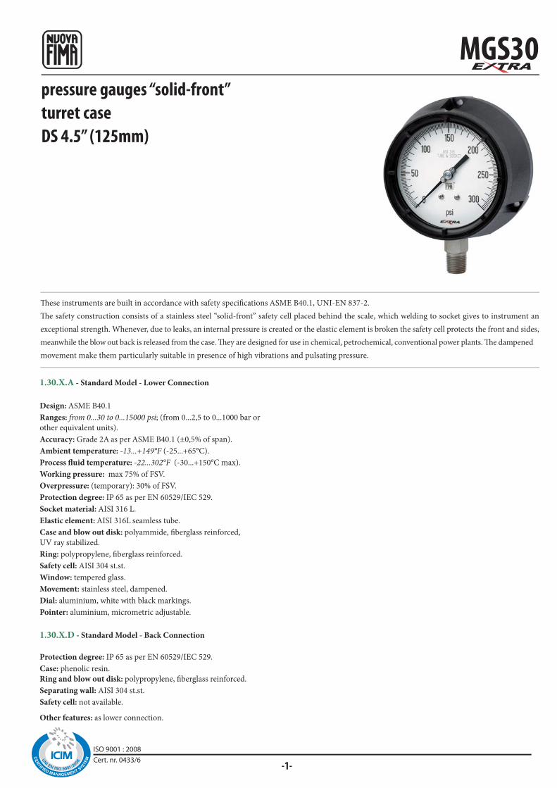
MGS30pressure gauges “solid-front”turret caseDS 4.5” (125mm)
These instruments are built in accordance with safety specifications ASME B40.1, UNI-EN 837-2.
The safety construction consists of a stainless steel “solid-front” safety cell placed behind the scale, which welding to socket gives to instrument an
exceptional strength. Whenever, due to leaks, an internal pressure is created or the elastic element is broken the safety cell protects the front and sides,
meanwhile the blow out back is released from the case. They are designed for use in chemical, petrochemical, conventional power plants. The dampened
movement make them particularly suitable in presence of high vibrations and pulsating pressure.
1.30.X.A - Standard Model - Lower Connection
Design: ASME B40.1
Ranges: from 0...30 to 0...15000 psi; (from 0...2,5 to 0...1000 bar or
other equivalent units).
Accuracy: Grade 2A as per ASME B40.1 (±0,5% of span).
Ambient temperature: -13...+149°F (-25...+65°C).
Process fluid temperature: -22...302°F (-30...+150°C max).
Working pressure: max 75% of FSV.
Overpressure: (temporary): 30% of FSV.
Protection degree: IP 65 as per EN 60529/IEC 529.
Socket material: AISI 316 L.
Elastic element: AISI 316L seamless tube.
Case and blow out disk: polyammide, fiberglass reinforced,
UV ray stabilized.
Ring: polypropylene, fiberglass reinforced.
Safety cell: AISI 304 st.st.
Window: tempered glass.
Movement: stainless steel, dampened.
Dial: aluminium, white with black markings.
Pointer: aluminium, micrometric adjustable.
1.30.X.D - Standard Model - Back Connection
Protection degree: IP 65 as per EN 60529/IEC 529.
Case: phenolic resin.
Ring and blow out disk: polypropylene, fiberglass reinforced.
Separating wall: AISI 304 st.st.
Safety cell: not available.
Other features: as lower connection.
ISO 9001 : 2008Cert. nr. 0433/6
MGS30
a1d 1 h 1F a b c d e E f chh p L
RC3 -
04/1
3
23M-1/4-18 NPT
43M-1/2-14 NPT
23M-1/4-18 NPT
43M-1/2-14 NPT
F11 -
T01 -
T25 -
T32 -
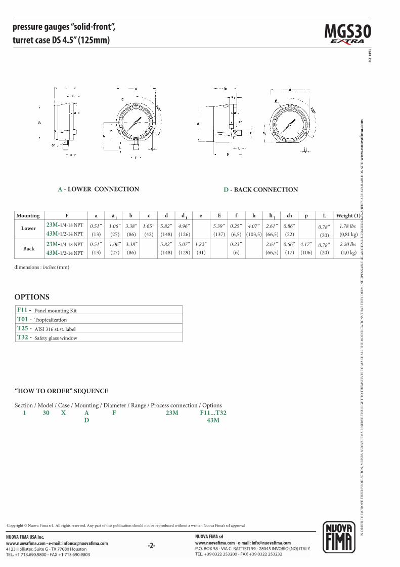
pressure gauges “solid-front”,turret case DS 4.5” (125mm)
Panel mounting Kit
Tropicalization
AISI 316 st.st. label
Safety glass window
OPTIONS
dimensions : inches (mm)
Lower
Mounting
Back
Weight (1)
(13)
0.51”
(13)
0.51”
(86)
3.38”
(86)
(42)
1.65”(148)
5.82”
(148)
(126)
4.96”
(129)
(137)
5.39”(22)
0.86”
(17)
0.66”
(0,81 kg)
1.78 lbs
(1,0 kg)
2.20 lbs5.07”5.82”3.38”
(66,5)
2.61”
(66,5)
2.61”(31)
1.22”(6)
0.23”
(27)
1.06”
(27)
1.06”
(103,5)
4.07”
(106)
4.17”(20)
0.78”
(20)
0.78”
(6,5)
0.25”
A - LOWER CONNECTION D - BACK CONNECTION
“HOW TO ORDER” SEQUENCE
Section / Model / Case / Mounting / Diameter / Range / Process connection / Options
1 30 X A F 23M F11...T32 D 43M
IN O
RD
ER
TO
IM
PR
OV
E T
HE
IR P
RO
DU
CT
ION
, ME
SSR
S. N
UO
VA
FIM
A R
ESE
RV
E T
HE
RIG
HT
TO
TH
EM
SELV
ES
TO
MA
KE
AL
L T
HE
MO
DIF
ICA
TIO
NS
TH
AT
TH
EY
DE
EM
IN
DIS
PE
NSA
BL
E A
T A
NY
TIM
E. U
PD
AT
ED
DA
TA
-SH
EE
TS
AR
E A
VA
ILA
BL
E O
N S
ITE
: ww
w.n
uo
vafi
ma.
com
NUOVA FIMA S.p.A. - www.nuovafima.comP.O. BOX 58 - VIA C. BATTISTI 59 - 28045 INVORIO (NO) ITALYTEL. +39 0322 253200 - FAX +39 0322 253232
Copyright © Nuova Fima srl. All rights reserved. Any part of this publication should not be reproduced without a written Nuova Fima’s srl approval
-1-
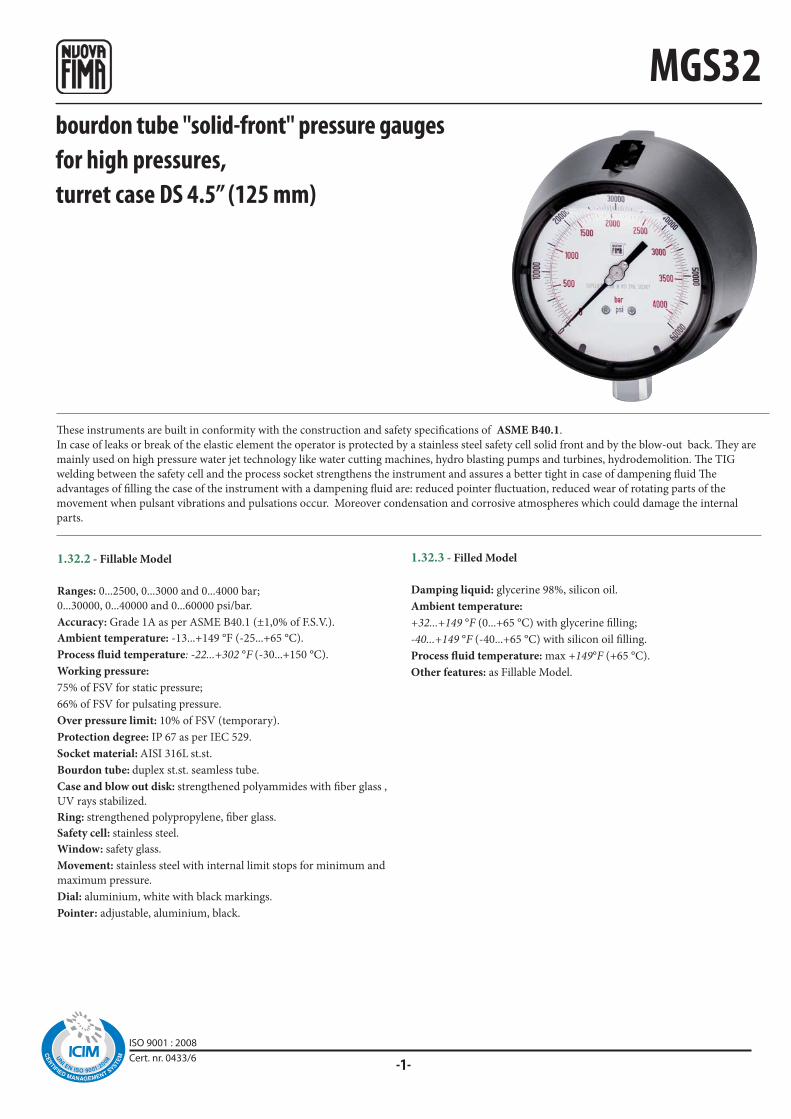
MGS32
These instruments are built in conformity with the construction and safety specifications of ASME B40.1.
In case of leaks or break of the elastic element the operator is protected by a stainless steel safety cell solid front and by the blow-out back. They are
mainly used on high pressure water jet technology like water cutting machines, hydro blasting pumps and turbines, hydrodemolition. The TIG
welding between the safety cell and the process socket strengthens the instrument and assures a better tight in case of dampening fluid The
advantages of filling the case of the instrument with a dampening fluid are: reduced pointer fluctuation, reduced wear of rotating parts of the
movement when pulsant vibrations and pulsations occur. Moreover condensation and corrosive atmospheres which could damage the internal
parts.
1.32.2 - Fillable Model
Ranges: 0...2500, 0...3000 and 0...4000 bar;
0...30000, 0...40000 and 0...60000 psi/bar.
Accuracy: Grade 1A as per ASME B40.1 (±1,0% of F.S.V.).
Ambient temperature: -13...+149 °F (-25...+65 °C).
Process fluid temperature: -22...+302 °F (-30...+150 °C).
Working pressure:
75% of FSV for static pressure;
66% of FSV for pulsating pressure.
Over pressure limit: 10% of FSV (temporary).
Protection degree: IP 67 as per IEC 529.
Socket material: AISI 316L st.st.
Bourdon tube: duplex st.st. seamless tube.
Case and blow out disk: strengthened polyammides with fiber glass ,
UV rays stabilized.
Ring: strengthened polypropylene, fiber glass.
Safety cell: stainless steel.
Window: safety glass.
Movement: stainless steel with internal limit stops for minimum and
maximum pressure.
Dial: aluminium, white with black markings.
Pointer: adjustable, aluminium, black.
1.32.3 - Filled Model
Damping liquid: glycerine 98%, silicon oil.
Ambient temperature:
+32...+149 °F (0...+65 °C) with glycerine filling;
-40...+149 °F (-40...+65 °C) with silicon oil filling.
Process fluid temperature: max +149°F (+65 °C).
Other features: as Fillable Model.
bourdon tube "solid-front" pressure gaugesfor high pressures,turret case DS 4.5” (125 mm)
ISO 9001 : 2008Cert. nr. 0433/6
◆◆◆
◆◆
◆
RC
3 -
01
/12
MGS32
F11 -
P01 -
S10 -
T01 -
Ø7.1
9/16"-18 UNF L.H.
53.5
6.35
24
59°
ø14.3
a1 d 1 h 1F a b c d E f chh
D7FM16 x 1,5
IUF9/16-18 UNF-2B
(1)
IUH9/16-18 UNF-L.H.
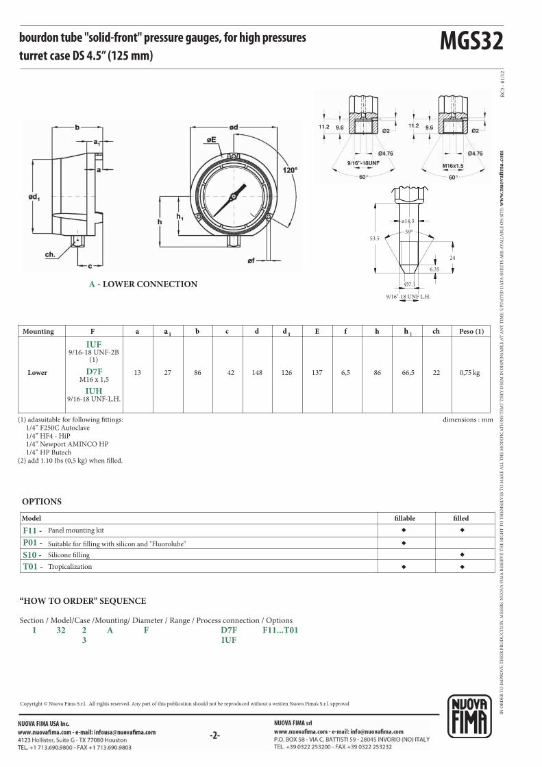
bourdon tube "solid-front" pressure gauges, for high pressures turret case DS 4.5” (125 mm)
A - LOWER CONNECTION
Silicone filling
Tropicalization
Model
Panel mounting kit
Suitable for filling with silicon and "Fluorolube"
OPTIONS
fillable filled
“HOW TO ORDER” SEQUENCE
Section / Model/Case /Mounting/ Diameter / Range / Process connection / Options
1 32 2 A F D7F F11...T01 3 IUF
dimensions : mm
Lower
Mounting Peso (1)
(1) adasuitable for following fittings: 1/4” F250C Autoclave 1/4” HF4 - HiP 1/4” Newport AMINCO HP 1/4” HP Butech(2) add 1.10 Ibs (0,5 kg) when filled.
13 86 42 148 126 137 22 0,75 kg66,527 866,5
IN O
RD
ER
TO
IM
PR
OV
E T
HE
IR P
RO
DU
CT
ION
, ME
SSR
S. N
UO
VA
FIM
A R
ESE
RV
E T
HE
RIG
HT
TO
TH
EM
SELV
ES
TO
MA
KE
AL
L T
HE
MO
DIF
ICA
TIO
NS
TH
AT
TH
EY
DE
EM
IN
DIS
PE
NSA
BL
E A
T A
NY
TIM
E. U
PD
AT
ED
DA
TA
-SH
EE
TS
AR
E A
VA
ILA
BL
E O
N S
ITE
: ww
w.n
uo
vafi
ma.
com
Copyright © Nuova Fima S.r.l. All rights reserved. Any part of this publication should not be reproduced without a written Nuova Fima’s S.r.l. approval

-1-
PED 2014/68/EU
MGS8
These instruments are designed for use in chemical and petrochemical processing industries, and in conventional power plants, built to resist the most
severe operating conditions, to measure gaseous or liquid media which do not have high viscosity or do not crystallize.
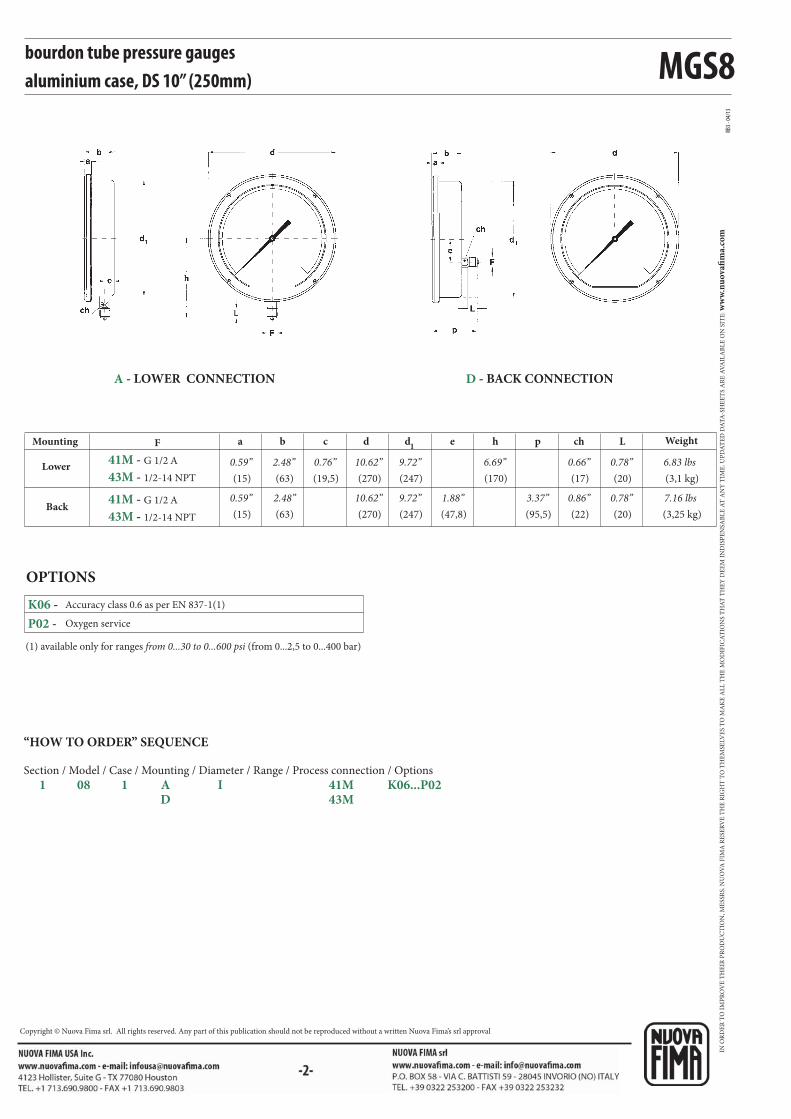
bourdon tube pressure gaugesaluminium caseDS 10” (250 mm)
1.08.1 - Standard Model
Design: EN837-1.
Safety designation: S1 as per EN 837-2.
Ranges: from 0...1 to 0...1000 bar (or other equivalent units).
Accuracy class: 1 as per EN 837-1.
Ambient temperature: -13...+149 °F (-25...+65 °C).
Process fluid temperature: -40...+302 °F (-40...+150 °C).
Thermal drift: ±0,4 %/10 K of range (starting from 68°F - 20°C).
Working pressure: 100% of
FSV for static pressure;
90% of FSV for pulsating pressure.
Over pressure limit: 30% of FSV (max 12 hours).
Protection degree: IP 55 as per EN 60529/IEC 529.
Socket material: AISI 316L st.st.
Bourdon tube: AISI 316L st.st. seamless tube.
Case: black painted aluminium.
Ring: black painted aluminium.
Window: tempered glass.
Movement: stainless steel.
Dial: aluminium, white with black markings.
Pointer: not adjustable, aluminium, black.
ISO 9001 : 2008Cert. nr. 0433/6
MGS8
RB3 -
04/1
3
41M - G 1/2 A
43M - 1/2-14 NPT
41M - G 1/2 A
43M - 1/2-14 NPT
F a b c d d1
e h p Lch
K06 -
P02 -
Accuracy class 0.6 as per EN 837-1(1)
bourdon tube pressure gaugesaluminium case, DS 10” (250mm)
OPTIONS
(1) available only for ranges from 0...30 to 0...600 psi (from 0...2,5 to 0...400 bar)
Oxygen service
Lower
Mounting
Back
Weight
(15)
0.59”
(15)
0.59”
(63)
2.48”
(63)
(19,5)
0.76”(270)
10.62”
(270)
(247)
9.72”
(247)
(170)
6.69”(20)
0.78”
(20)
0.78”
(3,1 kg)
6.83 lbs
(3,25 kg)
7.16 lbs9.72”10.62”2.48”
(17)
0.66”
(22)
0.86”(47,8)
1.88”(95,5)
3.37”
A - LOWER CONNECTION D - BACK CONNECTION
“HOW TO ORDER” SEQUENCE
Section / Model / Case / Mounting / Diameter / Range / Process connection / Options
1 08 1 A I 41M K06...P02 D 43M
IN O
RD
ER
TO
IM
PR
OV
E T
HE
IR P
RO
DU
CT
ION
, ME
SSR
S. N
UO
VA
FIM
A R
ESE
RV
E T
HE
RIG
HT
TO
TH
EM
SELV
ES
TO
MA
KE
AL
L T
HE
MO
DIF
ICA
TIO
NS
TH
AT
TH
EY
DE
EM
IN
DIS
PE
NSA
BL
E A
T A
NY
TIM
E. U
PD
AT
ED
DA
TA
-SH
EE
TS
AR
E A
VA
ILA
BL
E O
N S
ITE
: ww
w.n
uo
vafi
ma.
com
NUOVA FIMA S.p.A. - www.nuovafima.comP.O. BOX 58 - VIA C. BATTISTI 59 - 28045 INVORIO (NO) ITALYTEL. +39 0322 253200 - FAX +39 0322 253232
Copyright © Nuova Fima srl. All rights reserved. Any part of this publication should not be reproduced without a written Nuova Fima’s srl approval

-1-
MGS18
PED 2014/68/EU
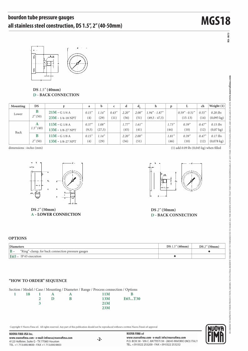
bourdon tube pressure gaugesall stainless steel constructionDS 1.5”, 2” (40-50 mm)
These instruments are designed for use in chemical and petrochemical processing industries, and in conventional power plants, to measure gaseous
or liquid media which do not have high viscosity or do not cristalize. They are built to resist the most severe operating conditions created by the
ambient environment and the process medium. For use on power units, pumps, hydro-cleaning machines, presses, engine compressors, turbines,
diesel engines, chemical, petrochemical and refrigerating plants and on machines and equipment where pulsating pressures or mechanical vibrations
are apparent, the liquid-filled version is recommended.
01.18.1 - Standard Model, DS 1.5” (40mm)
Design: EN 837-1.
Ranges: from 0…30 to 0…600 psi (from 0…2.5 to 0…40 bar or
equivalent units).
Accuracy class: 1.6 as per EN 837-1.
Ambient temperature: -13...+149 °F (-25...+65 °C).
Process fluid temperature: -22...+212 °F (-30...+100 °C).
Thermal drift: ±0,4 %/10 °C of range (starting from 68°F - 20°C).
Working pressure:
75% of FSV for static pressure;
66% of FSV for pulsating pressure.
Over pressure limit (15 min max):
25% of FSV.
Protection degree: IP 55 as per EN 60529/IEC 529.
Socket material: AISI 316L st.st.
Bourdon tube: AISI 316L st.st.
Case: stainless steel.
Ring: stainless steel, bayonet lock.
Window: glass.
Movement: stainless steel.
Dial: aluminium, white with black markings.
Pointer: not adjustable, aluminium, black.
01.18.1 - Standard Model, DS 2” (50mm)
Ambient temperature: -13...+149 °F (-25...+65 °C).
Protecti on degree: IP 55 as per EN 60529/IEC 529.
Case: stainless steel, crimped.
Ring: stainless steel, crimped.
Window: plastic.
Other features: as Standard Model, DS 1.5” (40mm).
01.18.2 - Fillable Model, DS 2” (50mm)
Protecti on degree: IP 67 as per EN 60529/IEC 529.
Other features: as Standard Model, DS 2” (50mm).
01.18.3 - Filled Model, DS 2” (50mm)
Damping liquid: glycerine 98%.
Ambient temperature: +32...+149 °F (0...+65 °C).
Process fluid temperature: max +149°F (+65 °C).
Protecti on degree: IP 67 as per IEC 529.
Other features: as Standard Model, DS 2” (50mm).
ISO 9001 : 2008Cert. nr. 0433/6
MGS18
◆◆
RC6 -
08/1
3
B
A
B
E65 -
B -
21M - G 1/4 A
23M - 1/4-18 NPT
11M - G 1/8 A
13M - 1/8-27 NPT
11M - G 1/8 A
13M - 1/8-27 NPT
bourdon tube pressure gaugesall stainless steel construction, DS 1.5”, 2” (40-50mm)
Diameters
OPTIONS
“Ring”-clamp, for back connection pressure gauges
IP 65 execution
DS 1.5” (40mm)
D - BACK CONNECTION
DS 2” (50mm)
D - BACK CONNECTION
DS 2” (50mm)A - LOWER CONNECTION
Lower
Back
dimensions : inches (mm) (1) add 0.09 lbs (0,045 kg) when filled
F a b c d d1
hMounting DS Weight (1)L
2” (50)
1.5” (40)
2” (50)
(4)
0.15”
(9,5)
(4)
0.15”
(29)
1.14”
(27,5)
(29)
(11)
0.43”(56)
2.20”
(45)
(56)
(51)
2.00”
(41)
(51)
(49,5 - 47,5)
1.94” - 1.87” (15-13)
0.59” - 0.51”
(10)
0.39”
(10)
0.39”
(0,095 kg)
0.20 Ibs
(0,07 kg)
0.15 Ibs
(0,078 kg)
0.17 Ibs2.00”2.20”1.14”
p
(44)
(46)
1.73”
1.81”
ch
(14)
0.55”
(12)
0.47”
(12)
0.47”
1.08”0.37” 1.77” 1.61”
DS 1.5” (40mm) DS 2” (50mm)
“HOW TO ORDER” SEQUENCE
Section / Model / Case / Mounting / Diameter / Range / Process connection / Options
1 18 1 A A 11M B 2 D B 13M E65...T30 3 21M 23M
IN O
RD
ER
TO
IM
PR
OV
E T
HE
IR P
RO
DU
CT
ION
, ME
SSR
S. N
UO
VA
FIM
A R
ESE
RV
E T
HE
RIG
HT
TO
TH
EM
SELV
ES
TO
MA
KE
AL
L T
HE
MO
DIF
ICA
TIO
NS
TH
AT
TH
EY
DE
EM
IN
DIS
PE
NSA
BL
E A
T A
NY
TIM
E. U
PD
AT
ED
DA
TA
-SH
EE
TS
AR
E A
VA
ILA
BL
E O
N S
ITE
: ww
w.n
uo
vafi
ma.
com
NUOVA FIMA S.p.A. - www.nuovafima.comP.O. BOX 58 - VIA C. BATTISTI 59 - 28045 INVORIO (NO) ITALYTEL. +39 0322 253200 - FAX +39 0322 253232
Copyright © Nuova Fima srl. All rights reserved. Any part of this publication should not be reproduced without a written Nuova Fima’s srl approval
-1-
MGS18
PED 2014/68/UE
1.18.1 - Standard Model
Design: EN 837-1.
Safety designation: S1 as per EN 837-1.
Ranges: from 0...15 to 0...15000 psi; (from 0...1 to 0...1000 bar),
(or other equivalent units).
Accuracy class: 1.6 as per EN 837-1.
Ambient temperature: -40...+149 °F (-40...+65 °C).
Process fluid temperature: max +212°F (+100 °C).
Thermal drift: ±0,4 %/10 °C of range (starting from 68°F - 20°C).
Working pressure:
75% of FSV for static pressure;
66% of FSV for pulsating pressure.
Over pressure limit (15 min max):
25% of FSV for pressure ranges ≤ 1500 psi (100 bar);
15% of FSV for pressure ranges 1500...9000 psi (100...600 bar);
10% of FSV for pressure ranges over 9000 psi (600 bar).
Protection degree: IP 55 as per EN 60529/IEC 529.
Socket material: AISI 316L st.st.
Bourdon tube: AISI 316L st.st.
Case: stainless steel.
Ring: stainless steel, bayonet lock.
Window: polycarbonate.
Movement: stainless steel.
Dial: plast ic white with black markings.
Pointer: adjustable, aluminium, black.
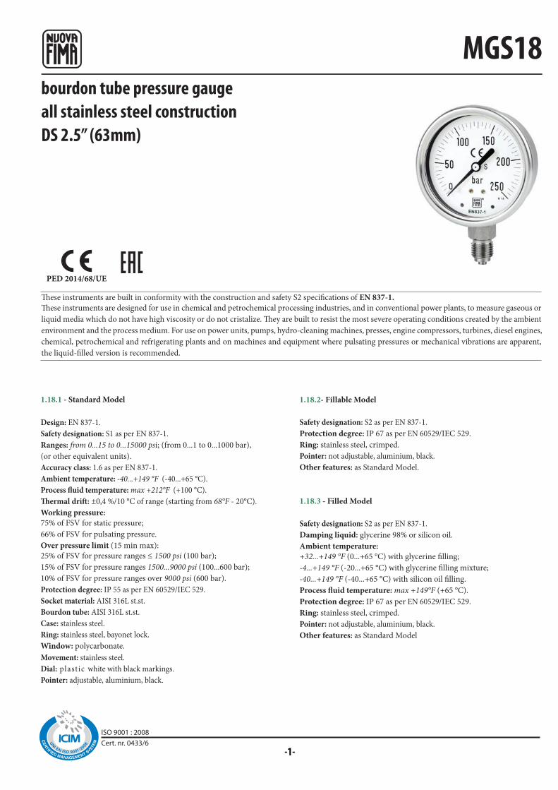
bourdon tube pressure gauge all stainless steel constructionDS 2.5” (63mm)
These instruments are built in conformity with the construction and safety S2 specifications of EN 837-1.
These instruments are designed for use in chemical and petrochemical processing industries, and in conventional power plants, to measure gaseous or
liquid media which do not have high viscosity or do not cristalize. They are built to resist the most severe operating conditions created by the ambient
environment and the process medium. For use on power units, pumps, hydro-cleaning machines, presses, engine compressors, turbines, diesel engines,
chemical, petrochemical and refrigerating plants and on machines and equipment where pulsating pressures or mechanical vibrations are apparent,
the liquid-filled version is recommended.
1.18.2- Fillable Model
Safety designation: S2 as per EN 837-1.
Protection degree: IP 67 as per EN 60529/IEC 529.
Ring: stainless steel, crimped.
Pointer: not adjustable, aluminium, black.
Other features: as Standard Model.
1.18.3 - Filled Model
Safety designation: S2 as per EN 837-1.
Damping liquid: glycerine 98% or silicon oil.
Ambient temperature:
+32...+149 °F (0...+65 °C) with glycerine filling;
-4...+149 °F (-20...+65 °C) with glycerine filling mixture;
-40...+149 °F (-40...+65 °C) with silicon oil filling.
Process fluid temperature: max +149°F (+65 °C).
Protection degree: IP 67 as per EN 60529/IEC 529.
Ring: stainless steel, crimped.
Pointer: not adjustable, aluminium, black.
Other features: as Standard Model
ISO 9001 : 2008Cert. nr. 0433/6
MGS18
◆◆
◆
◆
◆
◆◆◆
◆◆
◆
◆◆◆
1a 1a a b c d d1
h p L chF
RC
8 -
04
/13
21M - G 1/4 A
23M - 1/4-18 NPT
21M - G 1/4 A
23M - 1/4-18 NPT
P01 -
S10 -
B - C -
E -
G11 -
T37 -
T32 -
(1)
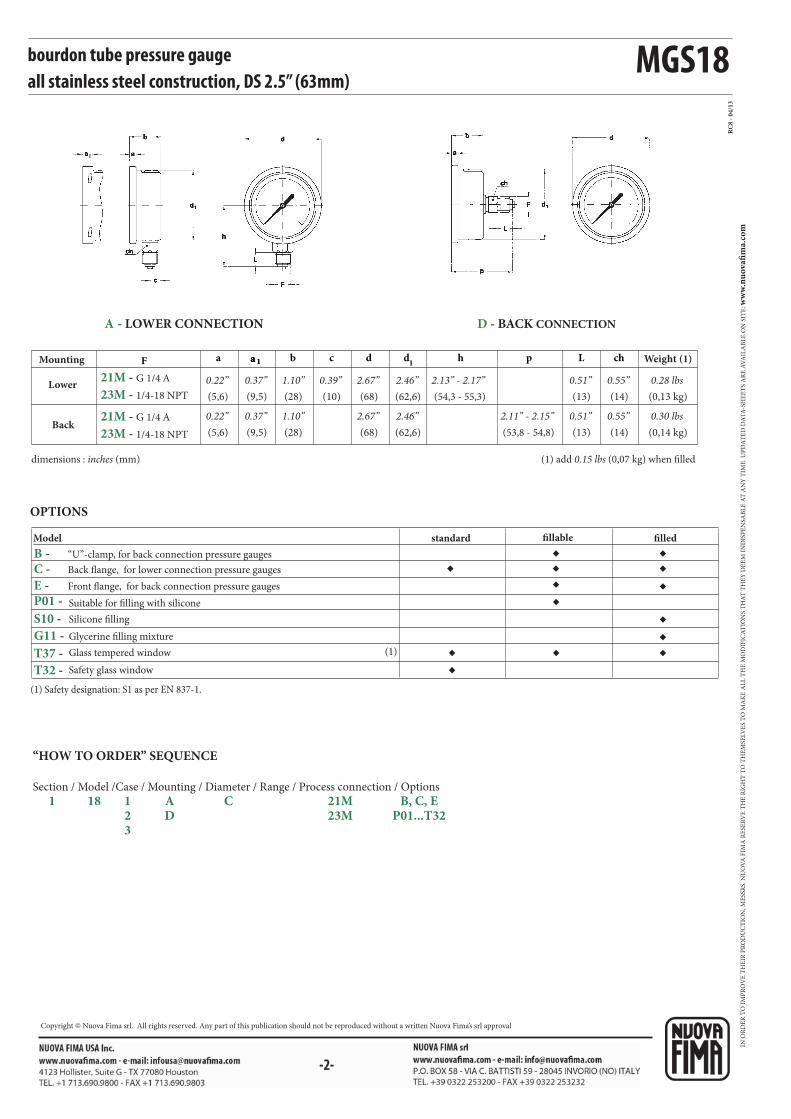
bourdon tube pressure gauge all stainless steel construction, DS 2.5” (63mm)
Suitable for filling with silicone
Silicone filling
Glass tempered window
Safety glass window
(1) add 0.15 lbs (0,07 kg) when filleddimensions : inches (mm)
Model
OPTIONS
“U”-clamp, for back connection pressure gauges
Back flange, for lower connection pressure gauges
Front flange, for back connection pressure gauges
standard fillable filled
Lower
Mounting
Back
Weight (1)
(5,6)
0.22”
(5,6)
0.22”
(28)
1.10”
(28)
(10)
0.39”(68)
2.67”
(68)
(62,6)
2.46”
(62,6)
(54,3 - 55,3)
2.13” - 2.17” (13)
0.51”
(13)
0.51”
(0,13 kg)
0.28 lbs
(0,14 kg)
0.30 lbs2.46”2.67”1.10”(53,8 - 54,8)
2.11” - 2.15”
(9,5)
0.37”
(9,5)
0.37”
(14)
0.55”
(14)
0.55”
D - BACK CONNECTIONA - LOWER CONNECTION
“HOW TO ORDER” SEQUENCE
Section / Model /Case / Mounting / Diameter / Range / Process connection / Options
1 18 1 A C 21M B, C, E 2 D 23M P01...T32 3
Glycerine filling mixture
(1) Safety designation: S1 as per EN 837-1.
IN O
RD
ER
TO
IM
PR
OV
E T
HE
IR P
RO
DU
CT
ION
, ME
SSR
S. N
UO
VA
FIM
A R
ESE
RV
E T
HE
RIG
HT
TO
TH
EM
SELV
ES
TO
MA
KE
AL
L T
HE
MO
DIF
ICA
TIO
NS
TH
AT
TH
EY
DE
EM
IN
DIS
PE
NSA
BL
E A
T A
NY
TIM
E. U
PD
AT
ED
DA
TA
-SH
EE
TS
AR
E A
VA
ILA
BL
E O
N S
ITE
: ww
w.n
uo
vafi
ma.
com
NUOVA FIMA S.p.A. - www.nuovafima.comP.O. BOX 58 - VIA C. BATTISTI 59 - 28045 INVORIO (NO) ITALYTEL. +39 0322 253200 - FAX +39 0322 253232
Copyright © Nuova Fima srl. All rights reserved. Any part of this publication should not be reproduced without a written Nuova Fima’s srl approval
MGS18
PED 2014/68/UE ATEX 2014/34/UE
-1-
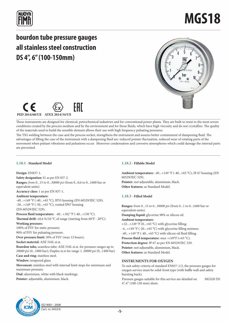
These instruments are designed for chemical, petrochemical industries and for conventional power plants. They are built to resist to the most severe
conditions created by the process medium and by the environment and for those fluids, which have high viscosity and do not crystallize. The quality
of the materials used to build the sensible element allows their use with high frequency pulsating pressures.
The TIG welding between the case and the process socket, strengthens the instrument and assures better containment of dampening fluid. The
advantages of filling the case of the instrument with a dampening fluid are: reduced pointer fluctuation, reduced wear of rotating parts of the
movement when pulsant vibrations and pulsations occur. Moreover condensation and corrosive atmospheres which could damage the internal parts
are prevented.
bourdon tube pressure gaugesall stainless steel constructionDS 4”, 6” (100-150mm)
1.18.1 - Standard Model
Design: EN837-1.
Safety designation: S1 as per EN 837-2.
Ranges: from 0...15 to 0...30000 psi (from 0...0,6 to 0...1600 bar or
equivalent units).
Accuracy class: 1 as per EN 837-1.
Ambient temperature:
-40...+149 °F (-40...+65 °C), IP55 housing (EN 60529/IEC 529);
-58...+149 °F (-50...+65 °C), vented IP67 housing
(EN 60529/IEC 529).
Process fluid temperature: -40...+302 °F (-40...+150 °C).
Thermal drift: ±0,4 %/10 °C of range (starting from 68°F - 20°C).
Working pressure:
100% of FSV for static pressure;
90% of FSV for pulsating pressure.
Over pressure limit: 30% of FSV (max 12 hours).
Socket material: AISI 316L st.st.
Bourdon tube, seamless tube: AISI 316L st.st. for pressure ranges up to
20000 psi (0...1000 bar); Duplex st.st for range ≥ 20000 psi (0...1400 bar)
Case and ring: stainless steel.
Window: tempered glass.
Movement: stainless steel with internal limit stops for minimum and
maximum pressure.
Dial: aluminium, white with black markings.
Pointer: adjustable, aluminium, black.
1.18.2 - Fillable Model
Ambient temperature: -40...+149 °F (-40...+65 °C), IP 67 housing (EN
60529/IEC 529).
Pointer: not adjustable, aluminium, black.
Other features: as Standard Model.
1.18.3 - Filled Model
Ranges: from 0...15 to 0...30000 psi (from 0...1 to 0...1600 bar or
equivalent units).
Damping liquid: glycerine 98% or silicon oil.
Ambient temperature:
+32...+149 °F (0...+65 °C) with glycerine filling;
-4...+149 °F (-20...+65 °C) with glycerine filling mixture;
-40...+149 °F (-40...+65 °C) with silicon oil fluid filling.
Process fluid temperature: max +149°F (+65 °C).
Protection degree: IP 67 as per EN 60529/IEC 529.
Pointer: not adjustable, aluminium, black.
Other features: as Standard Model.
INSTRUMENTS FOR OXYGEN
To suit safety criteria of standard EN837-1/2, the pressure gauges for
oxygen service must be solid-front type (with baffle wall and safety
bursting back).
Pressure gauges suitable for this service are detailed on MGS20 DS
4”, 6” (100-150 mm) sheet.
ISO 9001 : 2008Cert. nr. 0433/6
41M - G 1/2 A
41M - G 1/2 A
41M - G 1/2 A
41M - G 1/2 A
43M - 1/2-14 NPT
43M - 1/2-14 NPT
43M - 1/2-14 NPT
43M - 1/2-14 NPT
MGS18
◆◆
◆
◆
◆◆
◆
◆◆
◆◆
◆◆
◆ ◆ ◆◆ ◆ ◆◆ ◆ ◆
◆ ◆ ◆
◆ ◆ ◆
◆
RC
8 -
05
/14
2G1 - 2D1 -
K06 -
B - C -
E -
L21 -
L22 -
P01 -
S10 -
G11 -
ECV -
E67 -
T01 -
T32 -
E
G
E
G
C40 -
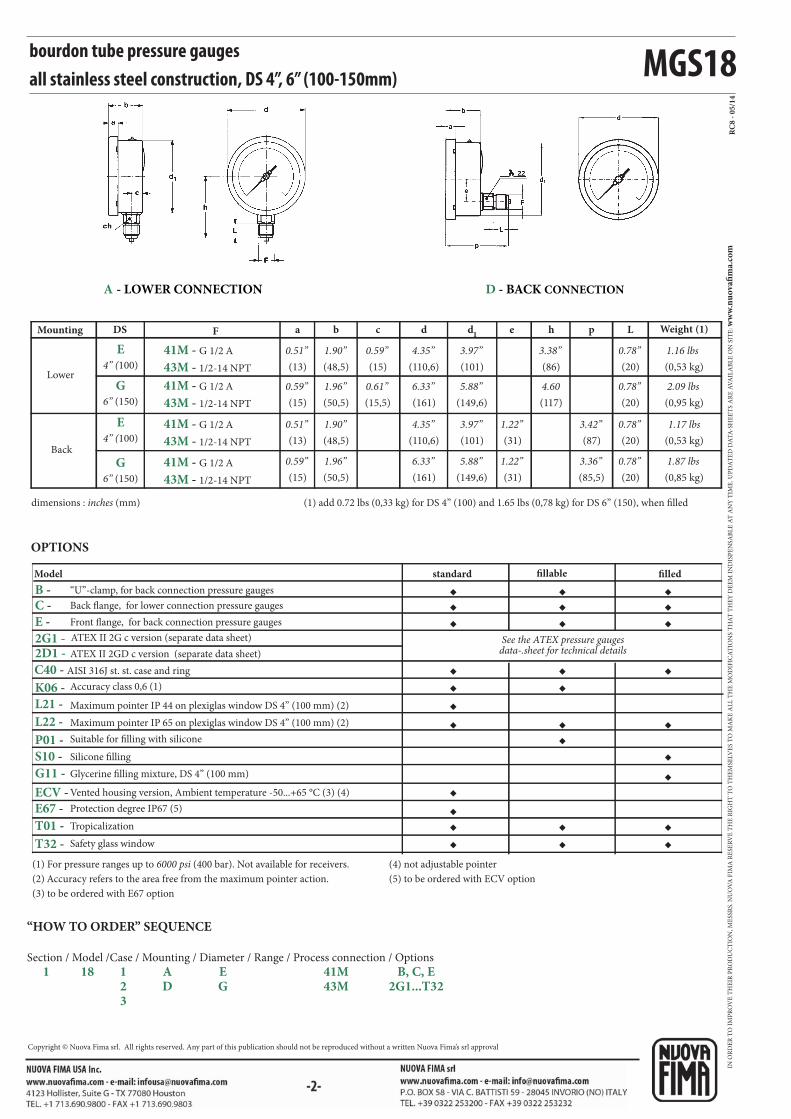
bourdon tube pressure gaugesall stainless steel construction, DS 4”, 6” (100-150mm)
“HOW TO ORDER” SEQUENCE
Section / Model /Case / Mounting / Diameter / Range / Process connection / Options
1 18 1 A E 41M B, C, E 2 D G 43M 2G1...T32 3
(1) For pressure ranges up to 6000 psi (400 bar). Not available for receivers.
(2) Accuracy refers to the area free from the maximum pointer action.
(3) to be ordered with E67 option
(4) not adjustable pointer
(5) to be ordered with ECV option
Model
Accuracy class 0,6 (1)
Maximum pointer IP 44 on plexiglas window DS 4” (100 mm) (2)
Maximum pointer IP 65 on plexiglas window DS 4” (100 mm) (2)
Suitable for filling with silicone
Silicone filling
Tropicalization
Safety glass window
OPTIONS
standard fillable filled
ATEX II 2GD c version (separate data sheet)
ATEX II 2G c version (separate data sheet) See the ATEX pressure gauges data-.sheet for technical details
“U”-clamp, for back connection pressure gauges
Back flange, for lower connection pressure gauges
Front flange, for back connection pressure gauges
dimensions : inches (mm) (1) add 0.72 lbs (0,33 kg) for DS 4” (100) and 1.65 lbs (0,78 kg) for DS 6” (150), when filled
Lower
Back
F a b c d d1
e h pMounting DS Weight (1)L
4” (100)
6” (150)
4” (100)
6” (150)
(13)
0.51”
(15)
0.59”
(13)
0.51”
(15)
0.59”
(48,5)
1.90”
(50,5)
(48,5)
(50,5)
(15)
0.59”
(15,5)
(110,6)
4.35”
(161)
(110,6)
(161)
(101)
3.97”
(149,6)
(101)
(149,6)
(31)
(31)
(86)
3.38”
(117)
(87)
(85,5)
(20)
0.78”
(20)
0.78”
(20)
0.78”
(20)
0.78”
(0,53 kg)
1.16 lbs
(0,95 kg)
2.09 lbs
(0,53 kg)
1.17 lbs
(0,85 kg)
1.87 lbs
4.605.88”6.33”0.61”1.96”
3.42”1.22”3.97”4.35”1.90”
3.36”1.22”5.88”6.33”1.96”
D - BACK CONNECTIONA - LOWER CONNECTION
AISI 316J st. st. case and ring
Glycerine filling mixture, DS 4” (100 mm)
Vented housing version, Ambient temperature -50...+65 °C (3) (4)
Protection degree IP67 (5)
IN O
RD
ER
TO
IM
PR
OV
E T
HE
IR P
RO
DU
CT
ION
, ME
SSR
S. N
UO
VA
FIM
A R
ESE
RV
E T
HE
RIG
HT
TO
TH
EM
SELV
ES
TO
MA
KE
AL
L T
HE
MO
DIF
ICA
TIO
NS
TH
AT
TH
EY
DE
EM
IN
DIS
PE
NSA
BL
E A
T A
NY
TIM
E. U
PD
AT
ED
DA
TA
-SH
EE
TS
AR
E A
VA
ILA
BL
E O
N S
ITE
: ww
w.n
uo
vafi
ma.
com
NUOVA FIMA S.p.A. - www.nuovafima.comP.O. BOX 58 - VIA C. BATTISTI 59 - 28045 INVORIO (NO) ITALYTEL. +39 0322 253200 - FAX +39 0322 253232
Copyright © Nuova Fima srl. All rights reserved. Any part of this publication should not be reproduced without a written Nuova Fima’s srl approval
-1-
MGS20
PED 2014/68/EU
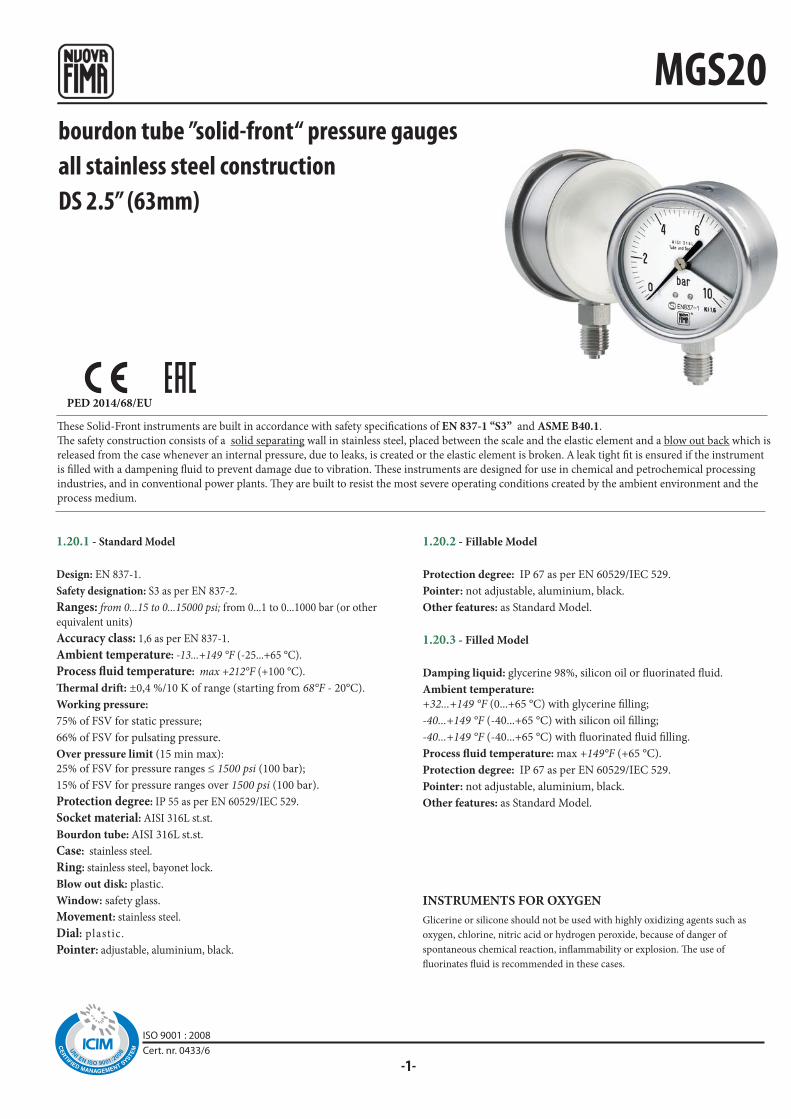
bourdon tube ”solid-front“ pressure gaugesall stainless steel constructionDS 2.5” (63mm)
These Solid-Front instruments are built in accordance with safety specifications of EN 837-1 “S3” and ASME B40.1.
The safety construction consists of a solid separating wall in stainless steel, placed between the scale and the elastic element and a blow out back which is
released from the case whenever an internal pressure, due to leaks, is created or the elastic element is broken. A leak tight fit is ensured if the instrument
is filled with a dampening fluid to prevent damage due to vibration. These instruments are designed for use in chemical and petrochemical processing
industries, and in conventional power plants. They are built to resist the most severe operating conditions created by the ambient environment and the
process medium.
1.20.1 - Standard Model
Design: EN 837-1.
Safety designation: S3 as per EN 837-2.
Ranges: from 0...15 to 0...15000 psi; from 0...1 to 0...1000 bar (or other
equivalent units)
Accuracy class: 1,6 as per EN 837-1.
Ambient temperature: -13...+149 °F (-25...+65 °C).
Process fluid temperature: max +212°F (+100 °C).
Thermal drift: ±0,4 %/10 K of range (starting from 68°F - 20°C).
Working pressure:
75% of FSV for static pressure;
66% of FSV for pulsating pressure.
Over pressure limit (15 min max):
25% of FSV for pressure ranges ≤ 1500 psi (100 bar);
15% of FSV for pressure ranges over 1500 psi (100 bar).
Protection degree: IP 55 as per EN 60529/IEC 529.
Socket material: AISI 316L st.st.
Bourdon tube: AISI 316L st.st.
Case: stainless steel.
Ring: stainless steel, bayonet lock.
Blow out disk: plastic.
Window: safety glass.
Movement: stainless steel.
Dial: plastic.
Pointer: adjustable, aluminium, black.
1.20.2 - Fillable Model
Protection degree: IP 67 as per EN 60529/IEC 529.
Pointer: not adjustable, aluminium, black.
Other features: as Standard Model.
1.20.3 - Filled Model
Damping liquid: glycerine 98%, silicon oil or fluorinated fluid.
Ambient temperature:
+32...+149 °F (0...+65 °C) with glycerine filling;
-40...+149 °F (-40...+65 °C) with silicon oil filling;
-40...+149 °F (-40...+65 °C) with fluorinated fluid filling.
Process fluid temperature: max +149°F (+65 °C).
Protection degree: IP 67 as per EN 60529/IEC 529.
Pointer: not adjustable, aluminium, black.
Other features: as Standard Model.
Glicerine or silicone should not be used with highly oxidizing agents such as
oxygen, chlorine, nitric acid or hydrogen peroxide, because of danger of
spontaneous chemical reaction, inflammability or explosion. The use of
fluorinates fluid is recommended in these cases.
INSTRUMENTS FOR OXYGEN
ISO 9001 : 2008Cert. nr. 0433/6
MGS20
(1)(2)◆◆◆
◆
◆◆
◆ ◆ ◆
F a b c d d1
h p L ch
RC5 -
03/1
4
21M - G 1/4 A
23M - 1/4-18 NPT
21M - G 1/4 A
23M - 1/4-18 NPT
P01 - P02 -
E -
S10 -
F30 -
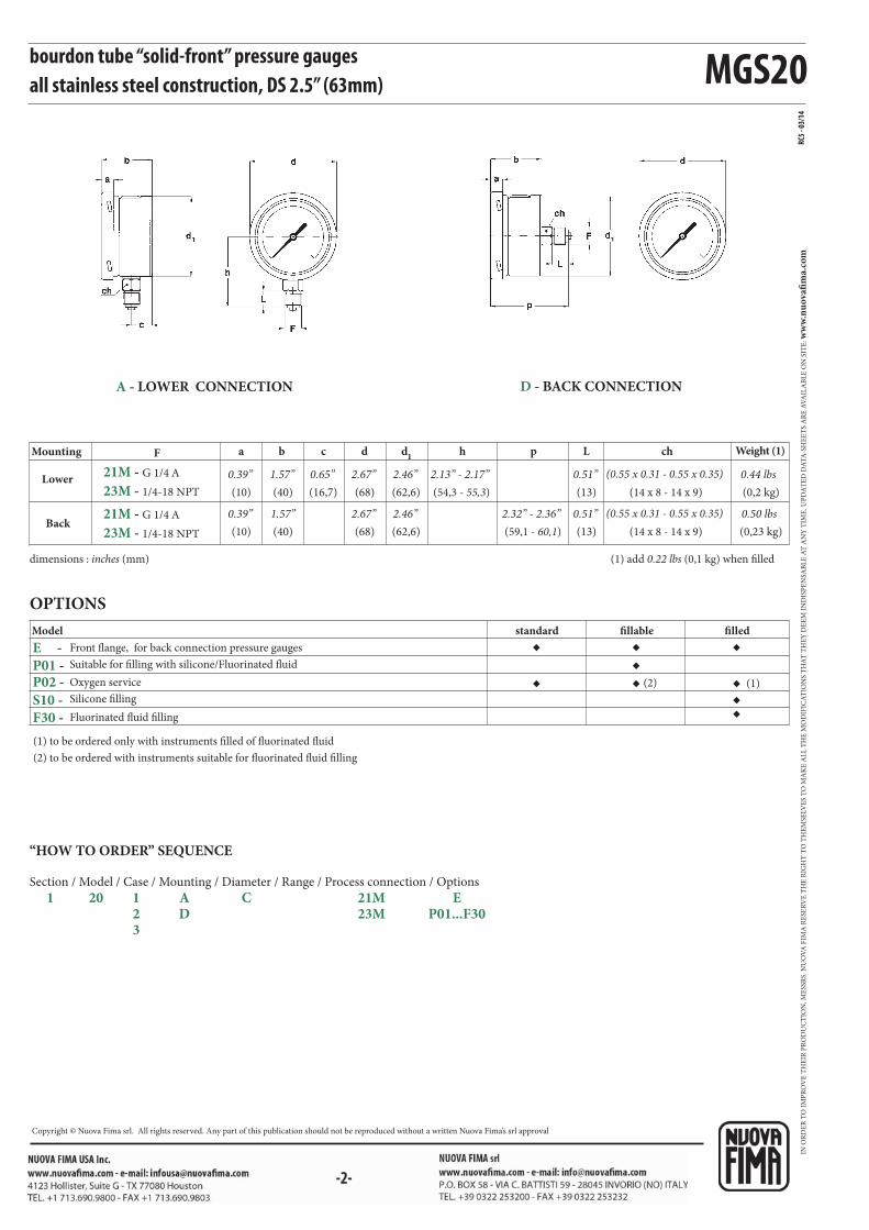
bourdon tube “solid-front” pressure gaugesall stainless steel construction, DS 2.5” (63mm)
OPTIONS
(1) to be ordered only with instruments filled of fluorinated fluid
(2) to be ordered with instruments suitable for fluorinated fluid filling
Model
Fluorinated fluid filling
Suitable for filling with silicone/Fluorinated fluid
Oxygen service
Silicone filling
Front flange, for back connection pressure gauges
(1) add 0.22 lbs (0,1 kg) when filleddimensions : inches (mm)
standard fillable filled
Lower
Mounting
Back
Weight (1)
(10)
0.39”
(10)
0.39”
(40)
1.57”
(40)
(16,7)
0.65”(68)
2.67”
(68)
(62,6)
2.46”
(62,6)
(54,3 - 55,3)
2.13” - 2.17” (13)
0.51”
(13)
0.51”
(0,2 kg)
0.44 lbs
(0,23 kg)
0.50 lbs2.46”2.67”1.57”(59,1 - 60,1)
2.32” - 2.36”
(14 x 8 - 14 x 9)
(14 x 8 - 14 x 9)
(0.55 x 0.31 - 0.55 x 0.35)
(0.55 x 0.31 - 0.55 x 0.35)
A - LOWER CONNECTION D - BACK CONNECTION
“HOW TO ORDER” SEQUENCE
Section / Model / Case / Mounting / Diameter / Range / Process connection / Options
1 20 1 A C 21M E 2 D 23M P01...F30 3
IN O
RD
ER
TO
IM
PR
OV
E T
HE
IR P
RO
DU
CT
ION
, ME
SSR
S. N
UO
VA
FIM
A R
ESE
RV
E T
HE
RIG
HT
TO
TH
EM
SELV
ES
TO
MA
KE
AL
L T
HE
MO
DIF
ICA
TIO
NS
TH
AT
TH
EY
DE
EM
IN
DIS
PE
NSA
BL
E A
T A
NY
TIM
E. U
PD
AT
ED
DA
TA
-SH
EE
TS
AR
E A
VA
ILA
BL
E O
N S
ITE
: ww
w.n
uo
vafi
ma.
com
Copyright © Nuova Fima srl. All rights reserved. Any part of this publication should not be reproduced without a written Nuova Fima’s srl approval

-1-
MGS20
PED 2014/68/UE ATEX 2014/34/UE
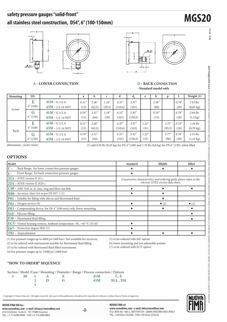
safety pressure gauges ”solid-front“all stainless steel constructionDS 4”, 6” (100-150mm)
1.20.1 - Standard Model
Design: EN837-1.
Safety designation: S3 as per EN 837-2.
Ranges: from 0...15 to 0...30000 psi (from 0...0,6 to 0...1600 bar or
equivalent units).
Accuracy class: 1 as per EN 837-1
Ambient temperature:
-40...+149 °F (-40...+65 °C), IP55 housing (IEC 529);
-58...+149 °F (-50...+65 °C), vented IP67 housing (IEC 529).
Process fluid temperature: -40...+302 °F (-40...+150 °C).
Thermal drift: ±0,4 %/10 °C of range (starting from 68°F - 20°C).
Working pressure:
100% of FSV for static pressure;
90% of FSV for pulsating pressure.
Over pressure limit: 30% of FSV (max 12 hours).
Socket material: AISI 316L st.st.
Bourdon tube, seamless tube: AISI 316L st.st. for pressure ranges up to
20000 psi (0...1000 bar); Duplex st.st for range ≥ 20000 psi (0...1400 bar)
Case: stainless steel.
Ring: stainless steel, bayonet lock.
Blow out disk: stainless steel.Window: safety glass (with external zero adjustement on request).
Movement: stainless steel with internal limit stops.
Dial: aluminium, white with black markings.
Pointer: adjustable, aluminium, black.
1.20.2 - Fillable Model - Lower connection only
Ambient temperature: -40...+149 °F (-40...+65 °C), IP 67 housing
(IEC 529).
Pointer: not adjustable, aluminium, black.
Other features: as Standard Model.
1.20.3 - Filled Model - Lower connection only
Ranges: from 0...15 to 0...30000 psi (from 0...1 to 0...1600 bar or
equivalent units)
Damping liquid: glycerine 98%, silicon oil or fluorinated fluid.
Ambient temperature:
+32...+149 °F (0...+65 °C) with glycerine filling;
-40...+149 °F (-40...+65 °C) with silicon oil filling and fluorinated
fluid filling.
Process fluid temperature: max +149°F (+65 °C).
Protection degree: IP 67 as per IEC 529.
Pointer: not adjustable, aluminium, black.
Other features: as Standard Model.
These instruments are built in conformity with the construction and safety specifications of EN 837-1/S3 e ASME B40.1.
In case of leaks or break of the elastic element, the operator is protected by a solid separating wall placed on the front of the instrument and by the
blow out back. They are usually used in the food, process, pharmaceutical, petrochemical industries and in conventional and nuclear power plants.
The TIG welding between the case and the process socket, strengthens the instrument and assures a better tight in case of dampening fluid. The
advantages of filling the case of the instrument with a dampening fluid are: reduced pointer fluctuation, reduced wear of rotating parts of the
movement when pulsant vibrations and pulsations occur. Moreover condensation and corrosive atmospheres which could damage the internal parts
are prevented.
INSTRUMENTS FOR OXYGEN - Glicerine or silicone should not be
used with highly oxidizing agents such as oxygen, chlorine, nitric acid or
hydrogen peroxide, because of danger of spontaneous chemical reaction,
inflammability or explosion. The use of fluorinates fluid is recommended in these
cases.
ISO 9001 : 2008Cert. nr. 0433/6
MGS20
◆
◆
◆
◆
◆
◆◆
◆◆
◆
◆◆ (2)
◆
◆
◆
◆
◆
◆
◆ (3)
◆
◆
◆
◆
F a b c d d1
e h p L
RC
6 -
05
/14
E
G
E
G
41M - G 1/2 A
41M - G 1/2 A
41M - G 1/2 A
41M - G 1/2 A
43M - 1/2-14 NPT
43M - 1/2-14 NPT
43M - 1/2-14 NPT
43M - 1/2-14 NPT
2D1 -
C40 -
K06 -
C -
E -
2G1 -
P01 -
P02 -
P03 -
S10 -
F30 -
ECV-
E67-
T01 -
safety pressure gauges “solid-front” all stainless steel construction, DS4”, 6” (100-150mm)
Model
AISI 316L st. st. case, ring and blow out disk
Suitable for filling with silicon and fluorinated fluid
Oxygen service (4)
Silicone filling
Tropicalization
Accuracy class: 0,6 as per EN 837-1 (1)
OPTIONS
Fluorinated fluid filling
Compensating device, for DS 4” (100 mm) only, lower mounting
(1) For pressure ranges up to 6000 psi (400 bar). Not available for receivers.
(2) to be ordered with instruments suitable for fluorinated fluid filling
(3) to be ordered with fluorinated fluid filled instruments
(4) For pressure ranges up to 15000 psi (1000 bar)
(5) to be ordered with E67 option
(6) lower mounting and not adjustable pointer
(7) to be ordered with ECV option
ATEX version II 2GD c
ATEX version II 2G c Constructive characteristics and ordering guide please refere to the relevant ATEX version data sheet.
Back flange, for lower connection pressure gauges
Front flange, for back connection pressure gauges
standard fillable filled
Lower
Back
dimensions : inches (mm) (1) add 0.95 lbs (0,43 kg) for DS 4” (100) and 1.76 lbs (0,8 kg) for DS 6” (150), when filled
Mounting DS Weight (1)
(13)
0.51”
(15)
0.59”
(13)
0.51”
(15)
0.59”
(62,5)
2.46”
(64)
(62,5)
(64)
(29,5)
1.16”
(30)
(110,6)
4.35”
(161)
(110,6)
(161)
(101)
3.97”
(150,5)
(101)
(150,5)
(31)
(31)
(86)
3.38”
(15)
(95,5)
(96)
(20)
0.78”
(20)
0.78”
(20)
0.78”
(20)
0.78”
(0,65 kg)
1.43 lbs
(1,2 kg)
2.64 lbs
(0,70 kg)
1.54 lbs
(1,15 kg)
2.53 lbs
0.59”5.92”6.33”1.18”2.51”
3.75”1.22”3.97”4.35”2.46”
3.77”1.22”5.92”6.33”2.51”
4” (100)
6” (150)
4” (100)
6” (150)
D - BACK CONNECTION
- Standard model only
A - LOWER CONNECTION
“HOW TO ORDER” SEQUENCE
Section / Model /Case / Mounting / Diameter / Range / Process connection / Options
1 20 1 A E 41M C, E 2 D G 43M 2G1...T01 3
Vented housing version, Ambient temperature -50...+65 °C (5) (6)
Protection degree IP67 (7)
IN O
RD
ER
TO
IM
PR
OV
E T
HE
IR P
RO
DU
CT
ION
, ME
SSR
S. N
UO
VA
FIM
A R
ESE
RV
E T
HE
RIG
HT
TO
TH
EM
SELV
ES
TO
MA
KE
AL
L T
HE
MO
DIF
ICA
TIO
NS
TH
AT
TH
EY
DE
EM
IN
DIS
PE
NSA
BL
E A
T A
NY
TIM
E. U
PD
AT
ED
DA
TA
-SH
EE
TS
AR
E A
VA
ILA
BL
E O
N S
ITE
: ww
w.n
uo
vafi
ma.
com
Copyright © Nuova Fima srl. All rights reserved. Any part of this publication should not be reproduced without a written Nuova Fima’s srl approval
-1-
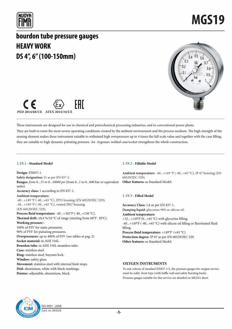
MGS19
PED 2014/68/UE ATEX 2014/34/UE
bourdon tube pressure gaugesHEAVY WORKDS 4”, 6” (100-150mm)
These instruments are designed for use in chemical and petrochemical processing industries, and in conventional power plants.
They are built to resist the most severe operating conditions created by the ambient environment and the process medium. The high strength of the
sensing element makes these instrument suitable to withstand high overpressure up to 4 times the full scale value and together with the case filling,
they are suitable to high dynamic pulsating pressure. An Argonarc welded case/socket strengthens the whole construction.
1.19.2 - Fillable Model
Ambient temperature: -40...+149 °F (-40...+65 °C), IP 67 housing (EN
60529/IEC 529).
Other features: as Standard Model.
1.19.3 - Filled Model
Accuracy Class: 1,6 as per EN 837-1.
Damping liquid: gliycerine 98% or silicon oil.
Ambient temperature:
+32...+149°F (0...+65 °C) with glycerine filling;
-40...+149°F (-40...+65 °C) with silicon oil filling or fluorinated fluid
filling.
Process fluid temperature: +149°F (+65 °C).
Protection degree: IP 67 as per EN 60529/IEC 529.
Other features: as Standard Model.
OXYGEN INSTRUMENTS
To suit criteria of standard EN837-1/2, the pressure gauges for oxygen service
must be solid- front type (with baffle wall and safety bursting back).
Pressure gauges suitable for this service are detailed on MGS21 sheet.
1.19.1 - Standard Model
Design: EN837-1.
Safety designation: S1 as per EN 837-2.
Ranges: from 0...15 to 0...10000 psi (from 0...1 to 0...600 bar or equivalent
units).
Accuracy class: 1 according to EN 837-1.
Ambient temperature:
-40...+149 °F (-40...+65 °C), IP55 housing (EN 60529/IEC 529);
-58...+149 °F (-50...+65 °C), vented IP67 housing
(EN 60529/IEC 529).
Process fluid temperature: -40...+302°F (-40...+150 °C).
Thermal drift: ±0,4 %/10 °C of range (starting from 68°F- 20°C).
Working pressure :
100% of FSV for static pressures;
90% of FSV for pulsating pressures.
Overpressures: up to 400% of FSV (see tables at pag. 2)
Socket material: in AISI 316L.
Bourdon tube: in AISI 316L steamless tube.
Case: stainless steel.
Ring: stainless steel, bayonet lock.
Window: safety glass.
Movement: stainless steel with internal limit stops.
Dial: aluminium, white with black markings.
Pointer: adjustable, aluminium, black.
ISO 9001 : 2008Cert. nr. 0433/6
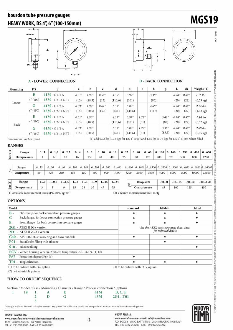
MGS19
◆
◆
◆◆
◆◆
◆
◆
◆ ◆ ◆◆ ◆ ◆◆ ◆ ◆
◆
F a b c d d1
e h p LL ch
RC
7 -
03
/14
41M - G 1/2 A
43M - 1/2-14 NPT
41M - G 1/2 A
43M - 1/2-14 NPT
41M - G 1/2 A
43M - 1/2-14 NPT
41M - G 1/2 A
43M - 1/2-14 NPT
E
G
E
G
2G1 - 2D1 -
C40 -
B - C -
E -
P01 -
S10 -
ECV -
E67 -
T01 -
4 6 10 16 25 40 48 75 80 120 200 320 500 800 1200
60 120 240 400 480 600 900 1000 1200 2000 3000 4000 6000 8000 10000 15000
-30...0 -30...15 -30...30 -30...150-1...0 -1...0,6 -1...1,5 -1...3 -1...5 -1...9 -1...15 -1...24
45 100 125 4503 5 9 15 23 39 47 75
-2-
bourdon tube pressure gaugesHEAVY WORK, DS 4”, 6” (100-150mm)
dimensions : inches (mm) (1) add 0.72 lbs (0,33 kg) for DS 4” (100) and 1.65 lbs (0,78 kg) for DS 6” (150), when filled
AISI 316L st. st. case, ring and blow out disk
Model
Suitable for filling with silicone
Silicone filling
Tropicalization
OPTIONS
standard fillable filled
ATEX II 2GD c version
ATEX II 2G c version See the ATEX pressure gauges data-.sheet for technical details
“U”-clamp, for back connection pressure gauges
Back flange, for lower connection pressure gauges
Front flange, for back connection pressure gauges
Lower
Back
Mounting DS Weight (1)
4” (100)
6” (150)
4” (100)
6” (150)
(13)
0.51”
(15)
0.59”
(13)
0.51”
(15)
0.59”
(48,5)
1.90”
(50,5)
(48,5)
(50,5)
(15)
0.59”
(15,5)
(110,6)
4.35”
(161)
(110,6)
(161)
(101)
3.97”
(149,6)
(101)
(149,6)
(31)
(31)
(86)
3.38”
(117)
(87)
(85,5)
(20)
0.78”
(20)
0.78”
(20)
0.78”
(20)
0.78”
(0,53 kg)
1.16 lbs
(1,02 kg)
2.24 lbs
(0,52 kg)
1.14 lbs
(0,95 kg)
2.09 lbs
4.60”5.88”6.33”0.61”1.98”
3.42”1.22”3.97”4.35”1.90”
3.36”1.22”5.88”6.33”1.98”
A - LOWER CONNECTION D - BACK CONNECTION
“HOW TO ORDER” SEQUENCE
Section / Model /Case / Mounting / Diameter / Range / Process connection / Options
1 19 1 A E 41M B, C, E 2 D G 43M 2G1...T01 3
(22)
0.87”
(22)
0.87”
(22)
0.87”
(22)
0.87”
Vented housing version, Ambient temperature -50...+65 °C (1) (2)
Protection degree IP67 (3)
(1) to be ordered with E67 option
(2) not adjustable pointer
(3) to be ordered with ECV option
(1) Available measurement units kPa, MPa, kg/cm2 (2) Vacuum measurement unit: InHg
RANGES
Ranges
Ranges 0...1 0...1,6 0...2,5 0...4 0...6 0...10 0...16 0...25 0...40 0...60 0...100 0...160 0...250 0...400 0...600
0...400 0...600 0...1000 0...1500 0...2000 0...3000 0...4000 0...6000 0...100000...15 0...30 0...60 0...100 0...160 0...200 0...300
Overpressure
Overpressure
Ranges
Overpressure
Ranges (2)
Overpressure
bar
(1
)b
ar (
1)
psi
psi
IN O
RD
ER
TO
IM
PR
OV
E T
HE
IR P
RO
DU
CT
ION
, ME
SSR
S. N
UO
VA
FIM
A R
ESE
RV
E T
HE
RIG
HT
TO
TH
EM
SELV
ES
TO
MA
KE
AL
L T
HE
MO
DIF
ICA
TIO
NS
TH
AT
TH
EY
DE
EM
IN
DIS
PE
NSA
BL
E A
T A
NY
TIM
E. U
PD
AT
ED
DA
TA
-SH
EE
TS
AR
E A
VA
ILA
BL
E O
N S
ITE
: ww
w.n
uo
vafi
ma.
com
Copyright © Nuova Fima srl. All rights reserved. Any part of this publication should not be reproduced without a written Nuova Fima’s srl approval

-1-
MGS21
PED 2014/68/UE ATEX 2014/34/UE
bourdon tube “solid-front” pressure gaugesHEAVY WORKDS 4”, 6” (100-150mm)
These instruments are designed for use in chemical and petrochemical processing industries, and in conventional power plants.They are built to
resist the most severe operating conditions created by the ambient environment and the process medium. The high strength of the sensing element
makes these instrument suitable to withstand high overpressure up to 4 times the full scale value and together with the case filling, they are suitable
to high dynamic pulsating pressure. An Argonarc welded case/socket strengthens the whole construction. The solid-front version of these
instruments is built in accordance with safety specifications of EN 837-1 and ASME B40.1. The safety construction consists of a solid separating
wall in stainless steel, placed between the dial and the elastic element and a blow out back which is released from the case whenever an internal
pressure, due to leaks, is created or the elastic element is broken.
1.21.1 - Standard Model
Design: EN 837-1.
Safety designation: S3 as per EN 837-2.
Campi scala: from 0...15 to 10000 psi; (from 0...1 to 0...600 bar or
other equivalent units)
Accuracy class: 1 as per EN 837-1.
Ambient temperature: -40...+149 °F (-40...+65 °C), IP55 housing (EN 60529/IEC 529);
-58...+149 °F (-50...+65 °C), vented IP67 housing
(EN 60529/IEC 529).
Process fluid temperature: -40...+302°F (-40...+150 °C).
Thermal drift: ±0,4 %/10 °C of range (starting from 68°F - 20°C).
Working pressure:
100% del FSV for static pressure;
90% del FSV for pulsating pressure.
Overpressure limit: 400% of FSV (see table at pag. 2)
Socket material: AISI 316L st.st.
Bourdon tube: AISI 316L st.st. steamless tube
Case: stainless steel.
Ring: stainless steel, bayonet lock.
Blow out disc: stainless steel.
Window: safety glass.
Movement: stainless steel with internal limit stop.
Dial: aluminium, white with black markings
Pointer: adjustable, aluminium, black.
1.21.2 - Fillable Model - Lower connection only
Ambient temperature: -40...+149 °F (-40...+65 °C), IP 67 housing (EN
60529/IEC 529).
Other features: as Standard Model.
1.21.3 - Filled Model - Lower connection only
Accuracy class: 1,6 as per EN 837-1.
Damping liquid: glycerine 98%, silicon oil or fluorinated fluid.
Ambient temperature:
+32...+149°F (0...+65 °C) with glycerine filling;
-40...+149°F (-40...+65 °C ) with silicon oil filling or fluorinated fluid
filling.
Process fluid temperature: max +149°F (+65 °C).
Protection degree: IP 67 as per EN 60529/IEC 529.
Window: tempered glass.
Other features: as Standard Model.
Glycerine and silicon oil should not be used with highly oxydizing
agents as oxygen, chlorine, nitric acid or hydrogrn peroxide because of
danger of spontaneous chemical reaction, inflammability or explosion.
The use of fluorinates fluid is recommended in these cases.
OXYGEN INSTRUMENTS
ISO 9001 : 2008Cert. nr. 0433/6

◆
◆
◆
◆
◆◆
◆◆
◆ (1)
◆
◆◆
◆
◆
◆
◆
◆ (2)
◆
◆
◆
◆
MGS21
F a b c d d1
e h p L
RC7
- 05/
14
41M - G 1/2 A
43M - 1/2-14 NPT
41M - G 1/2 A
43M - 1/2-14 NPT
41M - G 1/2 A
43M - 1/2-14 NPT
41M - G 1/2 A
43M - 1/2-14 NPT
E
G
E
G
2D1 -
C40 -
P01 -
C -
E -
2G1 -
P02 -
P03 -
S10 -
F30 -
E67 -
ECV -
T01 -
4 6 10 16 25 40 48 75 80 120 200 320 500 800 1200
60 120 240 400 480 600 900 1000 1200 2000 3000 4000 6000 8000 10000 15000
-30...0 -30...15 -30...30 -30...150-1...0 -1...0,6 -1...1,5 -1...3 -1...5 -1...9 -1...15 -1...24
45 100 125 4503 5 9 15 23 39 47 75
-2-
bourdon tube “solid-front” pressure gauges HEAVY WORK, DS 4”, 6” (100-150mm)
dimensions : inches (mm)
Model
AISI 316L st. st. case, ring and blow out disc
Suitable for filling with silicone/fluorinated fluid
Oxygen service
Silicone filling
Tropicalization
Fluorinated fluid filling
Compensating device, for DS 4” (100 mm) and lower mounting only
(1) to be ordered with instruments suitable for fluorinated fluid filling (2) to be ordered with fluorinated fluid filled instruments
(3) to be ordered with E67 option
(4) lower mounting and not adjustable pointer
(5) to be ordered with ECV option
ATEX II 2GD c version
ATEX II 2G c version See the ATEX pressure gauges data-sheet for technical details
Back flange, for lower connection pressure gauges
Front flange, for back connection pressure gauges
standard fillable filled
Lower
Back
Mounting DS Weight
4” (100)
6” (150)
4” (100)
6” (150)
(13)
0.51”
(15)
0.59”
(13)
0.51”
(15)
0.59”
(62,5)
2.46”
(64)
(62,5)
(64)
(29,5)
1.16”
(30)
(110,6)
4.35”
(161)
(110,6)
(161)
(101)
3.97”
(150,5)
(101)
(150,5)
(31)
(31)
(86)
3.38”
(117)
(95,5)
(96)
(20)
0.78”
(20)
0.78”
(20)
0.78”
(20)
0.78”
(0,65 kg)
1.43 lbs
(1,2 kg)
2.64 lbs
(0,70 kg)
1.54 lbs
(1,15 kg)
2.53 lbs
4.60”5.92”6.33”1.18”2.51”
3.75”1.22”3.97”4.35”2.46”
3.77”1.22”5.92”6.33”2.51”
A - LOWER CONNECTION D - BACK CONNECTION
“HOW TO ORDER” SEQUENCE
Section / Model /Case / Mounting / Diameter / Range / Process connection / Options
1 21 1 A E 41M C, E
2 D G 43M 2G1...T01
3
(1) add 0.95 lbs (0,43 kg) for DS 4” (100) and 1.76 lbs (0,8 kg) for DS 6” (150), when filled
Vented housing version, Ambient temperature -50...+65 °C (3) (4)
Protection degree IP67 (5)
(1) Available measurement units kPa, MPa, kg/cm2 (2) Vacuum measurement unit: InHg
Ranges
Ranges 0...1 0...1,6 0...2,5 0...4 0...6 0...10 0...16 0...25 0...40 0...60 0...100 0...160 0...250 0...400 0...600
0...400 0...600 0...1000 0...1500 0...2000 0...3000 0...4000 0...6000 0...100000...15 0...30 0...60 0...100 0...160 0...200 0...300
Overpressure
Overpressure
Ranges
Overpressure
Ranges (2)
Overpressure
bar
(1
)b
ar (
1)
psi
psi
IN O
RD
ER
TO
IM
PR
OV
E T
HE
IR P
RO
DU
CT
ION
, ME
SSR
S. N
UO
VA
FIM
A R
ESE
RV
E T
HE
RIG
HT
TO
TH
EM
SELV
ES
TO
MA
KE
AL
L T
HE
MO
DIF
ICA
TIO
NS
TH
AT
TH
EY
DE
EM
IN
DIS
PE
NSA
BL
E A
T A
NY
TIM
E. U
PD
AT
ED
DA
TA
-SH
EE
TS
AR
E A
VA
ILA
BL
E O
N S
ITE
: ww
w.n
uo
vafi
ma.
com
NUOVA FIMA S.p.A. - www.nuovafima.comP.O. BOX 58 - VIA C. BATTISTI 59 - 28045 INVORIO (NO) ITALYTEL. +39 0322 253200 - FAX +39 0322 253232
Copyright © Nuova Fima srl. All rights reserved. Any part of this publication should not be reproduced without a written Nuova Fima’s srl approval

-1-
MGS22
PED 2014/68/UE
safety pressure gauges ”solid-front“all stainless steel constructionfor high pressures,DS 4”, 6” (100-150mm)
1.22.1 - Standard Model
Design: S3 as per EN 837-2.
Ranges: 0...2500, 0...3000 and 0...4000 bar;
0...30000, 0...40000 and 0...60000 psi/bar.
Accuracy class: ±1% of F.S.V.
Ambient temperature: -40...+149 °F (-40...+65 °C).
Process fluid temperature: -40...+302 °F (-40...+150 °C).
Thermal drift: ±0,4 %/10 °C of range (starting from 68°F - 20°C).
Working pressure:
75% of FSV for static pressure;
66% of FSV for pulsating pressure.
Over pressure limit: 10% of FSV (temporary).
Protection degree: IP 55 as per IEC 529.
Socket material: AISI 316L st.st.
Bourdon tube: duplex st.st. seamless tube.
Case: stainless steel.
Ring: stainless steel, bayonet lock.
Blow out disk: stainless steel.
Window: safety glass.
Movement: stainless steel with internal limit stops.
Dial: aluminium, white with black markings.
Pointer: adjustable, aluminium, black.
1.22.2 - Fillable Model
Protection degree: IP 67 as per IEC 529.
Pointer: not adjustable, aluminium, black.
Other features: as Standard Model.
1.22.3 - Filled Model
Damping liquid: glycerine 98%, silicon oil.
Ambient temperature:
+32...+149 °F (0...+65 °C) with glycerine filling;
-40...+149 °F (-40...+65 °C) with silicon oil filling.
Process fluid temperature: max +149°F (+65 °C).
Protection degree: IP 67 as per IEC 529.
Pointer: not adjustable, aluminium, black.
Other features: as Standard Model.
These instruments are built in conformity with the construction and safety specifications of EN 837-1/S3 e ASME B40.1.
In case of leaks or break of the elastic element, the operator is protected by a solid separating wall placed on the front of the instrument and by the
blow out back. They are mainly used on high pressure water jet technology like water cutting machines, hydro blasting pumps and turbines,
hydrodemolition. The TIG welding between the case and the process socket, strengthens the instrument and assures a better tight in case of
dampening fluid. The advantages of filling the case of the instrument with a dampening fluid are: reduced pointer fluctuation, reduced wear of
rotating parts of the movement when pulsant vibrations and pulsations occur. Moreover condensation and corrosive atmospheres which could
damage the internal parts are prevented.
ISO 9001 : 2008Cert. nr. 0433/6
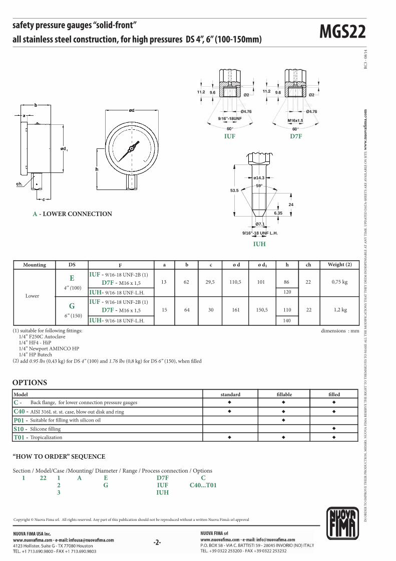
MGS22
◆
◆
◆◆◆
◆
◆◆
◆◆
◆
RC
3 -
08
/14
C40 -
C -
P01 -
S10 -
T01 -
F
D7F - M16 x 1,5
IUF - 9/16-18 UNF-2B (1)
IUH- 9/16-18 UNF-L.H.
D7F - M16 x 1,5
IUF - 9/16-18 UNF-2B (1)
IUH- 9/16-18 UNF-L.H.
a b c ø d ø d1 h ch
Ø7.1
9/16"-18 UNF L.H.
53.5
6.35
24
59°
ø14.3
IUF
IUH
D7F
-2-
safety pressure gauges “solid-front” all stainless steel construction, for high pressures DS 4”, 6” (100-150mm)
A - LOWER CONNECTION
Model
AISI 316L st. st. case, blow out disk and ring
Suitable for filling with silicon oil
Silicone filling
Tropicalization
OPTIONS
Back flange, for lower connection pressure gauges
standard fillable filled
“HOW TO ORDER” SEQUENCE
Section / Model/Case /Mounting/ Diameter / Range / Process connection / Options
1 22 1 A E D7F C 2 G IUF C40...T01 3 IUH
dimensions : mm
Lower
Mounting
E
G
4” (100)
6” (150)
13
15
62
64
29,5
30
110,5
161
101
150,5
86
110
Weight (2)
0,75 kg
1,2 kg
22
22
DS
(1) suitable for following fittings: 1/4” F250C Autoclave 1/4” HF4 - HiP 1/4” Newport AMINCO HP 1/4” HP Butech(2) add 0.95 lbs (0,43 kg) for DS 4” (100) and 1.76 lbs (0,8 kg) for DS 6” (150), when filled
120
140
IN O
RD
ER
TO
IM
PR
OV
E T
HE
IR P
RO
DU
CT
ION
, ME
SSR
S. N
UO
VA
FIM
A R
ESE
RV
E T
HE
RIG
HT
TO
TH
EM
SELV
ES
TO
MA
KE
AL
L T
HE
MO
DIF
ICA
TIO
NS
TH
AT
TH
EY
DE
EM
IN
DIS
PE
NSA
BL
E A
T A
NY
TIM
E. U
PD
AT
ED
DA
TA
-SH
EE
TS
AR
E A
VA
ILA
BL
E O
N S
ITE
: ww
w.n
uo
vafi
ma.
com
Copyright © Nuova Fima srl. All rights reserved. Any part of this publication should not be reproduced without a written Nuova Fima’s srl approval

-1-
MGS44
PED 2014/68/EU ATEX 2014/34/EU
ISO 9001 : 2008Cert. nr. 0433/6
bourdon tube pressure gaugesstainless steel constructionDS 4” (100mm)
1.44.2 - Fillable Model
Design: EN 837-1.
Safety designation: S1 as per EN 837-2.
Ranges: from 0...15 to 0...6000 psi (from 0...1 to 0...400 bar or
equivalent units).
Accuracy class: 1,6 as per EN 837-1.
Ambient temperature: -13...+149°F (-25...+65 °C).
Process fluid temperature: -13...+212 °F (-25...+100 °C).
Thermal drift: max ±0,4 %/10 °C of scale range (starting from +68°F- 20°C).
Working pressure:
75% of FSV for static pressure.
66% of FSV for pulsating pressure.
Over pressure limit (15 min max):
25% of FSV for pressure ranges ≤ 1500 psi (100 bar);
15% of FSV for pressure ranges over 1500 psi (100 bar).
Protection degree: IP 67 as per IEC 529.
Socket material: AISI 316L st.st.
Elastic element: AISI 316L st.st.
Case: stainless steel
Ring: stainless stees, crimped
Window: tempered glass.
Movement: copper and stainless steel.
Dial: aluminium, white with black markings, or with double red and
black markings.
Pointer: not adjustable, aluminium,black.
1.44.3 - Filled Model
Damping liquid: glycerine 98%, silicon oil.
Ambient temperature:
+32...+149 °F (0...+65 °C) with glycerine filling;
-40...+149 °F (-40...+65 °C) with silicon oil filling.
Process fluid temperature: max +149°F (+65 °C).
Other features: as fillable model.
They are designed for industrial use. They are suitable for tough working conditions and for aggressive fluids. An exclusive Laser calibration
procedure features each instrument and allows a very precise accuracy. Filling the case with dampening liquid prevents any condensation and the
entrance of corrosive atmosphere increasing its resistance to vibrations and to pulsating pressures.
ISO 9001 : 2008Cert. nr. 0433/6
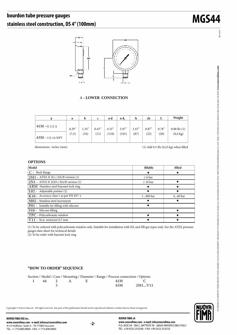
ø d1F a b c ø d h Lch
RC4 -
01/1
5
41M - G 1/2 A
43M - 1/2-14 NPT
C - 2M1 - 2N1 -
K10 -
M02 -
MGS44
P01 - S10 -
TPC - V11 -
ARM -
L02 -
◆ ◆
◆
◆ ◆◆
◆◆ ◆◆ ◆
◆ ◆◆ ◆
bourdon tube pressure gaugesstainless steel construction, DS 4” (100mm)
dimensions : inches (mm) (1) Add 0.5 Ibs (0,23 kg) when filled
Weight
(7,5)
0.29”(34)
1.34”(11)
0.43”(110)
4.33”(101)
3.97”(87)
3.43”(20)
0.78”(0,4 kg)
0.88 lbs (1)(22)
0.87”
Back flange
OPTIONS
A - LOWER CONNECTION
“HOW TO ORDER” SEQUENCE
Section / Model / Case / Mounting / Diameter / Range / Process connection / Options
1 44 2 A E 41M C 3 43M 2M1...V11
ATEX II 2GD c IIA/B version (1)
ATEX II 2G c IIA/B version (1)
Model fillable filled
Accuracy class 1 as per EN 837-1. 1...400 bar 4...40 bar
≥ 10 bar
≤ 6 bar
Stainless steel movement
Suitable for filling with silicone
Silicone filling
Polycarbonate window
St.st. restrictor 0,7 mm
(1) To be ordered with polycarbonate window only. Suitable for installation with IIA and IIB gas types only. See the ATEX pressure
gauges data-sheet for technical details
(2) To be order with bayonet lock ring
Stainless steel bayonet lock ring
Adjustable pointer (2)
IN O
RD
ER
TO
IM
PR
OV
E T
HE
IR P
RO
DU
CT
ION
, ME
SSR
S. N
UO
VA
FIM
A R
ESE
RV
E T
HE
RIG
HT
TO
TH
EM
SELV
ES
TO
MA
KE
AL
L T
HE
MO
DIF
ICA
TIO
NS
TH
AT
TH
EY
DE
EM
IN
DIS
PE
NSA
BL
E A
T A
NY
TIM
E. U
PD
AT
ED
DA
TA
-SH
EE
TS
AR
E A
VA
ILA
BL
E O
N S
ITE
: ww
w.n
uo
vafi
ma.
com
Copyright © Nuova Fima srl. All rights reserved. Any part of this publication should not be reproduced without a written Nuova Fima’s srl approval

-1-
MGS36
PED 2014/68/UE ATEX 2014/34/UE
1.36.1 - Standard Model
Design: EN 837-1, ISO 15156-3.
Safety designation: S1 as per EN 837-2.
Ranges: from 0...15 to 0…10000 psi (from 0...1 to 0...600 bar or equivalent units).
Accuracy class: 1 as per EN 837-1.
Ambient temperature:
-40...+149 °F (-40...+65 °C), IP55 housing (EN 60529/IEC 529);
-58...+149 °F (-50...+65 °C), vented IP67 housing
(EN 60529/IEC 529).Process fluid temperature: -40...+302 °F (-40...+150 °C).
Thermal drift: ±0,4 %/10 °C of range (starting from 68°F - 20°C).
Working pressure:
100% of FSV for static pressure;
90% of FSV for pulsating pressure.
Over pressure limit: 30% of FSV (max 12 hours).
Socket material: AISI 316L st.st. or Monel 400.
Bourdon tube: Monel 400 seamless tube.
Leak test: Helium Test leak Search (max 1x10⁻⁶ mbar x l x s-1)
Case: stainless steel.
Ring: stainless steel, bayonet lock.
Window: tempered glass (with external zero adjustement on request).
Movement: stainless steel with internal limit stops.
Dial: aluminium, white with black markings.
Pointer: adjustable, aluminium, black.
1.36.2 - Fillable Model
Ambient temperature: -40...+149 °F (-40...+65 °C), IP 67 housing (EN
60529/IEC 529).Other features: as Standard Model.
1.36.3 - Filled Model
Damping liquid: glycerine 98% or silicon oil.
Ambient temperature:
+32...+149 °F (0...+65 °C) with glycerine filling;
-4...+149 °F (-20...+65 °C) with glycerine filling mixture;
-40...+149 °F (-40...+65 °C) with silicon oil fluid filling.Process fluid temperature: max +149°F (+65 °C).
Protection degree: IP 67 as per EN 60529/IEC 529.
Other features: as Standard Model.
These instruments are designed for petrochemical industry. They are built to resist to the most severe conditions created by H2S, by the environment
and for those fluids, which have high viscosity and do not crystallize. The quality of the materials used to build the sensible element allows their use
with high frequency pulsating pressures. The TIG welding between the case and the process socket, strengthens the instrument and assures a better
tight in case of dampening fluid. The advantages of filling the case of the instrument with a dampening fluid are: reduced pointer fluctuation,
reduced wear of rotating parts of the movement when pulsant vibrations and pulsations occur. Moreover condensation and corrosive atmospheres
which could damage the internal
bourdon tube pressure gaugesNACE MR0103/MR0175 - ISO 15156-3 version DS 4”, 6” (100-150mm)
ISO 9001 : 2008Cert. nr. 0433/6
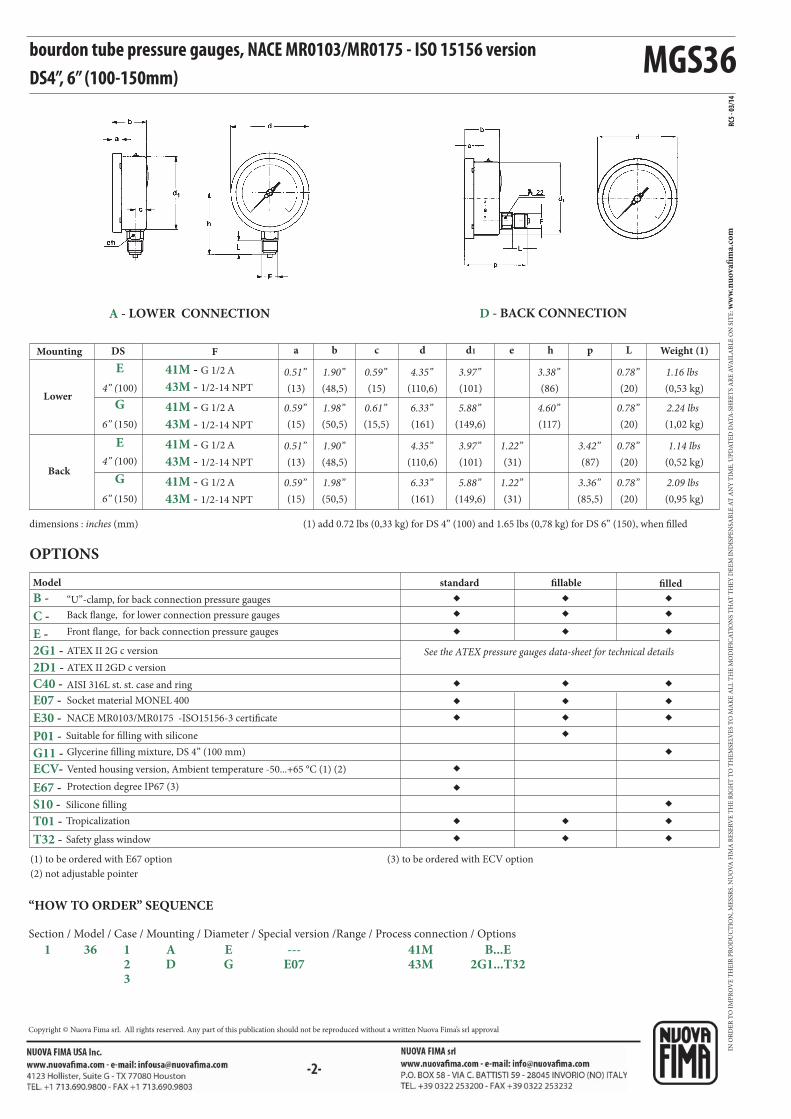
MGS36
◆◆
◆
◆
◆
◆
◆
◆◆◆
◆ ◆ ◆
◆ ◆ ◆
◆
◆ ◆ ◆
◆◆◆
◆◆◆
◆◆◆
RC5 -
03/1
4
E
G
E
G
F a b c d d1 e h p L
41M - G 1/2 A
43M - 1/2-14 NPT
41M - G 1/2 A
43M - 1/2-14 NPT
41M - G 1/2 A
43M - 1/2-14 NPT
41M - G 1/2 A
43M - 1/2-14 NPT
2G1 -
2D1 -
C40 -
B -
C -
E -
E07 -
E30 -
P01 -
G11 - ECV-
E67 -
S10 -
T01 -
T32 -
“HOW TO ORDER” SEQUENCE
Section / Model / Case / Mounting / Diameter / Special version /Range / Process connection / Options
1 36 1 A E --- 41M B...E 2 D G E07 43M 2G1...T32 3
bourdon tube pressure gauges, NACE MR0103/MR0175 - ISO 15156 versionDS4”, 6” (100-150mm)
Model
AISI 316L st. st. case and ring
Suitable for filling with silicone
Silicone filling
Tropicalization
Safety glass window
OPTIONS
standard fillable filled
NACE MR0103/MR0175 -ISO15156-3 certificate
Socket material MONEL 400
ATEX II 2G c version
ATEX II 2GD c version
See the ATEX pressure gauges data-sheet for technical details
dimensions : inches (mm) (1) add 0.72 lbs (0,33 kg) for DS 4” (100) and 1.65 lbs (0,78 kg) for DS 6” (150), when filled
“U”-clamp, for back connection pressure gauges
Back flange, for lower connection pressure gauges
Front flange, for back connection pressure gauges
(149,6)
Lower
Back
Mounting DS Weight (1)
4” (100)
6” (150)
4” (100)
6” (150)
(13)
0.51”
(15)
0.59”
(13)
0.51”
(15)
0.59”
(48,5)
1.90”
(50,5)
(48,5)
(50,5)
(15)
0.59”
(15,5)
(110,6)
4.35”
(161)
(110,6)
(161)
(101)
3.97”
(149,6)
(101) (31)
(31)
(86)
3.38”
(117)
(87)
(85,5)
(20)
0.78”
(20)
0.78”
(20)
0.78”
(20)
0.78”
(0,53 kg)
1.16 lbs
(1,02 kg)
2.24 lbs
(0,52 kg)
1.14 lbs
(0,95 kg)
2.09 lbs
4.60”5.88”6.33”0.61”1.98”
3.42”1.22”3.97”4.35”1.90”
3.36”1.22”5.88”6.33”1.98”
A - LOWER CONNECTION D - BACK CONNECTION
(1) to be ordered with E67 option
(2) not adjustable pointer
(3) to be ordered with ECV option
Glycerine filling mixture, DS 4” (100 mm)
Vented housing version, Ambient temperature -50...+65 °C (1) (2)
Protection degree IP67 (3)
IN O
RD
ER
TO
IM
PR
OV
E T
HE
IR P
RO
DU
CT
ION
, ME
SSR
S. N
UO
VA
FIM
A R
ESE
RV
E T
HE
RIG
HT
TO
TH
EM
SELV
ES
TO
MA
KE
AL
L T
HE
MO
DIF
ICA
TIO
NS
TH
AT
TH
EY
DE
EM
IN
DIS
PE
NSA
BL
E A
T A
NY
TIM
E. U
PD
AT
ED
DA
TA
-SH
EE
TS
AR
E A
VA
ILA
BL
E O
N S
ITE
: ww
w.n
uo
vafi
ma.
com
Copyright © Nuova Fima srl. All rights reserved. Any part of this publication should not be reproduced without a written Nuova Fima’s srl approval
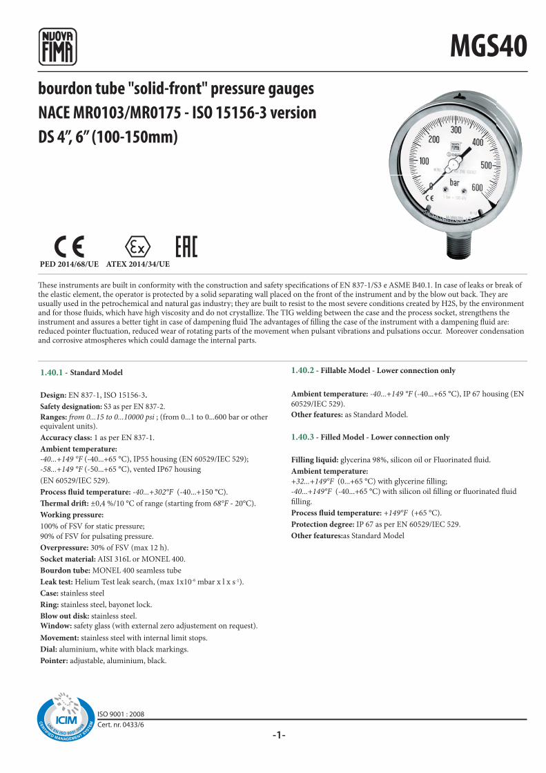
-1-
MGS40
PED 2014/68/UE ATEX 2014/34/UE
These instruments are built in conformity with the construction and safety specifications of EN 837-1/S3 e ASME B40.1. In case of leaks or break of the elastic element, the operator is protected by a solid separating wall placed on the front of the instrument and by the blow out back. They are usually used in the petrochemical and natural gas industry; they are built to resist to the most severe conditions created by H2S, by the environment and for those fluids, which have high viscosity and do not crystallize. The TIG welding between the case and the process socket, strengthens the instrument and assures a better tight in case of dampening fluid The advantages of filling the case of the instrument with a dampening fluid are: reduced pointer fluctuation, reduced wear of rotating parts of the movement when pulsant vibrations and pulsations occur. Moreover condensation and corrosive atmospheres which could damage the internal parts.
bourdon tube "solid-front" pressure gaugesNACE MR0103/MR0175 - ISO 15156-3 versionDS 4”, 6” (100-150mm)
1.40.1 - Standard Model
Design: EN 837-1, ISO 15156-3.
Safety designation: S3 as per EN 837-2.
Ranges: from 0...15 to 0...10000 psi ; (from 0...1 to 0...600 bar or other equivalent units).
Accuracy class: 1 as per EN 837-1.
Ambient temperature:
-40...+149 °F (-40...+65 °C), IP55 housing (EN 60529/IEC 529);
-58...+149 °F (-50...+65 °C), vented IP67 housing
(EN 60529/IEC 529).
Process fluid temperature: -40...+302°F (-40...+150 °C).
Thermal drift: ±0,4 %/10 °C of range (starting from 68°F - 20°C).
Working pressure:
100% of FSV for static pressure;
90% of FSV for pulsating pressure.
Overpressure: 30% of FSV (max 12 h).
Socket material: AISI 316L or MONEL 400.
Bourdon tube: MONEL 400 seamless tube
Leak test: Helium Test leak search, (max 1x10⁻⁶ mbar x l x s-1).
Case: stainless steel
Ring: stainless steel, bayonet lock.
Blow out disk: stainless steel.Window: safety glass (with external zero adjustement on request).
Movement: stainless steel with internal limit stops.
Dial: aluminium, white with black markings.
Pointer: adjustable, aluminium, black.
1.40.2 - Fillable Model - Lower connection only
Ambient temperature: -40...+149 °F (-40...+65 °C), IP 67 housing (EN
60529/IEC 529).
Other features: as Standard Model.
1.40.3 - Filled Model - Lower connection only
Filling liquid: glycerina 98%, silicon oil or Fluorinated fluid.
Ambient temperature:
+32...+149°F (0...+65 °C) with glycerine filling;
-40...+149°F (-40...+65 °C) with silicon oil filling or fluorinated fluid
filling.
Process fluid temperature: +149°F (+65 °C).
Protection degree: IP 67 as per EN 60529/IEC 529.
Other features:as Standard Model
ISO 9001 : 2008Cert. nr. 0433/6

MGS40
◆
◆
◆◆
◆
◆◆
◆◆
◆
◆ ◆ ◆◆ ◆
◆
◆ ◆
◆
◆
◆◆
◆ ◆
RC5
- 03/
14
F a b c d d1
e h p L
E
G
E
G
2D1 -
C40 -
E07 -
C -
E -
2G1 -
E30 -
F30 -
P01 -
P03 -
S10 -
ECV -
E67 -
T01 -
41M - G 1/2 A
41M - G 1/2 A
41M - G 1/2 A
41M - G 1/2 A
43M - 1/2-14 NPT
43M - 1/2-14 NPT
43M - 1/2-14 NPT
43M - 1/2-14 NPT
“HOW TO ORDER” SEQUENCE
Section / Model / Case / Mounting / Diameter / Special version /Range / Process connection / Options
1 40 1 A E -- 41M C...E 2 D G E07 43M 2G1...T01 3
bourdon tube "solid-front" pressure gauges,NACE MR0103/MR0175 - ISO15156-3 version, DS 4”, 6” (100-150mm)
OPTIONS
Model
AISI 316L st. st. case, ring and blow out disk
Suitable for filling with silicone/Fluorinated fluid
Fluorinated fluid filling
Compensating device, for DS 4” (100 mm) and lower mounting only
standard fillable filled
ATEX II 2GD c version
ATEX II 2G c version
NACE MR0103/MR0175 - ISO 15156-3 certificate
Socket material MONEL 400
Silicone filling
See the ATEX pressure gauges data-sheet for technical details
dimensions : inches (mm) (1) add 0.73 lbs (0,33 kg) for DS 4” (100) and 1.76 lbs (0,8 kg) for DS 6” (150), when filled
Back flange, for lower connection pressure gauges
Front flange, for back connection pressure gauges
Lower
Back
Mounting DS Weight (1)
(13)
0.51”
(15)
0.59”
(13)
0.51”
(13)
0.59”
(62,5)
2.46”
(64)
(62,5)
(64)
(29,5)
1.16”
(30)
(110,6)
4.35”
(161)
(110,6)
(161)
(101)
3.97”
(150,5)
(101)
(150,5)
(31)
(31)
(86)
3.38”
(117)
(95,5)
(96)
(20)
0.78”
(20)
0.78”
(20)
0.78”
(20)
0.78”
(0,65 kg)
1.43 lbs (1)
(1,2 kg)
2.64 lbs (1)
(0,70 kg)
1.54 lbs
(1,15 kg)
2.53 lbs
4.60”5.92”6.33”1.18”2.51”
3.75”1.22”3.97”4.35”2.46”
3.77”1.22”5.92”6.33”2.51”
A - LOWER CONNECTION D - BACK CONNECTION,
Standard model only
4” (100)
6” (150)
4” (100)
6” (150)
Tropicalization
(1) to be ordered with E67 option
(2) lower mounting and not adjustable pointer
(3) to be ordered with ECV option
Vented housing version, Ambient temperature -50...+65 °C (1) (2)
Protection degree IP67 (3)
IN O
RD
ER
TO
IM
PR
OV
E T
HE
IR P
RO
DU
CT
ION
, ME
SSR
S. N
UO
VA
FIM
A R
ESE
RV
E T
HE
RIG
HT
TO
TH
EM
SELV
ES
TO
MA
KE
AL
L T
HE
MO
DIF
ICA
TIO
NS
TH
AT
TH
EY
DE
EM
IN
DIS
PE
NSA
BL
E A
T A
NY
TIM
E. U
PD
AT
ED
DA
TA
-SH
EE
TS
AR
E A
VA
ILA
BL
E O
N S
ITE
: ww
w.n
uo
vafi
ma.
com
Copyright © Nuova Fima srl. All rights reserved. Any part of this publication should not be reproduced without a written Nuova Fima’s srl approval
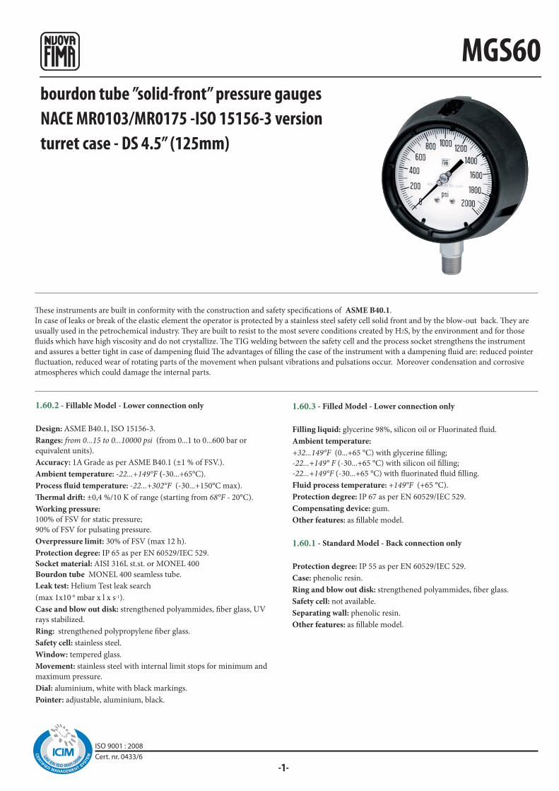
-1-
MGS60
ISO 9001 : 2008Cert. nr. 0433/6
bourdon tube ”solid-front” pressure gaugesNACE MR0103/MR0175 -ISO 15156-3 versionturret case - DS 4.5” (125mm)
1.60.2 - Fillable Model - Lower connection only
Design: ASME B40.1, ISO 15156-3.
Ranges: from 0...15 to 0...10000 psi (from 0...1 to 0...600 bar or
equivalent units).
Accuracy: 1A Grade as per ASME B40.1 (±1 % of FSV.).
Ambient temperature: -22...+149°F (-30...+65°C).
Process fluid temperature: -22...+302°F (-30...+150°C max).
Thermal drift: ±0,4 %/10 K of range (starting from 68°F - 20°C).
Working pressure:
100% of FSV for static pressure;
90% of FSV for pulsating pressure.
Overpressure limit: 30% of FSV (max 12 h).
Protection degree: IP 65 as per EN 60529/IEC 529.
Socket material: AISI 316L st.st. or MONEL 400
Bourdon tube MONEL 400 seamless tube.
Leak test: Helium Test leak search
(max 1x10⁻⁶ mbar x l x s-1).
Case and blow out disk: strengthened polyammides, fiber glass, UV
rays stabilized.
Ring: strengthened polypropylene fiber glass.
Safety cell: stainless steel.
Window: tempered glass.
Movement: stainless steel with internal limit stops for minimum and
maximum pressure.
Dial: aluminium, white with black markings.
Pointer: adjustable, aluminium, black.
1.60.3 - Filled Model - Lower connection only
Filling liquid: glycerine 98%, silicon oil or Fluorinated fluid.
Ambient temperature:
+32...149°F (0...+65 °C) with glycerine filling;
-22...+149° F (-30...+65 °C) with silicon oil filling;
-22...+149°F (-30...+65 °C) with fluorinated fluid filling.
Fluid process temperature: +149°F (+65 °C).
Protection degree: IP 67 as per EN 60529/IEC 529.
Compensating device: gum.
Other features: as fillable model.
1.60.1 - Standard Model - Back connection only
Protection degree: IP 55 as per EN 60529/IEC 529.
Case: phenolic resin.
Ring and blow out disk: strengthened polyammides, fiber glass.
Safety cell: not available.
Separating wall: phenolic resin.
Other features: as fillable model.
These instruments are built in conformity with the construction and safety specifications of ASME B40.1.
In case of leaks or break of the elastic element the operator is protected by a stainless steel safety cell solid front and by the blow-out back. They are
usually used in the petrochemical industry. They are built to resist to the most severe conditions created by H2S, by the environment and for those
fluids which have high viscosity and do not crystallize. The TIG welding between the safety cell and the process socket strengthens the instrument
and assures a better tight in case of dampening fluid The advantages of filling the case of the instrument with a dampening fluid are: reduced pointer
fluctuation, reduced wear of rotating parts of the movement when pulsant vibrations and pulsations occur. Moreover condensation and corrosive
atmospheres which could damage the internal parts.

MGS60
◆
◆
◆◆
◆◆◆ ◆
◆ ◆
◆
◆◆
◆◆
◆◆
◆◆
RC5 -
03/1
4
F a b c d e E f chh p La1d 1 h 1
43M1/2-14 NPT
43M1/2-14 NPT
E30 -
F11 -
F30 -
E07 -
P01 -
P03 -
S10 -
T01 -
T32 -
“HOW TO ORDER” SEQUENCE
Section / Model / Case / Mounting / Diameter / Special version /Range / Process connection / Options
1 60 1 A F --- 41M E30...T32 2 D E07 3
D - BACK CONNECTION,
FOR STANDARD MODEL ONLY
filled
bourdon tube "solid-front" pressure gauges NACE MR0103/MR0175 - ISO 15156-3 version, turret case DS 4.5” (125mm)
OPTIONS
Model
Silicone filling
Tropicalization
Safety glass window
Panel mounting kit
Fluorinated fluid filling
Suitable for filling with silicone/fluid filling
Blow out disk with compensating device
NACE MR0103/MR0175 - ISO 15156-3 certificate
Socket material MONEL 400
(1) add 1.10 lbs (0,5 kg) when filleddimensions : inches (mm)
standard fillable
Lower
Mounting
Back
Weight (1)
(13)
0.51”
(13)
0.51”
(86)
3.38”
(86)
(42)
1.65”(148)
5.82”
(148)
(126)
4.96”
(129)
(137)
5.39”(22)
0.86”
(17)
0.66”
(0,81 kg)
1.78 lbs
(0,81 kg)
1.78 lbs5.07”5.82”3.38”
(66,5)
2.61”
(66,5)
2.61”(31)
1.22”(6)
0.23”
(27)
1.06”
(27)
1.06”
(103,5)
4.07”
(106)
4.17”
(20)
0.78”
(20)
0.78”
(6,5)
0.25”
(137)
5.39”(103,5)
4.07”
A - LOWER CONNECTION
IN O
RD
ER
TO
IM
PR
OV
E T
HE
IR P
RO
DU
CT
ION
, ME
SSR
S. N
UO
VA
FIM
A R
ESE
RV
E T
HE
RIG
HT
TO
TH
EM
SELV
ES
TO
MA
KE
AL
L T
HE
MO
DIF
ICA
TIO
NS
TH
AT
TH
EY
DE
EM
IN
DIS
PE
NSA
BL
E A
T A
NY
TIM
E. U
PD
AT
ED
DA
TA
-SH
EE
TS
AR
E A
VA
ILA
BL
E O
N S
ITE
: ww
w.n
uo
vafi
ma.
com
Copyright © Nuova Fima S.r.l. All rights reserved. Any part of this publication should not be reproduced without a written Nuova Fima’s S.p.A. approval
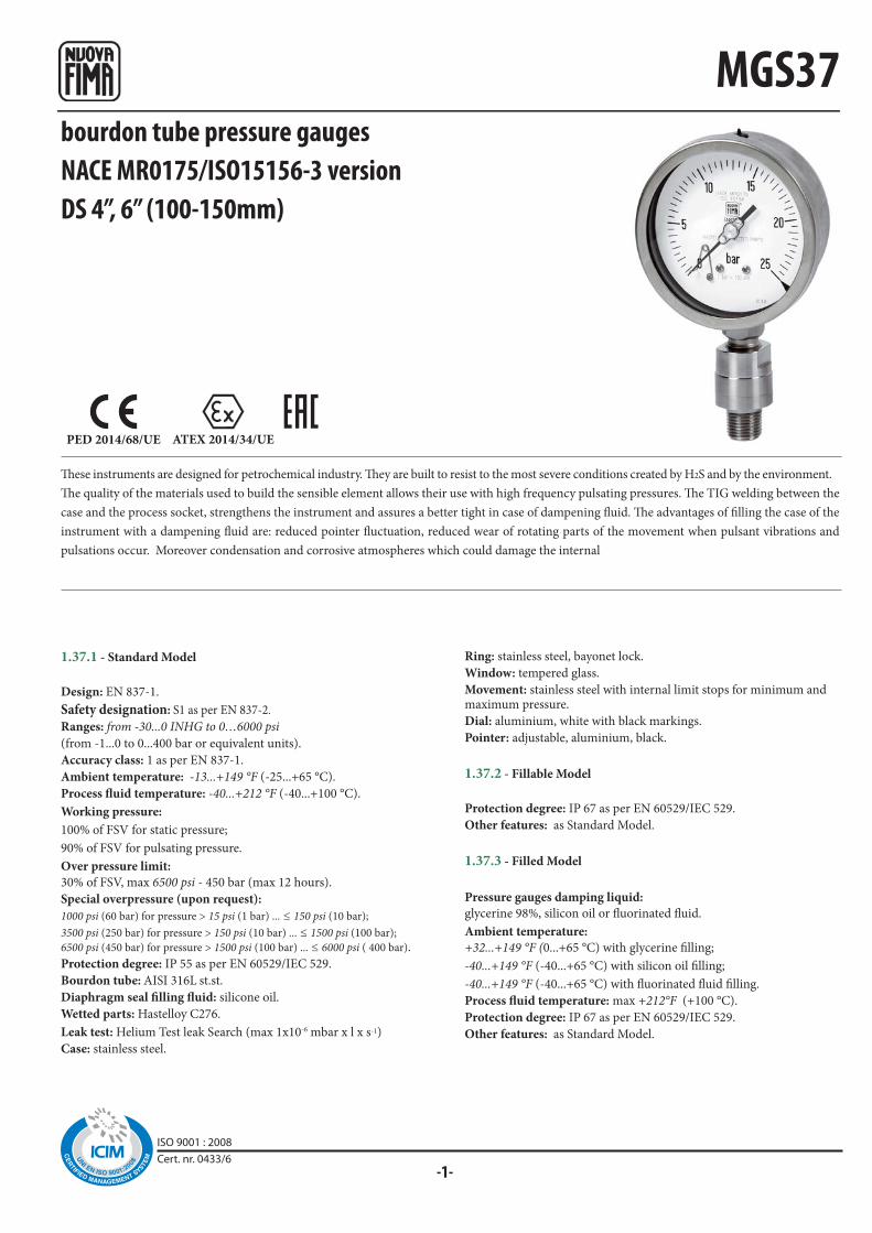
-1-
MGS37
PED 2014/68/UE ATEX 2014/34/UE
These instruments are designed for petrochemical industry. They are built to resist to the most severe conditions created by H2S and by the environment.
The quality of the materials used to build the sensible element allows their use with high frequency pulsating pressures. The TIG welding between the
case and the process socket, strengthens the instrument and assures a better tight in case of dampening fluid. The advantages of filling the case of the
instrument with a dampening fluid are: reduced pointer fluctuation, reduced wear of rotating parts of the movement when pulsant vibrations and
pulsations occur. Moreover condensation and corrosive atmospheres which could damage the internal
Ring: stainless steel, bayonet lock.
Window: tempered glass.
Movement: stainless steel with internal limit stops for minimum and maximum pressure.
Dial: aluminium, white with black markings.
Pointer: adjustable, aluminium, black.
1.37.2 - Fillable Model
Protection degree: IP 67 as per EN 60529/IEC 529.
Other features: as Standard Model.
1.37.3 - Filled Model
Pressure gauges damping liquid:
glycerine 98%, silicon oil or fluorinated fluid.
Ambient temperature:
+32...+149 °F (0...+65 °C) with glycerine filling;
-40...+149 °F (-40...+65 °C) with silicon oil filling;
-40...+149 °F (-40...+65 °C) with fluorinated fluid filling.
Process fluid temperature: max +212°F (+100 °C).
Protection degree: IP 67 as per EN 60529/IEC 529.
Other features: as Standard Model.
1.37.1 - Standard Model
Design: EN 837-1.
Safety designation: S1 as per EN 837-2.
Ranges: from -30...0 INHG to 0…6000 psi
(from -1...0 to 0...400 bar or equivalent units).
Accuracy class: 1 as per EN 837-1.
Ambient temperature: -13...+149 °F (-25...+65 °C).
Process fluid temperature: -40...+212 °F (-40...+100 °C).
Working pressure:
100% of FSV for static pressure;
90% of FSV for pulsating pressure.
Over pressure limit:
30% of FSV, max 6500 psi - 450 bar (max 12 hours).
Special overpressure (upon request):
1000 psi (60 bar) for pressure > 15 psi (1 bar) ... ≤ 150 psi (10 bar);
3500 psi (250 bar) for pressure > 150 psi (10 bar) ... ≤ 1500 psi (100 bar);
6500 psi (450 bar) for pressure > 1500 psi (100 bar) ... ≤ 6000 psi ( 400 bar).
Protection degree: IP 55 as per EN 60529/IEC 529.
Bourdon tube: AISI 316L st.st.
Diaphragm seal filling fluid: silicone oil.
Wetted parts: Hastelloy C276.
Leak test: Helium Test leak Search (max 1x10⁻⁶ mbar x l x s-1)
Case: stainless steel.
bourdon tube pressure gaugesNACE MR0175/ISO15156-3 versionDS 4”, 6” (100-150mm)
ISO 9001 : 2008Cert. nr. 0433/6
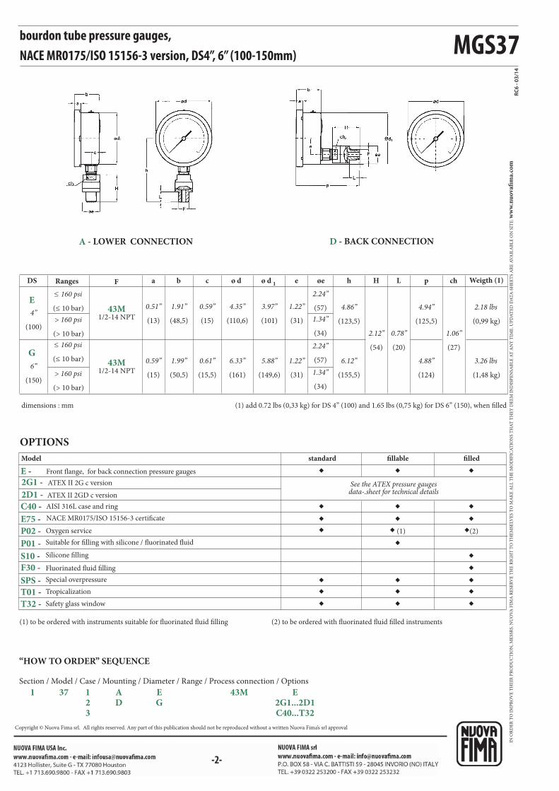
MGS37
◆◆
◆
◆◆
◆
◆◆
◆ ◆ ◆◆ ◆ ◆
◆ ◆ ◆
◆ ◆ ◆
◆ ◆ (1) ◆(2)
◆
øeø d 1 eF chLHhø dcba p
RC6
- 03/
14
E
G
43M1/2-14 NPT
43M1/2-14 NPT
E75 -
P02 -
P01 -
E -
C40 -
S10 -
F30 -
SPS -
T01 -
T32 -
2G1 -
2D1 -
Model
AISI 316L case and ring
Suitable for filling with silicone / fluorinated fluid
Silicone filling
Tropicalization
Safety glass window
OPTIONS
standard fillable filled
NACE MR0175/ISO 15156-3 certificate
Special overpressure
Front flange, for back connection pressure gauges
Oxygen service
(1) to be ordered with instruments suitable for fluorinated fluid filling (2) to be ordered with fluorinated fluid filled instruments
Fluorinated fluid filling
dimensions : mm (1) add 0.72 lbs (0,33 kg) for DS 4” (100) and 1.65 lbs (0,75 kg) for DS 6” (150), when filled
DS
(100)
(150)
(≤ 10 bar)
(≤ 10 bar)
(> 10 bar)
(> 10 bar)
Ranges
(27)
Weigth (1)
(0,99 kg)
(1,48 kg)
(20)(54)
(123,5)
(155,5)
(57)
(34)
(57)
(34)
(101)
(149,6)
(110,6)
(161)
(15)
(15,5)
(48,5)
(50,5)
(13)
(15)
(31)
(31)
(125,5)
(124)
bourdon tube pressure gauges, NACE MR0175/ISO 15156-3 version, DS4”, 6” (100-150mm)
4”
6”
≤ 160 psi
≤ 160 psi
> 160 psi
> 160 psi
1.06”
2.18 lbs
3.26 lbs
0.78”2.12”
4.86”
6.12”
2.24”
1.34”
2.24”
1.34”
3.97”
5.88”
4.35”
6.33”
0.59”
0.61”
1.91”
1.99”
0.51”
0.59”
1.22”
1.22”
4.94”
4.88”
A - LOWER CONNECTION D - BACK CONNECTION
“HOW TO ORDER” SEQUENCE
Section / Model / Case / Mounting / Diameter / Range / Process connection / Options
1 37 1 A E 43M E 2 D G 2G1...2D1 3 C40...T32
ATEX II 2GD c version
ATEX II 2G c version See the ATEX pressure gauges data-.sheet for technical details
IN O
RD
ER
TO
IM
PR
OV
E T
HE
IR P
RO
DU
CT
ION
, ME
SSR
S. N
UO
VA
FIM
A R
ESE
RV
E T
HE
RIG
HT
TO
TH
EM
SELV
ES
TO
MA
KE
AL
L T
HE
MO
DIF
ICA
TIO
NS
TH
AT
TH
EY
DE
EM
IN
DIS
PE
NSA
BL
E A
T A
NY
TIM
E. U
PD
AT
ED
DA
TA
-SH
EE
TS
AR
E A
VA
ILA
BL
E O
N S
ITE
: ww
w.n
uo
vafi
ma.
com
Copyright © Nuova Fima srl. All rights reserved. Any part of this publication should not be reproduced without a written Nuova Fima’s srl approval

-1-
MGS41
PED 2014/68/UE ATEX 2014/34/UE
These instruments are built in conformity with the construction and safety specifications of EN 837-1/S3 e ASME B40.1. In case of leaks or break of
the elastic element, the operator is protected by a solid separating wall placed on the front of the instrument and by the blow out back. They are usually
used in the petrochemical industry; they are built to resist to the most severe conditions created by H2S and by the environment. The TIG welding
between the case and the process socket, strengthens the instrument and assures a better tight in case of dampening fluid The advantages of filling the
case of the instrument with a dampening fluid are: reduced pointer fluctuation, reduced wear of rotating parts of the movement when pulsant vibrations
and pulsations occur. Moreover condensation and corrosive atmospheres which could damage the internal parts.
bourdon tube "solid-front" pressure gaugesNACE MR0175/ISO 15156-3 versionDS 4”, 6” (100-150mm)
1.41.1 - Standard Model
Design: EN 837-1.
Safety designation: S1 as per EN 837-2.
Ranges: from -30...0 INHG to 0…6000 psi (from -1...0 to 0...400 bar or equivalent units).
Accuracy class: 1 as per EN 837-1.
Ambient temperature: -13...+149 °F (-25...+65 °C).
Process fluid temperature: -40...+212 °F (-40...+100 °C).
Working pressure:
100% of FSV for static pressure;
90% of FSV for pulsating pressure.
Over pressure limit:
30% of FSV, max 6500 psi - 450 bar (max 12 hours).
Special overpressure (upon request):
1000 psi (60 bar) for pressure > 15 psi (1 bar) ... ≤ 150 psi (10 bar);
3500 psi (250 bar) for pressure > 150 psi (10 bar) ... ≤ 1500 psi (100 bar);
6500 psi (450 bar) for pressure > 1500 psi (100 bar) ... ≤ 6000 psi (400 bar).
Protection degree: IP 55 as per EN 60529/IEC 529.
Bourdon tube: AISI 316L st.st.
Diaphragm seal filling fluid: silicone oil.
Wetted parts: Hastelloy C276.
Leak test: Helium Test leak Search (max 1x10⁻⁶ mbar x l x s-1)
Case: stainless steel.
Ring: stainless steel, bayonet lock.
Blow out disk: stainless steel.
Window: safety glass.
Movement: stainless steel with internal limit stops for minimum and maximum pressure.
Dial: aluminium, white with black markings.
Pointer: adjustable, aluminium, black.
1.41.2 - Fillable Model
Protection degree: IP 67 as per EN 60529/IEC 529.
Other features: as Standard Model.
1.41.3 - Filled Model
Pressure gauges damping liquid:
glycerine 98%, silicon oil or fluorinated fluid.
Ambient temperature:
+32...+149 °F (0...+65 °C) with glycerine filling;
-40...+149 °F (-40...+65 °C) with silicon oil filling;
-40...+149 °F (-40...+65 °C) with fluorinated fluid filling.
Process fluid temperature: max +212°F (+100 °C).
Protection degree: IP 67 as per EN 60529/IEC 529.
Other features: as Standard Model.
ISO 9001 : 2008Cert. nr. 0433/6

MGS41
øe
◆
◆
◆
◆
◆
◆ ◆ ◆◆ ◆ ◆
◆ ◆ ◆
◆ ◆ (1) ◆ (2)
◆
F chLHhø dcba1
ø d
RC6
- 03/
14
E
G
43M1/2-14 NPT
43M1/2-14 NPT
E75 -
P02 -
P01 -
C40 -
S10 -
F30 -
SPS -
T01 -
2G1 - 2D1 -
bourdon tube “solid-front” pressure gauges, NACE MR0175/ISO 15156-3 version, DS4”, 6” (100-150mm)
Model
AISI 316L st. st. case and ring
Suitable for filling with silicone and fluorinated fluid
Silicone filling
Tropicalization
OPTIONS
standard fillable filled
NACE MR0175/ISO 15156-3 certificate
dimensions : inches (mm) (1) add 0.72 lbs (0,33 kg) for DS 4” (100) and 1.65 lbs (0,75 kg) for DS 6” (150), when filled
Special overpressure
> 160 psi (10 bar)
≤ 160 psi (10 bar)
≤ 160 psi (10 bar)
> 160 psi (10 bar)
RangesDS
4” (100)
6” (150)
(27)
1.06”
(20)
0.78”
Weight (1)
(1,11 kg)
2.44 lbs
(1,66 kg)
3.65 lbs
(54)
2.12”
(123,5)
4.86”
(155,5)
6.12”
(57)
2.24”
(34)
1.33”
(57)
2.24”
(34)
1.33”
(101)
3.97”
(149,6)
5.88”
(110,6)
4.35”
(161)
6.33”
(29,5)
1.16”
(30)
1.18”
(62,5)
2.46”
(64)
2.52”
(13)
0.51”
(15)
0.59”
Oxygen service
Fluorinated fluid filling
(1) to be ordered with instruments suitable for fluorinated fluid filling (2) to be ordered with fluorinated fluid filled instruments
A - LOWER CONNECTION
“HOW TO ORDER” SEQUENCE
Section / Model / Case / Mounting / Diameter / Range / Process connection / Options
1 41 1 A E 43M 2G1...2D1
2 G C40...T01 3
ATEX II 2GD c version
ATEX II 2G c version See the ATEX pressure gauges data-.sheet for technical details
IN O
RD
ER
TO
IM
PR
OV
E T
HE
IR P
RO
DU
CT
ION
, ME
SSR
S. N
UO
VA
FIM
A R
ESE
RV
E T
HE
RIG
HT
TO
TH
EM
SELV
ES
TO
MA
KE
AL
L T
HE
MO
DIF
ICA
TIO
NS
TH
AT
TH
EY
DE
EM
IN
DIS
PE
NSA
BL
E A
T A
NY
TIM
E. U
PD
AT
ED
DA
TA
-SH
EE
TS
AR
E A
VA
ILA
BL
E O
N S
ITE
: ww
w.n
uo
vafi
ma.
com
Copyright © Nuova Fima srl. All rights reserved. Any part of this publication should not be reproduced without a written Nuova Fima’s srl approval
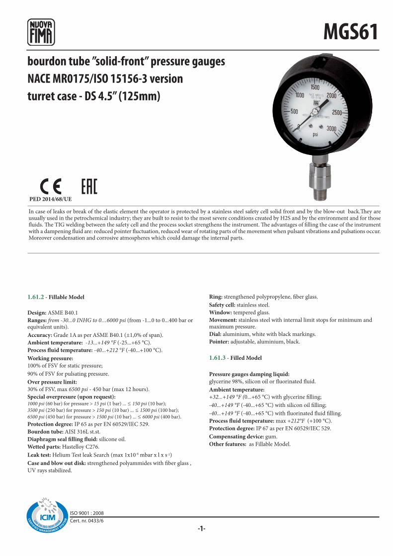
-1-
MGS61
PED 2014/68/UE
bourdon tube ”solid-front” pressure gaugesNACE MR0175/ISO 15156-3 versionturret case - DS 4.5” (125mm)
1.61.2 - Fillable Model
Design: ASME B40.1
Ranges: from -30...0 INHG to 0…6000 psi (from -1...0 to 0...400 bar or equivalent units).
Accuracy: Grade 1A as per ASME B40.1 (±1,0% of span).
Ambient temperature: -13...+149 °F (-25...+65 °C).
Process fluid temperature: -40...+212 °F (-40...+100 °C).
Working pressure:
100% of FSV for static pressure;
90% of FSV for pulsating pressure.
Over pressure limit:
30% of FSV, max 6500 psi - 450 bar (max 12 hours).
Special overpresure (upon request): 1000 psi (60 bar) for pressure > 15 psi (1 bar) ... ≤ 150 psi (10 bar);
3500 psi (250 bar) for pressure > 150 psi (10 bar) ... ≤ 1500 psi (100 bar);
6500 psi (450 bar) for pressure > 1500 psi (10 bar) ... ≤ 6000 psi (400 bar).
Protection degree: IP 65 as per EN 60529/IEC 529.
Bourdon tube: AISI 316L st.st.
Diaphragm seal filling fluid: silicone oil.
Wetted parts: Hastelloy C276.
Leak test: Helium Test leak Search (max 1x10⁻⁶ mbar x l x s-1)
Case and blow out disk: strengthened polyammides with fiber glass ,
UV rays stabilized.
Ring: strengthened polypropylene, fiber glass.
Safety cell: stainless steel.
Window: tempered glass.
Movement: stainless steel with internal limit stops for minimum and maximum pressure.
Dial: aluminium, white with black markings.
Pointer: adjustable, aluminium, black.
1.61.3 - Filled Model
Pressure gauges damping liquid:
glycerine 98%, silicon oil or fluorinated fluid.
Ambient temperature:
+32...+149 °F (0...+65 °C) with glycerine filling;
-40...+149 °F (-40...+65 °C) with silicon oil filling;
-40...+149 °F (-40...+65 °C) with fluorinated fluid filling.
Process fluid temperature: max +212°F (+100 °C).
Protection degree: IP 67 as per EN 60529/IEC 529.
Compensating device: gum.
Other features: as Fillable Model.
In case of leaks or break of the elastic element the operator is protected by a stainless steel safety cell solid front and by the blow-out back.They are usually used in the petrochemical industry; they are built to resist to the most severe conditions created by H2S and by the environment and for those fluids. The TIG welding between the safety cell and the process socket strengthens the instrument. The advantages of filling the case of the instrument with a dampening fluid are: reduced pointer fluctuation, reduced wear of rotating parts of the movement when pulsant vibrations and pulsations occur. Moreover condensation and corrosive atmospheres which could damage the internal parts.
ISO 9001 : 2008Cert. nr. 0433/6
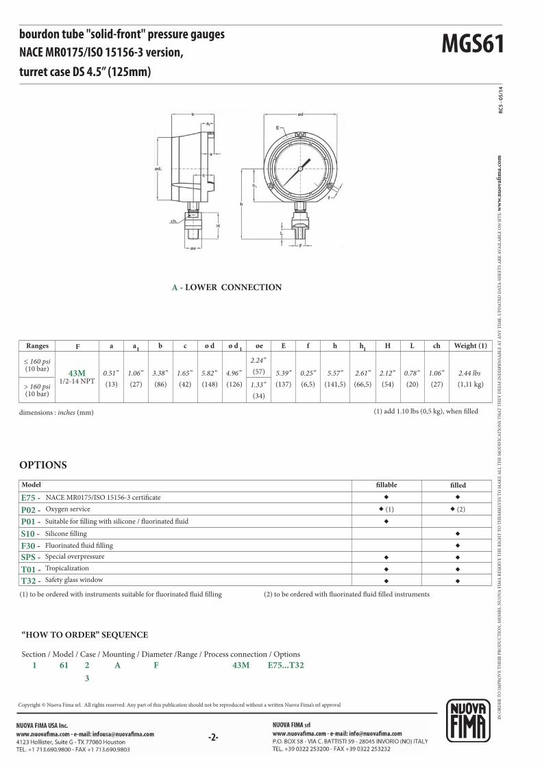
MGS61
øea1F a b c ø d hf h
1chLHE
◆
◆◆
◆
◆◆
◆ ◆
◆ ◆
◆ (1) ◆ (2)
◆
1ø d
RC5
- 05/
14
43M1/2-14 NPT
P02 -
P01 -
S10 -
E75 -
F30 -
SPS -
T01 -
T32 -
bourdon tube "solid-front" pressure gauges NACE MR0175/ISO 15156-3 version,turret case DS 4.5” (125mm)
dimensions : inches (mm) (1) add 1.10 lbs (0,5 kg), when filled
Model
Suitable for filling with silicone / fluorinated fluid
Silicone filling
Safety glass window
OPTIONS
fillable filled
NACE MR0175/ISO 15156-3 certificate
Special overpressure
> 160 psi(10 bar)
≤ 160 psi(10 bar)
Ranges
(13)
0.51”
(27)
1.06”
(86)
3.38”
(42)
1.65”
(148)
5.82”
(137)
5.39”
(141,5)
5.57”
(6,5)
0.25”
(66,5)
2.61”
Weight (1)
(1,11 kg)
2.44 lbs
(27)
1.06”
(20)
0.78”
(54)
2.12”(57)
2.24”
(34)
1.33”(126)
4.96”
Tropicalization
(1) to be ordered with instruments suitable for fluorinated fluid filling (2) to be ordered with fluorinated fluid filled instruments
Oxygen service
Fluorinated fluid filling
A - LOWER CONNECTION
“HOW TO ORDER” SEQUENCE
Section / Model / Case / Mounting / Diameter /Range / Process connection / Options
1 61 2 A F 43M E75...T32
3
IN O
RD
ER
TO
IM
PR
OV
E T
HE
IR P
RO
DU
CT
ION
, ME
SSR
S. N
UO
VA
FIM
A R
ESE
RV
E T
HE
RIG
HT
TO
TH
EM
SELV
ES
TO
MA
KE
AL
L T
HE
MO
DIF
ICA
TIO
NS
TH
AT
TH
EY
DE
EM
IN
DIS
PE
NSA
BL
E A
T A
NY
TIM
E. U
PD
AT
ED
DA
TA
-SH
EE
TS
AR
E A
VA
ILA
BL
E O
N S
ITE
: ww
w.n
uo
vafi
ma.
com
Copyright © Nuova Fima srl. All rights reserved. Any part of this publication should not be reproduced without a written Nuova Fima’s srl approval

◆◆◆◆◆◆
◆◆◆◆
◆◆
◆
R
◆◆◆◆◆◆
OM
PED 2014/68/EU
-1-
ISO 9001 : 2008Cert. nr. 0433/6
homogenizer gaugesDS 4” (100mm)
1.OM.2 - Fillable model
Design: 74-06 SSI; EN837-1.
Safety designation: S1 as per EN 837-2.
Ranges: from 0...2000 psi to 0...15000 psi; (from 0...160 bar to 0...1600
bar or equivalent units).
Accuracy: class 1,6 as per EN 837-1.
Ambient temperature: -13...+149 °F (-25...+65 °C).
Process temperature: -4...+248 °F (-20...+120 °C).
Max 302°F (150 °C) for 1 hour during sterilization (S.I.P)1.
Working pressure (referred to the full scale value): max 75%.
Over pressure limit: not available.
Seal fill: oil for food service (FDA).
Protection degree: IP 67 as per EN 60529/IEC 529.
Process connection: AISI 316L st.st. with finishing Ra ≤0,8 μm (welded
parts included).
Diaphragm: AISI 316L
Welding: AISI 316L TIG.
Flange and screw nut: AISI 316 st.st.
Case: stainless steel.
Ring: stainless steel, bayonet lock.
Elastic element: AISI 316L st.st. spiral form.
Window: tempered glass.
Movement: stainless steel.
Dial: aluminium, white with black markings.
Pointer: aluminium black anodized.
1.OM.3 - Filled model
Case filling liquid: glycerine 99,5% (USP, E.P. and F.U.) for food
service.
Ambient temperature: +59...+149 °F (+15...+65 °C).
Other features: as fillable model.
1) S.I.P. = Steamed In Place
These instruments are designed for homogenizer machines and are built according to standard n. 74-06 of 3-A organization (Sanitary Standards
Symbol Administrative Council). The absence of interstices and the mirror finishing of the components assure the best hygiene. The process
connection is a special diaphragm seal integrally built with the pressure gauge. To reduce the effects of severe operating conditions like vibrations
and pulsations, the instruments can be liquid filled. These types of sensors are intended for Manual (COP) Cleaning.
bar bar ext.
psi int.
RANGES psiRANGES
0...160
0...250
0...400
0...600
0...1000
0...1600
0...2000
0...3000
0...4000
0...5000
0...10000
0...15000
0...6000
74-06 Autorization NO. 1599
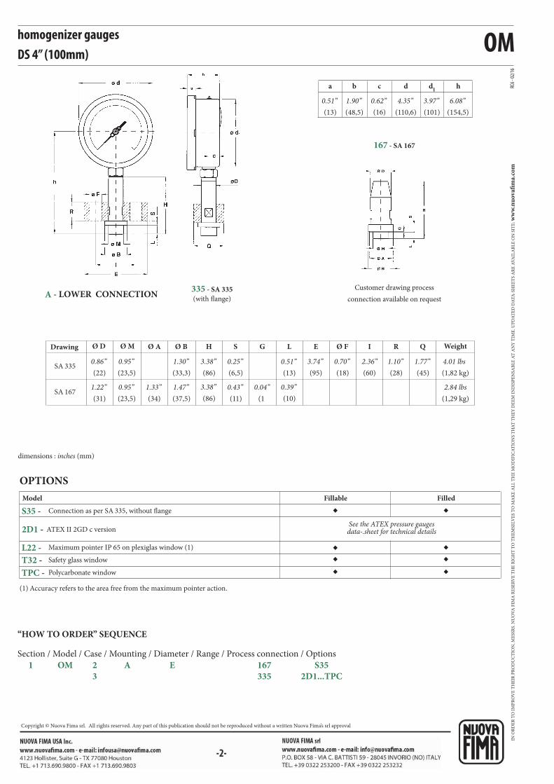
OM
◆
◆◆◆
◆
◆◆◆
SA 335
SA 167
Ø A GSØ BØ MØ D H L E QRØ F I
a b c d d1
h RC6 -
02/1
6S35 -
L22 -
T32 -
TPC -
2D1 -
homogenizer gaugesDS 4” (100mm)
OPTIONS
Model
(1) Accuracy refers to the area free from the maximum pointer action.
Safety glass window
Connection as per SA 335, without flange
Maximum pointer IP 65 on plexiglas window (1)
Polycarbonate window
Fillable Filled
Customer drawing process
connection available on request
335 - SA 335
(with flange)
Drawing
(34)
1.33”
Weight
(1,82 kg)
4.01 lbs
(1,29 kg)
2.84 lbs(1
0.04”
(6,5)
0.25”
(11)
0.43”
(33,3)
1.30”
(37,5)
1.47”
(23,5)
0.95”
(23,5)
0.95”
(22)
0.86”
(31)
1.22”
(86)
3.38”
(86)
3.38”(10)
0.39”
(13)
0.51”(95)
3.74”(45)
1.77”(28)
1.10”(18)
0.70”(60)
2.36”
dimensions : inches (mm)
(13)
0.51”(48,5)
1.90”(16)
0.62”(110,6)
4.35”(101)
3.97”(154,5)
6.08”
A - LOWER CONNECTION
167 - SA 167
“HOW TO ORDER” SEQUENCE
Section / Model / Case / Mounting / Diameter / Range / Process connection / Options
1 OM 2 A E 167 S35
3 335 2D1...TPC
ATEX II 2GD c versionSee the ATEX pressure gauges
data-.sheet for technical details
IN O
RD
ER
TO
IM
PR
OV
E T
HE
IR P
RO
DU
CT
ION
, ME
SSR
S. N
UO
VA
FIM
A R
ESE
RV
E T
HE
RIG
HT
TO
TH
EM
SELV
ES
TO
MA
KE
AL
L T
HE
MO
DIF
ICA
TIO
NS
TH
AT
TH
EY
DE
EM
IN
DIS
PE
NSA
BL
E A
T A
NY
TIM
E. U
PD
AT
ED
DA
TA
-SH
EE
TS
AR
E A
VA
ILA
BL
E O
N S
ITE
: ww
w.n
uo
vafi
ma.
com
NUOVA FIMA S.p.A. - www.nuovafima.comP.O. BOX 58 - VIA C. BATTISTI 59 - 28045 INVORIO (NO) ITALYTEL. +39 0322 253200 - FAX +39 0322 253232
Copyright © Nuova Fima srl. All rights reserved. Any part of this publication should not be reproduced without a written Nuova Fima’s srl approval
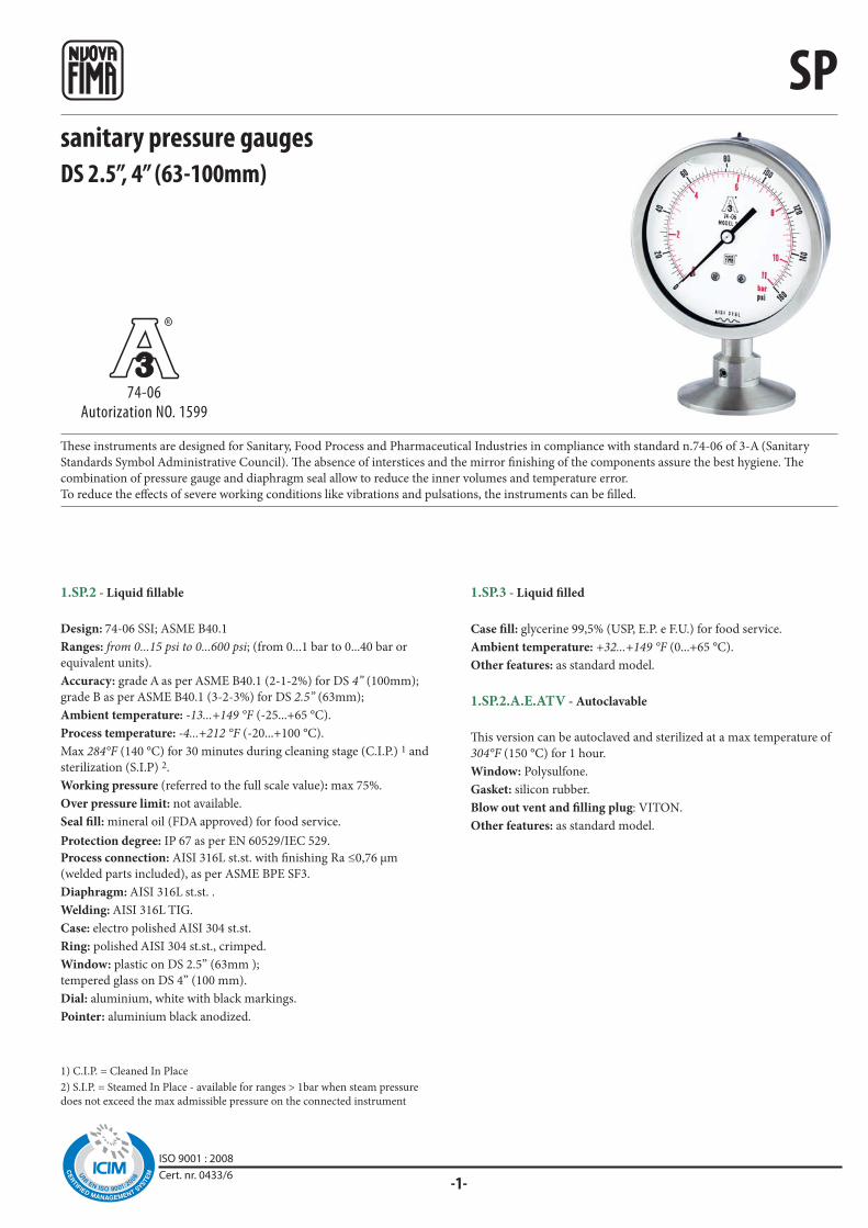
R
SP
-1-
ISO 9001 : 2008Cert. nr. 0433/6
sanitary pressure gaugesDS 2.5”, 4” (63-100mm)
These instruments are designed for Sanitary, Food Process and Pharmaceutical Industries in compliance with standard n.74-06 of 3-A (Sanitary
Standards Symbol Administrative Council). The absence of interstices and the mirror finishing of the components assure the best hygiene. The
combination of pressure gauge and diaphragm seal allow to reduce the inner volumes and temperature error.
To reduce the effects of severe working conditions like vibrations and pulsations, the instruments can be filled.
74-06Autorization NO. 1599
1.SP.2 - Liquid fillable
Design: 74-06 SSI; ASME B40.1
Ranges: from 0...15 psi to 0...600 psi; (from 0...1 bar to 0...40 bar or
equivalent units).
Accuracy: grade A as per ASME B40.1 (2-1-2%) for DS 4” (100mm);
grade B as per ASME B40.1 (3-2-3%) for DS 2.5” (63mm);
Ambient temperature: -13...+149 °F (-25...+65 °C).
Process temperature: -4...+212 °F (-20...+100 °C).
Max 284°F (140 °C) for 30 minutes during cleaning stage (C.I.P.) 1 and
sterilization (S.I.P) 2.
Working pressure (referred to the full scale value): max 75%.
Over pressure limit: not available.
Seal fill: mineral oil (FDA approved) for food service.
Protection degree: IP 67 as per EN 60529/IEC 529.
Process connection: AISI 316L st.st. with finishing Ra ≤0,76 μm
(welded parts included), as per ASME BPE SF3.
Diaphragm: AISI 316L st.st. .
Welding: AISI 316L TIG.
Case: electro polished AISI 304 st.st.
Ring: polished AISI 304 st.st., crimped.
Window: plastic on DS 2.5” (63mm );
tempered glass on DS 4” (100 mm).
Dial: aluminium, white with black markings.
Pointer: aluminium black anodized.
1.SP.3 - Liquid filled
Case fill: glycerine 99,5% (USP, E.P. e F.U.) for food service.
Ambient temperature: +32...+149 °F (0...+65 °C).
Other features: as standard model.
1.SP.2.A.E.ATV - Autoclavable
This version can be autoclaved and sterilized at a max temperature of
304°F (150 °C) for 1 hour.
Window: Polysulfone.
Gasket: silicon rubber.
Blow out vent and filling plug: VITON.
Other features: as standard model.
1) C.I.P. = Cleaned In Place
2) S.I.P. = Steamed In Place - available for ranges > 1bar when steam pressure
does not exceed the max admissible pressure on the connected instrument
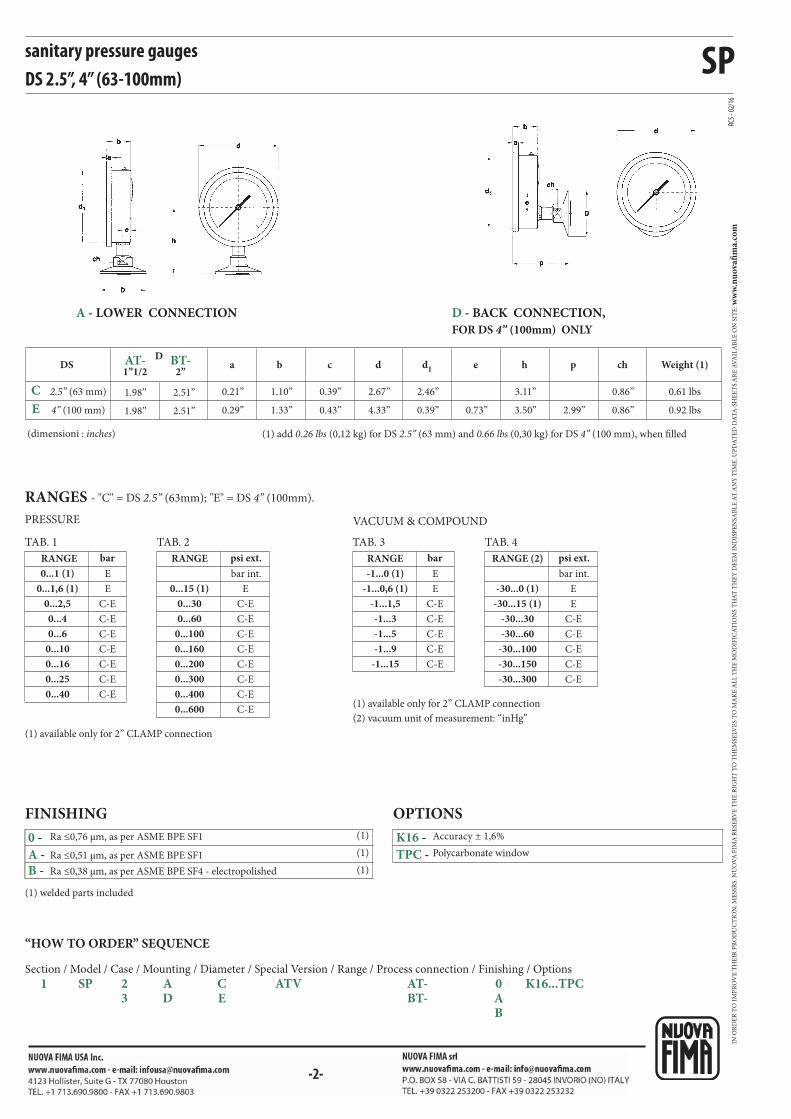
SP
C-E
C-E
C-E
C-E
C-E
C-E
C-E
E
E
C-E
C-E
C-E
C-E
C-E
E
E
C-E
C-E
C-E
C-E
C-E
C-E
C-E
E
C-E
E
C-E
C-E
C-E
C-E
E
C-E
a b c dD
d1 e h p ch
RC5 -
02/1
6
E
C
0 -
A - B -
K16 -
TPC -
AT-1”1/2
BT-2”
(1)
(1)
(1)
sanitary pressure gaugesDS 2.5”, 4” (63-100mm)
PRESSURE VACUUM & COMPOUND
RANGES - "C" = DS 2.5” (63mm); "E" = DS 4” (100mm).
TAB. 1
RANGE
TAB. 3
RANGE
TAB. 2
RANGE
TAB. 4
RANGE (2)
(1) available only for 2” CLAMP connection
(1) available only for 2” CLAMP connection
(2) vacuum unit of measurement: “inHg”
barpsi ext.
bar int.
psi ext.
bar int.
bar
0.21”
0.29”
1.10”
1.33”
0.39”
0.43”
2.67”
4.33”
2.46”
0.39”
1.98”
1.98”
2.51”
2.51” 0.73”
3.11”
3.50” 2.99”
0.86”
0.86”
DS
2.5” (63 mm)
4” (100 mm)
Weight (1)
0.61 lbs
0.92 lbs
(dimensioni : inches) (1) add 0.26 lbs (0,12 kg) for DS 2.5” (63 mm) and 0.66 lbs (0,30 kg) for DS 4” (100 mm), when filled
FINISHING
-30...0 (1)
-30...15 (1)
-30...30
-30...60
-30...100
-30...150
-30...300
-1...0 (1)
-1...0,6 (1)
-1...1,5
-1...3
-1...5
-1...9
-1...15
0...600
0...15 (1)
0...30
0...60
0...100
0...160
0...200
0...300
0...4000...40
0...1 (1)
0...1,6 (1)
0...2,5
0...4
0...6
0...10
0...16
0...25
A - LOWER CONNECTION D - BACK CONNECTION,
FOR DS 4” (100mm) ONLY
“HOW TO ORDER” SEQUENCE
Section / Model / Case / Mounting / Diameter / Special Version / Range / Process connection / Finishing / Options
1 SP 2 A C ATV AT- 0 K16...TPC 3 D E BT- A B
Ra ≤0,51 μm, as per ASME BPE SF1
Ra ≤0,76 μm, as per ASME BPE SF1
Ra ≤0,38 μm, as per ASME BPE SF4 - electropolished
OPTIONS
Accuracy ± 1,6%
Polycarbonate window
(1) welded parts included
IN O
RD
ER
TO
IM
PR
OV
E T
HE
IR P
RO
DU
CT
ION
, ME
SSR
S. N
UO
VA
FIM
A R
ESE
RV
E T
HE
RIG
HT
TO
TH
EM
SELV
ES
TO
MA
KE
AL
L T
HE
MO
DIF
ICA
TIO
NS
TH
AT
TH
EY
DE
EM
IN
DIS
PE
NSA
BL
E A
T A
NY
TIM
E. U
PD
AT
ED
DA
TA
-SH
EE
TS
AR
E A
VA
ILA
BL
E O
N S
ITE
: ww
w.n
uo
vafi
ma.
com
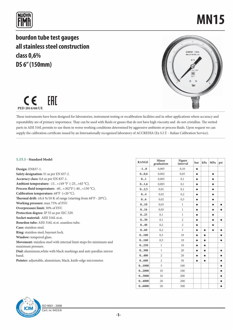
-1-
0,005
0,002
0,005
0,005
0,01
0,02
0,02
0,05
0,05
0,1
0,1
0,2
0,2
0,5
0,5
1
1
2
2
5
10
10
20
20
0,10
0,05
0,1
0,1
0,1
0,2
0,5
1
1
1
2
2
5
10
10
10
20
20
50
100
100
200
200
500
◆◆◆◆◆◆◆◆◆◆◆◆◆◆◆◆◆◆◆
◆◆◆◆◆◆◆
◆◆◆◆◆◆◆◆◆◆◆◆
◆◆
◆
◆◆◆
◆◆◆◆◆◆◆◆
MN15
ISO 9001 : 2008Cert. nr. 0433/6
PED 2014/68/UE
These instruments have been designed for laboratories, instrument testing or recalibration facilities and in other applications where accuracy and
repeatability are of primary importance. Thay can be used with fluids or gasses that do not have high viscosity and do not cristallize. The wetted
parts in AISI 316L permits to use them in worse working conditions determined by aggressive ambients or process fluids. Upon request we can
supply the calibration certificate issued by an Internationally recognized laboratory of ACCREDIA (Ex S.I.T. - Italian Calibration Service).
bourdon tube test gaugesall stainless steel constructionclass 0,6%DS 6” (150mm)
1.15.1 - Standard Model
Design: EN837-1.
Safety designation: S1 as per EN 837-2.
Accuracy class: 0,6 as per EN 837-1.
Ambient temperature: -13...+149 °F (-25...+65 °C).
Process fluid temperature: -40...+302°F (-40...+150 °C).
Calibration temperature: 68°F (+20 °C).
Thermal drift: ±0,4 %/10 K of range (starting from 68°F - 20°C).
Working pressure: max 75% of FSV.
Overpressure limit: 30% of FSV.
Protection degree: IP 55 as per IEC 529.
Socket material: AISI 316L st.st.
Bourdon tube: AISI 316L st.st. seamless tube.
Case: stainless steel.
Ring: stainless steel, bayonet lock.
Window: tempered glass.
Movement: stainless steel with internal limit stops fro minimum and
maximum pressure.
Dial: aluminium,white with black markings and anti-parallax mirror
band.
Pointer: adjustable, aluminium, black, knife-edge micrometer.
Figureinterval bar kPa MPa psi
-1...0
0...0,6
0...1
0...1,6
0...2,5
0...4
0...6
0...10
0...16
0...25
0...30
0...40
0...60
0...100
0...160
0...250
0...300
0...400
0...600
0...1000
0...2000
0...3000
0...4000
0...6000
RANGEMinor
graduation

MN15
ød1F a b c ød e p Lchh
RC4 -
05/1
4
41M - G 1/2 A
41M - G 1/2 A
43M - 1/2-14 NPT
43M - 1/2-14 NPT
B -
C -
E -
CE1 -
CE3 -
T32 -
bourdon tube test gaugesall stainless steel construction, class 0,6%, DS 6” (150mm)
dimensions : inches (mm)
OPTIONS
ACCREDIA certificate (pressure gauges)
ACCREDIA certificate (vacuum gauges)
Safety glass window
“U”-clamp, for back connection pressure gauges
Back flange, for lower connection pressure gauges
Front flange, for back connection pressure gauges
Lower
Mounting
Back
Weight
(15)
0.59”
(15)
0.59”
(50,5)
1.91”
(50,5)
(15,5)
1.98”(161)
6.33”
(161)
(149,6)
5.88”
(149,6)
(20)
0.78”
(20)
0.78”
(0,94 kg)
2.07 lbs
(0,94 kg)
2.07 lbs5.88”6.33”1.91”(85,5)
3.36”
(22)
0.86”
(22)
0.86”(31)
1.22”
(117)
4.60”
A - LOWER CONNECTION D - BACK CONNECTION
“HOW TO ORDER” SEQUENCE
Section / Model / Case / Mounting / Diameter / Range / Process connection / Options
1 15 1 A G 41M B...E
D 43M CE1...T32
PRESSURE GAUGE HOLDER CASE
Instruments with radial connection can be supplied of pressure gauge holder case, codE 5VAL.
IN O
RD
ER
TO
IM
PR
OV
E T
HE
IR P
RO
DU
CT
ION
, ME
SSR
S. N
UO
VA
FIM
A R
ESE
RV
E T
HE
RIG
HT
TO
TH
EM
SELV
ES
TO
MA
KE
AL
L T
HE
MO
DIF
ICA
TIO
NS
TH
AT
TH
EY
DE
EM
IN
DIS
PE
NSA
BL
E A
T A
NY
TIM
E. U
PD
AT
ED
DA
TA
-SH
EE
TS
AR
E A
VA
ILA
BL
E O
N S
ITE
: ww
w.n
uo
vafi
ma.
com
NUOVA FIMA S.p.A. - www.nuovafima.comP.O. BOX 58 - VIA C. BATTISTI 59 - 28045 INVORIO (NO) ITALYTEL. +39 0322 253200 - FAX +39 0322 253232
Copyright © Nuova Fima srl. All rights reserved. Any part of this publication should not be reproduced without a written Nuova Fima’s srl approval

-1-
0,005
0,002
0,005
0,005
0,01
0,02
0,02
0,05
0,05
0,1
0,1
0,2
0,2
0,5
0,5
1
1
2
2
5
10
10
20
20
0,10
0,05
0,1
0,1
0,1
0,2
0,5
1
1
1
2
2
5
10
10
10
20
20
50
100
100
200
200
500
◆◆◆◆◆◆◆◆◆◆◆◆◆◆◆◆◆◆◆
◆◆◆◆◆◆◆
◆◆◆◆◆◆◆◆◆◆◆◆
◆◆
◆
◆◆◆
◆◆◆◆◆◆◆◆
MN16
PED 2014/68/UE
These instruments have been designed for laboratories, instrument testing or recalibration facilities and in other applications where accuracy and
repeatability are of primary importance. These intruments have a solid separating wall in stainless steel, placed between the dial and the elastic
element and an integral blow out back that is released from the case whenever a pressure is created inside the case, due to leaks or accidental ruptures
of the elastic element. Thay can be used with fluids or gasses that do not have high viscosity and do not cristallize. The wetted parts in AISI 316L
permits to use them in worse working conditions determined by aggressive ambients or process fluids. Upon request we can supply the calibration
certificate issued by an Internationally recognized laboratory of ACCREDIA (Ex S.I.T. - Italian Calibration Service).
bourdon tube test gaugesall stainless steel construction, “solid-front” class 0,6%DS 6” (150mm)
1.16.1 - Standard Model
Design: EN837-1.
Safety designation: S3 as per EN 837-2.
Accuracy class: 0,6 as per EN 837-1.
Ambient temperature: -13...+149 °F (-25...+65 °C).
Process fluid temperature: -40...+302°F (-40...+150 °C).
Calibration temperature: 68°F (+20 °C).
Thermal drift: ±0,4 %/10 K of range (starting from 68°F - 20°C).
Working pressure: max 75% of FSV.
Overpressure limit: 30% of FSV.
Protection degree: IP 55 as per IEC 529.
Socket material: AISI 316L st.st.
Bourdon tube: AISI 316L st.st. seamless tube.
Case: stainless steel.
Ring: stainless steel, bayonet lock.
Blow out disk: stainless steel
Window: safety glass.
Movement: stainless steel with internal limit stops of minimum and
maximum pressure.
Dial: aluminium, white with black markings and anti-parallax mirror
band
Pointer: adjustable, aluminium, black, knife-edge micrometer
bar kPa MPa psiRANGEFigure
intervalMinor
graduation
-1...0
0...0,6
0...1
0...1,6
0...2,5
0...4
0...6
0...10
0...16
0...25
0...30
0...40
0...60
0...100
0...160
0...250
0...300
0...400
0...600
0...1000
0...2000
0...3000
0...4000
0...6000
ISO 9001 : 2008Cert. nr. 0433/6
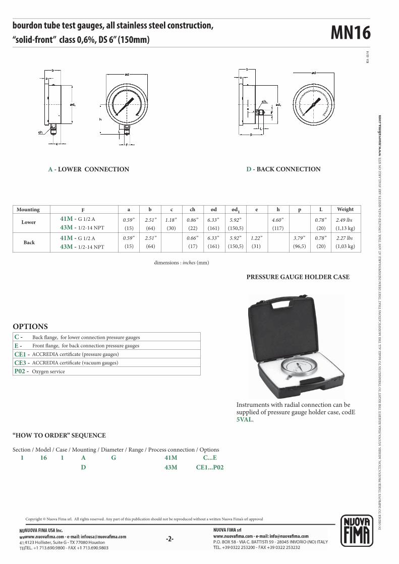
MN16
a b c ød e h p Lch ød1F
RC4 -
05/1
4
41M - G 1/2 A
41M - G 1/2 A
43M - 1/2-14 NPT
43M - 1/2-14 NPT
C -
E -
CE1 -
CE3 -
P02 -
-2-
bourdon tube test gauges, all stainless steel construction, “solid-front” class 0,6%, DS 6” (150mm)
OPTIONS
ACCREDIA certificate (pressure gauges)
Oxygen service
ACCREDIA certificate (vacuum gauges)
dimensions : inches (mm)
Back flange, for lower connection pressure gauges
Front flange, for back connection pressure gauges
Lower
Mounting
Back
Weight
(15)
0.59”
(15)
(64)
2.51”
(64)
(30)
1.18”(161)
6.33”
(161)
(150,5)
5.92”
(150,5)
(117)
4.60”(20)
0.78”
(20)
0.78”
(1,13 kg)
2.49 lbs
(1,03 kg)
2.27 lbs5.92”
(22)
0.86”
(17) (31)
1.22”(96,5)
3.79”0.59” 6.33”2.51” 0.66”
A - LOWER CONNECTION D - BACK CONNECTION
“HOW TO ORDER” SEQUENCE
Section / Model / Case / Mounting / Diameter / Range / Process connection / Options
1 16 1 A G 41M C...E
D 43M CE1...P02 4
PRESSURE GAUGE HOLDER CASE
Instruments with radial connection can be supplied of pressure gauge holder case, codE 5VAL.
IN O
RD
ER
TO
IM
PR
OV
E T
HE
IR P
RO
DU
CT
ION
, ME
SSR
S. N
UO
VA
FIM
A R
ESE
RV
E T
HE
RIG
HT
TO
TH
EM
SELV
ES
TO
MA
KE
AL
L T
HE
MO
DIF
ICA
TIO
NS
TH
AT
TH
EY
DE
EM
IN
DIS
PE
NSA
BL
E A
T A
NY
TIM
E. U
PD
AT
ED
DA
TA
-SH
EE
TS
AR
E A
VA
ILA
BL
E O
N S
ITE
: ww
w.n
uo
vafi
ma.
com
NUOVA FIMA S.p.A. - www.nuovafima.comP.O. BOX 58 - VIA C. BATTISTI 59 - 28045 INVORIO (NO) ITALYTEL. +39 0322 253200 - FAX +39 0322 253232
Copyright © Nuova Fima srl. All rights reserved. Any part of this publication should not be reproduced without a written Nuova Fima’s srl approval
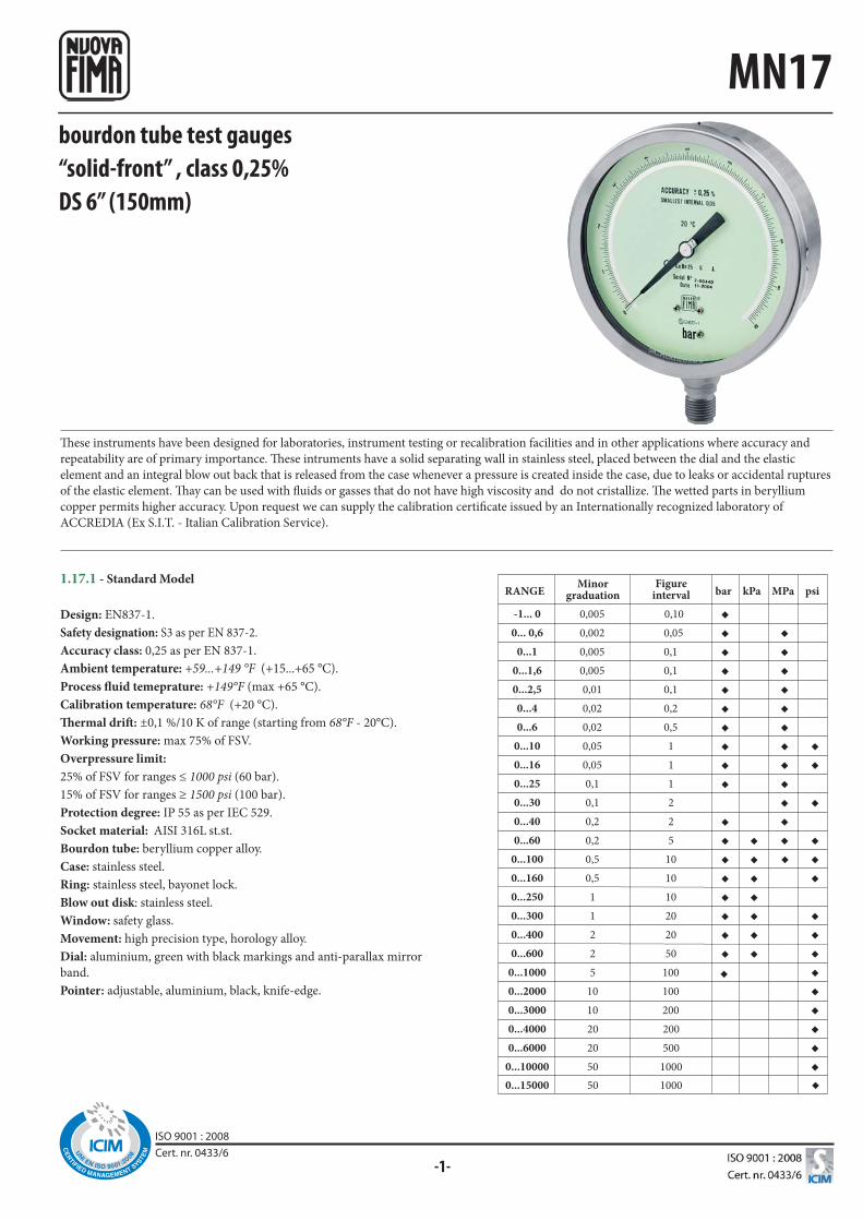
-1-
◆
0,005
0,002
0,005
0,005
0,01
0,02
0,02
0,05
0,05
0,1
0,1
0,2
0,2
0,5
0,5
1
1
2
2
5
10
10
20
20
50
0,10
0,05
0,1
0,1
0,1
0,2
0,5
1
1
1
2
2
5
10
10
10
20
20
50
100
100
200
200
500
1000
◆◆◆◆◆◆◆◆◆◆
◆◆◆◆◆◆◆◆
◆◆◆◆◆◆◆
◆◆◆◆◆◆◆◆◆◆◆◆
◆◆
◆
◆◆◆
◆◆◆◆◆◆◆◆◆
◆
50 1000
◆
MN17
These instruments have been designed for laboratories, instrument testing or recalibration facilities and in other applications where accuracy and
repeatability are of primary importance. These intruments have a solid separating wall in stainless steel, placed between the dial and the elastic
element and an integral blow out back that is released from the case whenever a pressure is created inside the case, due to leaks or accidental ruptures
of the elastic element. Thay can be used with fluids or gasses that do not have high viscosity and do not cristallize. The wetted parts in beryllium
copper permits higher accuracy. Upon request we can supply the calibration certificate issued by an Internationally recognized laboratory of
ACCREDIA (Ex S.I.T. - Italian Calibration Service).
bourdon tube test gauges“solid-front” , class 0,25%DS 6” (150mm)
1.17.1 - Standard Model
Design: EN837-1.
Safety designation: S3 as per EN 837-2.
Accuracy class: 0,25 as per EN 837-1.
Ambient temperature: +59...+149 °F (+15...+65 °C).
Process fluid temeprature: +149°F (max +65 °C).
Calibration temperature: 68°F (+20 °C).
Thermal drift: ±0,1 %/10 K of range (starting from 68°F - 20°C).
Working pressure: max 75% of FSV.
Overpressure limit:
25% of FSV for ranges ≤ 1000 psi (60 bar).
15% of FSV for ranges ≥ 1500 psi (100 bar).
Protection degree: IP 55 as per IEC 529.
Socket material: AISI 316L st.st.
Bourdon tube: beryllium copper alloy.
Case: stainless steel.
Ring: stainless steel, bayonet lock.
Blow out disk: stainless steel.
Window: safety glass.
Movement: high precision type, horology alloy.
Dial: aluminium, green with black markings and anti-parallax mirror
band.
Pointer: adjustable, aluminium, black, knife-edge.
bar kPa MPa psiRANGEFigure
intervalMinor
graduation
-1... 0
0... 0,6
0...1
0...1,6
0...2,5
0...4
0...6
0...10
0...16
0...25
0...30
0...40
0...60
0...100
0...160
0...250
0...300
0...400
0...600
0...1000
0...2000
0...3000
0...4000
0...6000
0...10000
0...15000
ISO 9001 : 2008Cert. nr. 0433/6
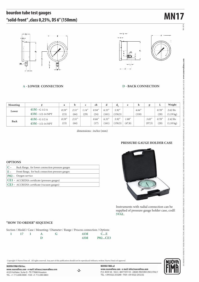
MN17
RC4 -
05/1
4
F a b c d d1
e h p Lch
C -
E -
P02 -
CE1 -
CE3 -
41M - G 1/2 A
41M - G 1/2 A
43M - 1/2-14 NPT
43M - 1/2-14 NPT
bourdon tube test gauges “solid-front” ,class 0,25%, DS 6” (150mm)
dimensions : inches (mm)
OPTIONS
ACCREDIA certificate (pressure gauges)
ACCREDIA certificate (vacuum gauges)
Oxygen service
Back flange, for lower connection pressure gauges
Front flange, for back connection pressure gauges
Lower
Mounting
Back
Weight
(15)
0.59”
(15)
(64)
2.51”
(64)
(29)
1.14”(161)
6.33”
(161)
(150,5)
5.92”
(150,5)
(118)
4.64”(20)
0.78”
(20)
0.78”
(1,19 kg)
2.62 lbs
(1,10 kg)
2.42 lbs5.92”
(24)
0.94”
(17) (47,8)
1.88”(97,5)
3.83”0.59” 6.33”2.51” 0.66”
A - LOWER CONNECTION D - BACK CONNECTION
“HOW TO ORDER” SEQUENCE
Section / Model / Case / Mounting / Diameter / Range / Process connection / Options
1 17 1 A G 41M C...E
D 43M P02...CE3
PRESSURE GAUGE HOLDER CASE
Instruments with radial connection can be supplied of pressure gauge holder case, codE 5VAL.
IN O
RD
ER
TO
IM
PR
OV
E T
HE
IR P
RO
DU
CT
ION
, ME
SSR
S. N
UO
VA
FIM
A R
ESE
RV
E T
HE
RIG
HT
TO
TH
EM
SELV
ES
TO
MA
KE
AL
L T
HE
MO
DIF
ICA
TIO
NS
TH
AT
TH
EY
DE
EM
IN
DIS
PE
NSA
BL
E A
T A
NY
TIM
E. U
PD
AT
ED
DA
TA
-SH
EE
TS
AR
E A
VA
ILA
BL
E O
N S
ITE
: ww
w.n
uo
vafi
ma.
com
NUOVA FIMA S.p.A. - www.nuovafima.comP.O. BOX 58 - VIA C. BATTISTI 59 - 28045 INVORIO (NO) ITALYTEL. +39 0322 253200 - FAX +39 0322 253232
Copyright © Nuova Fima srl. All rights reserved. Any part of this publication should not be reproduced without a written Nuova Fima’s srl approval

-1-
0,005
0,005
0,01
0,02
0,02
0,05
0,05
0,1
0,1
0,2
0,2
0,5
0,5
0,1
0,1
0,1
0,2
0,5
1
1
2
2
5
10
10
◆◆◆◆◆◆◆◆◆◆◆◆◆
◆◆
◆◆◆◆◆◆◆
◆
◆◆◆
◆◆◆1
MN25
These instruments have been designed for laboratories, instrument testing or recalibration facilities and to be used in other applications where accuracy
and repeatability are of primary importance. These intruments have a solid separating wall in stainless steel, placed between the dial and the elastic
element and an integral blow out back that is released from the case whenever a pressure is created inside the case, due to leaks or accidental ruptures
of the elastic element. The process fluids should be gases or liquids, they must not have high viscosity and must not cristalize. The wetted parts in AISI
316L allow to use them in the worst working conditions determined by aggressive medium and environment. Upon request we can supply the calibration
certificate issued by an Internationally recognized laboratory of ACCREDIA (Ex S.I.T. - Italian Calibration Service).
bourdon tube test gaugesall stainless steel construction, "solid-front" class 0,25%DS 6” (150mm)
1.25.1 - Standard Model
Design: EN 837-1.
Safety designation: S3 as per EN 837-2.
Accuracy class: 0,25 as per EN 837-1.
Ambient temperature: -4...+149 °F (-20...+65 °C).
Process fluid temeprature: +149°F (max +65 °C.)
Calibration temperature: 68°F (+20 °C).
Thermal drift: ±0,4 %/10 K of range (starting from 68°F - 20°C).
Working pressure: max 75% of FSV
Overpressure limit:
25% of FSV for ranges up to 1450 psi (100 bar);
15% of FSV for ranges over 1450 psi (100 bar).
Protection degree: IP 55 as per IEC 529.
Socket material: AISI 316L st.st.
Bourdon tube: AISI 316L st.st. seamless tube.
Case: stainless steel.
Ring: stainless steel, bayonet lock.
Blow out disk: stainless steel.
Window: safety glass.
Movement: high precision, horology alloy.
Dial: aluminium, white with black markings and anti-parallax mirror
band.
Pointer: adjustable, aluminium, black, knife-edge micrometer.
bar kPa MPa psiRANGEFigure interval
Minor graduation
0...1
0...1,6
0...2,5
0...4
0...6
0...10
0...16
0...25
0...30
0...40
0...60
0...100
0...160
ISO 9001 : 2008Cert. nr. 0433/6
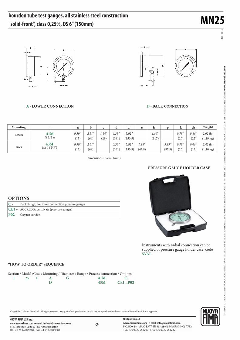
MN25
RC
5 -
08
/14
F a b c d d1
e h p L ch
41MG 1/2 A
43M1/2-14 NPT
CE1 -
P02 -
C -
bourdon tube test gauges, all stainless steel construction "solid-front", class 0,25%, DS 6” (150mm)
dimensions : inches (mm)
OPTIONS
ACCREDIA certificate (pressure gauges)
Oxygen service
Back flange, for lower connection pressure gauges
Lower
Mounting
Back
Weight
(15)
0.59”
(15)
(64)
2.51”
(64)
(29)
1.14”(161)
6.33”
(161)
(150,5)
5.92”
(150,5)
(117)
4.60”(20)
0.78”
(20)
0.78”
(1,19 kg)
2.62 lbs
(1,10 kg)
2.42 lbs5.92”
(22)
0.86”
(17)(47,8)
1.88”(97,5)
3.83”0.59” 6.33”2.51” 0.66”
D - BACK CONNECTIONA - LOWER CONNECTION
“HOW TO ORDER” SEQUENCE
Section / Model /Case / Mounting / Diameter / Range / Process connection / Options
1 25 1 A G 41M C D 43M CE1...P02
PRESSURE GAUGE HOLDER CASE
Instruments with radial connection can be supplied of pressure gauge holder case, code 5VAL.
IN O
RD
ER
TO
IM
PR
OV
E T
HE
IR P
RO
DU
CT
ION
, ME
SSR
S. N
UO
VA
FIM
A R
ESE
RV
E T
HE
RIG
HT
TO
TH
EM
SELV
ES
TO
MA
KE
AL
L T
HE
MO
DIF
ICA
TIO
NS
TH
AT
TH
EY
DE
EM
IN
DIS
PE
NSA
BL
E A
T A
NY
TIM
E. U
PD
AT
ED
DA
TA
-SH
EE
TS
AR
E A
VA
ILA
BL
E O
N S
ITE
: ww
w.n
uo
vafi
ma.
com
Copyright © Nuova Fima S.r.l. All rights reserved. Any part of this publication should not be reproduced without a written Nuova Fima’s S.p.A. approval
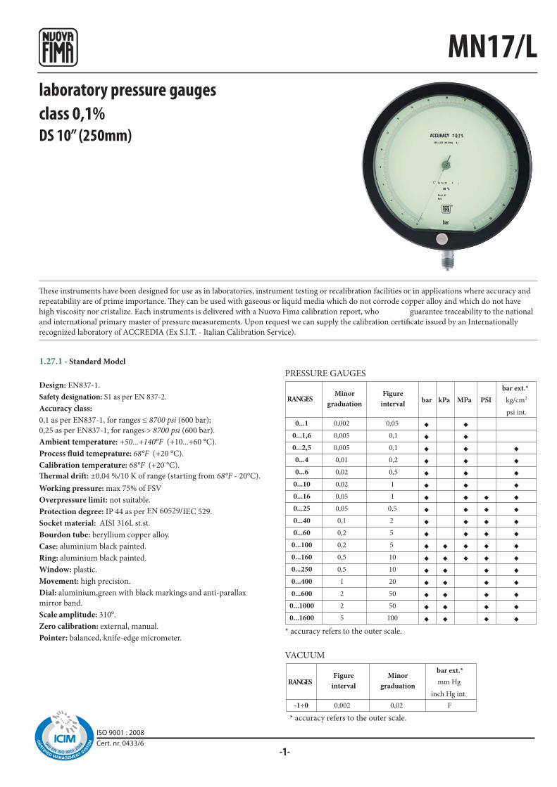
-1-
0,002
0,005
0,005
0,01
0,02
0,02
0,05
0,05
0,1
0,2
0,2
0,5
0,5
1
2
2
5
0,05
0,1
0,1
0,2
0,5
1
1
0,5
2
5
5
10
10
20
50
50
100
◆◆◆◆◆◆◆◆◆◆◆◆◆◆◆◆◆
◆◆◆◆◆◆◆
◆◆◆◆◆◆◆◆◆◆◆◆
◆◆◆◆◆◆◆◆◆◆◆
◆◆◆◆◆◆◆◆◆◆◆◆◆◆◆
0,002 0,02 F-1÷0
MN17/L
ISO 9001 : 2008Cert. nr. 0433/6
These instruments have been designed for use as in laboratories, instrument testing or recalibration facilities or in applications where accuracy and
repeatability are of prime importance. They can be used with gaseous or liquid media which do not corrode copper alloy and which do not have
high viscosity nor cristalize. Each instruments is delivered with a Nuova Fima calibration report, who guarantee traceability to the national
and international primary master of pressure measurements. Upon request we can supply the calibration certificate issued by an Internationally
recognized laboratory of ACCREDIA (Ex S.I.T. - Italian Calibration Service).
laboratory pressure gaugesclass 0,1%DS 10” (250mm)
1.27.1 - Standard Model
Design: EN837-1.
Safety designation: S1 as per EN 837-2.
Accuracy class:
0,1 as per EN837-1, for ranges ≤ 8700 psi (600 bar);
0,25 as per EN837-1, for ranges > 8700 psi (600 bar).
Ambient temperature: +50...+140°F (+10...+60 °C).
Process fluid temeprature: 68°F (+20 °C).
Calibration temperature: 68°F (+20 °C).
Thermal drift: ±0,04 %/10 K of range (starting from 68°F - 20°C).
Working pressure: max 75% of FSV
Overpressure limit: not suitable.
Protection degree: IP 44 as per EN 60529/IEC 529.
Socket material: AISI 316L st.st.
Bourdon tube: beryllium copper alloy.
Case: aluminium black painted.
Ring: aluminium black painted.
Window: plastic.
Movement: high precision.
Dial: aluminium,green with black markings and anti-parallax
mirror band.
Scale amplitude: 310°.
Zero calibration: external, manual.
Pointer: balanced, knife-edge micrometer.
PRESSURE GAUGES
VACUUM
* accuracy refers to the outer scale.
* accuracy refers to the outer scale.
RANGES
bar ext.*
mm Hg
inch Hg int.
Figure
interval
Minor
graduationRANGES
Figure
interval
Minor
graduationbar kPa MPa PSI kg/cm2
psi int.
bar ext.*
0...1
0...1,6
0...2,5
0...4
0...6
0...10
0...16
0...25
0...40
0...60
0...100
0...160
0...250
0...400
0...600
0...1000
0...1600

MN17/L
RC
8 -
05
/14
41M - G 1/2 A
41M - G 1/2 A
43M - 1/2-14 NPT
43M - 1/2-14 NPT
B -
CE1 -
CE3 -
K02 -
-2-
laboratory pressure gaugesclass 0,1%, DS 10” (250mm)
ACCREDIA certificate (pressure gauges)
ACCREDIA certificate (vacuum gauges)
Accuracy class 0,25% as per EN837-1, for ranges ≤ 600 bar
OPTIONS
dimensions : inches (mm)
Lower
Mounting
Back
F a b c d d1
e h p WeightL
(15)
0.59”
(15)
(63)
2.44”
(63)
(19,5)
0.76”(270)
10.62”
(270)
(247)
9.72”
(247)
(170)
6.69”(20)
0.78”
(20)
0.78”
(3,1 kg)
6.83 lbs
(3,25 kg)
1.47 lbs9.72”
ch
(17)(80)
3.14”(111,5)
3,72”0.59” 10.62”2.44” 0.66”
(17)
0.66”
A - LOWER CONNECTION
“HOW TO ORDER” SEQUENCE
Section / Model /Case / Mounting / Diameter / Range / Process connection / Options
1 27 1 A I 41M B...K02 D 43M
“U” Clamp (1)
(1) to be ordered for mounting cod. “D”
B - U” CLAMP,
for back connection
flush mounting
IN O
RD
ER
TO
IM
PR
OV
E T
HE
IR P
RO
DU
CT
ION
, ME
SSR
S. N
UO
VA
FIM
A R
ESE
RV
E T
HE
RIG
HT
TO
TH
EM
SELV
ES
TO
MA
KE
AL
L T
HE
MO
DIF
ICA
TIO
NS
TH
AT
TH
EY
DE
EM
IN
DIS
PE
NSA
BL
E A
T A
NY
TIM
E. U
PD
AT
ED
DA
TA
-SH
EE
TS
AR
E A
VA
ILA
BL
E O
N S
ITE
: ww
w.n
uo
vafi
ma.
com
NUOVA FIMA S.p.A. - www.nuovafima.comP.O. BOX 58 - VIA C. BATTISTI 59 - 28045 INVORIO (NO) ITALYTEL. +39 0322 253200 - FAX +39 0322 253232
Copyright © Nuova Fima srl. All rights reserved. Any part of this publication should not be reproduced without a written Nuova Fima’s srl approval
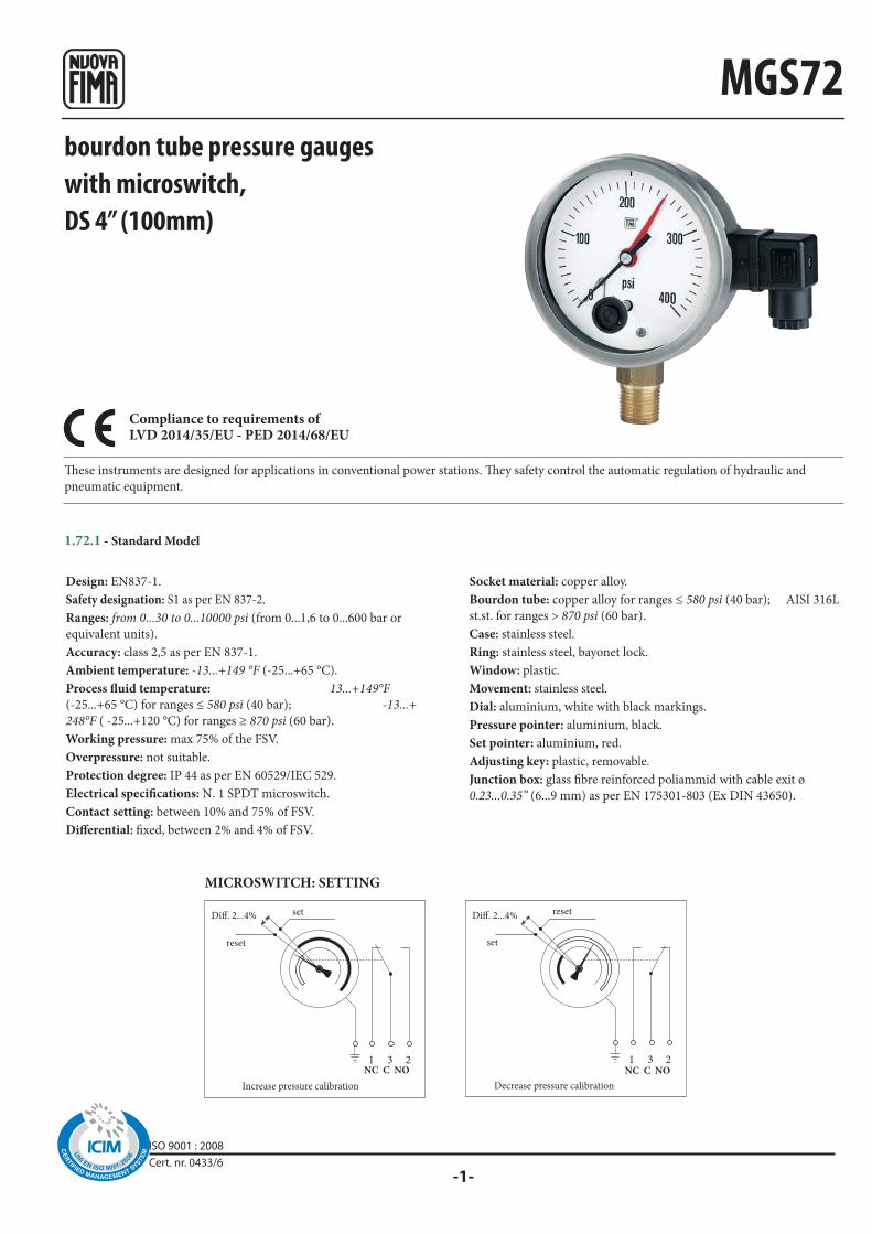
-1-
1 3 2 1 3 2
MGS72
Diff. 2...4% Diff. 2...4%
bourdon tube pressure gaugeswith microswitch,DS 4” (100mm)
These instruments are designed for applications in conventional power stations. They safety control the automatic regulation of hydraulic and
pneumatic equipment.
Design: EN837-1.
Safety designation: S1 as per EN 837-2.
Ranges: from 0...30 to 0...10000 psi (from 0...1,6 to 0...600 bar or
equivalent units).
Accuracy: class 2,5 as per EN 837-1.
Ambient temperature: -13...+149 °F (-25...+65 °C).
Process fluid temperature: 13...+149°F
(-25...+65 °C) for ranges ≤ 580 psi (40 bar); -13...+
248°F ( -25...+120 °C) for ranges ≥ 870 psi (60 bar).
Working pressure: max 75% of the FSV.
Overpressure: not suitable.
Protection degree: IP 44 as per EN 60529/IEC 529.
Electrical specifications: N. 1 SPDT microswitch.
Contact setting: between 10% and 75% of FSV.
Differential: fixed, between 2% and 4% of FSV.
Socket material: copper alloy.
Bourdon tube: copper alloy for ranges ≤ 580 psi (40 bar); AISI 316L
st.st. for ranges > 870 psi (60 bar).
Case: stainless steel.
Ring: stainless steel, bayonet lock.
Window: plastic.
Movement: stainless steel.
Dial: aluminium, white with black markings.
Pressure pointer: aluminium, black.
Set pointer: aluminium, red.
Adjusting key: plastic, removable.
Junction box: glass fibre reinforced poliammid with cable exit ø
0.23...0.35” (6...9 mm) as per EN 175301-803 (Ex DIN 43650).
Compliance to requirements ofLVD 2014/35/EU - PED 2014/68/EU
MICROSWITCH: SETTING
NC C NO
reset
set
Increase pressure calibration
set
NC C NO
reset
Decrease pressure calibration
1.72.1 - Standard Model
ISO 9001 : 2008Cert. nr. 0433/6
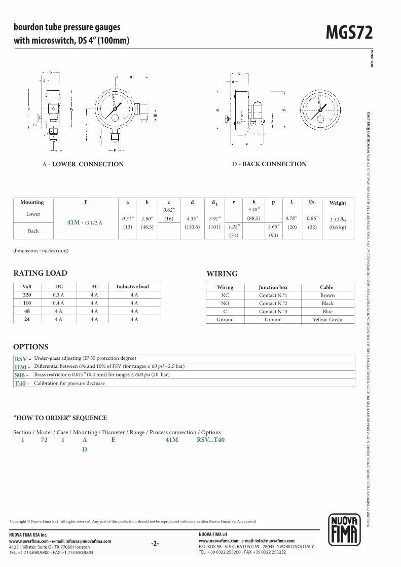
MGS72
Es.Es.
F
0,3 A
0,4 A
4 A
4 A
4 A
4 A
4 A
4 A
4 A
4 A
4 A
4 A
220
110
48
24
a b c d d1 e h p L Es.
RC2
- 08/
14
41M - G 1/2 A
RSV -
D30 - S06 -
T40 -
IN O
RD
ER
TO
IM
PR
OV
E T
HE
IR P
RO
DU
CT
ION
, ME
SSR
S. N
UO
VA
FIM
A R
ESE
RV
E T
HE
RIG
HT
TO
TH
EM
SELV
ES
TO
MA
KE
AL
L T
HE
MO
DIF
ICA
TIO
NS
TH
AT
TH
EY
DE
EM
IN
DIS
PE
NSA
BL
E A
T A
NY
TIM
E. U
PD
AT
ED
DA
TA
-SH
EE
TS
AR
E A
VA
ILA
BL
E O
N S
ITE
: ww
w.n
uo
vafi
ma.
com
Copyright © Nuova Fima S.r.l. All rights reserved. Any part of this publication should not be reproduced without a written Nuova Fima’s S.p.A. approval
bourdon tube pressure gaugeswith microswitch, DS 4” (100mm)
Mounting
Lower
Back
Weight
RATING LOAD WIRING
Inductive loadDC ACVolt
Contact N.°1
Contact N.°2
Contact N.°3
Ground
Brown
Black
Blue
Yellow-Green
NC
NO
C
Ground
Junction box CableWiring
OPTIONS
Under-glass adjusting (IP 55 protection degree)
Brass restrictor ø 0.015” (0,4 mm) for ranges ≤ 600 psi (40 bar)
Differential between 6% and 10% of FSV (for ranges ≥ 60 psi - 2,5 bar)
Calibration for pressure decrease
dimensions : inches (mm)
(0,6 kg)(13) (48,5)
0.62”
(110,6) (101) 1.22”
3.48”
3.65” (20) (22)
1.32 lbs0.51” 1.90” (16) 4.35” 3.97”
(31)
(88,5)
(90)
0.78” 0.86”
A - LOWER CONNECTION D - BACK CONNECTION
“HOW TO ORDER” SEQUENCE
Section / Model / Case / Mounting / Diameter / Range / Process connection / Options
1 72 1 A E 41M RSV...T40
D
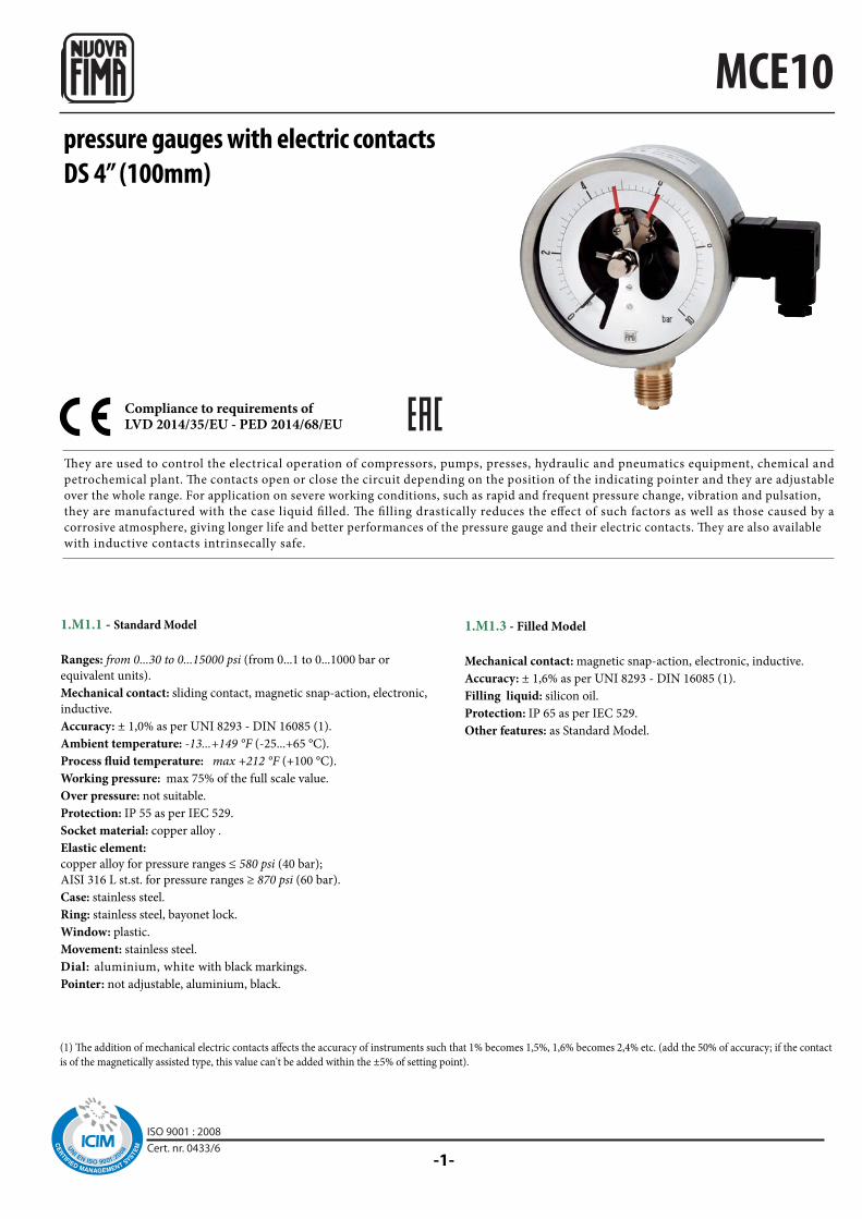
-1-
MCE10pressure gauges with electric contactsDS 4” (100mm)
They are used to control the electrical operation of compressors, pumps, presses, hydraulic and pneumatics equipment, chemical and
petrochemical plant. The contacts open or close the circuit depending on the position of the indicating pointer and they are adjustable
over the whole range. For application on severe working conditions, such as rapid and frequent pressure change, vibration and pulsation,
they are manufactured with the case liquid filled. The filling drastically reduces the effect of such factors as well as those caused by a
corrosive atmosphere, giving longer life and better performances of the pressure gauge and their electric contacts. They are also available
with inductive contacts intrinsecally safe.
(1) The addition of mechanical electric contacts affects the accuracy of instruments such that 1% becomes 1,5%, 1,6% becomes 2,4% etc. (add the 50% of accuracy; if the contact
is of the magnetically assisted type, this value can't be added within the ±5% of setting point).
Compliance to requirements ofLVD 2014/35/EU - PED 2014/68/EU
1.M1.1 - Standard Model
Ranges: from 0...30 to 0...15000 psi (from 0...1 to 0...1000 bar or
equivalent units).
Mechanical contact: sliding contact, magnetic snap-action, electronic,
inductive.
Accuracy: ± 1,0% as per UNI 8293 - DIN 16085 (1).
Ambient temperature: -13...+149 °F (-25...+65 °C).
Process fluid temperature: max +212 °F (+100 °C).
Working pressure: max 75% of the full scale value.
Over pressure: not suitable.
Protection: IP 55 as per IEC 529.
Socket material: copper alloy .
Elastic element:
copper alloy for pressure ranges ≤ 580 psi (40 bar);
AISI 316 L st.st. for pressure ranges ≥ 870 psi (60 bar).
Case: stainless steel.
Ring: stainless steel, bayonet lock.
Window: plastic.
Movement: stainless steel.
Dial: aluminium, white with black markings.
Pointer: not adjustable, aluminium, black.
1.M1.3 - Filled Model
Mechanical contact: magnetic snap-action, electronic, inductive.
Accuracy: ± 1,6% as per UNI 8293 - DIN 16085 (1).
Filling liquid: silicon oil.
Protection: IP 65 as per IEC 529.
Other features: as Standard Model.
ISO 9001 : 2008Cert. nr. 0433/6
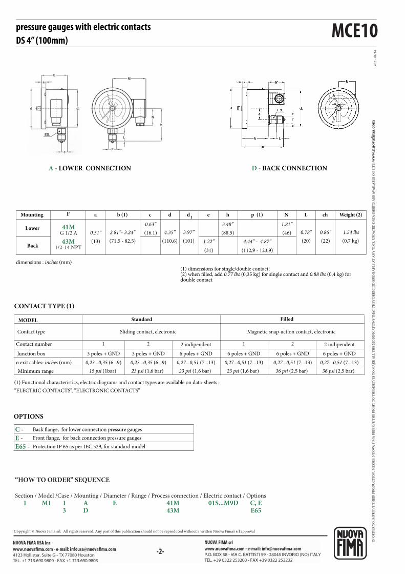
MCE10
RC
2 -
08
/14
F
1 12 2
41MG 1/2 A
43M1/2-14 NPT
C -
E -
E65 -
chLNp (1)ed1
db (1)a hc
pressure gauges with electric contactsDS 4” (100mm)
(1) dimensions for single/double contact; (2) when filled, add 0.77 lbs (0,35 kg) for single contact and 0.88 lbs (0,4 kg) for double contact
dimensions : inches (mm)
Mounting
Lower
Back
Weight (2)
(0,7 kg)
1.54 lbs(22)
0.86”(20)
0.78”(46)
1.81”
(112,9 - 123,9)
4.44” - 4.87”(31)
1.22”(101)
3.97”(110,6)
4.35”(71,5 - 82,5)
2.81”- 3.24”(13)
0.51” (88,5)
3.48”(16.1)
0.63”
OPTIONS
Back flange, for lower connection pressure gauges
Front flange, for back connection pressure gauges
Protection IP 65 as per IEC 529, for standard model
(1) Functional characteristics, electric diagrams and contact types are available on data-sheets :
“ELECTRIC CONTACTS”, “ELECTRONIC CONTACTS”
CONTACT TYPE (1)
Contact type
MODEL
Contact number
Minimum range
Magnetic snap-action contact, electronic
Filled
Sliding contact, electronic
Standard
15 psi (1bar) 23 psi (1,6 bar)23 psi (1,6 bar) 36 psi (2,5 bar)23 psi (1,6 bar) 36 psi (2,5 bar)
Junction box 3 poles + GND 3 poles + GND 6 poles + GND 6 poles + GND 6 poles + GND 6 poles + GND
ø exit cables: inches (mm) 0,23...0,35 (6...9) 0,23...0,35 (6...9) 0,27...0,51 (7...13) 0,27...0,51 (7...13) 0,27...0,51 (7...13) 0,27...0,51 (7...13)
2 indipendent 2 indipendent
A - LOWER CONNECTION D - BACK CONNECTION
“HOW TO ORDER” SEQUENCE
Section / Model /Case / Mounting / Diameter / Range / Process connection / Electric contact / Options
1 M1 1 A E 41M 01S...M9D C, E 3 D 43M E65
IN O
RD
ER
TO
IM
PR
OV
E T
HE
IR P
RO
DU
CT
ION
, ME
SSR
S. N
UO
VA
FIM
A R
ESE
RV
E T
HE
RIG
HT
TO
TH
EM
SELV
ES
TO
MA
KE
AL
L T
HE
MO
DIF
ICA
TIO
NS
TH
AT
TH
EY
DE
EM
IN
DIS
PE
NSA
BL
E A
T A
NY
TIM
E. U
PD
AT
ED
DA
TA
-SH
EE
TS
AR
E A
VA
ILA
BL
E O
N S
ITE
: ww
w.n
uo
vafi
ma.
com
NUOVA FIMA S.p.A. - www.nuovafima.comP.O. BOX 58 - VIA C. BATTISTI 59 - 28045 INVORIO (NO) ITALYTEL. +39 0322 253200 - FAX +39 0322 253232
Copyright © Nuova Fima srl. All rights reserved. Any part of this publication should not be reproduced without a written Nuova Fima’s srl approval

-1-
MN14/10pressure gauges with electric contactsDS 4”, 6” (100-150 mm)
(1) The addition of mechanical electric contacts affects the accuracy of instruments such that 1% becomes 1,5%, 1,6% becomes 2,4% etc. (add the 50% of
accuracy; if the contact is of the magnetically assisted type, this value can't be added within the ±5% of setting point).
1.M7.1 - Standard Model
Ranges: from 0...30 to 0...15000 psi (from 0...1.6 to 0...1000 bar or
equivalent units).
Mechanical contact: sliding contact, magnetic snap-action,
electronic, inductive.
Accuracy: ± 1,0% as per EN 837-1 - DIN 16085 (1).
Ambient temperature: -13...+149 °F (-25...+65 °C).
Process fluid temperature: max +149°F (+65 °C).
Working pressure: max 75% of the full scale value.
Over pressure: not suitable.
Protection: IP 44 as per EN 60529/IEC 529.
Socket material: copper alloy .
Elastic element:
copper alloy for pressure ranges ≤ 580 psi (40 bar);
AISI 316 L st.st. for pressure ranges ≥ 870 psi (60 bar).
Case: stainless steel.
Ring: stainless steel, bayonet lock.
Window: plastic.
Movement: stainless steel.
Dial: aluminium, white with black markings.
Pointer: not adjustable, aluminium, black
Alarm contacts are accessories with movable contacts in air, which open or close electric circuits depending of the position of the indicating pointer.
They are used with Bourdon tube pressure gauges, bellows, diaphragm and thermometers of NUOVA FIMA production, in such way they become
pressure and temperature switches: the optimal and sure solution to automatize any kind of equipment.
Compliance to requirements ofLVD 2014/35/EU - PED 2014/68/EU
ISO 9001 : 2008Cert. nr. 0433/6
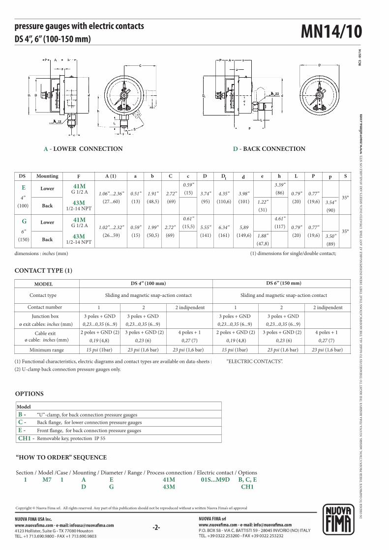
MN14/10
F SL peD1 dbA (1) c PDa C h
1 12 2
RC3
- 05/
14
E
G
CH1 -
B - C -
E -
41MG 1/2 A
43M1/2-14 NPT
41MG 1/2 A
43M1/2-14 NPT
pressure gauges with electric contactsDS 4”, 6” (100-150 mm)
dimensions : inches (mm) (1) dimensions for single/double contact;
DS Mounting
Lower
Back
Lower
Back
35°
35°
(20)
(20)
0.79”
0.79”
(90)
(89)
3.54”
3.50”
(31)
(47,8)
1.22”
1.88”
(110,6)
(161)
4.35”
6.34”
(101)
(149,6)
3.98”
5,89
(48,5)
(50,5)
1.91”
1.99”
(27...60)
(26...59)
1.06”...2.36”
1.02”...2.32”
(86)
(117)
3.39”
4.61”
(15)
(15,5)
0.59”
0.61”
(19,6)
(19,6)
0.77”
0.77”
(95)
(141)
3.74”
5.55”
(13)
(15)
0.51”
0.59”
(69)
(69)
2.72”
2.72”
(100)
(150)
4”
6”
Model
Removable key, protection IP 55
OPTIONS
“U”-clamp, for back connection pressure gauges
Back flange, for lower connection pressure gauges
Front flange, for back connection pressure gauges
(1) Functional characteristics, electric diagrams and contact types are available on data-sheets : “ELECTRIC CONTACTS”.
(2) U-clamp back connection pressure gauges only.
CONTACT TYPE (1)
Contact type
MODEL
Contact number
Minimum range
Sliding and magnetic snap-action contact
DS 6” (150 mm)
Sliding and magnetic snap-action contact
DS 4” (100 mm)
15 psi (1bar) 15 psi (1bar)23 psi (1,6 bar) 23 psi (1,6 bar)23 psi (1,6 bar) 23 psi (1,6 bar)
Junction box 3 poles + GND 3 poles + GND 3 poles + GND 3 poles + GND
ø exit cables: inches (mm) 0,23...0,35 (6...9) 0,23...0,35 (6...9) 0,23...0,35 (6...9) 0,23...0,35 (6...9)
2 indipendent 2 indipendent
Cable exit 4 poles + 1
ø cable: inches (mm) 0,27 (7)
3 poles + GND (2)
0,23 (6)
2 poles + GND (2)
0,19 (4,8)
4 poles + 1
0,27 (7)0,23 (6)0,19 (4,8)
3 poles + GND (2)2 poles + GND (2)
A - LOWER CONNECTION D - BACK CONNECTION
“HOW TO ORDER” SEQUENCE
Section / Model /Case / Mounting / Diameter / Range / Process connection / Electric contact / Options
1 M7 1 A E 41M 01S...M9D B, C, E D G 43M CH1
IN O
RD
ER
TO
IM
PR
OV
E T
HE
IR P
RO
DU
CT
ION
, ME
SSR
S. N
UO
VA
FIM
A R
ESE
RV
E T
HE
RIG
HT
TO
TH
EM
SELV
ES
TO
MA
KE
AL
L T
HE
MO
DIF
ICA
TIO
NS
TH
AT
TH
EY
DE
EM
IN
DIS
PE
NSA
BL
E A
T A
NY
TIM
E. U
PD
AT
ED
DA
TA
-SH
EE
TS
AR
E A
VA
ILA
BL
E O
N S
ITE
: ww
w.n
uo
vafi
ma.
com
Copyright © Nuova Fima srl. All rights reserved. Any part of this publication should not be reproduced without a written Nuova Fima’s srl approval
NUOVA FIMA S.p.A. - www.nuovafima.comP.O. BOX 58 - VIA C. BATTISTI 59 - 28045 INVORIO (NO) ITALYTEL. +39 0322 253200 - FAX +39 0322 253232
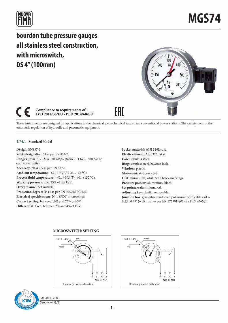
-1-
1 3 2 1 3 2
Diff. 2 ...4% Diff. 2 ...4%
MGS74bourdon tube pressure gaugesall stainless steel construction,with microswitch,DS 4” (100mm)
These instruments are designed for applications in the chemical, petrochemical industries, conventional power stations. They safety control the
automatic regulation of hydraulic and pneumatic equipment.
Design: EN837-1.
Safety designation: S1 as per EN 837-2.
Ranges: from 0...15 to 0...10000 psi (from 0...1 to 0...600 bar or
equivalent units).
Accuracy: class 2,5 as per EN 837-1.
Ambient temperature: -13...+149 °F (-25...+65 °C).
Process fluid temperature: -40...+302 °F (-40...+150 °C).
Working pressure: max 75% of the FSV.
Overpressure: not suitable.
Protection degree: IP 44 as per EN 60529/IEC 529.
Electrical specifications: N. 1 SPDT microswitch.
Contact setting: between 10% and 75% of FSV.
Differential: fixed, between 2% and 4% of FSV.
Socket material: AISI 316L st.st.
Elastic element: AISI 316L st.st.
Case: stainless steel.
Ring: stainless steel, bayonet lock.
Window: plastic.
Movement: stainless steel.
Dial: aluminium, white with black markings.
Pressure pointer: aluminium, black.
Set pointer: aluminium, red.
Adjusting key: plastic, removable.
Junction box: glass fibre reinforced poliammid with cable exit ø
0.23...0.35” (6...9 mm) as per EN 175301-803 (Ex DIN 43650).
MICROSWITCH: SETTING
NC C NO
reset
set
Increase pressure calibration
set
NC C NO
reset
Decrease pressure calibration
1.74.1 - Standard Model
Compliance to requirements ofLVD 2014/35/EU - PED 2014/68/EU
ISO 9001 : 2008Cert. nr. 0433/6
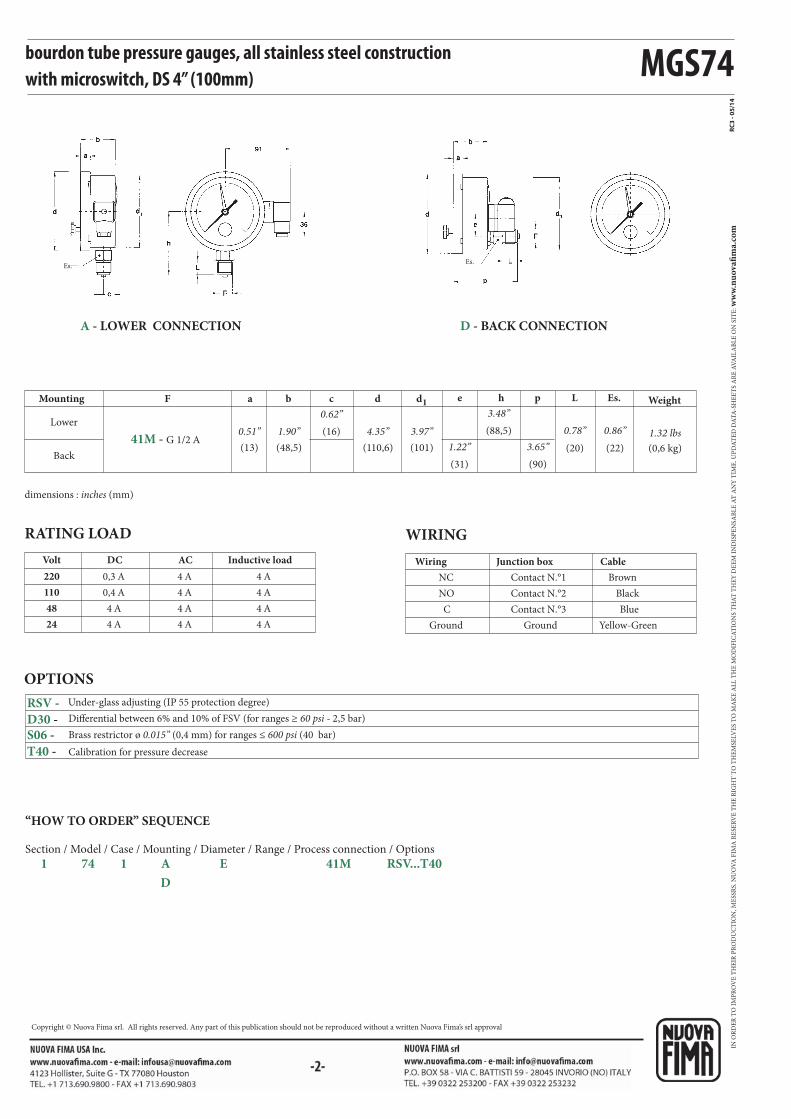
MGS74
Es.Es.
0,3 A
0,4 A
4 A
4 A
4 A
4 A
4 A
4 A
4 A
4 A
4 A
4 A
220
110
48
24
F a b c d d1 e h p L Es.
RC3
- 05/
14
41M - G 1/2 A
RSV -
D30 - S06 -
T40 -
bourdon tube pressure gauges, all stainless steel constructionwith microswitch, DS 4” (100mm)
RATING LOAD WIRING
Inductive loadDC ACVolt
Contact N.°1
Contact N.°2
Contact N.°3
Ground
Brown
Black
Blue
Yellow-Green
NC
NO
C
Ground
Junction box CableWiring
OPTIONS
Brass restrictor ø 0.015” (0,4 mm) for ranges ≤ 600 psi (40 bar)
Differential between 6% and 10% of FSV (for ranges ≥ 60 psi - 2,5 bar)
Calibration for pressure decrease
Mounting
Lower
Back
Weight
dimensions : inches (mm)
(0,6 kg)(13) (48,5)
0.62”
(110,6) (101) 1.22”
3.48”
3.65” (20) (22)
1.32 lbs0.51” 1.90” (16) 4.35” 3.97”
(31)
(88,5)
(90)
0.78” 0.86”
A - LOWER CONNECTION D - BACK CONNECTION
“HOW TO ORDER” SEQUENCE
Section / Model / Case / Mounting / Diameter / Range / Process connection / Options
1 74 1 A E 41M RSV...T40
D
Under-glass adjusting (IP 55 protection degree)
IN O
RD
ER
TO
IM
PR
OV
E T
HE
IR P
RO
DU
CT
ION
, ME
SSR
S. N
UO
VA
FIM
A R
ESE
RV
E T
HE
RIG
HT
TO
TH
EM
SELV
ES
TO
MA
KE
AL
L T
HE
MO
DIF
ICA
TIO
NS
TH
AT
TH
EY
DE
EM
IN
DIS
PE
NSA
BL
E A
T A
NY
TIM
E. U
PD
AT
ED
DA
TA
-SH
EE
TS
AR
E A
VA
ILA
BL
E O
N S
ITE
: ww
w.n
uo
vafi
ma.
com
NUOVA FIMA S.p.A. - www.nuovafima.comP.O. BOX 58 - VIA C. BATTISTI 59 - 28045 INVORIO (NO) ITALYTEL. +39 0322 253200 - FAX +39 0322 253232
Copyright © Nuova Fima srl. All rights reserved. Any part of this publication should not be reproduced without a written Nuova Fima’s srl approval

-1-
MCE18pressure gauges with electric contactsall stainless steel constructionDS 4” (100mm)
They are used to control the electrical operation of compressors, pumps, presses, hydraulic and pneumatics equipment, chemical and petrochemical
plant. The contacts open or close the circuit depending on the position of the indicating pointer and they are adjustable over the whole range. For
application on severe working conditions, such as rapid and frequent pressure change, vibration and pulsation, they are manufactured with the case
liquid filled. The filling drastically reduces the effect of such factors as well as those caused by a corrosive atmosphere, giving longer life and better
performances of the pressure gauge and their electric contacts. They are also available with inductive contacts intrinsecally safe.
(1) The addition of mechanical electric contacts affects the accuracy of instruments such that 1% becomes 1,5%, 1,6% becomes 2,4% etc. (add the 50%
of accuracy; if the contact is of the magnetically assisted type, this value can't be added within the ±5% of setting point).
1.M2.1 - Standard Model
Ranges: from 0...15 to 0...20000 psi (from 0...1 to 0...1600 bar or
equivalent units).
Mechanical contact: sliding contact, magnetic snap-action, electronic,
inductive.
Accuracy: ± 1,0% as per EN 837-1 - DIN 16085 (1).
Ambient temperature: -13...+149 °F (-25...+65 °C).
Process fluid temperature: max +212 °F (+100 °C).
Working pressure: max 75% of the full scale value.
Over pressure: not suitable.
Protection: IP 55 as per EN 60529/IEC 529.
Socket material: AISI 316L st.st.
Elastic element: AISI 316L st.st.
Case: stainless steel.
Ring: stainless steel, bayonet lock.
Window: plastic.
Movement: stainless steel.
Dial: aluminium, white with black markings.
Pointer: not adjustable, aluminium, black.
1.M2.3 - Filled Model
Mechanical contact: magnetic snap-action, electronic, inductive.
Accuracy: ± 1,6% as per EN 837-1 - DIN 16085 (1).
Process fluid temperature: max +149 °F (+65 °C).
Filling liquid: silicon oil.
Protection: IP 65 as per EN 60529/IEC 529.
Other features: as Standard Model.
Compliance to requirements ofLVD 2014/35/EU - PED 2014/68/EU
ISO 9001 : 2008Cert. nr. 0433/6
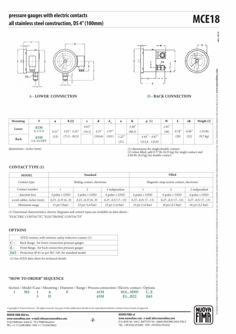
RC3
- 05/
14
F chLNp (1)ed1
db (1)a hc
MCE18
1 12 2
41MG 1/2 A
C -
E -
E65 -
43M1/2-14 NPT
pressure gauges with electric contactsall stainless steel construction, DS 4” (100mm)
dimensions : inches (mm) (1) dimensions for single/double contact; (2) when filled, add 0.77 lbs (0,35 kg) for single contact and 0.88 lbs (0,4 kg) for double contact
Mounting
Lower
Back
Weight (2)
(0,7 kg)
1.54 lbs(22)
ch
0.86”(20)
L
0.78”(46)
N
1.81”
(112,9 - 123,9)
4.44” - 4.87”(31)
e
1.22”(101)
3.97”(110,6)
d
4.35”(71,5 - 82,5)
b (1)
2.81”- 3.24”(13)
a
0.51” (88,5)
h
3.48”(16.1)
c
0.63”
(1) Functional characteristics, electric diagrams and contact types are available on data-sheets :
“ELECTRIC CONTACTS”, “ELECTRONIC CONTACTS”
CONTACT TYPE (1)
Contact type
MODEL
Contact number
Minimum range
Magnetic snap-action contact, electronic
Filled
Sliding contact, electronic
Standard
15 psi (1bar) 23 psi (1,6 bar)23 psi (1,6 bar) 36 psi (2,5 bar)23 psi (1,6 bar) 36 psi (2,5 bar)
Junction box 3 poles + GND 3 poles + GND 6 poles + GND 6 poles + GND 6 poles + GND 6 poles + GND
ø exit cables: inches (mm) 0,23...0,35 (6...9) 0,23...0,35 (6...9) 0,27...0,51 (7...13) 0,27...0,51 (7...13) 0,27...0,51 (7...13) 0,27...0,51 (7...13)
2 indipendent 2 indipendent
OPTIONS
Front flange, for back connection pressure gauges
Protection IP 65 as per IEC 529, for standard model
Back flange, for lower connection pressure gauges
ATEX version, with intrinsic safety inductive contact (1)
(1) See ATEX data-sheet for technical details
A - LOWER CONNECTION D - BACK CONNECTION
“HOW TO ORDER” SEQUENCE
Section / Model /Case / Mounting / Diameter / Range / Process connection / Electric contact / Options
1 M2 1 A E 41M 01S...M9D C, E 3 D 43M E1...B22 E65
IN O
RD
ER
TO
IM
PR
OV
E T
HE
IR P
RO
DU
CT
ION
, ME
SSR
S. N
UO
VA
FIM
A R
ESE
RV
E T
HE
RIG
HT
TO
TH
EM
SELV
ES
TO
MA
KE
AL
L T
HE
MO
DIF
ICA
TIO
NS
TH
AT
TH
EY
DE
EM
IN
DIS
PE
NSA
BL
E A
T A
NY
TIM
E. U
PD
AT
ED
DA
TA
-SH
EE
TS
AR
E A
VA
ILA
BL
E O
N S
ITE
: ww
w.n
uo
vafi
ma.
com
NUOVA FIMA S.p.A. - www.nuovafima.comP.O. BOX 58 - VIA C. BATTISTI 59 - 28045 INVORIO (NO) ITALYTEL. +39 0322 253200 - FAX +39 0322 253232
Copyright © Nuova Fima srl. All rights reserved. Any part of this publication should not be reproduced without a written Nuova Fima’s srl approval
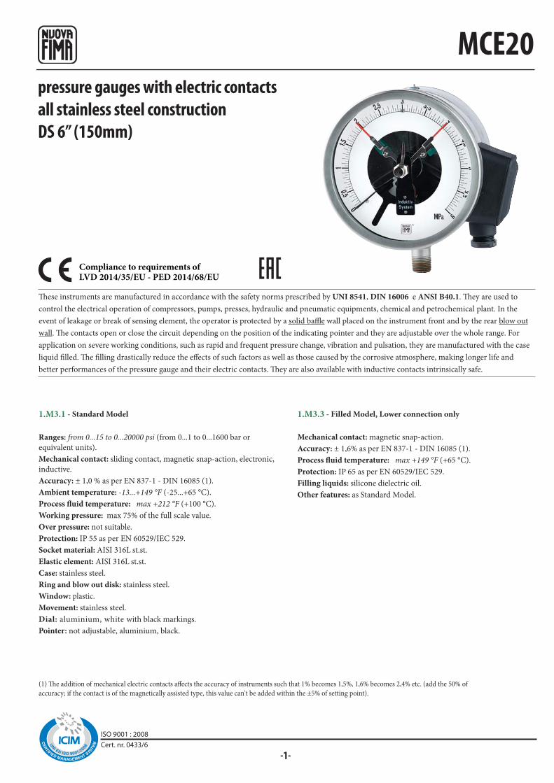
-1-
MCE20pressure gauges with electric contactsall stainless steel constructionDS 6” (150mm)
1.M3.1 - Standard Model
Ranges: from 0...15 to 0...20000 psi (from 0...1 to 0...1600 bar or
equivalent units).
Mechanical contact: sliding contact, magnetic snap-action, electronic,
inductive.
Accuracy: ± 1,0 % as per EN 837-1 - DIN 16085 (1).
Ambient temperature: -13...+149 °F (-25...+65 °C).
Process fluid temperature: max +212 °F (+100 °C).
Working pressure: max 75% of the full scale value.
Over pressure: not suitable.
Protection: IP 55 as per EN 60529/IEC 529.
Socket material: AISI 316L st.st.
Elastic element: AISI 316L st.st.
Case: stainless steel.
Ring and blow out disk: stainless steel.
Window: plastic.
Movement: stainless steel.
Dial: aluminium, white with black markings.
Pointer: not adjustable, aluminium, black.
1.M3.3 - Filled Model, Lower connection only
Mechanical contact: magnetic snap-action.
Accuracy: ± 1,6% as per EN 837-1 - DIN 16085 (1).
Process fluid temperature: max +149 °F (+65 °C).
Protection: IP 65 as per EN 60529/IEC 529.
Filling liquids: silicone dielectric oil.
Other features: as Standard Model.
(1) The addition of mechanical electric contacts affects the accuracy of instruments such that 1% becomes 1,5%, 1,6% becomes 2,4% etc. (add the 50% of
accuracy; if the contact is of the magnetically assisted type, this value can't be added within the ±5% of setting point).
These instruments are manufactured in accordance with the safety norms prescribed by UNI 8541, DIN 16006 e ANSI B40.1. They are used to
control the electrical operation of compressors, pumps, presses, hydraulic and pneumatic equipments, chemical and petrochemical plant. In the
event of leakage or break of sensing element, the operator is protected by a solid baffle wall placed on the instrument front and by the rear blow out
wall. The contacts open or close the circuit depending on the position of the indicating pointer and they are adjustable over the whole range. For
application on severe working conditions, such as rapid and frequent pressure change, vibration and pulsation, they are manufactured with the case
liquid filled. The filling drastically reduce the effects of such factors as well as those caused by the corrosive atmosphere, making longer life and
better performances of the pressure gauge and their electric contacts. They are also available with inductive contacts intrinsically safe.
Compliance to requirements ofLVD 2014/35/EU - PED 2014/68/EU
ISO 9001 : 2008Cert. nr. 0433/6

MCE20
F LNped1
dba hc chM
RC3 -
05/1
4
1 2 1 2
41MG 1/2 A
C -
P02 -
E65 -
pressure gauges with electric contactsall stainless steel construction, DS 6” (150mm)
(1) when filled, add 3.63 lbs (1,65 kg)dimensions : inches (mm)
Mounting
Lower
Back(20)
L
0.78”
(83)
N
3.27”
(160)
6,30”(47,8)
e
1.88”(149,5)
5.89”(161)
d
6.34”(127)
b
5”(15)
a
0.59” (118)
h
4.65”(30)
c
1.18”(24)
ch
0.94”
(17)
0.67”
Weight (1)
1,45 kg)
3.19 lbs
(1,4 kg)
3.08 lbs(110)
4.33”
OPTIONS
Back flange, for lower connection pressure gauges
Oxygen service
Protection IP 65 as per IEC 529, for standard model
(1) Functional characteristics, electric diagrams and contact types are available on data-sheets : “ELECTRIC CONTACTS”.
CONTACT TYPE (1)
Magnetic snap-action contact
Filled
Sliding contact
Standard
Contact type
MODEL
Contact number
Minimum range
Junction box
ø exit cables: inches (mm)
15 psi (1bar)
4 poles + GND
0,35...0,55 (9...14)
23 psi (1,6 bar)
4 poles + GND
0,35...0,55 (9...14)
23 psi (1,6 bar)
4 poles + GND
0,35...0,55 (9...14)
36 psi (2,5 bar)
4 poles + GND
0,35...0,55 (9...14)
A - LOWER CONNECTION D - BACK CONNECTION
“HOW TO ORDER” SEQUENCE
Section / Model /Case / Mounting / Diameter / Range / Process connection / Electric contact / Options
1 M3 1 A G 41M 01S...M9D C 3 D P02, E65
IN O
RD
ER
TO
IM
PR
OV
E T
HE
IR P
RO
DU
CT
ION
, ME
SSR
S. N
UO
VA
FIM
A R
ESE
RV
E T
HE
RIG
HT
TO
TH
EM
SELV
ES
TO
MA
KE
AL
L T
HE
MO
DIF
ICA
TIO
NS
TH
AT
TH
EY
DE
EM
IN
DIS
PE
NSA
BL
E A
T A
NY
TIM
E. U
PD
AT
ED
DA
TA
-SH
EE
TS
AR
E A
VA
ILA
BL
E O
N S
ITE
: ww
w.n
uo
vafi
ma.
com
NUOVA FIMA S.p.A. - www.nuovafima.comP.O. BOX 58 - VIA C. BATTISTI 59 - 28045 INVORIO (NO) ITALYTEL. +39 0322 253200 - FAX +39 0322 253232
Copyright © Nuova Fima srl. All rights reserved. Any part of this publication should not be reproduced without a written Nuova Fima’s srl approval

MCE10-18/SF6
-1-
Pressure gaugesfor SF6 gas monitoringDS 4” (100 mm)
These instruments are manufactured to monitor the electrical operations on hermetically sealed systems containing Sulphur Hexafluoride gas (SF6). The indication and the electrical operations are calibrated to the gas density (isochore) according to the relation pressure-temperature. The M5 model is suitable for indoor installation while the M6 model has been designed for the outdoor installation as well. The oil filled executions are particularly suitable for installation when vibrations are apparent.
Accuracy of indication (referred to the instruments range): ±1% at +20 °C of ambient temperature; ±2,5% within the temperature range -20...+60°C related to the calibration pressure of the reference isochore.Accuracy of intervention: - see accuracy of indication for set-point equal to pressure of calibration; - when set-point is different from pressure of calibration, calculate it according to the instrument range.
Alarm contacts, non adjustable contacts, with antitampering sealing: - on air with magnetic block (80%Ag-20%Ni);
- inductive with galvanic exit. Ambient temperature: -20...+60 °C.Storage temperature: -40...+60°CCalibration pressure (PC): refer to order specifications.Ranges: also vacuum & compound gauges from 1,6 to 25 bar.Electrical connection: junction box with cable gland M20 x 1,5.
Nominal diameter: DN100.Gas seal: leakage rate ≤ 1x10⁻⁶ mbar x l/s-1 (helium test with mass spectrometer).Case: AISI 304.Ring: bayonet lock, AISI 304 with antitampering sealing.Window: glass.Movement: stainless steel with bimetallic temperature compensator.Dial: white aluminium with black markings and coloured sectors as per customer’s specification.Pointer: black anodised aluminium.
1 - Standard dry version
Process connection: OT58.Sensing element: phosphor bronze.Protection degree: IP 54 as per IEC 529, UNI 8896.
3 - Silicon oil filled version
Process connection: OT58.Sensing element: phosphor bronze.Protection degree: IP65 as per IEC 529, UNI 8896.Window: safety glass.
1 - Standard dry version
Process connection and sensing element: AISI 316L.Protection degree: IP 54 as per IEC 529, UNI 8896.
3 - Silicon oil filled version
Process connection and sensing element: AISI 316L.Protection degree: IP 65 as per IEC 529, UNI 8896.Window: safety glass.
9 - Nitrogen filled version
Process connection and sensing element: AISI 316L.Protection degree: IP 65 as per IEC 529, UNI 8896.Window: safety glass.
1.M5 - MCE10/SF6 : copper alloy wetted parts , suitable for
indoor ambients
1.M6 - MCE18/SF6 : AISI 316L wetted parts, suitable for
outdoor ambients
Compliance to requirements ofLVD 2014/35/EU - PED 2014/68/EU
ISO 9001 : 2008Cert. nr. 0433/6
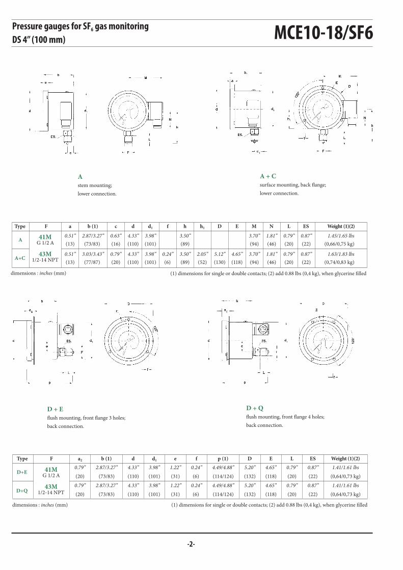
-2-
MCE10-18/SF6
A
A+C
D+E
D+Q
ESLNMEDhfd1dcb (1)aF
F ESLEDp (1)fed1db (1)a2
h1
41MG 1/2 A
43M1/2-14 NPT
41MG 1/2 A
43M1/2-14 NPT
Pressure gauges for SF6 gas monitoringDS 4” (100 mm)
A
stem mounting;
lower connection.
A + C
surface mounting, back flange;
lower connection.
D + Q
flush mounting, front flange 4 holes;
back connection.
D + E
flush mounting, front flange 3 holes;
back connection.
(1) dimensions for single or double contacts; (2) add 0.88 lbs (0,4 kg), when glycerine filleddimensions : inches (mm)
Weight (1)(2)
(0,66/0,75 kg)
(0,74/0,83 kg)
1.45/1.65 lbs
1.63/1.83 lbs
Type
(22)
(22)
0.87”
0.87”
(20)
(20)
0.79”
0.79”
(46)
(46)
1.81”
1.81”
(94)
(94)
3.70”
3.70”(118)
4.65”(130)
5.12”
(89)
(89)
3.50”
3.50”(6)
0.24”
(101)
(101)
3.98”
3.98”
(110)
(110)
4.33”
4.33”
(16)
(20)
0.63”
0.79”
(73/83)
(77/87)
2.87/3.27”
3.03/3.43”
(13)
(13)
0.51”
0.51”(52)
2.05”
Type
(1) dimensions for single or double contacts; (2) add 0.88 lbs (0,4 kg), when glycerine filleddimensions : inches (mm)
Weight (1)(2)
1.41/1.61 lbs
1.41/1.61 lbs(0,64/0,73 kg)
(0,64/0,73 kg)
0.87”
0.87”(22)
(22)
0.79”
0.79”(20)
(20)
4.65”
4.65”(118)
(118)
5.20”
5.20”(132)
(132)
4.49/4.88”
4.49/4.88”(114/124)
(114/124)
0.24”
0.24”(6)
(6)
1.22”
1.22”(31)
(31)
3.98”
3.98”(101)
(101)
4.33”
4.33”(110)
(110)
2.87/3.27”
2.87/3.27”(73/83)
(73/83)
0.79”
0.79”(20)
(20)
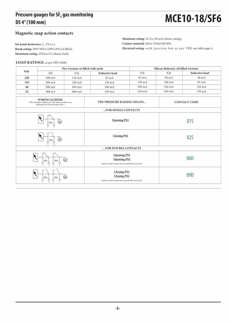
-3-
65 mA
130 mA
200 mA
250 mA
120 mA
240 mA
450 mA
600 mA
100 mA
200 mA
300 mA
400 mA
220
110
48
24
65 mA
130 mA
190 mA
250 mA
90 mA
180 mA
330 mA
450 mA
40 mA
85 mA
130 mA
150 mA
01S
1 2
PS1
1 23 4
PS1PS2
1 23 4
PS1PS2
1 2
PS1
02S
06D
09D
MCE10-18/SF6Pressure gauges for SF6 gas monitoringDS 4” (100 mm)
Magnetic snap action contacts
Set-point hysteresys: 2...5% f.s.v.
Break rating: 30W/50VA (20W/20VA if filled).
Maximum rating: 250Vca/1A (ohmic load).
Minimum rating: 24 Vcc/20 mA (ohmic rating).
Contact material: Silver-Nickel 80/20%.
Electrical wiring: w it h j u n c t i on b ox a s p e r VDE, see table page 4.
LOAD RATINGS, as per DIN 16085.
Silicon dielectric oil filled versionsDry versions or filled with azoteVolt
Inductive loadCACC CC CA Inductive load
...FOR SINGLE CONTACTS
... FOR DOUBLE CONTACTS
CONTACT CODETHE PRESSURE RAISING MEANS...
Opening PS1
WIRING SCHEME(The numbers shown are the same as those are
indicated on the junction box )
Closing PS1
Opening PS1
Opening PS2
(each contact must not exceed the next one)
Closing PS1
Closing PS2
(each contact must not exceed the next one)

bar
MPa
MCE10-18/SF6
RC3 -
02/1
6
Pressure gauges for SF6 gas monitoringDS 4” (100 mm)
RANGES
RECOMMENDATION
The measuring of the temperature necessary to the termic compensation it is detected inside the instrument. This means that these instruments
should be installed so that their operating temperature corresponds to the one of the monitored SF6 gas.
In order to avoid any compensating error due to the different isochores, the PC calibration must be as nearest as possible to the PS contacts
setting pressure.
HOW TO ORDER
PS2 - setting pressure of the contactPS2, on the temperature
of SF6 gas of 20°C
...and if the contacts are two
PF - nominal pressure of the circuit filling
2° - CALIBRATION FEATURES
PC - calibration pressure, which identifies the reference
isochore
PS1 - setting pressure of the contact PS1, on the temperature
of SF6 gas of 20°C
3° - DIAL LAYOUT D - back connection - front flange 3 holes
1.M5 - MCE 10 SF6, for indoor ambients
1.M6 - MCE 18 SF6, for outdoor ambients
A - lower connection - stem mounting
9 - Filled with azote oil version
1 - Standard, dry
1° - DESCRIPTION & CODE
Electric schemes : 01S...09D - see tabels on page 3
43M - 1/2" NPT
41M - 1/2" BSP - G 1/2 A - PF 1/2
Ranges : from 1,6 to 25 bar, also vacuum and compound
3 - Filled with silicon dielectric oil version
Technical specification code
To be asked to the Technical & Commercial Service
-1...+0,6 -1...+1,5 -1...+3 -1...+5 -1...+9 -1...+15 -1...+24
-0,1...+0,06 -0,1...+0,15 -0,1...+0,3 -0,1...+0,5 -0,1...+0,9 -0,1...+1,5 -0,1...+2,4
1° : red sector range
2° : orange sector range
3° : green sector range
Model
Version
Mounting type
Process connection
Q - 4 holes front flange, for back connection pressure gauge
C - Back flange, for lower connection pressure gauge
E - 3 holes front flange, for back connection pressure gauge
Mounting accessories
IN O
RD
ER
TO
IM
PR
OV
E T
HE
IR P
RO
DU
CT
ION
, ME
SSR
S. N
UO
VA
FIM
A R
ESE
RV
E T
HE
RIG
HT
TO
TH
EM
SELV
ES
TO
MA
KE
AL
L T
HE
MO
DIF
ICA
TIO
NS
TH
AT
TH
EY
DE
EM
IN
DIS
PE
NSA
BL
E A
T A
NY
TIM
E. U
PD
AT
ED
DA
TA
-SH
EE
TS
AR
E A
VA
ILA
BL
E O
N S
ITE
: ww
w.n
uo
vafi
ma.
com
Copyright © Nuova Fima srl. All rights reserved. Any part of this publication should not be reproduced without a written Nuova Fima’s srl approval
NUOVA FIMA S.p.A. - www.nuovafima.comP.O. BOX 58 - VIA C. BATTISTI 59 - 28045 INVORIO (NO) ITALYTEL. +39 0322 253200 - FAX +39 0322 253232

-1-
MN14/18
Compliance to requirements ofLVD 2014/35/EU - PED 2014/68/EU
pressure gauges with electric contactsall stainless steel executionDS 4”, 6” (100-150 mm)
(1) The addition of mechanical electric contacts affects the accuracy of instruments such that 1% becomes 1,5%, 1,6% becomes 2,4% etc. (add the 50% of
accuracy; if the contact is of the magnetically assisted type, this value can't be added within the ±5% of setting point).
1.M8.1 - Standard Model
Ranges: from 0...15 to 0...20000 psi (from 0...1 to 0...1600 bar or
equivalent units).
Mechanical contact: sliding contact, magnetic snap-action,
electronic, inductive.
Accuracy: ± 1,0% as per EN 837-1 - DIN 16085 (1).
Ambient temperature: -13...+149 °F (-25...+65 °C).
Process fluid temperature: max +212°F (+100 °C).
Working pressure: max 75% of the full scale value.
Over pressure: not suitable.
Protection: IP 44 as per EN 60529/IEC 529.
Socket material: AISI316L st.st.
Elastic element: AISI316L st.st.
Case: stainless steel.
Ring: stainless steel, bayonet lock.
Window: plastic.
Movement: stainless steel.
Dial: aluminium, white with black markings.
Pointer: not adjustable, aluminium, black
Alarm contacts are accessories with movable contacts in air, which open or close electric circuits depending of the position of the indicating pointer.
They are used with Bourdon tube pressure gauges, bellows, diaphragm and thermometers of NUOVA FIMA production, in such way they become
pressure and temperature switches: the optimal and sure solution to automatize any kind of equipment.
ISO 9001 : 2008Cert. nr. 0433/6
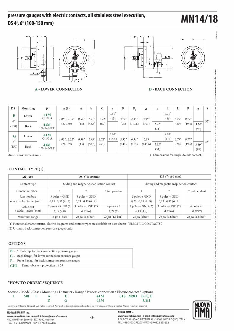
MN14/18
F SL peD1 dbA (1) c PDa C hF
1 12 2
RC3 -
05/1
4
E
G
41MG 1/2 A
43M1/2-14 NPT
41MG 1/2 A
43M1/2-14 NPT
CH1 -
B -
C -
E -
pressure gauges with electric contacts, all stainless steel execution,DS 4”, 6” (100-150 mm)
Removable key, protection IP 55
OPTIONS
“U”-clamp, for back connection pressure gauges
Back flange, for lower connection pressure gauges
Front flange, for back connection pressure gauges
dimensions : inches (mm) (1) dimensions for single/double contact;
DS Mounting
Lower
Back
Lower
Back
35°
35°
(20)
(20)
0.79”
0.79”
(90)
(89)
3.54”
3.50”
(31)
(31)
1.22”
1.22”
(110,6)
(161)
4.35”
6.34”
(101)
(149,6)
3.98”
5,89
(48,5)
(50,5)
1.91”
1.99”
(27...60)
(26...59)
1.06”...2.36”
1.02”...2.32”
(86)
(117)
3.39”
4.61”
(15)
(15,5)
0.59”
0.61”
(19,6)
(19,6)
0.77”
0.77”
(95)
(141)
3.74”
5.55”
(13)
(15)
0.51”
0.59”
(69)
(69)
2.72”
2.72”
(1) Functional characteristics, electric diagrams and contact types are available on data-sheets : “ELECTRIC CONTACTS”.
(2) U-clamp back connection pressure gauges only.
CONTACT TYPE (1)
Contact type
MODEL
Contact number
Minimum range
Sliding and magnetic snap-action contact
DS 6” (150 mm)
Sliding and magnetic snap-action contact
DS 4” (100 mm)
15 psi (1bar) 15 psi (1bar)23 psi (1,6 bar) 23 psi (1,6 bar)23 psi (1,6 bar) 23 psi (1,6 bar)
Junction box 3 poles + GND 3 poles + GND 3 poles + GND 3 poles + GND
ø exit cables: inches (mm) 0,23...0,35 (6...9) 0,23...0,35 (6...9) 0,23...0,35 (6...9) 0,23...0,35 (6...9)
2 indipendent 2 indipendent
Cable exit 4 poles + 1
ø cable: inches (mm) 0,27 (7)
3 poles + GND (2)
0,23 (6)
2 poles + GND (2)
0,19 (4,8)
4 poles + 1
0,27 (7)0,23 (6)0,19 (4,8)
3 poles + GND (2)2 poles + GND (2)
A - LOWER CONNECTION D - BACK CONNECTION
(100)
(150)
4”
6”
“HOW TO ORDER” SEQUENCE
Section / Model /Case / Mounting / Diameter / Range / Process connection / Electric contact / Options
1 M8 1 A E 41M 01S...M9D B, C, E D G 43M CH1
IN O
RD
ER
TO
IM
PR
OV
E T
HE
IR P
RO
DU
CT
ION
, ME
SSR
S. N
UO
VA
FIM
A R
ESE
RV
E T
HE
RIG
HT
TO
TH
EM
SELV
ES
TO
MA
KE
AL
L T
HE
MO
DIF
ICA
TIO
NS
TH
AT
TH
EY
DE
EM
IN
DIS
PE
NSA
BL
E A
T A
NY
TIM
E. U
PD
AT
ED
DA
TA
-SH
EE
TS
AR
E A
VA
ILA
BL
E O
N S
ITE
: ww
w.n
uo
vafi
ma.
com
Copyright © Nuova Fima srl. All rights reserved. Any part of this publication should not be reproduced without a written Nuova Fima’s srl approval

-1-ISO 9001 : 2008Cert. nr. 0433/6
MS1
◆◆◆◆◆◆◆◆◆◆◆
◆◆◆◆◆
◆◆◆◆◆◆◆◆
◆◆◆◆◆◆◆◆◆◆◆
◆◆◆◆◆◆◆◆◆◆◆
◆◆◆◆◆◆◆◆◆◆◆
◆◆◆◆◆◆
◆
◆◆◆◆◆◆
◆◆◆◆◆◆◆◆◆
◆◆
◆
◆◆◆◆◆◆
◆◆◆◆◆◆◆◆◆
◆◆
◆
◆ ◆
◆◆◆
◆◆◆
◆
◆◆◆
◆◆◆◆◆◆◆◆
◆◆◆
◆◆◆◆◆◆◆◆
MS2psibar
bar
AB
AB
AB
AB
AB
AB
AB
B
B
B
B
B
kPa
AB
AB
AB
AB
AB
AB
MPaAB
AB
AB
AB
B
B
B
B
B
bar kPa MPa(1)
psi int.psi bar kPa psi*
ABC
ABC
ABC
ABC
ABC
ABC
ABC
C
C
C ABC
ABC
ABC
ABC
ABC
ABC
ABC
ABC
ABC
C
standard version : DS 6” (150mm)
bourdon tube pressure gauges : available ranges
standard version : DS 1.5”, 2” (40-50mm)
standard version : DS 1.5”, 2”, 2.5” (40-50-63mm)
RANGESRANGES
bar ext.RANGES
kPa ext.
RANGES
* vacuum measurement unit : "inHg"
psi int.*
kPa ext.
RANGES
* vacuum measurement unit : "inHg"
bar ext.RANGES
RANGES
“A” = DS 1.5”(40mm); “B” = DS 2” (50mm).
(1) available also kg/cm2
0...10...1,60...2,50...40...6
0...100...160...250...400...60
0...1000...1600...2500...4000...600
0...10000...16000...2500
0...10...1,60...2,50...40...6
0...100...160...250...400...60
0...1000...1600...2500...4000...600
0...10000...16000...2500
0...150...300...60
0...1000...1600...2000...3000...4000...600
0...15000...20000...30000...40000...50000...6000
0...100000...15000
0...10000...800
-1...0,6-1...0
-1...1,5-1...3-1...5-1...9
-1...15-1...24
-100...0-100...150-100...300-100...500-100...900
-100...1500
-30...0-30...15-30...30
-30...150
0...1
0...1,6
0...2,5
0...4
0...6
0...10
0...16
0...25
0...40
-1...0 0...15
0...30
0...60
0...100
0...160
0...200
0...300
0...400
0...500
0...600
“A” = DS 1.5”(40mm); “B” = DS 2” (50mm); “C” = DS 2.5”(63mm).
psi int.psi int.*
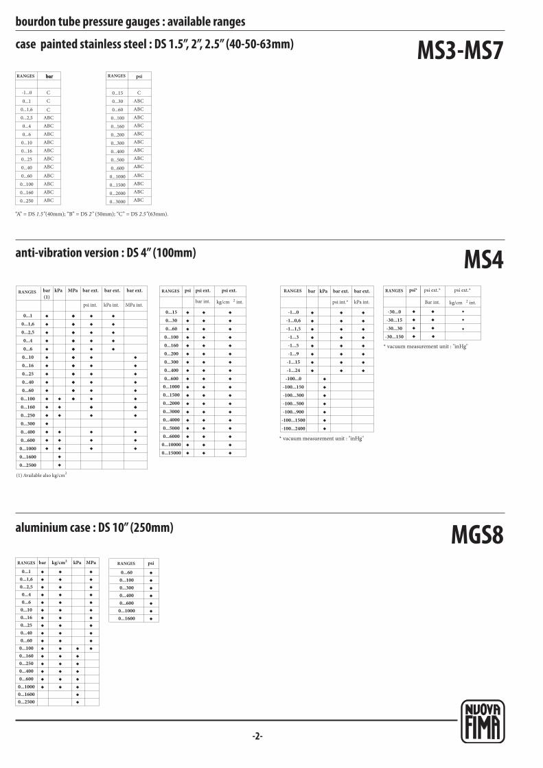
-2-
psibarbar
MS3-MS7
MGS8◆◆◆◆◆◆◆◆◆◆◆◆◆
◆◆◆◆◆◆◆◆◆◆◆◆◆
◆◆◆
◆◆
◆◆◆◆◆◆◆◆◆◆
◆◆
◆◆
◆◆
◆◆◆◆◆◆◆
bar kg/cm2 kPa MPa psi
◆ ◆ ◆
◆
MS4
(1)
◆◆◆◆◆◆◆◆◆◆◆
◆◆◆◆◆◆
◆◆◆
◆◆◆◆◆
◆◆◆◆◆◆◆◆◆◆◆
◆◆◆◆◆◆◆◆◆◆◆
◆◆◆◆◆◆◆◆◆◆◆
◆◆◆
◆◆◆
◆◆◆◆◆
◆◆◆◆◆◆◆◆◆
◆◆◆
◆◆◆◆◆
◆◆◆◆◆◆◆◆◆◆◆
◆
◆◆◆◆◆
◆◆◆◆◆◆◆◆◆◆◆
◆
◆◆◆◆◆
◆◆◆◆◆◆◆◆◆◆◆
◆◆ ◆ ◆
◆◆◆◆
◆◆◆◆◆◆◆◆
◆◆◆
◆◆◆◆◆◆◆◆
◆◆◆◆◆◆◆◆
◆◆◆◆
◆◆◆◆
◆
◆
◆
bar kPa psi*
2kg/cm2kg/cm
bar kPa MPa psi
ABC
ABC
ABC
ABC
ABC
ABC
ABC
ABC
ABC
ABC
ABC
C
C
C
ABC
ABC
ABC
ABC
ABC
ABC
ABC
ABC
ABC
ABC
ABC
ABC
ABC
C
bourdon tube pressure gauges : available ranges
case painted stainless steel : DS 1.5”, 2”, 2.5” (40-50-63mm)
RANGESRANGES
aluminium case : DS 10” (250mm)
RANGES RANGES
anti-vibration version : DS 4” (100mm)
bar ext. bar ext. bar ext.RANGES
(1) Available also kg/cm2
psi ext. psi ext.RANGES
* vacuum measurement unit : "inHg"
psi ext.* psi ext.*RANGES
* vacuum measurement unit : "inHg"
bar ext. bar ext.RANGES
0...10...1,60...2,50...40...6
0...100...160...250...400...60
0...1000...1600...2500...3000...4000...600
0...10000...1600
0...150...300...60
0...1000...1600...2000...3000...4000...600
0...15000...20000...30000...40000...50000...6000
0...100000...15000
0...1000
-1...0,6-1...1,5-1...3-1...5-1...9
-1...15-1...24
-100...0
-100...300-100...500-100...900
-100...1500-100...2400
-1...0 -30...0-30...15-30...30
-30...150
0...1,60...2,50...40...6
0...100...160...250...400...60
0...1000...1600...2500...400
0...16000...2500
0...6000...1000
0...1 0...600...1000...3000...4000...600
0...10000...1600
0...1
0...1,6
0...2,5
0...4
0...6
0...10
0...16
0...25
0...40
0...60
0...100
0...160
0...250
-1...0 0...15
0...30
0...60
0...100
0...160
0...200
0...300
0...400
0...500
0...600
0...1000
0...1500
0...2000
0...3000
0...2500
-100...150
“A” = DS 1.5”(40mm); “B” = DS 2” (50mm); “C” = DS 2.5”(63mm).
psi int. kPa int. MPa int.bar int. int. psi int.* kPa int. Bar int. int.

-3-
MGS44
◆◆◆◆◆◆◆◆◆◆◆◆
◆◆◆◆◆◆
◆◆◆◆◆◆◆
◆◆◆◆◆◆◆◆◆◆◆◆
MGS10bar kPa MPa
◆◆◆◆◆◆◆◆◆
◆◆◆◆
◆◆◆
◆◆◆◆◆
◆◆◆◆◆◆◆◆◆
◆◆◆◆◆◆◆◆◆◆◆
◆◆◆◆◆◆◆◆◆◆◆
◆◆◆
◆
◆◆◆
◆◆◆◆◆◆◆◆◆◆◆◆
bar kPa MPa psi
bourdon tube pressure gauges : available ranges
anti-vibrations version : DS 2” (50mm)
bar ext.RANGES
stainless steel bourdon tube : DS 4” (100mm)
0...2,50...40...6
0...100...160...250...400...60
0...1000...1600...2500...4000...600
0...10000...16000...2500
bar ext.RANGES RANGES
0...10...1,60...2,50...40...6
0...100...160...250...400...60
0...1000...1600...2500...3000...4000...600
0...10000...1600
0...150...300...60
0...1000...1600...2000...3000...4000...600
0...15000...20000...30000...40000...6000
0...1000
0...2500
psi int.
psi int.

-4-
MGS18◆◆◆◆◆◆◆
◆◆◆◆◆◆
◆◆
bar kPa MPa
◆◆◆◆◆◆◆◆◆◆◆◆◆◆◆◆
◆◆◆
◆◆◆◆◆
◆◆◆◆◆◆◆◆◆◆
◆◆◆◆◆◆◆◆◆◆◆◆◆◆◆◆
◆◆◆◆◆
◆◆◆◆◆◆◆◆
◆◆
◆◆◆◆◆◆◆◆◆◆◆◆◆◆◆◆◆◆
◆◆◆◆◆◆◆◆◆◆◆◆◆◆◆◆◆◆
◆◆◆◆◆◆◆◆◆◆◆◆◆◆◆◆◆◆
◆◆◆◆◆◆◆◆◆◆◆◆◆◆◆◆◆◆
◆◆◆◆◆◆◆◆
◆◆◆◆◆◆
◆◆◆◆◆◆◆◆
◆◆◆◆◆◆◆◆
◆◆◆◆
◆◆◆
◆◆◆◆
◆◆◆
kg/cm 2
bar kPa MPakg/cm
psi2
MGS10
◆◆
◆◆◆◆
◆◆
◆◆◆◆◆◆◆
◆◆◆
◆
◆◆◆◆◆◆
◆◆◆◆◆◆◆◆◆◆◆◆
◆
◆◆◆◆◆◆
◆◆◆◆◆◆◆◆◆◆◆◆
◆
◆◆◆◆◆◆
◆◆◆◆◆◆◆◆◆◆◆◆
◆
kg/cm2 kg/cm 2
◆◆◆◆◆◆◆◆◆◆◆
◆◆◆◆◆◆
◆◆◆
◆◆◆◆◆
◆◆◆◆◆◆◆◆◆◆◆
◆◆◆◆◆◆◆◆◆◆◆
◆◆◆◆◆◆◆◆◆◆◆
◆◆◆
◆◆◆
◆◆◆◆◆
◆◆◆◆◆◆◆◆◆
◆◆◆
bar kPa MPa psi
◆◆◆◆
◆◆◆◆◆◆◆◆
◆◆◆
◆◆◆◆◆◆◆◆
◆◆◆◆◆◆◆◆
bar kPa
◆◆◆◆
◆◆◆◆
◆◆◆
◆◆◆
psi*
MGS10
bourdon tube pressure gauges : available ranges
all stainless steel construction : DS 1.5”, 2” (40-50mm)
RANGES
anti-vibrations version : DS 2.5” (63mm)
bar ext. bar ext. bar ext.RANGES RANGES
* vacuum measurement unit: "inHg"
RANGES bar ext. bar ext.bar kPa
*psi int. kPa int.
* vacuum measurement unit: "inHg"
kPa ext.
* psi ext. * psi ext.RANGES * psikPa ext.
psi ext. psi ext.
anti-vibrations version : DS 4” (100mm)
bar ext. bar ext. bar ext.RANGES
kPa ext.
psi ext. psi ext.RANGES bar ext. bar ext.RANGES
kPa ext.
psi ext.* psi ext.*RANGES
* vacuum measurement unit: "inHg"
* vacuum measurement unit: "inHg"
0...1
0...1,6
0...2,5
0...4
0...6
0...10
0...16
0...25
0...40
0...60
0...100
0...160
0...250
0...300
0...400
0...600
0...1000
0...1600
0...2500
0...15
0...30
0...60
0...100
0...160
0...200
0...300
0...400
0...500
0...600
0...1000
0...1500
0...2000
0...3000
0...4000
0...5000
0...6000
0...10000
-1...0-1...0,6-1...1,5-1...3-1...5-1...9
-1...15-1...24
-100...0-100...150-100...300-100...500-100...900
-100...1500
-30...0
-30...15
-30...30
-30...150
0...10...1,60...2,50...40...6
0...100...160...250...400...60
0...1000...1600...2500...3000...4000...600
0...10000...16000...2500
0...150...300...60
0...100
0...1600...2000...3000...4000...600
0...800
0...15000...20000...30000...40000...50000...6000
0...100000...15000
0...1000
-1...0-1...0,6-1...1,5-1...3-1...5-1...9
-1...15-1...24
-100...0-100...150-100...300-100...500-100...900
-100...1500-100...2400
-30...0-30...15-30...30
-30...150
0...2,50...40...6
0...100...160...250...40
0...2500...4000...600
0...10000...16000...2500
int.psi int. kPa int. MPa int. int.
psi int.bar int.
* psi int.bar int.
int. int.psi int. kPa int. MPa int.
psi int.
bar int. psi int.* kPa int.
psi int.*
bar int.
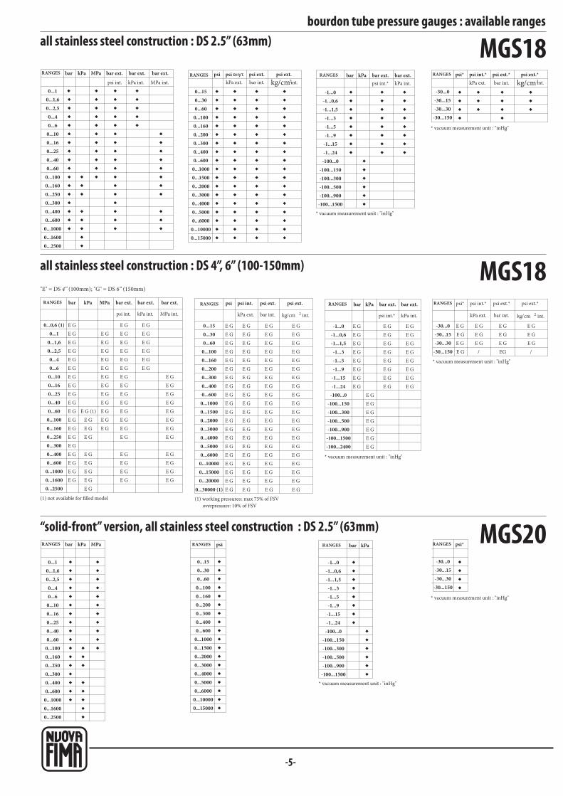
-5-
MGS18◆◆◆◆◆◆◆◆◆◆◆◆◆◆◆◆◆
◆◆◆
◆◆◆
◆◆◆◆◆◆◆◆◆◆◆
◆◆◆◆◆◆◆◆◆◆◆◆◆◆◆◆◆
◆◆◆◆◆
◆◆◆◆◆◆◆◆
◆◆◆
◆◆
◆◆◆◆◆◆◆◆◆◆◆◆◆◆◆◆◆◆
◆◆◆◆◆◆◆◆◆◆◆◆◆◆◆◆◆◆
◆◆◆◆◆◆◆◆◆◆◆◆◆◆◆◆◆◆
◆◆◆◆◆◆◆◆◆◆◆◆◆◆◆◆◆◆
◆◆◆◆◆◆◆◆
◆◆◆◆◆◆
◆◆◆◆◆◆◆◆
◆◆◆◆◆◆◆◆
◆◆◆◆
◆◆◆
◆◆◆◆
◆◆◆
bar kPa MPa psi psi внут.kg/cm2
bar kPa psi*kg/cm2
E G
E G
E G
E G
E G
E G
E G
E G
E G
E G
E G
E G
E G
E G
E G
E G
E G
E G
E G
E G (1)
E G
E G
E G
E G
E G
E G
E G
E G
E G
E G
E G
E G
E G
E G
E G
E G
E G
E G
E G
E G
E G
E G
E G
E G
E G
E G
E G
E G
E G
E G
E G
E G
E G
E G
E G
E G
E G
E G
E G
E G
E G
E G
E G
E G
E G
E G
E G
E G
E G
E G
E G
E G
E G
E G
E G
E G
E G
E G
E G
E G
E G
E G
E G
E G
E G
E G
E G
E G
E G
E G
E G
E G
E G
E G
E G
E G
E G
E G
E G
E G
E G
E G
E G
E G
E G
E G
E G
E G
E G
E G
E G
E G
E G
E G
E G
E G
E G
E G
E G
E G
E G
E G
E G
E G
E G
E G
E G
E G
E G
E G
E G
E G
E G
E G
E G
E G
E G
E G
E G
E G
E G
E G
E G
E G
E G
E G
E G
E G
E G
E G
E G
E G
E G
E G E G E G
E G
E G
E G
E G
E G
E G
E G
/
E G
E G
E G
EG
E G
E G
E G
/
E G
E G
E G
E G
E G
E G
E G
E G
E G
E G
E G
E G
E G
E G
E G
E G
E G
E G
E G
E G
E G
E G
E G
E G
E G
E G
E G
E G
E G
E G
E G
kg/cm 2kg/cm 2
MGS18
◆◆◆◆◆◆◆◆◆◆◆◆◆◆◆◆◆
◆◆◆
◆◆◆
◆◆◆◆◆◆◆◆◆◆◆
◆◆
◆◆◆◆◆◆◆◆◆◆◆◆◆◆◆◆◆◆
◆◆◆◆◆◆◆◆
◆◆◆◆◆◆
◆◆◆◆
bar kPa MPa psi bar kPa psi*
MGS20
bar kPa MPa psi bar kPa psi*
bourdon tube pressure gauges : available rangesall stainless steel construction : DS 2.5” (63mm)
bar ext. bar ext. bar ext.RANGES
kPa ext.
psi ext. psi ext.RANGES
* vacuum measurement unit : "inHg"
bar ext. bar ext.RANGES
* vacuum measurement unit : "inHg"
kPa ext.
psi ext.* psi ext.*RANGES
all stainless steel construction : DS 4”, 6” (100-150mm)
(1) not available for filled model
bar ext. bar ext. bar ext.RANGES
kPa ext.
psi ext. psi ext.RANGES
(1) working pressureo: max 75% of FSV
overpressure: 10% of FSV
kPa ext.
psi ext.* psi ext.*RANGES
* vacuum measurement unit : "inHg"
* vacuum measurement unit : "inHg"
bar ext. bar ext.RANGES
“solid-front” version, all stainless steel construction : DS 2.5” (63mm)
RANGES RANGES
* vacuum measurement unit : "inHg"
RANGES
* vacuum measurement unit : "inHg"
RANGES
0...150...300...60
0...1000...1600...2000...3000...4000...600
0...10000...15000...20000...30000...40000...50000...6000
0...100000...15000
0...10...1,60...2,50...40...6
0...100...160...250...400...60
0...1000...1600...2500...3000...4000...600
0...10000...16000...2500
-1...0-1...0,6-1...1,5-1...3-1...5-1...9
-1...15-1...24
-100...0-100...150-100...300-100...500-100...900
-100...1500
-30...0-30...15-30...30
-30...150
0...0,6 (1)0...1
0...1,60...2,50...40...6
0...100...160...250...400...60
0...1000...1600...2500...3000...4000...600
0...10000...16000...2500 0...30000 (1)
0...150...300...60
0...1000...1600...2000...3000...4000...600
0...10000...15000...20000...30000...40000...50000...6000
0...100000...150000...20000
-30...15-30...30
-30...150
-30...0
0...10...1,60...2,50...40...6
0...100...160...250...400...60
0...1000...1600...2500...3000...4000...600
0...10000...16000...2500
0...150...300...60
0...1000...1600...2000...3000...4000...600
0...10000...15000...20000...30000...40000...50000...6000
0...100000...15000
-1...0-1...0,6-1...1,5-1...3-1...5-1...9
-1...15-1...24
-100...0-100...150-100...300-100...500-100...900
-100...1500
-30...0-30...15-30...30
-30...150
psi int. kPa int. MPa int. bar int. int. psi int.* kPa int.
psi int.*bar int. int.
psi int. kPa int. MPa int.
psi int.
bar int. int. psi int.* kPa int.
psi int.*
bar int. int.
-1...0-1...0,6-1...1,5-1...3-1...5-1...9
-1...15-1...24
-100...0-100...150-100...300-100...500-100...900
-100...1500-100...2400
"E" = DS 4” (100mm); "G" = DS 6” (150mm)
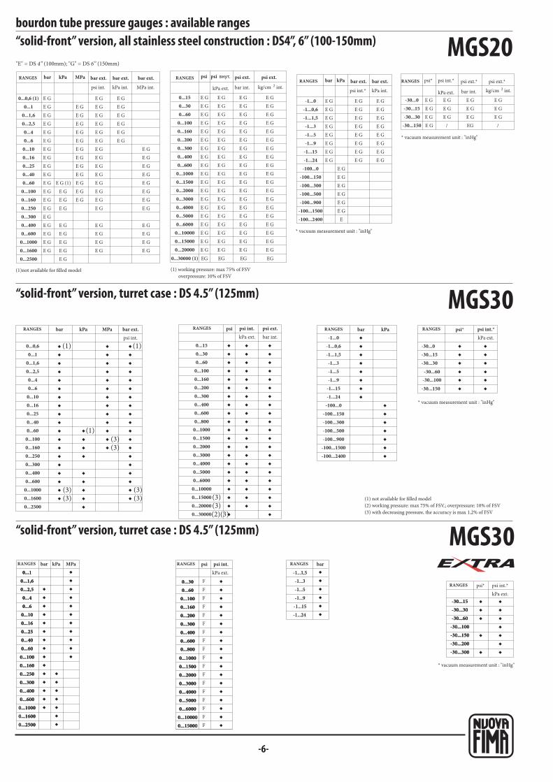
bar kPa MPa psi psi внут.
bar kPa MPa psi bar kPa psi*
psi
F
F
F
F
F
F
F
F
F
F
F
F
F
F
F
F
F
F
bar kPa MPa bar
psi*
-6-
MGS20
MGS30◆
◆◆◆◆◆◆◆◆◆◆◆◆◆◆◆◆ (3)
◆◆◆
◆◆◆◆◆
◆
◆◆◆◆◆◆◆◆◆◆ (3)
◆
◆◆◆◆◆◆◆◆◆◆◆◆◆◆◆◆ (3)
◆ ◆ ◆(1) (1)
(1)
◆ (3)
◆ (3)◆ (3)
◆
◆◆◆◆◆◆◆◆◆
◆◆◆◆◆◆◆◆◆
◆◆◆◆◆◆◆◆◆
◆◆◆◆◆◆◆◆◆
◆ ◆◆
◆ ◆
(2)(3)(3)(3)
◆◆◆◆◆◆◆◆◆
◆◆◆◆◆◆◆◆◆◆◆
◆
◆◆◆◆◆◆◆◆
◆◆◆◆◆◆◆
◆◆◆◆
◆◆◆◆
◆◆
◆◆
E G
E G
E G
E G
E G
E G
E G
E G
E G
E G
E G
E G
E G
E G
E G
E G
E G
E G
E G
E G (1)
E G
E G
E G
E G
E G
E G
E G
E G
E G
E G
E G
E G
E G
E G
E G
E G
E G
E G
E G
E G
E G
E G
E G
E G
E G
E G
E G
E G
E G
E G
E G
E G
E G
E G
E G
E G
E G
E G
E G
E G
E G
E G
E G
E G
E G
E G
E G
E G
E G
E G
E G
E G
E G
E G
E G
E G
E G
E G
E G
E G
E G
E G
E G
E G
E G
E G
E G
E G
E G
E G
E G
E G
E G
E G
E G
E G
E G
E G
E G
E G
E G
E G
E G
E G
E G
E G
E G
E G
E G
E G
E G
E G
E G
E G
E G
E G
E G
E G
E G
E G
E G
E G
E G
E G
E G
E G
E G
E G
E G
E G
E G
E G
E G
E G
E G
E G
E G
E G
E G
E G
E G
E G
E G
E G
E G
E G
E G
E G
E G
E G
E G
E G
EG EG EG EG
E G
E G
E G
E G
E G
E G
E G
/
E G
E G
E G
EG
E G
E G
E G
/
E G
E G
E G
E G
E G
E G
E G
E G
E G
E G
E G
E G
E G
E G
E
E G
E G
E G
E G
E G
E G
E G
E G
E G
E G
E G
E G
E G
E G
E G
E G
kg/cm 2
psi*
kg/cm 2
bar kPa
MGS30
◆◆◆◆◆◆◆◆◆◆◆◆◆◆◆
◆◆◆◆◆◆◆
◆◆◆◆◆◆◆◆◆◆◆
◆◆◆◆◆◆◆◆
◆◆◆◆◆◆◆◆◆
◆
◆◆◆◆◆◆
◆◆◆
◆
◆
◆◆◆◆◆◆◆
bourdon tube pressure gauges : available ranges“solid-front” version, all stainless steel construction : DS4”, 6” (100-150mm)
“solid-front” version, turret case : DS 4.5” (125mm)
(1) not available for filled model
(2) working pressure: max 75% of FSV.; overpressure: 10% of FSV
(3) with decreasing pressure, the accuracy is max 1,2% of FSV
psi int.
RANGES bar ext.kPa ext.
psi ext.RANGES RANGES
* vacuum measurement unit : "inHg"
kPa ext.
RANGES
(1)not available for filled model
bar ext. bar ext. bar ext.RANGES
kPa ext.
psi ext. psi ext.RANGES
(1) working pressure: max 75% of FSV
overpressure: 10% of FSV
kPa ext.
psi ext.* psi ext.*RANGES
* vacuum measurement unit : "inHg"
* vacuum measurement unit : "inHg"
bar ext. bar ext.RANGES
“solid-front” version, turret case : DS 4.5” (125mm)
RANGES RANGES RANGES
RANGES
* vacuum measurement unit : "inHg"
kPa ext.
kPa ext.
0...0,6 (1)0...1
0...1,60...2,50...40...6
0...100...160...250...400...60
0...1000...1600...2500...3000...4000...600
0...10000...16000...2500
0...150...300...60
0...1000...1600...2000...3000...4000...600
0...10000...15000...20000...30000...40000...50000...6000
0...100000...150000...20000
0...30000 (1)
-1...0-1...0,6-1...1,5-1...3-1...5-1...9
-1...15-1...24
-100...0-100...150-100...300-100...500-100...900
-100...1500-100...2400
-30...0-30...15-30...30
-30...150
0...0,6
0...1,60...2,50...40...6
0...100...160...250...400...60
0...1000...1600...2500...3000...4000...600
0...10000...16000...2500
0...1
0...150...300...60
0...1000...1600...2000...3000...4000...600
0...10000...15000...20000...30000...40000...50000...6000
0...100000...150000...200000...30000
0...800
-1...0-1...0,6-1...1,5-1...3-1...5-1...9
-1...15-1...24
-100...0-100...150-100...300-100...500-100...900
-100...1500-100...2400
-30...0-30...15-30...30
-30...60-30...100
-30...150
0...10...1,60...2,50...40...6
0...100...160...250...400...60
0...1000...1600...2500...3000...4000...600
0...10000...16000...2500
0...300...60
0...1000...1600...2000...3000...4000...600
0...10000...15000...20000...30000...40000...50000...6000
0...100000...15000
0...800
-1...1,5
-1...3
-1...5
-1...9
-1...15
-1...24
-30...15-30...30-30...60
-30...100-30...150-30...200-30...300
0...300...60
0...1000...1600...2000...3000...4000...600
0...10000...15000...20000...30000...40000...50000...6000
0...100000...15000
0...800
0...10...1,60...2,50...40...6
0...100...160...250...400...60
0...1000...1600...2500...3000...4000...600
0...10000...16000...2500
-1...1,5
-1...3
-1...5
-1...9
-1...15
-1...24
-30...15-30...30-30...60
-30...100-30...150-30...200-30...300
psi int. kPa int. MPa int. bar int. int.
psi int.*
bar int. int.psi int.* kPa int.
psi int.bar int.
psi int.*
psi int.
psi int.*
"E" = DS 4” (100mm); "G" = DS 6” (150mm)
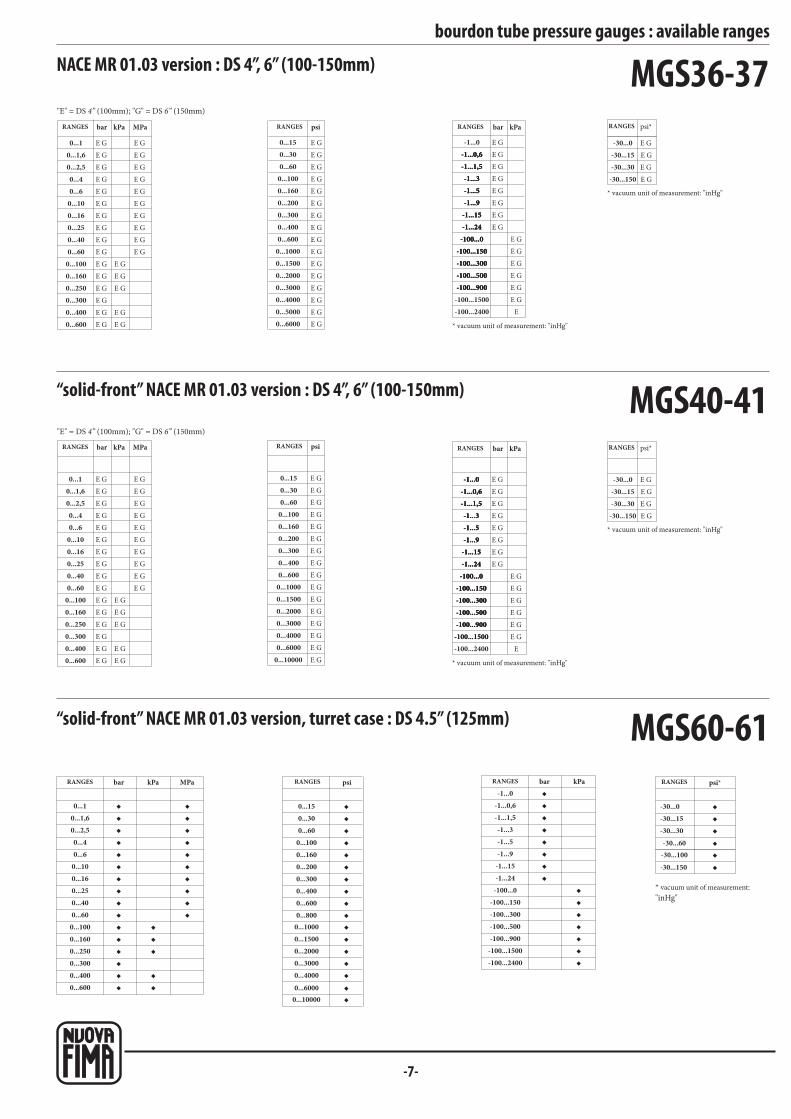
bar kPa MPa psi bar kPa psi*
psi
-7-
◆◆◆◆◆◆◆◆◆◆◆◆◆◆◆
◆◆◆
◆◆
◆◆◆◆◆◆◆◆◆
◆ ◆ ◆◆◆◆◆◆◆◆◆
◆◆◆◆◆◆
◆
◆
◆◆◆◆◆◆◆◆
◆◆◆◆◆◆◆
◆◆◆◆◆◆
MGS60-61
MGS40-41
MGS36-37
E G
E G
E G
E G
E G
E G
E G
E G
E G
E G
E G
E G
E G
E G
E G
E G
E G
E G
E G
E G
E G
E G
E G
E G
E G
E G
E G
E G
E G
E G
E G
E G
E G
E G
E G
E G
E G
E G
E G
E G
E G
E G
E G
E G
E G
E G
E G
E G
E G
E G
E G
E G
E G
E G
E G
E G
E G
E G
E G
E G
E G
E
E G
E G
E G
E G
E G
E G
E G
E G
E G
E G
E G
E G
E G
E G
E G
E G
E G
E G
E G
E G
E G
E G
E G
E G
E G
E G
E G
E G
E G
E G
E G
E G
E G
E G
E G
bar kPa MPa
E G
E G
E G
E G
E G
E G
E G
E G
E G
E G
E G
E G
E G
E G
E G
E G
E G
E G
E G
E G
E G
E G
E G
E G
E G
E G
E G
E G
E G
E G
E
bar kPa
E G
E G
E G
E G
psi*
bar kPa MPa psi bar kPa psi*
bourdon tube pressure gauges : available ranges
NACE MR 01.03 version : DS 4”, 6” (100-150mm)
“solid-front” NACE MR 01.03 version : DS 4”, 6” (100-150mm)
“solid-front” NACE MR 01.03 version, turret case : DS 4.5” (125mm)
RANGES RANGES RANGES
* vacuum unit of measurement:
"inHg"
RANGES
RANGES RANGES
* vacuum unit of measurement: "inHg"
RANGES RANGES
* vacuum unit of measurement: "inHg"
RANGES RANGES
* vacuum unit of measurement: "inHg"
RANGES RANGES
* vacuum unit of measurement: "inHg"
-1...0,6-1...1,5-1...3-1...5-1...9
-1...15-1...24
-100...0-100...150-100...300-100...500-100...900
-1...0,6-1...1,5-1...3-1...5-1...9
-1...15-1...24
-100...0-100...150-100...300-100...500-100...900
-1...0,6-1...1,5-1...3-1...5-1...9
-1...15-1...24
-100...0-100...150-100...300-100...500-100...900
-100...1500-100...2400
-1...00...10...1,60...2,50...40...6
0...100...160...250...400...60
0...1000...1600...2500...3000...4000...600
-30...0-30...15-30...30
-30...150
0...10...1,60...2,50...40...6
0...100...160...250...400...60
0...1000...1600...2500...3000...4000...600
0...150...300...60
0...1000...1600...2000...3000...4000...600
0...10000...15000...20000...30000...40000...6000
0...10000
-1...0-1...0,6-1...1,5-1...3-1...5-1...9
-1...15-1...24
-100...0-100...150-100...300-100...500-100...900
-1...0-1...0,6-1...1,5-1...3-1...5-1...9
-1...15-1...24
-100...0-100...150-100...300-100...500-100...900
-1...0-1...0,6-1...1,5-1...3-1...5-1...9
-1...15-1...24
-100...0-100...150-100...300-100...500-100...900
-100...1500-100...2400-100...1500
-30...0-30...15-30...30
-30...150
0...1,60...2,50...40...6
0...100...160...250...400...60
0...1000...1600...2500...3000...4000...600
0...1 0...150...300...60
0...1000...1600...2000...3000...4000...600
0...10000...15000...20000...30000...40000...6000
0...800
0...10000
-1...0-1...0,6-1...1,5-1...3-1...5-1...9
-1...15-1...24
-100...0-100...150-100...300-100...500-100...900
-100...1500-100...2400
-30...0-30...15-30...30-30...60
-30...100-30...150
0...150...300...60
0...1000...1600...2000...3000...4000...600
0...10000...15000...20000...30000...40000...50000...6000
"E" = DS 4” (100mm); "G" = DS 6” (150mm)
"E" = DS 4” (100mm); "G" = DS 6” (150mm)
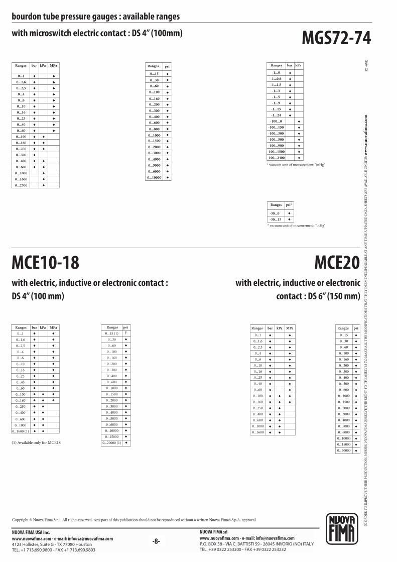
bar kPa MPa
F
psi bar kPa MPa psi
MGS72-74
MCE10-18
◆◆◆◆◆◆◆◆◆◆
◆◆◆◆◆
◆◆◆
◆◆◆◆◆
◆◆◆◆◆◆◆◆◆◆
◆◆◆◆◆◆◆◆◆◆◆
◆◆
◆◆◆◆
◆◆
◆◆◆◆◆◆◆
◆◆◆ ◆
◆◆◆
◆◆◆◆◆◆◆◆
◆◆◆
◆◆
MCE20
◆◆◆◆◆◆◆◆◆◆◆◆◆◆
◆◆◆
◆◆◆◆
◆◆◆
◆◆◆◆◆◆◆◆◆◆◆◆
◆◆◆◆◆◆◆◆◆◆◆◆◆◆◆◆◆◆
◆◆◆◆◆◆◆◆◆◆◆◆◆◆◆◆◆
◆◆◆◆◆◆◆
◆◆◆◆◆◆◆◆◆◆◆◆
◆◆◆◆◆◆◆◆◆◆◆◆◆◆◆◆◆◆◆◆
RC3 -
07/1
2
bourdon tube pressure gauges : available ranges
with microswitch electric contact : DS 4” (100mm)
with electric, inductive or electronic contact : DS 4” (100 mm)
Ranges bar kPa MPa Ranges psi
* vacuum unit of measurement: "inHg"
Ranges bar kPa
psi*Ranges
* vacuum unit of measurement: "inHg"
Ranges Ranges
with electric, inductive or electronic contact : DS 6” (150 mm)
(1) Available only for MCE18
Ranges Ranges
0...15
0...30
0...60
0...100
0...160
0...200
0...300
0...400
0...600
0...800
0...1500
0...2000
0...3000
0...4000
0...5000
0...6000
0...10000
0...1000
0...1
0...1,6
0...2,5
0...4
0...6
0...10
0...16
0...25
0...40
0...60
0...100
0...160
0...250
0...300
0...400
0...600
0...1000
0...1600
0...2500
-1...0
-1...0,6
-1...1,5
-1...3
-1...5
-1...9
-1...15
-1...24
-100...0
-100...150
-100...300
-100...500
-100...900
-100...1500
-100...2400
-30...0
-30...15
0...1
0...1,6
0...2,5
0...4
0...6
0...10
0...16
0...25
0...40
0...60
0...100
0...160
0...250
0...400
0...600
0...1000
0...1600 (1)
0...15 (1)
0...30
0...60
0...100
0...160
0...200
0...300
0...400
0...600
0...1000
0...1500
0...2000
0...3000
0...4000
0...5000
0...6000
0...10000
0...15000
0...20000 (1)
0...1
0...1,6
0...2,5
0...4
0...6
0...10
0...16
0...25
0...40
0...60
0...100
0...160
0...250
0...400
0...600
0...1000
0...1600
0...15
0...30
0...60
0...100
0...160
0...200
0...300
0...400
0...500
0...600
0...1000
0...1500
0...2000
0...3000
0...4000
0...5000
0...6000
0...10000
0...15000
0...20000
IN O
RD
ER
TO
IM
PR
OV
E T
HE
IR P
RO
DU
CT
ION
, ME
SSR
S. N
UO
VA
FIM
A R
ESE
RV
E T
HE
RIG
HT
TO
TH
EM
SELV
ES
TO
MA
KE
AL
L T
HE
MO
DIF
ICA
TIO
NS
TH
AT
TH
EY
DE
EM
IN
DIS
PE
NSA
BL
E A
T A
NY
TIM
E. U
PD
AT
ED
DA
TA
-SH
EE
TS
AR
E A
VA
ILA
BL
E O
N S
ITE
: ww
w.n
uo
vafi
ma.
com
Copyright © Nuova Fima S.r.l. All rights reserved. Any part of this publication should not be reproduced without a written Nuova Fima’s S.p.A. approval
-8-

-1-
MGS10
MGS18
MGS10-18-19-36
MGS20-21-40
MGS72-74
MCE10-18
MCE20
MGS18-19-36
MGS20-21-40
MN15
MN16-17
MN25
MS4-MGS44
MS1
b1
h1
E D f
MN14/10-18
MN14/10-18
MGS10
MGS18
MGS10
MGS18-19-36
MGS20-21-40
MGS72-74
MCE10-18
MGS18-19-36
MGS20-21-40
MN15
MN16-17
MN25
MGS20
D fa2
E
MS4 - MGS44
MN14/10-18
MN14/10-18
ISO 9001 : 2008Cert. nr. 0433/6
back flange lower connection pressure gaugesbourdon tube pressure gauges : mounting
(1) 1.32 (33,5) with crimped ring(2) 0.61 (15,5) with crimped ring
dimensions : inches (mm)
Model
2.85 (72,5)
3.01...3.41 (76,5...86,5)
1.48 (37,5) (1)
2.07 (52,5)
2.13 (54)
2.97 (75,5)
-
2.07 (52,5)
2.13 (54)
5.49 (139,5)
2.97 (75,5)
1.34 (34)
1.49 (38)
2.13 (54)
-
2.05 (52)
1.36 (34,5)
2.05 (52)
3.35 (85)
3.35 (85)
3.35 (85)
2.05 (52)
3.35 (85)
3.35 (85)
3.35 (85)
1.36 (34,5)
2.05 (52)
3.35 (85)
4.57...4.72 (116...120)
4.57...4.72 (116...120)
2.95 (75)
4.57...4.72 (116...120)
6.61...7.01 (168...178)
6.61...7.01 (168...178)
6.61...7.01 (168...178)
4.57...4.72 (116...120)
6.61...7.01 (168...178)
6.61...7.01 (168...178)
6.61...7.01 (168...178)
2.95 (75)
4.57...4.72 (116...120)
6.61...7.01 (168...178)
5.20 (132)
5.12 (130)
3.35 (85)
5.12 (130)
7.48 (190)
7.48 (190)
7.48 (190)
5.12 (130)
7.48 (190)
7.48 (190)
7.48 (190)
3.35 (85)
5.12 (130)
7.48 (190)
DS
2.5 (63)
4 (100)
4 (100)
4 (100)
4 (100)
6 (150)
6 (150)
6 (150)
6 (150)
6 (150)
6 (150)
2.5 (63)
4 (100)
6 (150)
0.24 (6)
0.24 (6)
0.14 (3,6)
0.24 (6)
0.24 (6)
0.24 (6)
0.24 (6)
0.24 (6)
0.24 (6)
0.24 (6)
0.24 (6)
0.14 (3,6)
0.24 (6)
0.24 (6)
2.07 (52,5) 2.05 (52) 4.57...4.72 (116...120) 5.12 (130)4 (100) 0.24 (6)
2.13 (54) 3.35 (85) 6.61...7.01 (168...178) 7.48 (190)6 (150) 0.24 (6)
dimensions : inches (mm)
Model DS
5.20 (132)
5.20 (132)
3.35 (85)
3.35 (85)
5.20 (132)
5.20 (132)
7.48 (190)
7.48 (190)
5.20 (132)
7.48 (190)
7.48 (190)
3.35 (85)
0.24 (6)
0.24 (6)
0.14 (3,6)
0.14 (3,6)
0.24 (6)
0.24 (6)
0.24 (6)
0.24 (6)
0.24 (6)
0.24 (6)
0.24 (6)
0.14 (3,6)
0.79 (20)
0.79 (20)
0.26 (6,6)
0.26 (6,6)
0.79 (20)
0.79 (20)
1 (25,5)
1 (25,5)
0.79 (20)
1 (25,5)
1 (25,5)
0.45 (11,5)
4.57...4.72 (116...120)
4.57...4.72 (116...120)
2.95 (75)
2.95 (75)
4.57...4.72 (116...120)
4.57...4.72 (116...120)
6.61...7.01 (168...178)
6.61...7.01 (168...178)
4.57...4.72 (116...120)
6.61...7.01 (168...178)
6.61...7.01 (168...178)
2.95 (75)
2.5 (63)
2.5 (63)
4 (100)
4 (100)
4 (100)
4 (100)
4 (100)
6 (150)
6 (150)
6 (150)
6 (150)
2.5 (63)
5.20 (132) 0.24 (6)0.71 (18) 4.57...4.72 (116...120)4 (100)
7.48 (190) 0.24 (6)1 (25,5) 6.61...7.01 (168...178)6 (150)
5.20 (132) 0.24 (6)0.79 (20) 4.57...4.72 (116...120)4 (100)
5.20 (132) 0.24 (6)0.79 (20) 4.57...4.72 (116...120)4 (100)
front flange back connection pressure gauges
E - FRONT FLANGE,
for back connection
C - BACK FLANGE,
for lower connection

RC2 -
07/1
5
MGS10-18-19-36
MN14/10-18
MGS18-19-36
MN15
MS1
a1
T Z VQ
MS4
MGS72-74
MN14/10-18
MS1, MGS10-18
VQ Z
MGS20-21-40
MGS20-21-40
b1
f D Eh1
MGS10-18
Z VQ
-2-
back flange lower connection for solid-front pressure gaugesbourdon tube pressure gauges : mounting
B - “U” CLAMP,
for back connection
C - BACK FLANGE,
for lower connection
dimensions : inches (mm)
0.79 (20)
0.79 (20)
0.81 (20,5)
0.81 (20,5)
1.63 (41,5)
1.63 (41,5)
1.63 (41,5)
1.63 (41,5)
4.41 (112)
4.41 (112)
6.10 (155)
6.10 (155)
4.41 (112)
4.41 (112)
6.46 (164)
6.46 (164)
0.81 (20,5) 1.63 (41,5) 6.10 (155)6.46 (164)
4 (100)
4 (100)
6 (150)
6 (150)
6 (150)
DSModel
--- 1.2 (30,5) 4.41 (112)---4 (100)
0.79 (20) 1.63 (41,5) 4.41 (112)4.41 (112)4 (100)
0.81 (20,5) 1.63 (41,5) 6.10 (155)6.46 (164)6 (150)
2.76 (70)
2.76 (70)
4.17 (106)
4.17 (106)
4.17 (106)
2.76 (70)
2.76 (70)
4.17 (106)
dimensions : inches (mm)
DS
2 (50)
Model
2.30 (58,5)2.46 (62,6) 2.66 (67,5)
clamp back connection pressure gauges
Model D S
4 (100)
6 (150)
2.85 (72,5)
2.85 (72,5)
0.24 (6)
0.24 (6)
5.19 (132)
7.48 (190)
4.56...4.72 (116...120)
6.61...7.00 (168...178)
-
3.34 (85)
dimensions : inches (mm)
DS
2.5 (63)
Model
3.54 (90) 2.83 (72)1.50 (38)
IN O
RD
ER
TO
IM
PR
OV
E T
HE
IR P
RO
DU
CT
ION
, ME
SSR
S. N
UO
VA
FIM
A R
ESE
RV
E T
HE
RIG
HT
TO
TH
EM
SELV
ES
TO
MA
KE
AL
L T
HE
MO
DIF
ICA
TIO
NS
TH
AT
TH
EY
DE
EM
IN
DIS
PE
NSA
BL
E A
T A
NY
TIM
E. U
PD
AT
ED
DA
TA
-SH
EE
TS
AR
E A
VA
ILA
BL
E O
N S
ITE
: ww
w.n
uo
vafi
ma.
com
NUOVA FIMA S.p.A. - www.nuovafima.comP.O. BOX 58 - VIA C. BATTISTI 59 - 28045 INVORIO (NO) ITALYTEL. +39 0322 253200 - FAX +39 0322 253232
Copyright © Nuova Fima srl. All rights reserved. Any part of this publication should not be reproduced without a written Nuova Fima’s srl approval
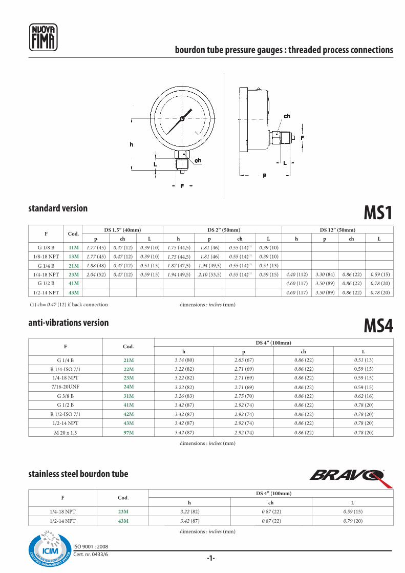
1/4-18 NPT
1/2-14 NPT
F
®
MS1
G 1/4 B
1/4-18 NPT
G 1/2 B
1/2-14 NPT
F
G 1/8 B
1/8-18 NPT
MS4
R 1/2-ISO 7/1
G 3/8 B
G 1/4 B
1/4-18 NPT
G 1/2 B
M 20 x 1,5
1/2-14 NPT
F
Cod.
21M
23M
41M
43M
11M
13M
42M
31M
21M
23M
41M
97M
43M
Cod.h p ch L
23M
43M
Cod.
p ch h p ch L h p ch LL
R 1/4-ISO 7/1 22M
7/16-20UNF 24M
h ch L
-1-ISO 9001 : 2008Cert. nr. 0433/6
bourdon tube pressure gauges : threaded process connections
stainless steel bourdon tube
DS 4” (100mm)
standard version
DS 12” (50mm)DS 2” (50mm)DS 1.5” (40mm)
(1) ch= 0.47 (12) if back connection
anti-vibrations version
DS 4” (100mm)
dimensions : inches (mm)
dimensions : inches (mm)
dimensions : inches (mm)
3.14 (80)
3.22 (82)
3.26 (83)
3.42 (87)
3.42 (87)
3.42 (87)
3.42 (87)
2.63 (67)
2.71 (69)
2.75 (70)
2.92 (74)
2.92 (74)
2.92 (74)
2.92 (74)
0.86 (22)
0.86 (22)
0.86 (22)
0.86 (22)
0.86 (22)
0.86 (22)
0.86 (22)
0.51 (13)
0.59 (15)
0.62 (16)
0.78 (20)
0.78 (20)
0.78 (20)
0.78 (20)
1.77 (45)
1.77 (45)
1.88 (48)
2.04 (52)
0.47 (12)
0.47 (12)
0.47 (12)
0.47 (12)
1.87 (47,5)
1.94 (49,5)
1.81 (46)
1.81 (46)
1.94 (49,5)
2.10 (53,5)
0.55 (14)(1)
0.55 (14)(1)
0.55 (14)(1)
0.55 (14)(1)
0.39 (10)
0.39 (10)
0.51 (13)
0.59 (15)
4.60 (117)
4.60 (117)
3.50 (89)
3.50 (89)
0.86 (22)
0.86 (22)
0.78 (20)
0.78 (20)
0.39 (10)
0.39 (10)
0.51 (13)
0.59 (15)
1.75 (44,5)
1.75 (44,5)
4.40 (112) 3.30 (84) 0.86 (22) 0.59 (15)
3.22 (82) 2.71 (69) 0.86 (22) 0.59 (15)
3.22 (82) 2.71 (69) 0.86 (22) 0.59 (15)
3.22 (82)
3.42 (87)
0.87 (22)
0.87 (22)
0.59 (15)
0.79 (20)

-2-
MGS18p ch L h p ch L h p ch L h p ch L h p ch L
R 1/2-ISO 7/1
G 3/8 B
G 1/4 B
1/4-18 NPT
3/8-18 NPT
G 1/2 B
M 20 x 1,5
1/2-14 NPT
F
G 1/8 B
1/8-18 NPT
R1/4-ISO7/1
MGS10
G 3/8 B
M10X1
G 1/4 B
1/4-18 NPT
R1/4-ISO7/1
7/16-20UNF
1/2-14 NPT
G 1/2 B
F
G 1/8 B
1/8-18 NPT
M20X1,5
31M
86M
21M
23M
22M
24M
43M
41M
Cod.
11M
13M
97M
h p ch L h p ch L h p ch L
42M
31M
21M
23M
33M
41M
97M
43M
Cod.
11M
13M
22M
bourdon tube pressure gauges : threaded process connections
all stainless steel version
DS 4” (100mm) DS 6” (150mm)DS 2.5” (63mm)DS 2” (50mm)DS 1.5” (40mm)
(1) ch= 0.47 (12) if back connection
(44)
(49)
(51)
(44)
1.73
1.92
2
1.73
(12)
(12)
(12)
(12)
0.47
0.47
0.47
0.47
(10)
(13)
(15)
(10)
0.39
0.51
0.59
0.39
(44,5)
(47,5)
(49,5)
(44,5)
1.75
1.87
1.94
1.75
(46)
(51)
(53)
(46)
1.81
2
2.08
1.81
(14)(1)
(14)(1)
(14)(1)
(14)(1)
0.55(1)
0.55(1)
0.55(1)
0.55(1)
(10)
(13)
(15)
(10)
0.39
0.51
0.59
0.39
(53)
(55)
(54)
(54)
(53)
2.08
2.16
2.12
2.12
2.08
(53)
(55)
(54)
(54)
(53)
2.08
2.16
2.12
2.12
2.08
(14)
(14)
(14)
(14)
(14)
0.55
0.55
0.55
0.55
0.55
(10)
(13)
(13)
(13)
(10)
0.39
0.51
0.51
0.51
0.39
(79)
(81)
(86)
(86)
(86)
(86)
(86)
(86)
3.11
3.18
3.38
3.38
3.38
3.38
3.38
3.38
(13)
(15)
(16)
(20)
(16)
(20)
(20)
(20)
0.51
0.59
0.62
0.78
0.62
0.78
0.78
0.78
(85)
(87)
(87)
(87)
(87)
(87)
(87)
(87)
3.34
3.42
3.42
3.42
3.42
3.42
3.42
3.42
(22)
(22)
(22)
(22)
(22)
(22)
(22)
(22)
0.86
0.86
0.86
0.86
0.86
0.86
0.86
0.86
(13)
(15)
(16)
(20)
(20)
(20)
(16)
(20)
0.51
0.59
0.62
0.78
0.78
0.78
0.62
0.78
(110)
(112)
(113)
(117)
(117)
(117)
(113)
(117)
4.33
4.40
4.44
4.6
4.6
4.6
4.44
4.6
(83,5)
(85,5)
(85,5)
(85,5)
(85,5)
(85,5)
(85,5)
(85,5)
3.28
3.36
3.36
3.36
3.36
3.36
3.36
3.36
(22)
(22)
(22)
(22)
(22)
(22)
(22)
(22)
0.86
0.86
0.86
0.86
0.86
0.86
0.86
0.86
anti-vibrations version
DS 4” (100mm)DS 2.5” (63mm)DS 2” (50mm)
dimensions : inches (mm)
dimensions : inches (mm)
(47,5)
(49,5)
1.87
1.94
(46)
(46)
1.81
1.81(14)(1)
(14)(1)
(14)(1)
(14)(1)
0.55
0.55
0.55
0.55
(10)
(10)
(13)
(15)
0.39
0.39
0.51
0.59
(53)
(53)
(55)
(54)
(53)
(54)
(56)
2.08
2.08
2.16
2.12
2.08
2.12
2.20
(53)
(53)
(55)
(54)
(53)
(54)
(56)
2.08
2.08
2.16
2.12
2.08
2.12
2.20
(14)
(14)
(14)
(14)
(14)
(14)
(14)
0.55
0.55
0.55
0.55
0.55
0.55
0.55
(10)
(10)
(13)
(13)
(10)
(13)
(14)
0.39
0.39
0.51
0.51
0.39
0.51
0.55
(81)
(83)
(83)
(84)
(83)
(88)
(88)
(88)
3.18
3.26
3.26
3.30
3.26
3.46
3.46
3.46
(83)
(85)
(85)
(86)
(85)
(90)
(90)
(90)
3.26
3.34
3.34
3.38
3.34
3.54
3.54
3.54
(22)
(22)
(22)
(22)
(22)
(22)
(22)
(22)
(22)
0.86
0.86
0.86
0.86
0.86
0.86
0.86
0.86
0.86
(13)
(15)
(15)
(16)
(15)
(20)
(20)
(20)
0.51
0.59
0.59
0.62
0.59
0.78
0.78
0.78
1.75(44,5)
1.75
(44,5)
1.94
(49,5)
2.10
(53,5)
(1) ch= 0.47 (12) if back connection

-3-
MGS19
R 1/2-ISO 7/1
G 3/8 B
G 1/4 B
1/4-18 NPT
3/8-18 NPT
G 1/2 B
M 20 x 1,5
1/2-14 NPT
F
MGS20
G 1/2 B
1/2-14 NPT
F
G 1/8 B
1/8-18 NPT
R 1/2-ISO 7/1
G 3/8 B
G 1/4 B
1/4-18 NPT
3/8-18 NPT
M 20 x 1,5
41M
23M
Cod.
11M
13M
42M
31M
21M
23M
33M
97M
h p ch L h p ch(1)
L h p ch(1)
L
42M
31M
21M
23M
33M
41M
97M
43M
Cod.Lh p ch L h p ch
bourdon tube pressure gauges : threaded process connection
all stainless steel version, heavy work
DS 6” (150mm)DS 4” (100mm)
(1) ch= 0.67 (17) for back connection dimensions : inches (mm)
dimensions : inches (mm)
DN 6” (150mm)DN 4” (100mm)DN 2.5” (63mm)
(53)
(53)
(55)
(54)
2.08
2.08
2.16
2.12
(58)
(58)
(60)
(59)
2.28
2.28
2.36
2.32
(14)
(14)
(14)
(14)
0.55
0.55
0.55
0.55
(10)
(10)
(13)
(13)
0.39
0.39
0.51
0.51(79)
(81)
(86)
(86)
(86)
(86)
(86)
(86)
3.11
3.19
3.39
3.39
3.39
3.39
3.39
3.39
(93,5)
(95,5)
(95,5)
(95,5)
(95,5)
(95,5)
(95,5)
(95,5)
3.68
3.76
3.76
3.76
3.76
3.76
3.76
3.76
(22)
(22)
(22)
(22)
(22)
(22)
(22)
(22)
0.87
0.87
0.87
0.87
0.87
0.87
0.87
0.87
(13)
(15)
(16)
(20)
(16)
(20)
(20)
(20)
0.51
0.59
0.63
0.79
0.63
0.79
0.79
0.79
(110)
(112)
(113)
(117)
(113)
(117)
(117)
(117)
4.33
4.41
4.45
4.61
4.45
4.61
4.61
4.61
(94)
(96)
(96)
(96)
(96)
(96)
(96)
(96)
3.70
3.78
3.78
3.78
3.78
3.78
3.78
3.78
(22)
(22)
(22)
(22)
(22)
(22)
(22)
(22)
0.87
0.87
0.87
0.87
0.87
0.87
0.87
0.87
(13)
(15)
(16)
(20)
(16)
(20)
(20)
(20)
0.51
0.59
0.63
0.79
0.63
0.79
0.79
0.79
0.51 (13)
0.59 (15)
0.63 (16)
0.63 (16)
0.79 (20)
0.79 (20)
0.79 (20)
0.79 (20)
3.11 (79)
3.19 (81)
3.39 (86)
3.39 (86)
3.39 (86)
3.39 (86)
3.39 (86)
3.39 (86)
3.35 (85)
3.43 (87)
3.43 (87)
3.43 (87)
3.43 (87)
3.43 (87)
3.43 (87)
3.43 (87)
0.87 (22)
0.87 (22)
0.87 (22)
0.87 (22)
0.87 (22)
0.87 (22)
0.87 (22)
0.87 (22)
0.51 (13)
0.59 (15)
0.63 (16)
0.79 (20)
0.79 (20)
0.79 (20)
0.63 (16)
0.79 (20)
4.33 (110)
4.41 (112)
4.45 (113)
4.61 (117)
4.61 (117)
4.61 (117)
4.45 (113)
4.61 (117)
3.29 (83,5)
3.37 (85,5)
3.37 (85,5)
3.37 (85,5)
3.37 (85,5)
3.37 (85,5)
3.37 (85,5)
3.37 (85,5)
0.87 (22)
0.87 (22)
0.87 (22)
0.87 (22)
0.87 (22)
0.87 (22)
0.87 (22)
0.87 (22)

-4-
MGS21
MN17G 1/4 B
1/4-18 NPT
G 1/2 B
1/2-14 NPT
F
MN16-MN25G 1/4 B (1)
1/4-18 NPT (1)
G 1/2 B
1/2-14 NPT
F
MN15G 1/4 B
1/4-18 NPT
G 1/2 B
1/2-14 NPT
F
R 1/2-ISO 7/1
G 3/8 B
G 1/4 B
1/4-18 NPT
3/8-18 NPT
G 1/2 B
M 20 x 1,5
1/2-14 NPT
F
42M
31M
21M
23M
33M
41M
97M
43M
Cod.Lh p L h p ch(1)ch(1)
21M
23M
41M
43M
Cod.h p ch L
21M
23M
41M
43M
Cod.h p Lch
21M
23M
41M
43M
Cod.h p Lch
bourdon tube pressure gauges : threaded process connection
all stainless steel version,“solid-front” heavy work
test gauge, “solid-front”, accuracy 0,25%
DS 6” (150mm)
(1) ch= 0.67 (17) for back connection dimensions : inches (mm)
all stainless steel test gauge, “solid-front” accuracy 0,6...0,25%
DS 6” (150mm)
(1) only for bottom connection on MN25(2) ch= 0.67 (17) for back connection
dimensions : inches (mm)
all stainless steel test gauge, accuracy 0,6%
DS 6” (150mm)
dimensions : inches (mm)
DS 6” (150mm)DS 4” (100mm)
0.51 (13)
0.59 (15)
0.63 (16)
0.79 (20)
0.63 (16)
0.79 (20)
0.79 (20)
0.79 (20)
3.11 (79)
3.19 (81)
3.39 (86)
3.39 (86)
3.39 (86)
3.39 (86)
3.39 (86)
3.39 (86)
3.68 (93,5)
3.76 (95,5)
3.76 (95,5)
3.76 (95,5)
3.76 (95,5)
3.76 (95,5)
3.76 (95,5)
3.76 (95,5)
0.51 (13)
0.59 (15)
0.63 (16)
0.79 (20)
0.63 (16)
0.79 (20)
0.79 (20)
0.79 (20)
4.33 (110)
4.41 (112)
4.45 (113)
4.61 (117)
4.45 (113)
4.61 (117)
4.61 (117)
4.61 (117)
3.70 (94)
3.78 (96)
3.78 (96)
3.78 (96)
3.78 (96)
3.78 (96)
3.78 (96)
3.78 (96)
0.87 (22)
0.87 (22)
0.87 (22)
0.87 (22)
0.87 (22)
0.87 (22)
0.87 (22)
0.87 (22)
0.87 (22)
0.87 (22)
0.87 (22)
0.87 (22)
0.87 (22)
0.87 (22)
0.87 (22)
0.87 (22)
4.33 (110)
4.61 (117)
4.41 (112)
4.61 (117)
3.29 (83,5)
3.37 (85,5)
3.37 (85,5)
3.37 (85,5)
0.87 (22)
0.87 (22)
0.87 (22)
0.87 (22)
0.51 (13)
0.59 (15)
0.79 (20)
4.33 (110)
4.61 (117)
4.41 (112)
4.61 (117)
3.74 (95)
3.82 (97)
3.82 (97)
3.82 (97)
0.51 (13)
0.59 (15)
0.79 (20)
0.79 (20)
0.87 (22) (2)
0.87 (22) (2)
0.87 (22) (2)
0.87 (22) (2)
4.37 (111)
4.65 (118)
4.45 (113)
4.65 (118)
3.76 (95,5)
3.84 (97,5)
3.84 (97,5)
3.84 (97,5)
0.51 (13)
0.59 (15)
0.79 (20)
0.79 (20)
0.94 (24) (1)
0.94 (24) (1)
0.94 (24) (1)
0.94 (24) (1)
(1) ch= 0.66 (17) if back connection
0.79 (20)
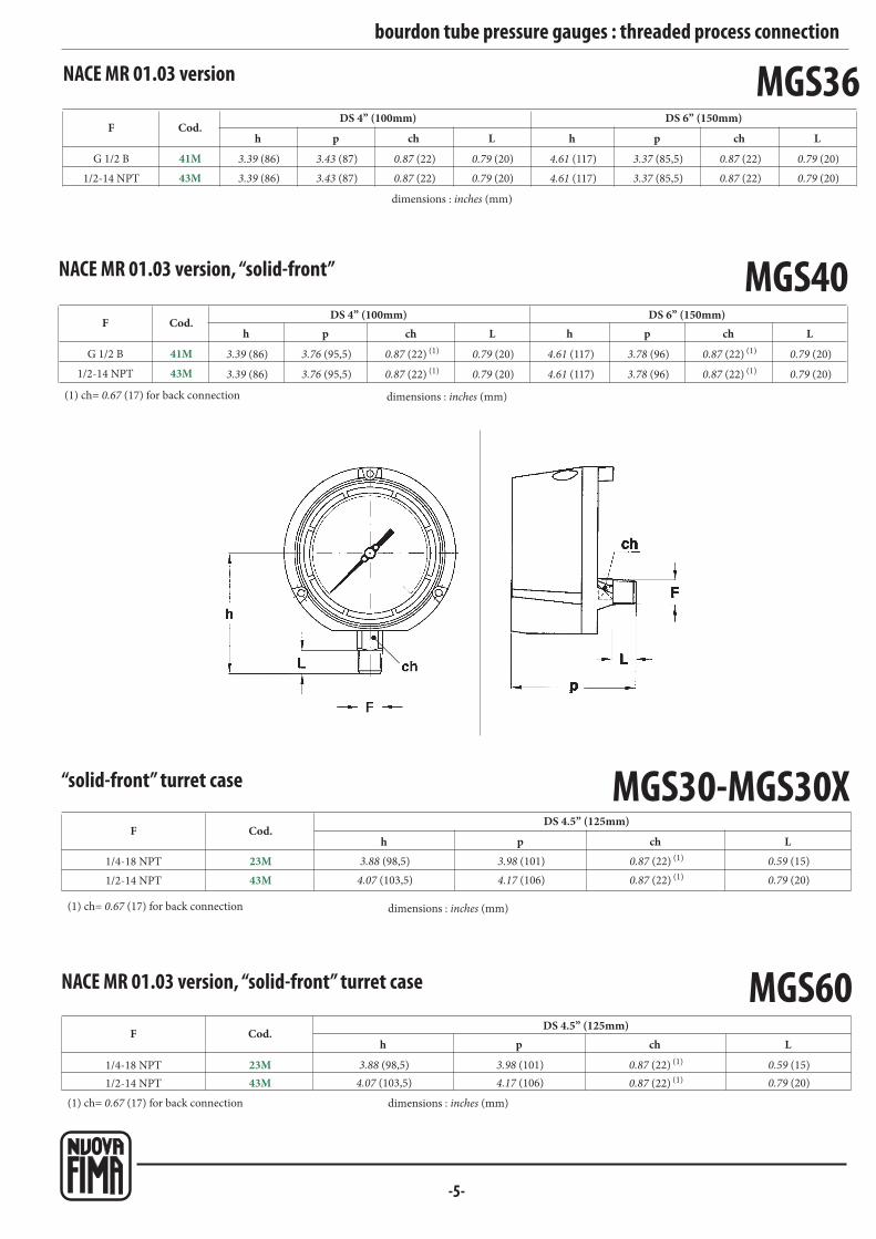
-5-
MGS36G 1/2 B
1/2-14 NPT
F
MGS40G 1/2 B
1/2-14 NPT
F
1/4-18 NPT
1/2-14 NPT
F
MGS60
MGS30-MGS30X1/4-18 NPT
1/2-14 NPT
F
41M
43M
Cod.h p h p ch LLch
41M
43M
Cod.h p h LchpLch
23M
43M
Cod.h p Lch
23M
43M
Cod.h p Lch
bourdon tube pressure gauges : threaded process connection
NACE MR 01.03 version
DS 6” (150mm)DS 4” (100mm)
dimensions : inches (mm)
(1) ch= 0.67 (17) for back connection
NACE MR 01.03 version, “solid-front”
DS 6” (150mm)DS 4” (100mm)
dimensions : inches (mm)
NACE MR 01.03 version, “solid-front” turret case
DS 4.5” (125mm)
(1) ch= 0.67 (17) for back connection dimensions : inches (mm)
“solid-front” turret case
DS 4.5” (125mm)
dimensions : inches (mm) (1) ch= 0.67 (17) for back connection
3.39 (86)
3.39 (86)
3.43 (87)
3.43 (87)
4.61 (117)
4.61 (117)
3.37 (85,5)
3.37 (85,5)
0.87 (22)
0.87 (22)
0.79 (20)
0.79 (20)
0.79 (20)
0.79 (20)
0.87 (22)
0.87 (22)
3.39 (86)
3.39 (86)
3.76 (95,5)
3.76 (95,5)
4.61 (117)
4.61 (117)
0.79 (20)
0.79 (20)
0.87 (22) (1)
0.87 (22) (1)
3.78 (96)
3.78 (96)
0.79 (20)
0.79 (20)
0.87 (22) (1)
0.87 (22) (1)
3.88 (98,5)
4.07 (103,5)
3.98 (101)
4.17 (106)
0.59 (15)
0.79 (20)
0.87 (22) (1)
0.87 (22) (1)
3.88 (98,5)
4.07 (103,5)
3.98 (101)
4.17 (106)
0.59 (15)
0.79 (20)
0.87 (22) (1)
0.87 (22) (1)
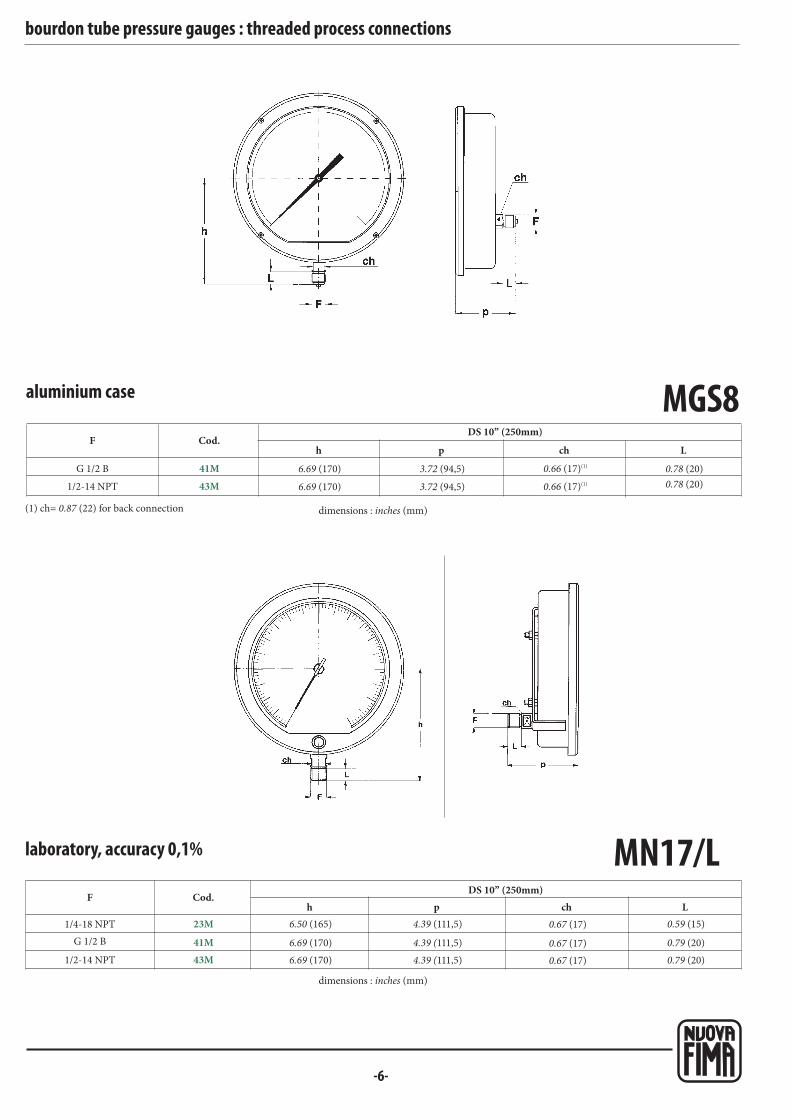
-6-
MN17/L
1/4-18 NPT
1/2-14 NPT
F
MGS8
G 1/2 B
1/2-14 NPT
F
41M
43M
Cod.h p Lch
23M
43M
Cod.h p Lch
41MG 1/2 B
bourdon tube pressure gauges : threaded process connections
DS 10” (250mm)
laboratory, accuracy 0,1%
aluminium case
DS 10” (250mm)
(1) ch= 0.87 (22) for back connection dimensions : inches (mm)
dimensions : inches (mm)
6.69 (170)
6.69 (170)
3.72 (94,5)
3.72 (94,5)
0.78 (20)
0.78 (20)
0.66 (17)(1)
0.66 (17)(1)
6.69 (170)
6.50 (165) 4.39 (111,5)
4.39 (111,5)
0.59 (15)
0.79 (20)
0.67 (17)
0.67 (17)
6.69 (170) 4.39 (111,5) 0.79 (20)0.67 (17)

-7-
MGS72-74G 1/4 B
1/4-18 NPT
G 3/8 B
3/8-18 NPT (1)
F
G 1/2 B
1/2-14 NPT
21M
23M
31M
33M
Cod.
41M
43M
h p Lch
MN14/10-18
G 1/4 B
1/4-18 NPT
G 1/2 B
1/2-14 NPT
F
R 1/2-ISO 7/1
M 20 x 1,5
21M
23M
41M
43M
Cod.
42M
97M
(1) MN14/10; (2) MN14/18
Lh(1) p(1) L h(1) p(1) chchh(2) p(2) h(2) p(2)
bourdon tube pressure gauges : threaded process connection
with microswitch
DS 4” (100mm)
dimensions : inches (mm)
3.18 (81)
3.30 (84)
3.26 (83)
3.30 (84)
3.46 (88)
3.46 (88)
3.27 (83)
3.35 (85)
3.39 (86)
3.39 (86)
3.54 (90)
3.54 (90)
0.51 (13)
0.59 (15)
0.63 (16)
0.63 (16)
0.79 (20)
0.79 (20)
0.87 (22)
0.87 (22)
0.87 (22)
0.87 (22)
0.87 (22)
0.87 (22)
with electric contacts
DS 6” (150mm)DS 4” (100mm)
dimensions : inches (mm)
(1) available for MGS72 only
0.51(13)
0.59(15)
0.79(20)
0.79(20)
0.79(20)
0.79(20)
3.19(81)
3.26(83)
3.46(88)
3.46(88)
3.46(88)
3.46(88)
3.26(83)
3.34(85)
3.54(90)
3.54(90)
3.54(90)
3.54(90)
0.51(13)
0.59(15)
0.79(20)
0.79(20)
0.79(20)
0.79(20)
4.41(112)
4.61(117)
4.61(117)
3.22(82)
3.30(84)
3.50(89)
3.50(89)
3.50(89)
3.50(89)
0.87(22)
0.87(22)
0.87(22)
0.87(22)
0.87(22)
0.87(22)
0.87(22)
0.87(22)
0.87(22)
0.87(22)
0.87(22)
0.87(22)
3.11(79)
3.19(81)
3.39(86)
3.39(86)
3.39(86)
3.39(86)
3.34(85)
3.42(87)
3.42(87)
3.42(87)
3.42(87)
3.42(87)
4.33(110)
4.41(112)
4.61(117)
4.61(117)
4.61(117)
4.61(117)
3.28(83,5)
3.36(85,5)
3.36(85,5)
3.36(85,5)
3.36(85,5)
3.36(85,5)
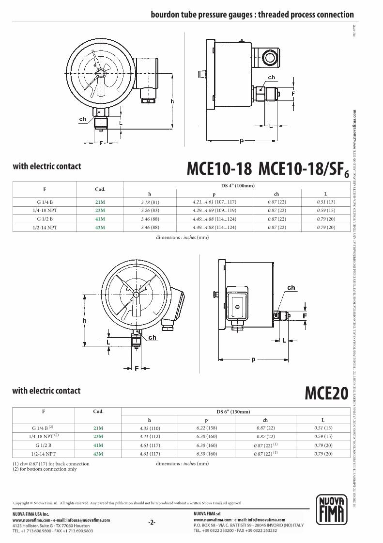
MCE10-18 MCE10-18/SF6
G 1/4 B
1/4-18 NPT
F
G 1/2 B
1/2-14 NPT
21M
23M
Cod.
41M
43M
h p ch L
MCE20
G 1/4 B (2)
1/4-18 NPT (2)
F
G 1/2 B
1/2-14 NPT
21M
23M
Cod.
41M
43M
h p Lch
RC2 -
07/1
5
bourdon tube pressure gauges : threaded process connection
DS 4” (100mm)
with electric contact
dimensions : inches (mm)
3.18 (81)
3.26 (83)
3.46 (88)
3.46 (88)
4.21...4.61 (107...117)
4.29...4.69 (109...119)
4.49...4.88 (114...124)
4.49...4.88 (114...124)
0.87 (22)
0.87 (22)
0.87 (22)
0.87 (22)
0.51 (13)
0.59 (15)
0.79 (20)
0.79 (20)
DS 6” (150mm)
with electric contact
(1) ch= 0.67 (17) for back connection(2) for bottom connection only
dimensions : inches (mm)
4.33 (110)
4.41 (112)
4.61 (117)
4.61 (117)
6.22 (158)
6.30 (160)
6.30 (160)
6.30 (160)
0.51 (13)
0.59 (15)
0.79 (20)
0.79 (20)
0.87 (22)
0.87 (22)
0.87 (22) (1)
0.87 (22) (1)
IN O
RD
ER
TO
IM
PR
OV
E T
HE
IR P
RO
DU
CT
ION
, ME
SSR
S. N
UO
VA
FIM
A R
ESE
RV
E T
HE
RIG
HT
TO
TH
EM
SELV
ES
TO
MA
KE
AL
L T
HE
MO
DIF
ICA
TIO
NS
TH
AT
TH
EY
DE
EM
IN
DIS
PE
NSA
BL
E A
T A
NY
TIM
E. U
PD
AT
ED
DA
TA
-SH
EE
TS
AR
E A
VA
ILA
BL
E O
N S
ITE
: ww
w.n
uo
vafi
ma.
com
Copyright © Nuova Fima srl. All rights reserved. Any part of this publication should not be reproduced without a written Nuova Fima’s srl approval
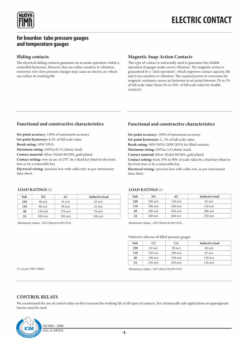
220
110
48
24
65 mA
130 mA
190 mA
250 mA
90 mA
180 mA
330 mA
450 mA
40 mA
85 mA
130 mA
150 mA
220
110
48
24
40 mA
80 mA
120 mA
200 mA
45 mA
90 mA
170 mA
350 mA
25 mA
45 mA
70 mA
100 mA
220
110
48
24
100 mA
200 mA
300 mA
400 mA
120 mA
240 mA
450 mA
600 mA
65 mA
130 mA
200 mA
250 mA
-1-ISO 9001 : 2008Cert. nr. 0433/6
for bourdon tube pressure gaugesand temperature gauges
Functional and constructive characteristics
Set-point accuracy: 150% of instrument accuracy.
Set-point hysteresys: 0,3% of full scale value.
Break rating: 10W/18VA.
Maximum rating: 250Vac/0,7A (ohmic load).
Contact material: Silver-Nickel 80/20%, gold plated.
Contact setting: over an arc of 270°, by a fixed key fitted to the front
lens or by a removable key.
Electrical wiring: junction box with cable exit, as per instrument
data-sheet.
Functional and constructive characteristics
Set-point accuracy: 150% of instrument accuracy.
Set-point hysteresys: 2...5% of full scale value.
Break rating: 30W/50VA (20W/20VA for filled version).
Maximum rating: 250Vac/1A (ohmic load).
Contact material: Silver-Nickel 80/20%, gold plated.
Contact setting: from 10% to 90% of scale value by a fixed key fitted to
the front lens or by a removable key.
Electrical wiring: junction box with cable exit, as per instrument
data-sheet.
LOAD RATINGS (1) LOAD RATINGS (1)
DC AC Inductive load
Minimum values : 24V/20mA/0,4W/4VA.
DC AC Inductive load
Minimum values : 24V/20mA/0,4W/4VA.
CC CA Inductive load
Minimum values : 24V/20mA/0,4W/4VA.(1) as per DIN 16085.
Dielectric silicone oil filled pressure gauges
We recommand the use of control relays as they increase the working life of all types of contacts. For intrinsecally safe applications an approppriate
barrier must be used.
CONTROL RELAYS
Sliding contactsThe electrical sliding contacts guarantee an accurate operation within a
controlled hysteresis. However they are rather sensitive to vibration,
moreover, very slow pressure changes may cause an electric arc which
can reduce its working life.
Magnetic Snap-Action ContactsThis type of contact is universally used to guarantee the reliable
operation of gauges under severe vibration. The magnetic action is
guaranteed by a "click operation", which improves contact capacity, life
and is less sensitive to vibration. The required power to overcome the
magnetic resistance causes an hysteresis at set-point between 2% to 5%
of full scale value (from 4% to 10% of full scale value for double
contacts).
Volt
Volt
Volt
ELECTRIC CONTACT

01S
02S
01D
02D
03D
04D
08D
09D
M1S
M2S
M1D
M2D
M3D
M4D
M8D
M9D
1°2°
1-
4+
3+
2-
1°2°
3+
4+
1-
2-
1°2°
1 3 2
1°2°
3 2 1
1°2°
1 2 3
1°2°
132
13
1 3
1 2 3
1 3
1 2 3
1 2 3
1 2 3
1 3 2 4
1 3 2 4
1 3
RC
3 -
07
/15
WIRING
SCHEME (1)
CONTACT CODE
slidingmagnetic
snap-action
ELECTRIC SCHEME
(before set)
CLOCKWISE MOVEMENT
OF THE POINTER CAUSES:
SINGLE CONTACT
DOUBLE CONTACT (2)
Opening
Closing
Opening 1
Closing 2
Closing 1
Closing 2
Closing 1
Opening 2
Opening 1
Opening 2
Opening 1
Closing 2
Closing 1
Closing 2
INDEPENDENT DOUBLE CONTACT (2)
(1) The above numbers are the same of those stamped on the junction box.
(2) Each contact must not exceed the next one.
for bourdon tube pressure gaugesand temperature gauges ELECTRIC CONTACT
MINI
MAXI
MAXI
MAXI
MINI
MAXI
MAXI
MAXI
MINI
MINI
MAXI
MINI
MAXI
MINI
IN O
RD
ER
TO
IM
PR
OV
E T
HE
IR P
RO
DU
CT
ION
, ME
SSR
S. N
UO
VA
FIM
A R
ESE
RV
E T
HE
RIG
HT
TO
TH
EM
SELV
ES
TO
MA
KE
AL
L T
HE
MO
DIF
ICA
TIO
NS
TH
AT
TH
EY
DE
EM
IN
DIS
PE
NSA
BL
E A
T A
NY
TIM
E. U
PD
AT
ED
DA
TA
-SH
EE
TS
AR
E A
VA
ILA
BL
E O
N S
ITE
: ww
w.n
uo
vafi
ma.
com
Copyright © Nuova Fima srl. All rights reserved. Any part of this publication should not be reproduced without a written Nuova Fima’s srl approval

E1
E2
E11
E12
E21
E22
1
+-
2
+-
4
2°
+-3
1°
+-
1
+-
2
+-
3+-
1
+-
2
+-
4
2°
+-3
1°
+-
1
+-
2
+-
3+-
1
+-
2
+-
4
2°
+-3
1°
+-
1
+-
2
+-
4
2°
+-3
1°
+-
MAXI
2+
31-
MINI
2+
3 1-
MAXI
MAXI
1-
3 2+
4
1°2°
MAXI
MINI
1-
3 2+
4
1°2°
MINI
MINI
2+
3 1-
4
1°2°
MINI
MAXI
1-
3 2+
4
1°2°
-1-ISO 9001 : 2008Cert. nr. 0433/6
Electronic contacts with PNP output
Switching accuracy: 1,5 times the instrument accuracy.
Switching hysteresis: 0,3...1% of full scale value.
Adjustement: over an arc of 270 °, through the knob placed on front
lens or through removable key.
Supply: 10...30 Vdc.
Switching current: max 100 mA
Temperature range: -25...+65°C
Electronic contacts are equipped with electrical distance sensors
(proximity sensors). The output signal is governed by the presence
or absence of a control vane moved by the actual value pointer in
the magnetic field of the proximity sensor.
The switching behaviour of the PNP switches used in these contacts
is normally defined as a “closer” (opposite to the inductive contacts).
Due to their proximity type of switching, respect to the traditional sliding
contact they offer better switching accuracy and extended service life.
They are properly designed to switch small DC load and so particularly
suitable for a direct wiring to PLC / PC direct input and to trigger
optoelectronic coupler.
Also they are the best preference for oil filled instruments to be installed in
the most severe operating conditions created by the ambient environments.
Open contact Closed contact
for pressure gauges and thermometersELECTRONIC CONTACTS
SINGLE CONTACT
DOUBLE CONTACT (2)
CONTACT CODEELECTRIC SCHEME
(before set)
CLOCKWISE MOVEMENT
OF THE POINTER CAUSES:
Closing
Opening
Closing 1
Closing 2
Closing 1
Opening 2
Opening 1
Closing 2
Opening 1
Opening 2
WIRING
SCHEME (1)
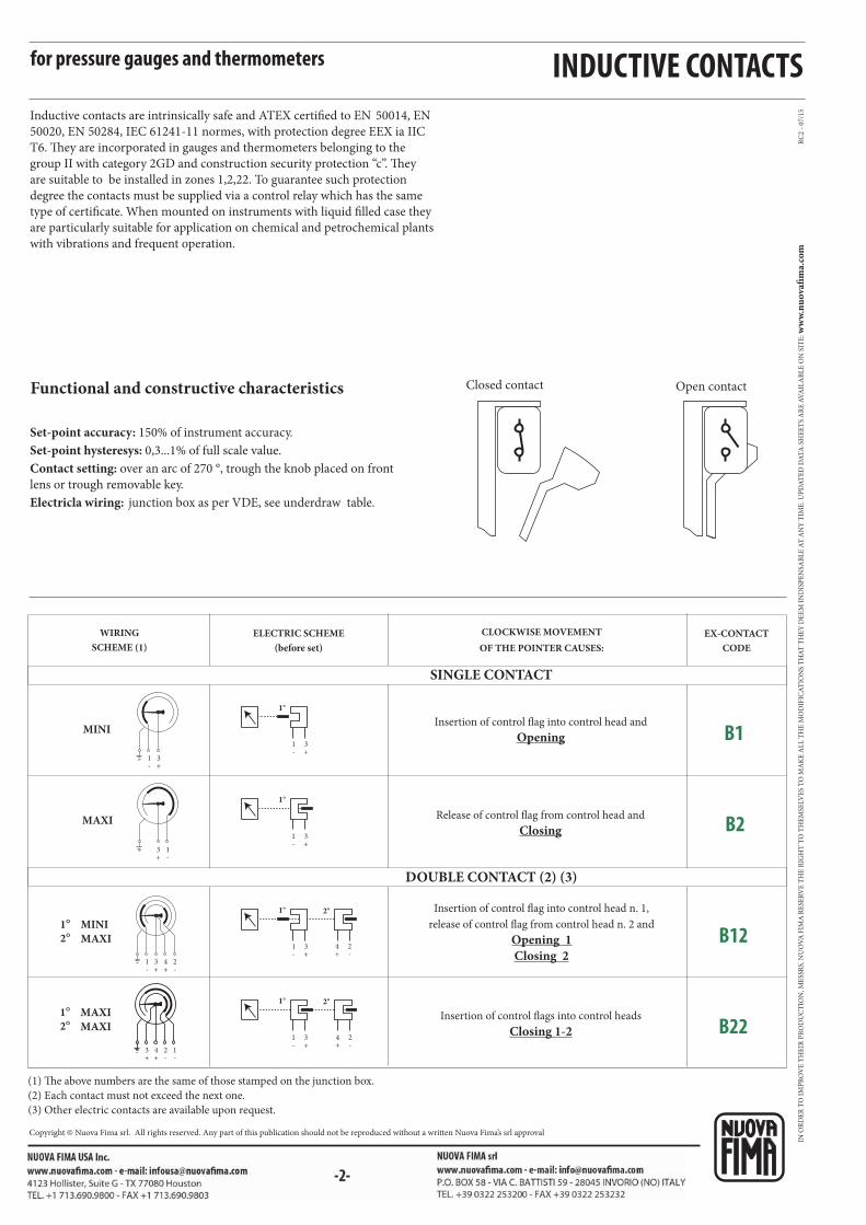
MAXI
1-
3+
MINI
1-
3+
MAXI
MAXI
3+
4+
1-
2-
1°2°
MINI
MAXI
1°2°
1-
3+
4+
2-
RC
2 -
07
/15
B1
B2
B12
B22
1-
3+
2°1°
4+
2-
1-
3+
1°
1-
3+
4+
2-
2°1°
1-
3+
1°
for pressure gauges and thermometers
Inductive contacts are intrinsically safe and ATEX certified to EN 50014, EN
50020, EN 50284, IEC 61241-11 normes, with protection degree EEX ia IIC
T6. They are incorporated in gauges and thermometers belonging to the
group II with category 2GD and construction security protection “c”. They
are suitable to be installed in zones 1,2,22. To guarantee such protection
degree the contacts must be supplied via a control relay which has the same
type of certificate. When mounted on instruments with liquid filled case they
are particularly suitable for application on chemical and petrochemical plants
with vibrations and frequent operation.
Functional and constructive characteristics
Set-point accuracy: 150% of instrument accuracy.
Set-point hysteresys: 0,3...1% of full scale value.
Contact setting: over an arc of 270 °, trough the knob placed on front
lens or trough removable key.
Electricla wiring: junction box as per VDE, see underdraw table.
WIRING
SCHEME (1)
ELECTRIC SCHEME
(before set)
EX-CONTACT
CODE
(1) The above numbers are the same of those stamped on the junction box.
(2) Each contact must not exceed the next one.
(3) Other electric contacts are available upon request.
CLOCKWISE MOVEMENT
OF THE POINTER CAUSES:
SINGLE CONTACT
DOUBLE CONTACT (2) (3)
Insertion of control flag into control head and
Opening
Release of control flag from control head and
Closing
Insertion of control flag into control head n. 1,
release of control flag from control head n. 2 and
Opening 1
Closing 2
Insertion of control flags into control heads
Closing 1-2
INDUCTIVE CONTACTS
Open contactClosed contact
IN O
RD
ER
TO
IM
PR
OV
E T
HE
IR P
RO
DU
CT
ION
, ME
SSR
S. N
UO
VA
FIM
A R
ESE
RV
E T
HE
RIG
HT
TO
TH
EM
SELV
ES
TO
MA
KE
AL
L T
HE
MO
DIF
ICA
TIO
NS
TH
AT
TH
EY
DE
EM
IN
DIS
PE
NSA
BL
E A
T A
NY
TIM
E. U
PD
AT
ED
DA
TA
-SH
EE
TS
AR
E A
VA
ILA
BL
E O
N S
ITE
: ww
w.n
uo
vafi
ma.
com
Copyright © Nuova Fima srl. All rights reserved. Any part of this publication should not be reproduced without a written Nuova Fima’s srl approval

MGS18-19-36
-1-
bourdon tube pressure gaugesall stainless steel constructionATEX versions,DS 4”, 6” (100-150mm)
Technical File: TF1 - Rev. 3
2G1 Version , Gas
4” and 6” (DS 100-150 mm) sizes are available, as standard version,
or fillable version for pressure ranges ≤ 6 bar.
They keep the same functional and constructive features as
MGS18-19-36 models. They differ from them as follows :
Ambient temperature: -22...+140 °F (-30...+60 °C).
Max process fluid temperature: see table (measured on the lowest
point of socket).
Protection degree: IP 55 as per EN 60529/IEC 529.
Windows: high resistance safety glass.
Socket: with restrictor.
Dial marking: CE Ex II 2G c TX X, year of manufacture, model
name and serial number.
Special dial: ranges different from standard, custom artworks and
dials without Nuova Fima logo are not available.
Options: plexiglas or tempered glass windows are not available.
Included documentation: Installation manual.
2D1 Version , Gas and Dust
4” and 6” (DS 100-150 mm) are available, as fillable version for
pressure ranges > 6 bar, or filled version.
They keep the same functional and constructive features as
MGS18-19-36 models. They differ from them as follows :
Damping liquids: glycerine 98%, silicon oil.
Ambient temperature:
+32...+140 °F (+0...+60 °C) for glycerine filling;
-22...+140 °F (-30...+60 °C) for silicon oil filling.
Max process fluid temperature: see table (measured on the lowest
point of socket).
Protection degree: IP 65 as per EN 60529/IEC 529.
Windows: high resistance safety glass.
Socket: with restrictor.
Dial marking: CE Ex II 2GD c TX X, year of manufacture, model
name and serial number.
Special dial: ranges different from standard, custom artworks and
dials without Nuova Fima logo are not available.
Options: plexiglas or tempered glass windows are not available.
Included documentation: Installation manual.
dry filled
Instrument caseClass
These instruments are designed for explosive atmospheres in food, processing, pharmaceutical, petrochemical industries and conventional and
nuclear power plants. The MGS pressure gauges are in conformity with the essential Health and Safety Requirements laid down in European
Directive 2014/34/UE for Group II, Category 2G or 2GD equipment in the T1...T6 temperature classes, as specified by EN 13463-1:2009 and
EN 13463-5:2011 standards. They are NOT suitable for ZONES 0 and 20.
T6 : 185°F (85°C) 158°F (70°C)
T5 : 212°F (100°C) 185°F (85°C)
T4 : 275°F (135°C) 248°F (120°C) 149°F (65°C)
T3 : 392°F (200°C)
T2 : 572°F (300°C) 302°F (150°C)
T1 : 842°F (450°C)
ISO 9001 : 2008Cert. nr. 0433/6
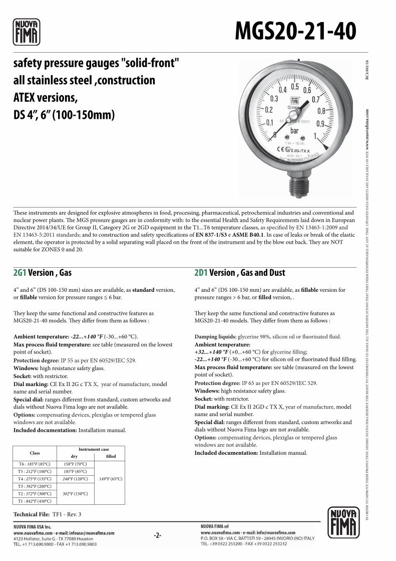
MGS20-21-40
RC
4 0
41
/16safety pressure gauges "solid-front"
all stainless steel ,constructionATEX versions,DS 4”, 6” (100-150mm)
Technical File: TF1 - Rev. 3
2G1 Version , Gas
4” and 6” (DS 100-150 mm) sizes are available, as standard version,
or fillable version for pressure ranges ≤ 6 bar.
They keep the same functional and constructive features as
MGS20-21-40 models. They differ from them as follows :
Ambient temperature: -22...+140 °F (-30...+60 °C).
Max process fluid temperature: see table (measured on the lowest
point of socket).
Protection degree: IP 55 as per EN 60529/IEC 529.
Windows: high resistance safety glass.
Socket: with restrictor.
Dial marking: CE Ex II 2G c TX X, year of manufacture, model
name and serial number.
Special dial: ranges different from standard, custom artworks and
dials without Nuova Fima logo are not available.
Options: compensating devices, plexiglas or tempered glass
windows are not available.
Included documentation: Installation manual.
2D1 Version , Gas and Dust
4” and 6” (DS 100-150 mm) are available, as fillable version for
pressure ranges > 6 bar, or filled version, .
They keep the same functional and constructive features as
MGS20-21-40 models. They differ from them as follows :
Damping liquids: glycerine 98%, silicon oil or fluorinated fluid.
Ambient temperature:
+32...+140 °F (+0...+60 °C) for glycerine filling;
-22...+140 °F (-30...+60 °C) for silicon oil or fluorinated fluid filling.
Max process fluid temperature: see table (measured on the lowest
point of socket).
Protection degree: IP 65 as per EN 60529/IEC 529.
Windows: high resistance safety glass.
Socket: with restrictor.
Dial marking: CE Ex II 2GD c TX X, year of manufacture, model
name and serial number.
Special dial: ranges different from standard, custom artworks and
dials without Nuova Fima logo are not available.
Options: compensating devices, plexiglas or tempered glass
windows are not available.
Included documentation: Installation manual. dry filled
Instrument caseClass
T6 : 185°F (85°C) 158°F (70°C)
T5 : 212°F (100°C) 185°F (85°C)
T4 : 275°F (135°C) 248°F (120°C) 149°F (65°C)
T3 : 392°F (200°C)
T2 : 572°F (300°C) 302°F (150°C)
T1 : 842°F (450°C)
These instruments are designed for explosive atmospheres in food, processing, pharmaceutical, petrochemical industries and conventional and
nuclear power plants. The MGS pressure gauges are in conformity with: to the essential Health and Safety Requirements laid down in European
Directive 2014/34/UE for Group II, Category 2G or 2GD equipment in the T1...T6 temperature classes, as specified by EN 13463-1:2009 and
EN 13463-5:2011 standards; and to construction and safety specifications of EN 837-1/S3 e ASME B40.1. In case of leaks or break of the elastic
element, the operator is protected by a solid separating wall placed on the front of the instrument and by the blow out back. They are NOT
suitable for ZONES 0 and 20.
IN O
RD
ER
TO
IM
PR
OV
E T
HE
IR P
RO
DU
CT
ION
, ME
SSR
S. N
UO
VA
FIM
A R
ESE
RV
E T
HE
RIG
HT
TO
TH
EM
SELV
ES
TO
MA
KE
AL
L T
HE
MO
DIF
ICA
TIO
NS
TH
AT
TH
EY
DE
EM
IN
DIS
PE
NSA
BL
E A
T A
NY
TIM
E. U
PD
AT
ED
DA
TA
-SH
EE
TS
AR
E A
VA
ILA
BL
E O
N S
ITE
: ww
w.n
uo
vafi
ma.
com

rograma de produção
NUOVA FIMA S.r.l. P.O. BOX 58 Via Cesare Battisti, 59
28045 Invorio (NO) ItalyTel. +39 0322.253200Fax +39 0322.253232