bowest library - electrical machine applications
TRANSCRIPT
8/3/2019 BOWest Library - Electrical Machine Applications
http://slidepdf.com/reader/full/bowest-library-electrical-machine-applications 1/11
OWest Library - Electrical Machine Applications
Library - Electrical Machine Applications
Contents
Notation
Transformers
Induction Machines
Synchronous Machines
Direct Current Machines
Efficiency
Temperature Rise Dielectric Dissipation Factor
Notation
The library uses the symbol font for some of the notation and formulae. If the symbols for the letters
alpha beta delta' do not appear here [a b d] then the symbol font needs to be installed before allnotation and formulae will be displayed correctly.
B E
G
k m N n P p R
susceptanceinduced voltagefrequencyconductancecurrent j-operatorcoefficientnumber of phasesnumber of turns
rotational speedpowerpole pairsresistance
[siemens, S][volts, V][hertz, Hz][siemens, S][amps, A]
[1∠90°][number][number][number]
[revs/min][watts, W][number]
[ohms, Ω]
S s T V X Y Z
d F
f h q w
voltamperessliptorqueterminal voltagereactanceadmittanceimpedanceloss anglemagnetic flux
phase angleefficiencytemperatureangular speed
[volt-amps, VA][per-unit][newton-metres, Nm][volts, V]
[ohms, Ω][siemens, S]
[ohms, Ω][degrees, °][webers, Wb]
[degrees, °][per-unit][centigrade, °C][radians/sec]
Transformers
For an ideal two-winding transformer with primary voltage V1 applied across N1 primary turns and
ttp://www.bowest.com.au/library/machines.html (1 of 11) [18/03/2008 1:09:09 PM]

8/3/2019 BOWest Library - Electrical Machine Applications
http://slidepdf.com/reader/full/bowest-library-electrical-machine-applications 2/11
OWest Library - Electrical Machine Applications
econdary voltage V2 appearing across N2 secondary turns:
V1 / V2 = N1 / N2
The primary current I1 and secondary current I2 are related by:
1 / I2 = N2 / N1 = V2 / V1
For an ideal step-down auto-transformer with primary voltage V1 applied across (N1 + N2) primary turns
and secondary voltage V2 appearing across N2 secondary turns:V1 / V2 = (N1 + N2) / N2
The primary (input) current I1 and secondary (output) current I2 are related by:
1 / I2 = N2 / (N1 + N2) = V2 / V1
Note that the winding current is I1 through the N1 section and (I2 - I1) through the N2 section.
For a single-phase transformer with rated primary voltage V1, rated primary current I1, rated secondary
voltage V2 and rated secondary current I2, the voltampere rating S is:
S = V1I1 = V2I2
For a balanced m-phase transformer with rated primary phase voltage V1, rated primary current I1, rate
econdary phase voltage V2 and rated secondary current I2, the voltampere rating S is:
S = mV1I1 = mV2I2
The primary circuit impedance Z1 referred to the secondary circuit for an ideal transformer with N1
primary turns and N2 secondary turns is:
Z12 = Z1(N2 / N1)2
The secondary circuit impedance Z2 referred to the primary circuit for an ideal transformer with N1
primary turns and N2 secondary turns is:
Z21 = Z2(N1 / N2)2
The voltage regulation DV2 of a transformer is the rise in secondary voltage which occurs when rated
oad is disconnected from the secondary with rated voltage applied to the primary. For a transformerwith a secondary voltage E2 unloaded and V2 at rated load, the per-unit voltage regulation DV2pu is:
DV2pu = (E2 - V2) / V2
Note that the per-unit base voltage is usually V2 and not E2.
Open Circuit Test
f a transformer with its secondary open-circuited is energised at rated primary voltage, then the input
power Poc represents the core loss (iron loss PFe) of the transformer:
ttp://www.bowest.com.au/library/machines.html (2 of 11) [18/03/2008 1:09:09 PM]
8/3/2019 BOWest Library - Electrical Machine Applications
http://slidepdf.com/reader/full/bowest-library-electrical-machine-applications 3/11
OWest Library - Electrical Machine Applications
Poc = PFe
The per-phase star values of the shunt magnetising admittance Ym, conductance Gm and susceptance
Bm of an m-phase transformer are calculated from the open-circuit test results for the per-phase primar
voltage V1oc, per-phase primary current I1oc and input power Poc using:
Ym = I1oc / V1oc
Gm = mV1oc2 / Poc
Bm = (Ym2 - Gm
2)½
Short Circuit Test
f a transformer with its secondary short-circuited is energised at a reduced primary voltage which
auses rated secondary current to flow through the short-circuit, then the input power Psc represents th
oad loss (primary copper loss P1Cu, secondary copper loss P2Cu and stray loss Pstray) of the
ransformer:Psc = P1Cu + P2Cu + Pstray
Note that the temperature rise should be allowed to stabilise because conductor resistance varies with
emperature.
f the resistance of each winding is determined by winding resistance tests immediately after the shortircuit test, then the load loss of an m-phase transformer may be split into primary copper loss P1Cu,
econdary copper loss P2Cu and stray loss Pstray:
P1Cu = mI1sc2R1star
P2Cu = mI2sc2R2star
Pstray = Psc - P1Cu - P2Cu
f the stray loss is neglected, the per-phase star values referred to the primary of the total seriesmpedance Zs1, resistance Rs1 and reactance Xs1 of an m-phase transformer are calculated from the
hort-circuit test results for the per-phase primary voltage V1sc, per-phase primary current I1sc and inpu
power Psc using:
Zs1 = V1sc / I1sc = Z1 + Z2(N12 / N2
2)
Rs1 = Psc / mI1sc2 = R1 + R2(N1
2 / N22)
Xs1 = (Zs12 - Rs1
2)½ = X1 + X2(N12 / N2
2)
where Z1, R1 and X1 are primary values and Z2, R2 and X2 are secondary values
Winding Resistance Test
The resistance of each winding is measured using a small direct current to avoid thermal and inductiveeffects. If a voltage Vdc causes current Idc to flow, then the resistance R is:
R = Vdc / Idc
ttp://www.bowest.com.au/library/machines.html (3 of 11) [18/03/2008 1:09:09 PM]
8/3/2019 BOWest Library - Electrical Machine Applications
http://slidepdf.com/reader/full/bowest-library-electrical-machine-applications 4/11
OWest Library - Electrical Machine Applications
f the winding under test is a fully connected balanced star or delta and the resistance measuredbetween any two phases is Rtest, then the equivalent winding resistances Rstar or Rdelta are:
Rstar = Rtest / 2
Rdelta = 3Rtest / 2
The per-phase star primary and secondary winding resistances R1star and R2star of an m-phase
ransformer may be used to calculate the separate primary and secondary copper losses P1Cu
and P2C
P1Cu = mI12R1star
P2Cu = mI22R2star
Note that if the primary and secondary copper losses are equal, then the primary and secondaryesistances R1star and R2star are related by:
R1star / R2star = I22 / I1
2 = N12 / N2
2
The primary and secondary winding resistances R1 and R2 may also be used to check the effect of stra
oss on the total series resistance referred to the primary, Rs1, calculated from the short circuit testesults:
Rs1 = R1 + R2(N12 / N2
2)
nduction Machines
The synchronous rotational speed ns and synchronous angular speed w s of a machine with p pole pair
unning on a supply of frequency fs are:
ns = 60fs / p
w s = 2pfs / p = 2pns / 60
The per-unit slip s of an induction machine of synchronous rotational speed ns running at rotational
peed nm is:
s = (ns - nm) / ns
Rearranging for rotational speed nm:
nm = (1 - s)ns
Using angular speed w instead of rotational speed n:
w m = (1 - s)w s
The rated load torque TM for a rated output power PM is:
TM = PM / w m = 60PM / 2pnm
ttp://www.bowest.com.au/library/machines.html (4 of 11) [18/03/2008 1:09:09 PM]

8/3/2019 BOWest Library - Electrical Machine Applications
http://slidepdf.com/reader/full/bowest-library-electrical-machine-applications 5/11
8/3/2019 BOWest Library - Electrical Machine Applications
http://slidepdf.com/reader/full/bowest-library-electrical-machine-applications 6/11
OWest Library - Electrical Machine Applications
The resistance of the stator winding is measured using a small direct current.
Synchronous Machines
The synchronous rotational speed ns and synchronous angular speed w s of a machine with p pole pair
unning on a supply of frequency fs are:ns = 60fs / p
w s = 2pfs / p
The output power Pm for a load torque Tm is:
Pm = w sTm
The rated load torque TM for a rated output power PM is:
TM = PM / w s = PMp / 2pfs = 60PM / 2pns
Synchronous Generator
For a synchronous generator with stator induced voltage Es, stator current Is and synchronous
mpedance Zs, the terminal voltage V is:
V = Es - IsZs = Es - Is(Rs + jXs)
where Rs is the stator resistance and Xs is the synchronous reactance
Synchronous Motor For a synchronous motor with stator induced voltage Es, stator current Is and synchronous impedance
Zs, the terminal voltage V is:
V = Es + IsZs = Es + Is(Rs + jXs)
where Rs is the stator resistance and Xs is the synchronous reactance
Note that the field excitation of a parallelled synchronous machine determines its power factor:an under-excited machine operates with a leading power factor,an over-excited machine operates with a lagging power factor.
The field excitation of an isolated synchronous generator determines its output voltage.
Direct Current Machines
Shunt Generator
For a shunt generator with armature induced voltage Ea, armature current Ia and armature resistance
Ra, the terminal voltage V is:
ttp://www.bowest.com.au/library/machines.html (6 of 11) [18/03/2008 1:09:09 PM]
8/3/2019 BOWest Library - Electrical Machine Applications
http://slidepdf.com/reader/full/bowest-library-electrical-machine-applications 7/11
OWest Library - Electrical Machine Applications
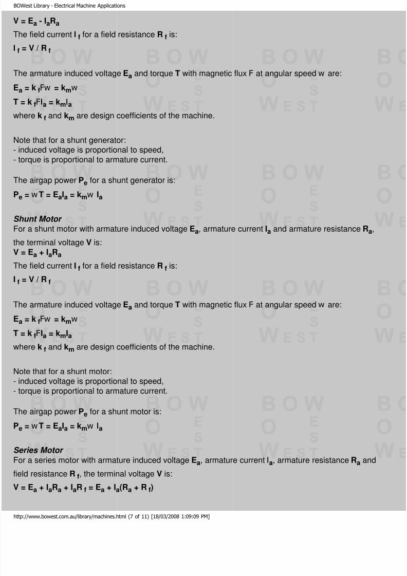
V = Ea - IaRa
The field current I f for a field resistance R f is:
f = V / R f
The armature induced voltage Ea and torque T with magnetic flux F at angular speed w are:
Ea = k fFw = kmw
T = k fFIa = kmIa
where k f and km are design coefficients of the machine.
Note that for a shunt generator:induced voltage is proportional to speed,
torque is proportional to armature current.
The airgap power Pe for a shunt generator is:
Pe = w T = EaIa = kmw Ia
Shunt Motor
For a shunt motor with armature induced voltage Ea, armature current Ia and armature resistance Ra,
he terminal voltage V is:
V = Ea + IaRa
The field current I f for a field resistance R f is:
f = V / R f
The armature induced voltage Ea and torque T with magnetic flux F at angular speed w are:
Ea = k fFw = kmw
T = k fFIa = kmIa
where k f and km are design coefficients of the machine.
Note that for a shunt motor:induced voltage is proportional to speed,
torque is proportional to armature current.
The airgap power Pe for a shunt motor is:
Pe = w T = EaIa = kmw Ia
Series Motor
For a series motor with armature induced voltage Ea, armature current Ia, armature resistance Ra and
eld resistance R f, the terminal voltage V is:
V = Ea + IaRa + IaR f = Ea + Ia(Ra + R f)
ttp://www.bowest.com.au/library/machines.html (7 of 11) [18/03/2008 1:09:09 PM]

8/3/2019 BOWest Library - Electrical Machine Applications
http://slidepdf.com/reader/full/bowest-library-electrical-machine-applications 8/11
OWest Library - Electrical Machine Applications
The field current is equal to the armature current.
The armature induced voltage Ea and torque T with magnetic flux F at angular speed w are:
Ea = k fFw Ia = kmw Ia
T = k fFIa2 = kmIa
2
where k f and km are design coefficients of the machine.
Note that for a series motor:induced voltage is proportional to both speed and armature current,
torque is proportional to the square of armature current,armature current is inversely proportional to speed for a constant induced voltage.
The airgap power Pe for a series motor is:
Pe = w T = EaIa = kmw Ia2
Efficiency
The per-unit efficiency h of an electrical machine with input power Pin, output power Pout and power
oss Ploss is:
h = Pout / Pin = Pout / (Pout + Ploss) = (Pin - Ploss) / Pin
Rearranging the efficiency equations:
Pin = Pout + Ploss = Pout / h = Ploss / (1 - h)
Pout = Pin - Ploss = hPin = hPloss / (1 - h)
Ploss = Pin - Pout = (1 - h)Pin = (1 - h)Pout / h
For an electrical machine with output power Pout (proportional to current) and power loss Ploss
omprising a fixed loss Pfix (independent of current) plus a variable loss Pvar (proportional to square of
urrent) the efficiency is a maximum when Pvar is equal to Pfix.
For a transformer, Pfix is the iron loss and Pvar is the copper loss plus the stray loss.
For an induction machine, Pfix is the iron loss plus the mechanical loss and Pvar is the copper loss plus
he stray loss.
Energy Conversion
Comparing megawatt-hours and gigajoules, 1 MWh is equivalent to 3.6 GJ. For an energy conversion
process with a per-unit efficiency h, 1 MWh of energy output is obtained from (3.6 / h) GJ of energynput.
ttp://www.bowest.com.au/library/machines.html (8 of 11) [18/03/2008 1:09:09 PM]

8/3/2019 BOWest Library - Electrical Machine Applications
http://slidepdf.com/reader/full/bowest-library-electrical-machine-applications 9/11
OWest Library - Electrical Machine Applications
Temperature Rise
The resistance of copper and aluminium windings increases with temperature, and the relationship isquite linear over the normal range of operating temperatures. For a linear relationship, if the winding
esistance is R1 at temperature q1 and R2 at temperature q2, then:
R1 / (q1 - q0) = R2 / (q2 - q0) = (R2 - R1) / (q2 - q1)
where q0 is the extrapolated temperature for zero resistance.
The ratio of resistances R2 and R1 is:
R2 / R1 = (q2 - q0) / (q1 - q0)
The average temperature rise Dq of a winding under load may be estimated from measured values of
he cold winding resistance R1
at temperature q1
(usually ambient temperature) and the hot winding
esistance R2 at temperature q2, using:
Dq = q2 - q1 = (q1 - q0) (R2 - R1) / R1
Rearranging for per-unit change in resistance DRpu relative to R1:
DRpu = (R2 - R1) / R1 = (q2 - q1) / (q1 - q0) = Dq / (q1 - q0)
Note that the resistance values are measured using a small direct current to avoid thermal and inductiveeffects.
Copper Windings
The value of q0 for copper is - 234.5 °C, so that:
Dq = q2 - q1 = (q1 + 234.5) (R2 - R1) / R1
f q1 is 20 °C and Dq is 1 degC:
DRpu = (R2 - R1) / R1 = Dq / (q1 - q0) = 1 / 254.5 = 0.00393
The temperature coefficient of resistance of copper at 20 °C is 0.00393 per degC.
Aluminium Windings
The value of q0 for aluminium is - 228 °C, so that:
Dq = q2 - q1 = (q1 + 228) (R2 - R1) / R1
f q1 is 20 °C and Dq is 1 degC:
DRpu = (R2 - R1) / R1 = Dq / (q1 - q0) = 1 / 248 = 0.00403
The temperature coefficient of resistance of aluminium at 20 °C is 0.00403 per degC.
ttp://www.bowest.com.au/library/machines.html (9 of 11) [18/03/2008 1:09:09 PM]

8/3/2019 BOWest Library - Electrical Machine Applications
http://slidepdf.com/reader/full/bowest-library-electrical-machine-applications 10/11
OWest Library - Electrical Machine Applications
Note that aluminium has 61% of the conductivity and 30% of the density of copper, therefore for the
ame conductance (and same resistance) an aluminium conductor has 164% of the cross-sectionalarea, 128% of the diameter and 49% of the mass of a copper conductor.
Dielectric Dissipation Factor
f an alternating voltage V of frequency f is applied across an insulation system comprising capacitance
C and equivalent series loss resistance RS, then the voltage VR across RS and the voltage VC across C
due to the resulting current I are:
VR = IRS
VC = IXC
V = (VR2 + VC
2)½
The dielectric dissipation factor of the insulation system is the tangent of the dielectric loss angle d between VC and V:
and = VR / VC = RS / XC = 2pfCRS
RS = XCtand = tand / 2pfC
Note that an increase in the dielectric losses of a insulation system (from an increase in the series loss
esistance RS) results in an increase in tand. Note also that tand increases with frequency.
The dielectric power loss P is related to the capacitive reactive power QC by:
P = I2
RS = I2
XCtand = QCtand
The power factor of the insulation system is the cosine of the phase angle f between VR and V:
cosf = VR / V
o that d and f are related by:
d + f = 90°
and and cosf are related by:
and = 1 / tanf = cosf / sinf = cosf / (1 - cos2f )½
o that when cosf is close to zero, tand » cosf
Note that the series loss resistance RS is not related to the shunt leakage resistance of the insulation
ystem (which is measured using direct current).
Page Access
Count since 07
Updated 07 September 2001Copyright ©1999-2001 BOWest Pty Ltd
ttp://www.bowest.com.au/library/machines.html (10 of 11) [18/03/2008 1:09:09 PM]

8/3/2019 BOWest Library - Electrical Machine Applications
http://slidepdf.com/reader/full/bowest-library-electrical-machine-applications 11/11
OWest Library - Electrical Machine Applications
Please refer to the disclaimer and copyright notices before using this information
Home | Staff | Library | Links | Feedback | Email