boyle energy services echnology, inc · garett jennison - boyle energy services & technology,...
TRANSCRIPT

BOYLE ENERGY SERVICES & TECHNOLOGY, INC.
© Boyle Energy Services & Technology 2013
Accelerated ACC and Steam System Commissioning at a Large Gas-To-Liquids Facility
ACC Users Group -- 16 October 2013
Tom Guidry - KBR
Garett Jennison - Boyle Energy Services & Technology, Inc.

© Boyle Energy Services & Technology 2013
Abstract
A petrochemical consortium constructed a large Gas-to-Liquids processing facility in Delta State, Nigeria and needed a new way to commission the facilities steam systems. Demineralized water constraints were predicted to result in unacceptably long durations should atmospheric steam blows be implemented. The consortium elected to implement the SigmaBlow™ protocol to reduce the steam blow duration. SigmaBlow ™ enables condensate capture during the steam blow and provides for cleaning and passivating of all steam/condensate flow paths. During this SigmaBlow™ protocol, the steam system supporting five waste heat boilers, two process boilers, three package boilers, nine steam turbines, and process steam users was effectively and expeditiously cleaned and commissioned. Six Air Cooled Condensers of varying sizes and designs were also cleaned and used in commissioning the rest of the steam systems. The design details, advantages and savings in demineralized water, fuel and schedule are detailed in this presentation.

© Boyle Energy Services & Technology 2013
Gas to Liquids (GTL) Overview
HP Boiler IP Boiler
Fired Superheater
Steam Turbine Air Compressors
Cryogenic Air Separation
Steam Turbine Generators
Steam Turbine Process Compressors
A Frame ACCs A Frame ACCs Horizontal ACCs
Horizontal ACC

© Boyle Energy Services & Technology 2013
Escravos GTL Site - 3D Model
ASU ACC
STG ACCs Horizontal
ACCs
Steam System Footprint- 860m x 350m x 60m

© Boyle Energy Services & Technology 2013
Escravos GTL Project / CCPP Comparison
“F” 2x1 CCPP Escravos GTL
Steam Production
Steam Turbines
Steam Generators
Targeted Piping Volume
Air Cooled Condensers
900m3
2000 tph
9
10
10
170m3
500 tph
1
2
1

© Boyle Energy Services & Technology 2013
Conventional Steam Blow vs. Admission Criteria
Transition Steam System from a Construction Environment to an Operating Environment • Cleaning Force Ratios Greater than Unity (Typical OEM
Specification is CFR >1.2) • ‘Dirty’ Targets Indicate Harmful Material is Being
Removed • Clean Targets Prove System Cleanliness

© Boyle Energy Services & Technology 2013
Conventional Steamblow Challenges
GTL Operating Condition Conventional Steamblow
• Generating Condensate • Consumes Condensate
• Clean Condensate Required
• Steady State Operation • Discontinuous Operation
• High Contamination Levels in ACC Following Steamblow
SigmaBlow™ Addresses Conventional Steamblow
Challenges Using ACCs

© Boyle Energy Services & Technology 2013
SigmaBlow™ Methodology - ACC

© Boyle Energy Services & Technology 2013
Gross Debris Removed Before ACC Steam Admission

© Boyle Energy Services & Technology 2013
Spring Return Fail-Safe Valves Provide ACC Protection
Quickly Isolates ACC from Steam Flow in the Event of Process Excursion or Black Plant Prevents Permanent Rupture Disks from Bursting
© Boyle Energy Services & Technology 2013
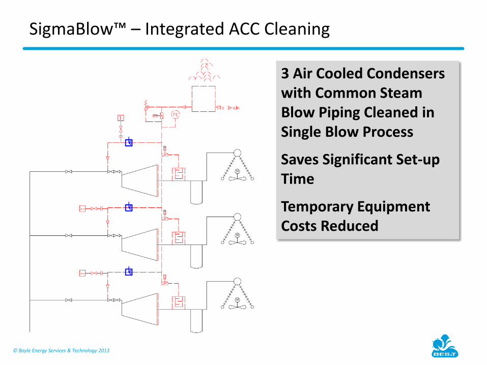
SigmaBlow™ – Integrated ACC Cleaning
3 Air Cooled Condensers with Common Steam Blow Piping Cleaned in Single Blow Process
Saves Significant Set-up Time
Temporary Equipment Costs Reduced

© Boyle Energy Services & Technology 2013
Common Piping for 3 ACC’s

© Boyle Energy Services & Technology 2013
ACC Cleaning Integrated with Steam Blow
5 A-Frame ACC’s were Operated in Parallel
Selective Fan Operation Focused Steam Flow on Individual ACCs
Steam Flow to Individual ACCs Exceed MCR Flow
Heavy Solids Rapidly Flushed from Cells • Initial Condensate Routed to Waste • Temporary Filtration Removes Suspended Solids • Dissolved Solids Removed by Boiler Blowdown

© Boyle Energy Services & Technology 2013
Condensate Handling - Single ACC
Condensate from ACC
Condensate After Filter

© Boyle Energy Services & Technology 2013
Condensate Handling Hardware
© Boyle Energy Services & Technology 2013
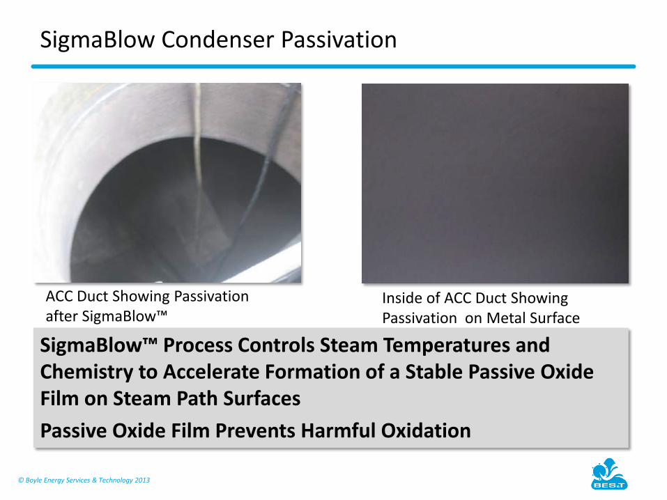
SigmaBlow Condenser Passivation
SigmaBlow™ Process Controls Steam Temperatures and Chemistry to Accelerate Formation of a Stable Passive Oxide Film on Steam Path Surfaces Passive Oxide Film Prevents Harmful Oxidation
ACC Duct Showing Passivation after SigmaBlow™
Inside of ACC Duct Showing Passivation on Metal Surface

© Boyle Energy Services & Technology 2013
Demonstrated SigmaBlow™ Schedule Compression
SigmaBlow™ Duration 1159 Calendar Hours
Equipment Delays 455 Calendar Hours
Reconfiguration 188 Calendar Hours
SigmaBlow™ Schedule Potential 516 Calendar Hours
Original Plan was for a 4200 Calendar Hour Conventional Steam Blow
Demineralized Water Savings in Excess of 116,000 Tons
100’s of Billions of BTU’s Fuel Savings

© Boyle Energy Services & Technology 2013
Lessons Learned – Design-for-Commissioning™
Multiple Temporary Connections Added to Condenser in the Field >> Incorporate During Design Phase to Reduce Field Work
ACC Blanking Plates Required Modification to Perform SigmaBlow™ >> Specify Blanking Plates for Full Vacuum During Design Phase when Required
ACC Steam Jet Air Ejectors Required During Commissioning >> Must Design for this Condition

© Boyle Energy Services & Technology 2013
Thank You