bp pilot bp pilot ——project review - epa.gov ™ remvue®® bp background bp...
TRANSCRIPT

SlipStream™SlipStreamSlipStream™™
REMREMVueVue®®
BP Pilot BP Pilot ——Project ReviewProject Review
**
* Patents Pending
SlipStream™SlipStreamSlipStream™™
REMREMVueVue®®
BP BackgroundBP BackgroundBP Canada operates in AB and NE BC.>90% of its production is natural gas.Compressor combustion emissions are our #1 emitter. Fugitives are #2.Significant push for quantifying and reducing its fugitive and vented emissions.BP Canada has over 250 compressor engines. ~20% have REMREMVueVue®® control panels, most with Air Fuel management control.

SlipStream™SlipStreamSlipStream™™
REMREMVueVue®®720 miles
760 miles
2
BP Canada E&P OperationsBP Canada E&P Operations

SlipStream™SlipStreamSlipStream™™
REMREMVueVue®®
Emission Projections ProvincialEmission Projections Provincial
0
50
100
150
200
250
300
BC AB SK MB ON QUE NB NS PEI
199020002020
http://environment.gov.ab.ca/info/library/5892.ppt

SlipStream™SlipStreamSlipStream™™
REMREMVueVue®®
SlipStream™ is the REM Technology product* designed for utilizing vented vented hydrocarbonshydrocarbons as a supplementary fuel source for natural gas engines

SlipStream™SlipStreamSlipStream™™
REMREMVueVue®®
Design Objectives for SlipStreamDesign Objectives for SlipStream™™
Develop a technology that would allow vented hydrocarbons to be used as supplementary fuel for natural gas enginesMust not reduce performance or reliability of engineMust be scaleable from low volumes of supplementary fuel to high volumesMust be able to compensate (Air-Fuel Ratio and Governor)for variable flow and BTU value of the supplementary fuelMust be able to handle diluted and undiluted sourcesMust be safe — Safety FirstSafety First
SlipStream™SlipStreamSlipStream™™
REMREMVueVue®®
Pilot Site SelectionPilot Site SelectionEngaged workforceHas a source that can be easily capturedSite with existing REMREMVueVue®® AFR control PanelMinimally affect production during testing and commissioning

SlipStream™SlipStreamSlipStream™™
REMREMVueVue®®
Initial Site DetailsInitial Site DetailsSlipStreamSlipStream™™ Sources:Sources:
Packing Vent Gas (Diluted)Available from 3 unitsIncludes packing/distance piece vents and drainsProcess gas is sweet natural gasHeaders located in main building adjacent to compressors
VRU Gas (Undiluted)Flash gas collected from Gas Boot feeds 1st
stage suction of VRU (more than 2x btuvalue)Make-up gas system supplements VRU when there is insufficient gas from the Gas BootVRU building located ≈ 45 m from Waukesha compressor buildingExisting pipe and pipe rack
Gas BootGas BootVRUVRUBuildingBuilding
Packing Packing Vent Vent
HeaderHeader

SlipStream™SlipStreamSlipStream™™
REMREMVueVue®®
Initial Site DetailsInitial Site Details
Three Waukesha 9390 engines (2× GSI, 1× GL)
Two units running continuously ≈ 50–60 % loadedThird unit functions as backupAdjacent White-Superior no longer usedPre-existing REMREMVueVue®®–– 500500/AS/AS system on Unit #2
Unit 2 Unit 2 –– Waukesha 9390 GSI with Waukesha 9390 GSI with REMREMVueVue®® RichRich--toto--Lean AFRLean AFR

SlipStream™SlipStreamSlipStream™™
REMREMVueVue®®
Installation DetailsInstallation Details
SlipStream™SlipStreamSlipStream™™
REMREMVueVue®®
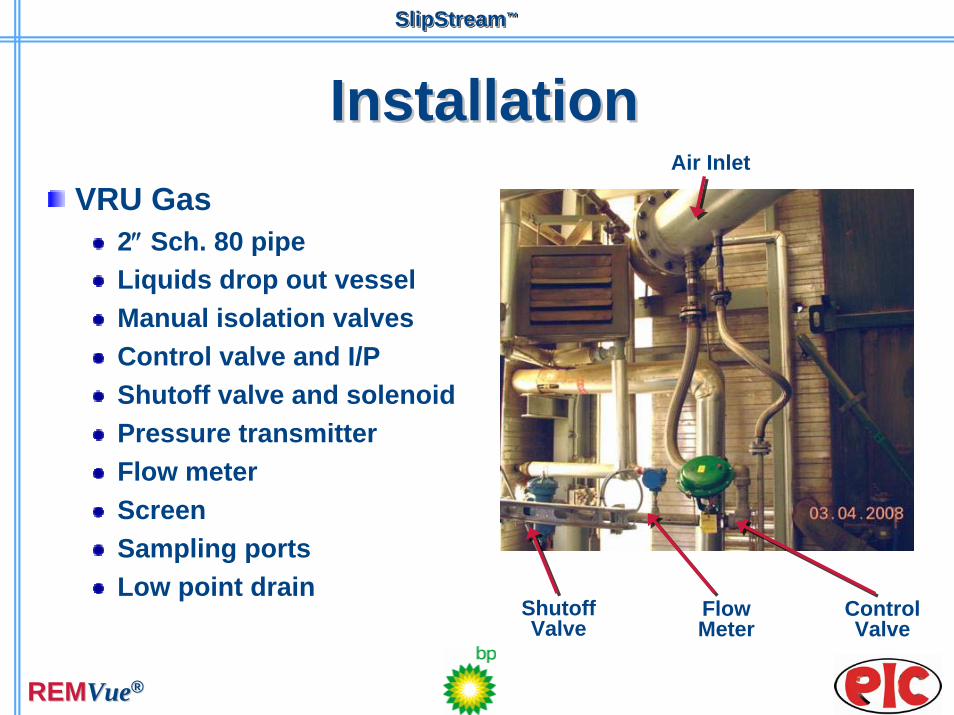
InstallationInstallationVRU Gas
2″ Sch. 80 pipeLiquids drop out vesselManual isolation valvesControl valve and I/PShutoff valve and solenoidPressure transmitterFlow meterScreenSampling portsLow point drain
Control Valve
Shutoff Valve
Flow Meter
Air Inlet

SlipStream™SlipStreamSlipStream™™
REMREMVueVue®®
InstallationInstallationPacking Vent Gas
1″ Sch. 80 pipe Control valve and I/P Manual isolation valveSampling portsPacking vent filter (optional)Packing vent thermocoupleWide range lambda sensor hardware
Control Control ValveValve
Packing Packing VentVent
Seal Seal PotPot

SlipStream™SlipStreamSlipStream™™
REMREMVueVue®®
InstallationInstallation

SlipStream™SlipStreamSlipStream™™
REMREMVueVue®®
Safety ReviewSafety Review

SlipStream™SlipStreamSlipStream™™
REMREMVueVue®®
SafetySafetyAny given SlipStream™ system may have one or more undiluted and/or diluted sources that may interface with any number of existing site processes and associated equipment. Given the diversity of processes and equipment in the field, it is crucial that a site-specific HAZOP is conducted.The complexity of the SlipStream™ design will depend on the type of SlipStream™ system, amount of flow, gas quality, expected process fluctuations, upstream equipment, etc. The safe operation of the SlipStream™ System is the primary design objective.
SlipStream™SlipStreamSlipStream™™
REMREMVueVue®®
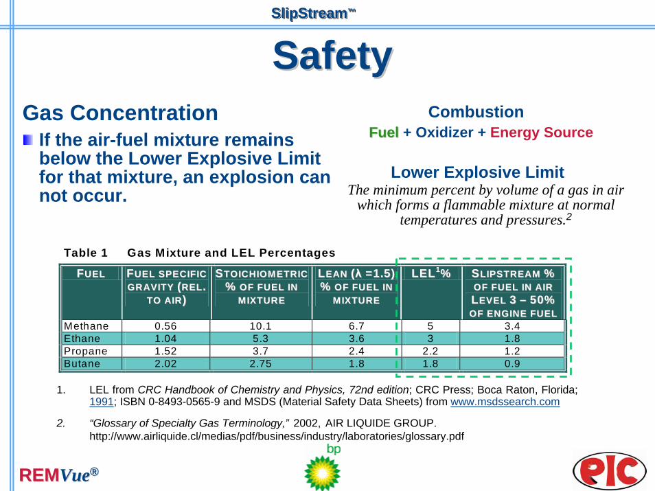
SafetySafetyGas Concentration
If the air-fuel mixture remains below the Lower Explosive Limit for that mixture, an explosion can not occur.
FuelFuel + Oxidizer + Energy Source
Table 1 Gas Mixture and LEL Percentages
FFUUEELL FFUUEELL SSPPEECCIIFFIICC GGRR AAVVIITTYY ((RREELL..
TTOO AAIIRR))
SSTTOOIICCHHIIOOMM EETTRRIICC %% OOFF FFUUEELL IINN
MM IIXXTTUURREE
LLEEAANN ((λλ ==11..55)) %% OOFF FFUUEELL IINN
MM IIXXTTUURREE
LLEELL11%% SSLLIIPPSSTTRREEAAMM %% OOFF FFUUEELL IINN AAIIRR LLEEVVEELL 33 –– 5500%% OOFF EENNGGIINNEE FFUUEELL
Methane 0.56 10.1 6.7 5 3.4 Ethane 1.04 5.3 3.6 3 1.8 Propane 1.52 3.7 2.4 2.2 1.2 Butane 2.02 2.75 1.8 1.8 0.9
1. LEL from CRC Handbook of Chemistry and Physics, 72nd edition; CRC Press; Boca Raton, Florida; 1991; ISBN 0-8493-0565-9 and MSDS (Material Safety Data Sheets) from www.msdssearch.com
2. “Glossary of Specialty Gas Terminology,” 2002, AIR LIQUIDE GROUP. http://www.airliquide.cl/medias/pdf/business/industry/laboratories/glossary.pdf
The minimum percent by volume of a gas in air which forms a flammable mixture at normal
temperatures and pressures.2
Lower Explosive Limit
Combustion

SlipStream™SlipStreamSlipStream™™
REMREMVueVue®®
BP SlipStreamBP SlipStream™™
PPRELIMINARYRELIMINARY RRESULTSESULTSANDAND LLESSONSESSONS LLEARNEDEARNED

SlipStream™SlipStreamSlipStream™™
REMREMVueVue®®
Engine Fuel FlowsEngine Fuel FlowsEngine Fuel Flows - BP Ricunus 4-11
0
50
100
150
200
250
11:33:00 11:33:30 11:34:00 11:34:30 11:35:00 11:35:30 11:36:00
Time hh:mm:ss
Flow
kg.
h
SlipStream Flow (VRU)Main Fuel FlowTotal Fuel Flow
SlipStream flow turned off
SlipStream flow turned on

SlipStream™SlipStreamSlipStream™™
REMREMVueVue®®
RPM Under Capacity ControlRPM Under Capacity Control
BP Ricinus 4-11 SlipStream Flows RPM under Capacity Control
020
406080
100
120140160
180200
14:06:15 14:06:30 14:06:45 14:07:00 14:07:15 14:07:30 14:07:45
Time
kg/h
Flo
w; K
pa P
ress
ure
800820
840860880900
920940960
9801000
RPM
VRU Pressure kPaFlow from VRU legMain Fuel FlowRPM
SlipStream™SlipStreamSlipStream™™
REMREMVueVue®®
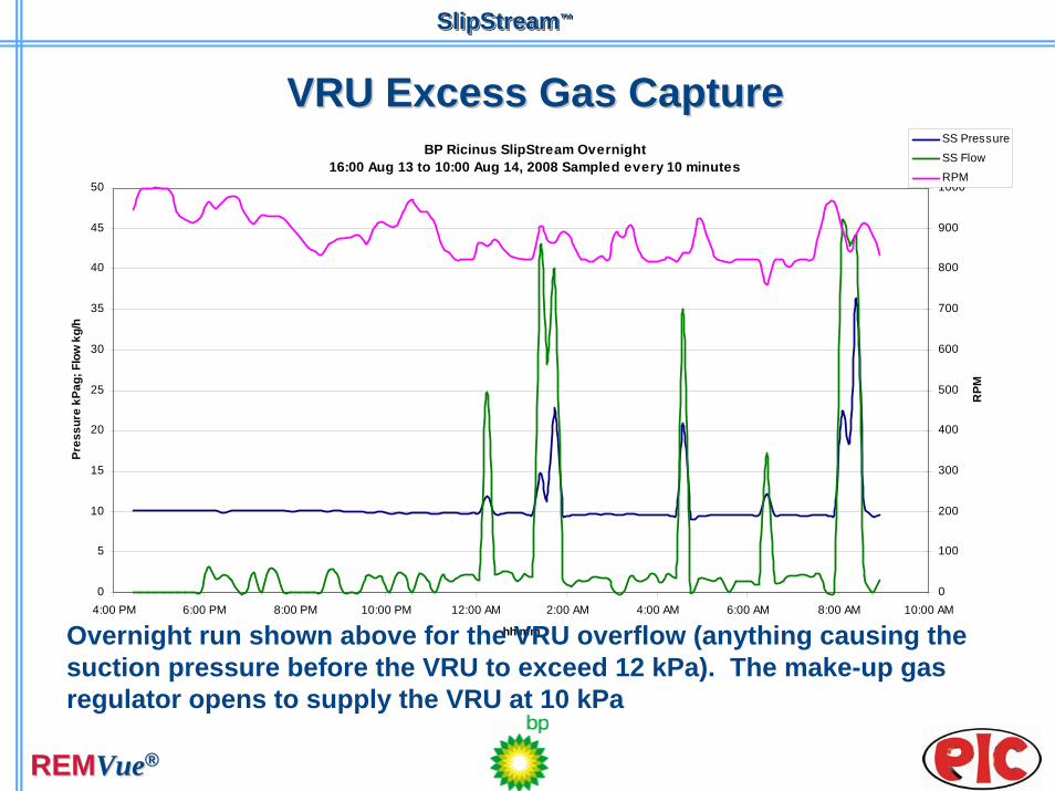
VRU Excess Gas CaptureVRU Excess Gas CaptureBP Ricinus SlipStream Overnight
16:00 Aug 13 to 10:00 Aug 14, 2008 Sampled every 10 minutes
0
5
10
15
20
25
30
35
40
45
50
4:00 PM 6:00 PM 8:00 PM 10:00 PM 12:00 AM 2:00 AM 4:00 AM 6:00 AM 8:00 AM 10:00 AM
hh:mm
Pres
sure
kPa
g; F
low
kg/
h
0
100
200
300
400
500
600
700
800
900
1000
RPM
SS Pressure
SS FlowRPM
Overnight run shown above for the VRU overflow (anything causing the suction pressure before the VRU to exceed 12 kPa). The make-up gas regulator opens to supply the VRU at 10 kPa

SlipStream™SlipStreamSlipStream™™
REMREMVueVue®®
Control Test ResultsControl Test Results(from first SS installation at another CDN gas company)(from first SS installation at another CDN gas company)
This next graph shows a trend of the engine RPM, SlipStream™ Flow and main fuel flowThe SlipStream™ flow is turned off and on abruptly to observe how the REMREMVueVue®® control system handles this sudden change in fuel to the engineIn addition to the trend graph, two videos of these events were taken with a FLIR infrared cameraThe videos show the vent pipe at the top of the engine building when the SlipStream™ Flow is turn on and off per the trend graphThis FLIR shows methane leaks that are invisible to the naked eye.

SlipStream™SlipStreamSlipStream™™
REMREMVueVue®®
SlipStreamSlipStream™™ ResultsResults
Minimal engine RPM changeFull vented flow turnedoff abruptly, then on abruptly

SlipStream™SlipStreamSlipStream™™
REMREMVueVue®®
ControlControlSlipStream™ uses advanced control algorithms to anticipate changes in SlipStream flow and adjusts the governor and air-fuel ratio control accordingly
The result — no impact to engine reliability or speed from:
Load changesSlipStream™ FlowFuel gas or SlipStream™ gas BTU swingsAmbient air temperature or pressure
SlipStream™SlipStreamSlipStream™™
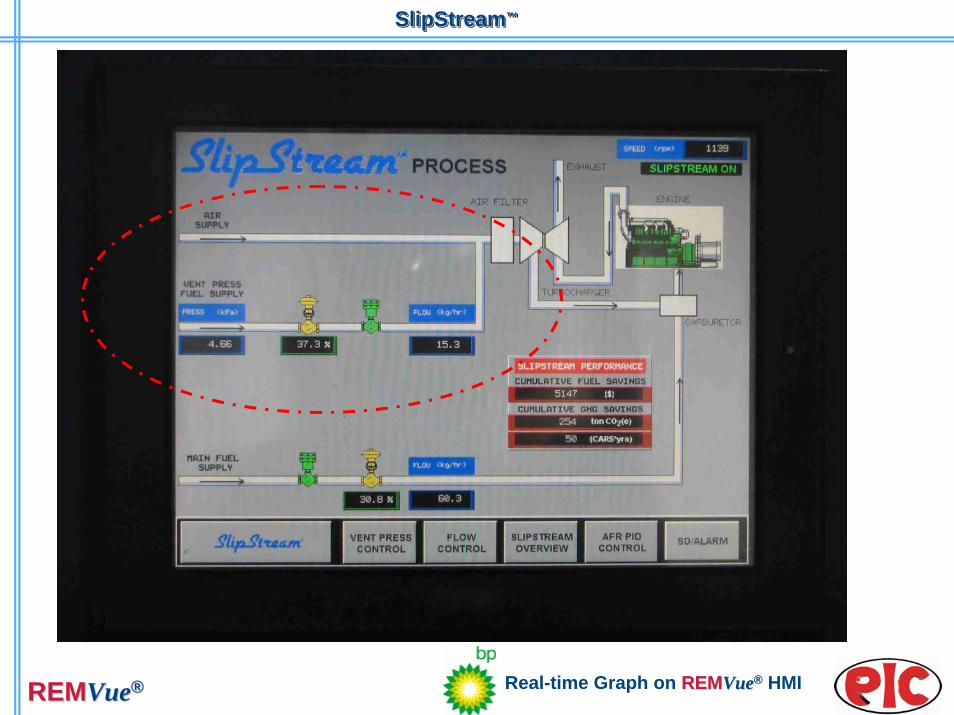
REMREMVueVue®® Real-time Graph on REMREMVueVue®® HMI

SlipStream™SlipStreamSlipStream™™
REMREMVueVue®®
BP Preliminary ResultsBP Preliminary ResultsAFR upgrade and SlipStream™ installation completeAFR Control
Relocation of governor control, addition of a DVC, and the implementation of new tuning techniques have led to significant improvement in engine governor response
Packing Vent GasDiluted flow control implementation is a success!By collecting the packing vent gas from only one unit, 4 kg/hr4 kg/hr or approximately 2%2% of the engine’s normal fuel flow was savedEquates to approximately $11,000/yr in potential fuel cost savings and a reduction of 625 tonnes CO2(e)/yr625 tonnes CO2(e)/yr
VRU GasSlipStream fuel rates of up to 50 kg/hr50 kg/hr or approximately 25%25% were achieved using gas from the VRU suctionEquates to approximately $137,500/yr* in potential fuel cost savings

SlipStream™SlipStreamSlipStream™™
REMREMVueVue®®
Lessons LearnedLessons LearnedAn audit of each unit’s “as found” operational and health issues is required prior to SlipStream™ implementation
Need for improved site coordination and project documentation during system installation
SlipStream™ source characteristics — amount, pressure, BTU content, etc. must be clearly understood
More specific pipe routing instructions are required to minimizeflow restrictions
Fast governor response is necessary to minimize speed upsets due to SlipStream™ transients
Main fuel flow meter selection — Thermal vs. Coriolis
SlipStream™ flow meter placement and control valve selection
SlipStream™SlipStreamSlipStream™™
REMREMVueVue®®
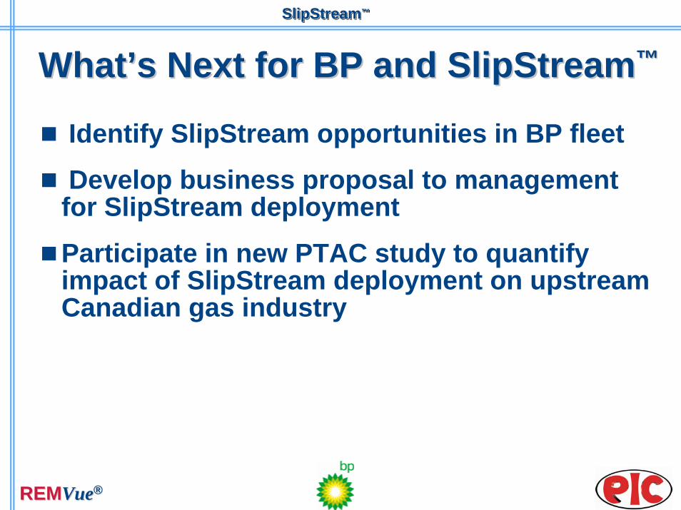
WhatWhat’’s Next for BP and SlipStreams Next for BP and SlipStream™™
Identify SlipStream opportunities in BP fleet
Develop business proposal to management for SlipStream deployment
Participate in new PTAC study to quantify impact of SlipStream deployment on upstream Canadian gas industry

SlipStream™SlipStreamSlipStream™™
REMREMVueVue®®
Thank YouThank YouThank You