bp range product information - cre technology · 29 ~33v 15 ~16.5v 30 ~ 36v ... 65.5x 125.2 x 100mm...
TRANSCRIPT
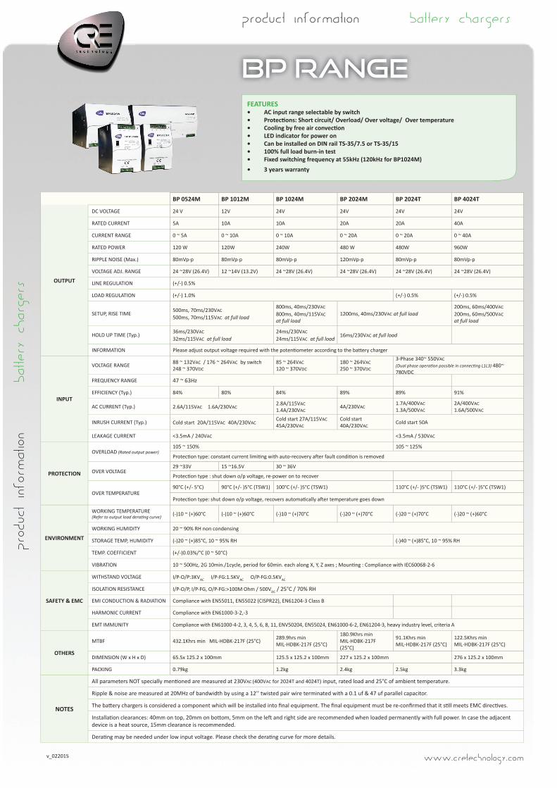
BP RANGEFEATURES• AC input range selectable by switch• Protecti ons: Short circuit/ Overload/ Over voltage/ Over temperature• Cooling by free air convecti on• LED indicator for power on• Can be installed on DIN rail TS-35/7.5 or TS-35/15• 100% full load burn-in test• Fixed switching frequency at 55kHz (120kHz for BP1024M)• 3 years warranty
BP 0524M BP 1012M BP 1024M BP 2024M BP 2024T BP 4024T
OUTPUT
DC VOLTAGE 24 V 12V 24V 24V 24V 24V
RATED CURRENT 5A 10A 10A 20A 20A 40A
CURRENT RANGE 0 ~ 5A 0 ~ 10A 0 ~ 10A 0 ~ 20A 0 ~ 20A 0 ~ 40A
RATED POWER 120 W 120W 240W 480 W 480W 960W
RIPPLE NOISE (Max.) 80mVp-p 80mVp-p 80mVp-p 120mVp-p 80mVp-p 80mVp-p
VOLTAGE ADJ. RANGE 24 ~28V (26.4V) 12 ~14V (13.2V) 24 ~28V (26.4V) 24 ~28V (26.4V) 24 ~28V (26.4V) 24 ~28V (26.4V)
LINE REGULATION (+/-) 0.5%
LOAD REGULATION (+/-) 1.0% (+/-) 0.5% (+/-) 0.5%
SETUP, RISE TIME 500ms, 70ms/230VAC 500ms, 70ms/115VAC at full load
800ms, 40ms/230VAC 800ms, 40ms/115VAC at full load
1200ms, 40ms/230VAC at full load200ms, 60ms/400VAC 200ms, 60ms/500VACat full load
HOLD UP TIME (Typ.) 36ms/230VAC 32ms/115VAC at full load
24ms/230VAC 24ms/115VAC at full load
16ms/230VAC at full load
INFORMATION Please adjust output voltage required with the potenti ometer according to the batt ery charger
INPUT
VOLTAGE RANGE 88 ~ 132VAC / 176 ~ 264VAC by switch 248 ~ 370VDC
85 ~ 264VAC 120 ~ 370VDC
180 ~ 264VAC 250 ~ 370VDC
3-Phase 340~ 550VAC (Dual phase operati on possible in connecti ng L1L3) 480~ 780VDC
FREQUENCY RANGE 47 ~ 63Hz
EFFICIENCY (Typ.) 84% 80% 84% 89% 89% 91%
AC CURRENT (Typ.) 2.6A/115VAC 1.6A/230VAC2.8A/115VAC 1.4A/230VAC
4A/230VAC1.7A/400VAC1.3A/500VAC
2A/400VAC1.6A/500VAC
INRUSH CURRENT (Typ.) Cold start 20A/115VAC 40A/230VAC Cold start 27A/115VAC 45A/230VAC
Cold start 40A/230VAC
Cold start 50A
LEAKAGE CURRENT <3.5mA / 240VAC <3.5mA / 530VAC
PROTECTION
OVERLOAD (Rated output power)105 ~ 150% 105 ~ 125%
Protecti on type: constant current limiti ng with auto-recovery aft er fault conditi on is removed
OVER VOLTAGE29 ~33V 15 ~16.5V 30 ~ 36V
Protecti on type : shut down o/p voltage, re-power on to recover
OVER TEMPERATURE90°C (+/- 5°C) 90°C (+/- )5°C (TSW1) 100°C (+/- )5°C (TSW1) 110°C (+/- )5°C (TSW1) 110°C (+/- )5°C (TSW1)
Protecti on type: shut down o/p voltage, recovers automati cally aft er temperature goes down
ENVIRONMENT
WORKING TEMPERATURE(Refer to output load derati ng curve) (-)10 ~ (+)60°C (-)10 ~ (+)60°C (-)10 ~ (+)70°C (-)20 ~ (+)70°C (-)20 ~ (+)70°C (-)20 ~ (+)60°C
WORKING HUMIDITY 20 ~ 90% RH non condensing
STORAGE TEMP, HUMIDITY (-)20 ~ (+)85°C, 10 ~ 95% RH (-)40 ~ (+)85°C, 10 ~ 95% RH
TEMP. COEFFICIENT (+/-)0.03%/°C (0 ~ 50°C)
VIBRATION 10 ~ 500Hz, 2G 10min./1cycle, period for 60min. each along X, Y, Z axes ; Mounti ng : Compliance with IEC60068-2-6
SAFETY & EMC
WITHSTAND VOLTAGE I/P-O/P:3KVAC I/P-FG:1.5KVAC O/P-FG:0.5KVAC
ISOLATION RESISTANCE I/P-O/P, I/P-FG, O/P-FG:>100M Ohm / 500VDC / 25°C / 70% RH
EMI CONDUCTION & RADIATION Compliance with EN55011, EN55022 (CISPR22), EN61204-3 Class B
HARMONIC CURRENT Compliance with EN61000-3-2,-3
EMT IMMUNITY Compliance with EN61000-4-2, 3, 4, 5, 6, 8, 11, ENV50204, EN55024, EN61000-6-2, EN61204-3, heavy industry level, criteria A
OTHERS
MTBF 432.1Khrs min MIL-HDBK-217F (25°C) 289.9hrs min MIL-HDBK-217F (25°C)
180.9Khrs min MIL-HDBK-217F (25°C)
91.1Khrs min MIL-HDBK-217F (25°C)
122.5Khrs min MIL-HDBK-217F (25°C)
DIMENSION (W x H x D) 65.5x 125.2 x 100mm 125.5 x 125.2 x 100mm 227 x 125.2 x 100mm 276 x 125.2 x 100mm
PACKING 0.79kg 1.2kg 2.4kg 2.5kg 3.3kg
NOTES
All parameters NOT specially menti oned are measured at 230VAC (400VAC for 2024T and 4024T) input, rated load and 25°C of ambient temperature.
Ripple & noise are measured at 20MHz of bandwidth by using a 12’’ twisted pair wire terminated with a 0.1 uf & 47 uf parallel capacitor.
The batt ery chargers is considered a component which will be installed into fi nal equipment. The fi nal equipment must be re-confi rmed that it sti ll meets EMC directi ves.
Installati on clearances: 40mm on top, 20mm on bott om, 5mm on the left and right side are recommended when loaded permanently with full power. In case the adjacent device is a heat source, 15mm clearance is recommended.
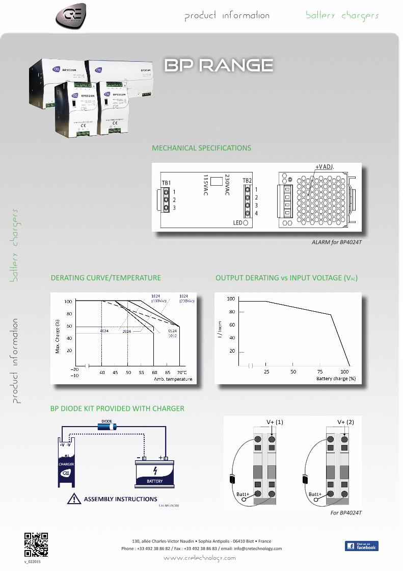
Derati ng may be needed under low input voltage. Please check the derati ng curve for more details.
product information battery chargers product information battery chargers
www.cretechnology.comv_022015
product information battery chargers
BP RANGE
MECHANICAL SPECIFICATIONS
DERATING CURVE/TEMPERATURE
product information battery chargers
130, allée Charles-Victor Naudin • Sophia Anti polis - 06410 Biot • FrancePhone : +33 492 38 86 82 / Fax : +33 492 38 86 83 / email: [email protected]
www.cretechnology.com
OUTPUT DERATING vs INPUT VOLTAGE (VAC)
v_022015
BP DIODE KIT PROVIDED WITH CHARGER
For BP4024T
ALARM for BP4024T