bpa series capacitors - washington state university capacitor purpose •increase transfer...
TRANSCRIPT

BPA Series Capacitors
Purpose, Design, Application & Performance Presented By Mike Hulse

Series Capacitor Purpose
•Increase Transfer Capability –In lieu of constructing a new line and –At a significantly lower cost
•Improves Steady State & Transient Stability –By reducing the lines inductive reactance and –Transmission phase angle
•Reduces System Losses –By reducing sub-transmission power flow
•Improves Load Division Between Circuits –By balancing the impedance of parallel circuits
•Optimize Power Transfer –Adjusting impedance/line thermal capability relationship

Types Of Reactive Power Compensation
Series Compensation •Cost is much lower than building a new transmission circuit •Improved stability by reducing the transmission phase angle •Reduced line inductive reactance •Reduced system losses •Provides desired load division between circuits. •Increases short circuit currents •Increases line-to-ground voltages adjacent to bank •Distance relays my trip for external faults - overreach •Can create or amplify generator sub-synchronous resonance
Source Line Load
L RL1 L2 L3
Substation
SeriesCapacitor

Types Of Reactive Power Compensation
Shunt Capacitors •Provides power factor correction •Improves power system stability with high-speed switching. •Increases the bus voltage when inserted •Act as a surge protective device for impulses
•Little impact on short circuit currents but does contribute an out rush component •Voltage can be high after load rejection
Source Line Load
LL1 L2 L3
ShuntCapacitor

Types Of Reactive Power Compensation
Shunt Reactor •Controls operating voltages by absorbing charging current from lightly loaded lines •Avoids the security and stability impacts of removing lines from service •Improves power system stability with high-speed switching. •Voltage is low after load rejection
Source Line Load
L RL1 L2 L3
Substation
ShuntReactor

Types Of Reactive Power Compensation
Static VAR Compensator (SVC) •Stabilizes bus voltage •Provides dynamic control of reactive power flow •Increases transmission capacity •Improves power system stability, power quality and damping of SSR. •Expensive but effective
Source Line Load
L RL1 L2 L3
Filte
rs
SVC

Types Of Reactive Power Compensation
Thyristor Controlled Series Capacitor (TCSC) •Provides dynamic control of reactive compensation •Improves system stability •Damps power system swings. •Reduces system loses •Controls SSR
Source Line Load
L RL1 L2 L3
Substation
TCSC

Series Capacitor Design Major Bank Components
•Capacitors –Individual fuseless, external or internal fused units in racks
•Metal Oxide Varistor –Non-linear resistor elements in porcelain or non-ceramic housings
•Bypass Gap (Optional Depending on Bank Location and MOV Costs)
– Triggered and/or self-triggered electrodes in an enclosure
•Current Limiting Reactor –Air core multiple package fiberglass epoxy reinforced inductor
•Damping Resistor (Need depends on damping requirements)
–Suitable housed linear and non-linear resistor elements
•Bypass Breaker –SF6 insulated single pressure puffer breaker
•Control & Protection System –Platform transducers, fiber optic communication & ground controls

Series Capacitor Equipment Fuseless Capacitor Units, Racked and Wired
Bushing
Discharge Resistor Element
Crimp Connection
Unit

Series Capacitor Equipment Metal Oxide Varistor

Series Capacitor Equipment Current Limiting Reactor

Series Capacitor Equipment Triggered Air Gap (TAG)

Series Capacitor Equipment • MOV monitoring, high voltage injector & TAG energy storage capacitors

Series Capacitor Equipment Damping Circuit

Series Capacitor Equipment Cogenel FX-12 Bypass Breaker

Series Capacitor Equipment • Platform Fiber Optic Interface & Fiber Optic Columns

Series Capacitor Equipment • Controls and Station Entrance Racks
Example screens show the events, alarms, platform quantities and waveforms
Outside to inside interface rack

Theory of Operation
• During normal operation line current flows through the capacitors via the isolating motor operating disconnects (MOD).
• The voltage across the bank is proportional to the line current through the bank.
• Xc of the bank compensates for a portion of the Xl of the line. Reducing the effective line impedance.
Capacitors MOD
MOD

Theory of Operation • When a fault occurs adjacent to the bank the voltage across the
capacitor increases to a point that damage would occur if the capacitor was unprotected.
• As the voltage across the metal oxide varistor (MOV) increases a portion of the bank current is transferred to the MOV controlling the voltage across the capacitor to the varistor protective level.
• For faults external to the compensated line the varistor would absorb the energy without any further protective action
Fault on the Line
Volta
ge
Current
Normal Operation
Swings & External Faults
Internal Faults
MOV Characteristic

Theory of Operation • For internal faults the protection system monitors MOV current and
energy and triggers the gap to bypass if either exceeds their respective thresholds.
• If the gap is triggered the bank current then passes through a large air core reactor which limits the capacitor discharge to an acceptable level.
• To increase damping, beyond that provided by the reactor, a separate damping circuit can be used used.
• Once the gap is triggered, the gap must be cleared by either the line breaker, when it clears the fault, or the closure of the bypass breaker.
Reactor
Damping Resistor
Triggered Gap
Bypass Breaker

Theory of Operation • When the line breaker clears the fault and the gap current, the bank
resumes normal operation when the breakers reclose the line • Utilities may elect to single phase close the faulted phase bypass
breaker, to control MOV duty, and then opens the breaker after the line is high speed reclosed.
• If the gap arcing persists then the protection three phase closes and locks out the bypass breaker (right picture)

Theory of Operation • Operations can then elect to autoisolate the facility which
automatically confirms the bypass breaker is closed, closes the bypass disconnects and opens the isolating disconnects.
• Once the bank is isolated, from the power system, it can then be grounded, MOD ground blades and portable protective grounds are used, and then safely inspected
• The bank capacitors and those in the gap circuit must be individually grounded before they are physically contacted
Bypass Disconnect
Isolating Disconnect

Equipment Design
• Capacitor Bank Ratings (provided by System Planners) – Capacitive reactance in ohms (XC)
• The XC is typically 25-50% of the compensated lines positive sequence impedance.
– Continuous current rating in Amps (IC) • The ratings selected are based on a combination of the max. stable transfer
capability, the line thermal capability and current sharing between lines. System power flow and transient stability studies.
• Mvars (reactive power ratings) is calculated using the above quantities:
MVARS = 3IC2XC = 3x4000^2x19 = 912 Mvars
• 1 Per Unit (pu) voltage can also be calculated:
VC = ICXC = 4000x19 = 76 kVrms or 107.5 kVpeak
Example is based on Schultz Design

Equipment Design
• Capacitor Unit (Can) Design and Rating – The design is typically developed by the manufacturer – The type of capacitor (external fused, internal fused or fuseless) is
dependent on the voltage across the bank, the bank rated current, unit protection and to a lessor extent utility preference
– Utility specification can influence the size of the unit by specifying or limiting the:
• Enclosed Kvars (limit replacement cost for a unit failure) • Weight (per can for maintenance considerations)
– Considerations affecting a decision to use fuseless units: • Reliability improvement (without fuse related problems) • Protection improvement (element failure produces lower stress increase
compared to a fuse operation) • Lower Losses (fuse element resistance eliminated)
– At Schultz the following unit ratings were specified: • 8.44 kV, 422.2 kVARS and the unit weighed 135 lbs

Equipment Design
• Capacitor Unit Capabilities – As the figure indicates each capacitor
unit has a range of capabilities depending on the duration of the overvoltage.
– The unit design (size, weight & kvars) is directly affected by the specified 30 min rating, the 10 sec system swing current and the MOV protective level.
• Unit Design – Where the supplied data differs from the above the manufacturer
will often adjust the following to insure a survivable product: • Film thickness affecting the Volts/Mil stress • Roll voltage affecting the capacitor unit voltage rating
– These adjustments may also affect the capacitor kVAR, size, weight, and bushing voltage ratings

Equipment Design
• Metal Oxide Varistor (MOV) – The design is based on a combination utility input and the final design developed
by the manufacturer. – Typically utilities indicate:
• Bank reactance • Rated current • 30 min rating • 10 sec system swing current • Fault current (internal & external single phase and three phase faults) • Future ratings (with current and/or ohmic changes)
– The manufacturer studies provide the following MOV attributes • Estimated varistor V-I characteristics • Peak MOV current during internal & external faults via EMTP studies. • Max MOV energy requirements for external and internal fault energy.
(The bank is designed to ride through external faults where the energy and current plus margin is below the current and energy threshold. Above this level it is assumed to be an internal fault where a protective bypass can occur. The bypass can either be gap or breaker depending on the bus fault Mva and cost. The maximum internal fault energy level (after accounting for the time to bypass) is used to size the varistor.)

Equipment Design
• MOV Characteristics – Based on extensive EMTP Studies the following characteristics
were selected for BPA’s Schultz Substations: • Protective Level = 236.5 kVc initial 311.1 kV ultimate @ Coordinating Current = 65 kAc • Mechanical rating = 29.1 MJ initial 46.3 MJ ultimate Worst case internal fault plus reclose prior to gap operation • Thermal rating = 49.1 MJ initial 74.1 MJ ultimate Worst case internal & external fault prior to 30 min rating
– MOV design • Based on the above characteristics the following varistor was
manufactured • Porcelains = 16 plus 2 spares and 1 redundant unit = 19/phase • Each porcelain encloses 4 columns of blocks • To arrive at the ultimate ratings a small additional varistor unit will be
added in series with each of the above porcelains.

Equipment Design
• Gap System – In lieu of significantly increasing the varistor energy rating due to
the operating speed of a bypass breaker (30-40 ms) a gap (100-300 µS) protection system was selected.
– The system consists of the following components: • A triggered gap • Varistor analog & pulser (VAP) system • Varistor monitoring CT’s
– The system is deenergized until (fault) current flows through the varistor and associated CT. Once current begins flowing the VAP monitors and integrates the current. Once either the energy or current protective thresholds are reached an SCR fires and initiates a process which ends with the main gap flashing over.
– The protective energy and current threshold are as follows: • Energy = 19.4 MJ initial 34.9 MJ ultimate • Current = 13.1 kAc initial 15.1 kAc ultimate

Equipment Design • Current Limiting Reactor (CLR) Design
– When either the gap fires or the bypass breaker closes the capacitors would be directly shorted. To avoid damaging the capacitors, gap or bypass breaker by currents approaching 500 kA a CLR is added to the circuit.
– The CLR’s inductive reactance in combination with the self-inductance of the bus is selected to limit the combination of peak capacitor discharge current and fault current to 140 kAc or less or within the close & latch capability of the bypass breaker. However 80 kAp capacitor only discharge was selected due to past experience. There are two procedures to calculate the required inductance: 1. Conservation of energy Energy in the capacitor E=CV2/2 Reactor E=LI2/2 Solving for L yields L=CV2/I2
2. Surge Impedance Method Solving for L yields the same equation as above
– For Schultz the equations yields an inductance of: L=139.6 µF x 236.5 kV2p / 80 kA2p = 1.22 mH Initial L=104.7 µF x 311.1 kV2p / 80 kA2p = 1.58 mH Ultimate
1.64 mH was purchased?
IV
CLz ==

Equipment Design • To avoid replacing the reactor at the time of the upgrade to 25Ω and
meet the 80 kAp requirement 1.64 mH was selected • Current Limiting Reactor (CLR) & Harmonics
– Car must be exercised when selecting the CLR inductance since the parallel combination of the capacitor bank and the reactor + bus inductance can be resonant. To avoid this potential the bank design must be tuned to avoid even or odd harmonic of 60 Hz.
– The following figure shows the circuit and knowing the reactance and capacitance the resonant frequency can be calculated.
LCF
π21
=BusInductance
Reactor
Capacitor Bank
•Assuming a bus inductance of 40 µH, a 1.64 mH reactor and a 139.6 µF capacitor bank yields a resonant frequency of 328 Hz and with a 104.7 µF capacitor 376 Hz. •This process must be repeated for changes in capacitance due to element failures and temperature changes to insure that the resonant frequency is well away from being excited by even and odd system harmonics.

Equipment Design
• Damping Circuit – At the time the gap fires or the bypass breaker closes, the energy
stored in the capacitors is transferred to the magnetic field of the reactor. This transfer back and forth would continue forever in a lossless environment.
– Without damping (resistance around the L-C loop) the capacitor would be overstressed and fail.
– The following illustrates (using ATP) the impact of changing the damping resistance by a factor of ten

Equipment Design
• Damping Circuit Options – Reactor Modifications
• Use of de-qing rings (Stainless steel ring immediately above the air core reactor.) The rings introduce eddy current losses due to the reactor’s magnetic field.
• Modification of the winding arrangement and materials can also increase losses.
– After careful study it was determined to leave the reactor as is. This was due to the:
• Extreme force applied to the de-quing ring during gap operations & faults • Impact on the winding temperature rise.
– Instead a parallel damping circuit was developed. – The circuit consists of linear and non-linear resistors in a porcelain
housing – The damping circuit was located immediately parallel to the CLR.

Equipment Design • Damping Circuit Design
– Sounds simple just add a resistor in parallel with the CLR. Not so due to additional energy that would be absorbed from 60 hZ fault current flowing through the reactor. Two options were available to address this issue:
• Install a gap in series with the linear resistor • Install non-linear resistors in series with the linear resistors
– The linear & non-linear resistor design was selected and was developed to meet the following requirements:
• The ratio of the voltage magnitude is less than 0.90 from one half cycle to the next of the same polarity.
• The I2t will be within the capability of the capacitor. • To minimize losses non-linear resistors will be added in series with the linear
resistor. • The non-linear resistor is sized to eliminate an significant duty to the resistor
element during faults while the bypass breaker is closed. – Computer simulations were conducted to verify the I2t, and identify the
division of energy between the linear and non-linear elements when compared to their capabilities under multiple contingencies.

Equipment Design
• Bypass Breaker – A standard breaker is utilized except for the following:
• The breaker is close priority (close on low pressure and other problems) • Once closed & locked-out the breaker is latched (will not drift open) • The interrupter rating is based on the bank:
– Continuous operating voltage (I*XC) – Varistor protective level (BIL) – Continuous current and 30-min current rating (I) – Capacitor discharge plus fault current (Close and latch)
• The line to ground capability is based on the system voltage – At 500 kV this is typically 1550 or 1800 kV BIL
– The breaker is the primary protective device for the gap system and bypasses the for other problems such as platform faults. The close time for the breaker is as fast as two cycles.
– The breaker may be operated either locally of remotely to bypass or insert the bank.
Insulation Coordination • Purpose is to define the insulation levels for the components that form
the series capacitor bank • Prior to beginning the study the following items are required:
– Location elevation – Capacitive Reactance, Initial & Future – Bank continuous & 30 min current ratings & protective level
• The study will determine the following attributes: – Using the bank nominal current, capacitive reactance and protective level
determine: • Bank continuous operating voltage • Bank protective level voltage • 10-sec wet withstand test level • Creepage distances
– Using the 10-sec wet withstand test level, for continuously energized components, and the protective level, non-continuously energized components, determine:
• Basic lightning impulse insulation level (BIL) • Basic switching impulse insulation level (BSL)

Insulation Coordination
• Bank continuous operating and protective level voltages are: – VB = IBxXC = 4000x25 = 100 kVrms – VPl = VBxPLx√2 = 100x2.2x1.414 = 311.1 kVp
• Calculation of the Wet Withstand Test Level: – IEEE 824 and the supplied specifications provide procedures for
determining the wet 10-sec withstand test level for platform mounted components as follows:
IEEE VPFW ≥1.2x(Altitude Corr. Fac)x VPl/√2 At Schultz VPFW=1.2x1.0x311.1/1.414=264 kVrms
Specification VPFW =3xVB
At Schultz VPFW =3x (4000Ax25Ω)=300kVrms
VPFW is the power frequency wet rms voltage withstand level VPL is the peak voltage magnitude of the protective level VB is the bank continuous operating voltage

Insulation Coordination • Calculation of the BIL & BSL Levels (for continuously energize components)
– As the previous slide indicated using the 3xAC method produced the higher wet withstand voltage, 300 kV. The individual component insulation levels will be a portion of this value depending on the number of capacitors units spanning the structure being insulated.
– For example: Schultz ultimate rating calls for 12 capacitors in series. The same procedure is used for most of the components on the platform. The relationship between wet withstand and BIL/BSL is provided in a number of IEEE/ANSI Standards such as C37.06 and C57.19.01. For system voltages and BILs below 345 kV and 900 kV respectively the BSL is not defined.
2/12 50 150
2/12 50 150
3/12 75 200
3/12 75 200
2/12 50 150
% Wet BIL kVp kVp
Rack Grounds
Platform Ground
Racks

Insulation Coordination
• Calculation of the BIL & BSL Levels (for non-continuously energize components)
– Components not exposed to significant continuous stress are sized based on the bank protective level.
– For example the CLR has an inductive reactance of .618 Ω and the maximum voltage it can be exposed to is the varistor protective level of 311.1 kVp.
• Using the protective level and IEEE 824 calculate the Wet Withstand
Test Level: VPFW=1.2x1.0x311.1/1.414=264 kVrms
– Using C37.06 or C57.19.01 indicates
• The next higher standard wet withstand above 264 is 275 kV • The equivalent BIL is 650 kV • The reactor will therefore be designed for an across BIL of 650 kV

Insulation Coordination • The following figure illustrates the relationship between the 10 sec.
wet withstand test level, equivalent standard BIL level and the number of capacitor units spanning the insulation being specified.
Schultz Wet Withstand & Standard BIL
0
200
400
600
800
0 1 2 3 4 5 6 7 8 9 10 11 12
No. of Capacitors
kV
Wet Withstand Standatd BIL

Insulation Coordination • Calculation of the Insulator Creepage Distances
– Minimum leakage distances are based on IEEE Standards – DM = (Altitude Corr. Fac.) x 1.2 x n x VB x √3 x DS
DM is the min. creepage distance in inches n is the equiv. number of capacitors across the insulation VB is the capacitor unit continuous operating voltage DS is per IEEE 0.59 inch/kV creepage
– For example: • The first rack support insulator spans 2 insulators and each capacitor has an
8.44 kVrms rated voltage DM = 1.0x1.2x2x8.44x1.732x0.59 = 20.7 inches
• The MOV is across the entire bank which initially is 9 capacitors in series and
ultimately 12 in series. Capacitors and MOV will be added in series to upgrade to the ultimate rating
DM = 1.0x1.2x9x8.44x1.732x0.59 = 93.2 inches DM = 1.0x1.2x12x8.44x1.732x0.59 = 124.2 inches
Creepage for initial porcelain is 93.2 in. and the creepage for the additional varistor required to upgrade to 25Ω is the difference between initial and ultimate which is 31 inches

Insulation Coordination • Calculation of the strike (dry arcing) clearances
– These clearances can be calculated using IEC 60071-2 Annex G, IEC 60143 Fig. 4, & IEEE 1313.2 Section 6.2.
– For example the following Table is based on the IEC standard.
10 sec Wet Standard Creepage
n kV rms BIL in m in mm in1 25.3 110 10.3 0.09 3.70 105 4.132 50.6 150 20.7 0.18 6.94 200 7.873 75.9 200 31.0 0.26 10.09 280 11.024 101.2 350 41.4 0.34 13.23 360 14.175 126.5 350 51.7 0.42 16.39 440 17.326 151.8 450 62.1 0.50 19.58 520 20.477 177.1 450 72.4 0.58 22.82 605 23.828 202.4 550 82.7 0.66 26.12 645 25.399 227.7 550 93.1 0.75 29.49 760 29.9210 253 650 103.4 0.84 32.93 845 33.2711 278.3 650 113.8 0.93 36.45 925 36.4212 303.6 750 124.1 1.02 40.06 1020 40.16
Alt. Corr1 K Correction
Std Creep 1 10.59
Annex GIEC 60071-2
Use above 2 Meters
K from 1.25-1.47
IEC 60043Section 6 Fig 4

Insulation Coordination • The following figure illustrates the relationship between the creepage
distance required across the outdoor insulation, the strike distance across air insulated structures and the number of capacitor units spanning the insulation being specified.
Schultz Creepage & Strike
0.020.040.060.080.0
100.0120.0140.0
0 1 2 3 4 5 6 7 8 9 10 11 12
No. of Capacitors
Inch
es
Creepage Air Clearance

Field Testing • BPA has historically performed staged fault test (field tests) on a variety
of equipment such as HVDC converters, TCSC, SVC, breakers and series capacitors facilities.
• The purpose of these tests was to verify the adequacy of the equipment design of this new installation and the interaction with other power system components such as line distance relays. In terms of series capacitors the primary test objectives were: – To establish that the insulation levels of the platform components are
properly coordinated, – To verify that the control and protection system operates properly and
provides the appropriate alarms, annunciation and platform quantities at ground level,
– To verify that, under fault conditions, all the major platform components, within the current carrying path, can withstand duty which can in some cases approach their specified capability,
– To evaluate the proper operation of adjacent line and equipment relaying for various system configurations, and
– To gather data for use in improving electromagnetic transient (EMTP) modeling of similar facilities.

Field Testing • To establish the proper operation of the series capacitor facilities a
number of quantities must be monitored. The following provides a summary of the quantities monitored and equipment used during a recent field test: Quantities Measured
Measurement Devices
MOV & Capacitor Voltage
2 each - 100 kV Haefely RCR dividers (5000:1) in series
Capacitor Currents Upper & Lower
50 micro-ohm shunts
MOV Current
1 milli-ohm shunt
Total Platform Current
50 micro-ohm shunt
Line to Ground Voltage
Substation CVTs (Ratios below with a 10:1 attenuator) A phase – 3611 to 1 B phase – 3596 to 1 C phase – 4500 to 1
Bypass Breaker Current
50 micro-ohm shunt
L-G Fault & Secondary Arc Current
250 micro-ohm shunt
Breaker Close Coil Voltage
10:1 attenuator

Field Testing
V
MOV Current1 m Ohm
Fault Current250 µ Ohm
Capacitor Current50 µ Ohm
Breaker Current50 µ Ohm
Line to GroundVoltage10 to 1
Attenuator
Breaker Close Signal10 to 1 Attenuator
Total Bank Current50 µ Ohm
• The schematic below identifies the shunts, dividers and attenuators that were used during the performance of the test.

Field Testing • Outdoor Test Equipment
Fault Rings
Dividers
Attenuator & Transmitter
Low Voltage Med. Voltage High Voltage Shunt & Transmitter
GOFI

Field Testing • Equipment in Trailer
LeCroy Digitizers Sequencer Oscilloscope
Amplifers Tape Drive Wave Tek DFR Ready to Test

Field Testing • A field test is like a rocket launch, every this has to be perfect before the button is pushed.
During the test everyone has a assignment. From nearest to furthest away the following functions are performed:
– Pushes the button on the sequencer to trigger the GOFI via digital fiber optics – Starts the Digital Fault Recorder (DFR), creates a paper backup recording – Starts the Tape Drive, creates an electronic backup recording at 10 kHz – Enables the LeCroy to high speed record the fault quantities at 200kHz or up to 1 MHz – Out of the picture, using a DEC workstation analyzes faults and creates waveforms

Field Test - Fault Movie

Field Test - Waveforms

Field Test - Capacitor Problems

Field Test - Varistor Problems

Field Test - Gap Problems

Field Test - Reactor Problems


The End

BPA Series Capacitor Banks
Alvey No. 1
Platform
19 ohms 302 MVARS 2300 amps 3450 amps 30-min. MOV 68 MJ/phase w/ 2.2 pu PL MOV & Breaker Protection, Cogenel FX-12 Bypass Siemens Disconnects

BPA Series Capacitor Banks
Sand Springs No. 1 & 3 31.6 Ohms 546 MVARS 2400 amps 3800 amps 30-min. MOV #1 85 MJ/phase w/ 2.3 pu PL #3 103 MJ/phase w/ 2.3 pu PL MOV & Breaker Protection Cogenel FX-12 Bypass Breaker, Siemens Disconnects
Platform

BPA Series Capacitor Banks
Sycan No 1 & 3
No. 1 31.6 ohms 546 MVARS 2400 amps 3800 amps 30-min MOV 76 MJ/phase w/ 2.3 pu PL MOV & Breaker Protection Cogenel FX-12 Bypass Breaker Siemens Disconnects No. 3 21.5 ohms 470 MVARS 2700 amps 4000 amps 30-min. MOV 86.8 MJ/phase w/ 2.2 pu PL MOV & Breaker Protection Cogenel FX-12 Bypass Breaker Siemens Disconnects
Platform

BPA Series Capacitor Banks
Fort Rock No. 1 & 3
Platform
Fort Rock
Normally Closed
21 ohms 363 MVARS 2400 amps 3200 amps 30-min. MOV #1 37 MJ/phase w/ 2.2 pu PL #3 53.9 MJ/phase w/ 2.2 pu PL MOV & Breaker Protection Cogenel FX-12 Bypass Breaker Siemens Disconnects

BPA Series Capacitor Banks
Captain Jack & Malin
Platform
Malin 25 ohms (12.5+12.5)
546.8 MVARS 2700 amps 4100 amps 30-Min. MOV 23.5 MJ/Seg./Phase w/ 2.2 pu PL MOV & Gap Protection Cogenel FX-12 Bypass Breaker Siemens Disconnects
Capt. Jack
18 ohms (9+9) 192 MVARS 2667 amps 4000 MVARS 30-min. MOV 22.5 MJ/Seg./Phase w/ 2.3 pu PL MOV & Gap Protection Cogenel FX-12 Bypass Breaker Southern States Disconnects

BPA Series Capacitor Banks
Slatt
Platform
......
8 ohms (-1.2 to 24 ohms) 202 MVARS 2900 amps 4350 amps 30-min. 5800 kV 10-sec. MOV 2.46 MJ/phase MOV & Thyristor Protection Cogenel FX-12 Bypass Breaker Siemens Disconnects Module Ratings: 1989 μF 3.87 kV .47 mH 12.03 kV Protective Level. Note: 2 segment are shown out of the 6 total.

BPA Series Capacitor Banks
Columbia 1 & 2
Platform
21.3 ohms (Ultimate 19.97 ohms) 575 MVARS (Ultimate 613 MVARS) 3000 amps (Ultimate 3200 amps) 4050 amps 30-min. (Ultimate 4320 amps) 5400 amps 10-Sec (Ultimate 5760 amps) MOV 31 MJ/phase w/ 2.5 pu PL MOV & Gap Protection Cogenel FX-12 Bypass H. K. Porter Disconnects

BPA Series Capacitor Banks
Schultz 1 & 2
Platform
19 ohms (Ultimate 25.33 ohms) 912 MVARS (Ultimate 1216 MVARS) 4000 amps 5400 amps 30-min. 6720 amps 10-Sec (Ultimate 6640 amps) MOV 60.3 MJ/phase w/ 2.2 pu PL (Ultimate 74.1 MJ/phase w/ 2.17 pu PL) MOV & Gap Protection Cogenel FX-12 Bypass Southern States Disconnects
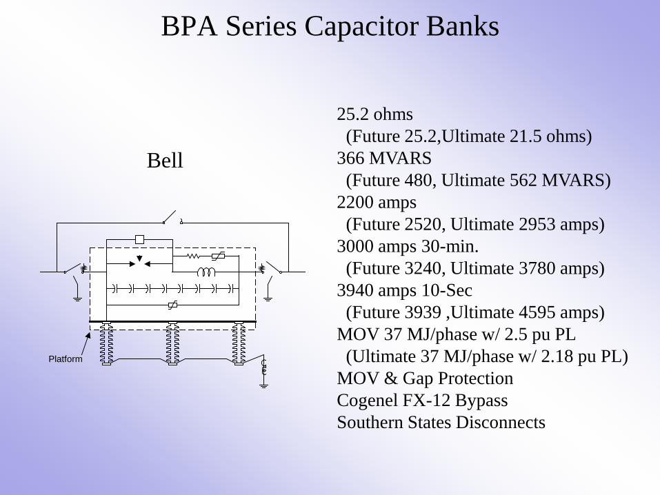
BPA Series Capacitor Banks
Bell
Platform
25.2 ohms (Future 25.2,Ultimate 21.5 ohms) 366 MVARS (Future 480, Ultimate 562 MVARS) 2200 amps (Future 2520, Ultimate 2953 amps) 3000 amps 30-min. (Future 3240, Ultimate 3780 amps) 3940 amps 10-Sec (Future 3939 ,Ultimate 4595 amps) MOV 37 MJ/phase w/ 2.5 pu PL (Ultimate 37 MJ/phase w/ 2.18 pu PL) MOV & Gap Protection Cogenel FX-12 Bypass Southern States Disconnects

BPA Series Capacitor Banks
Dworshak 28 ohms (Future 29.08, Ultimate 24.39 ohms) 336 MVARS (Future 503, Ultimate 609 MVARS) 2000 amps (Future 2400, Ultimate 2885 amps) 2700 amps 30-min. (Future 3000, Ultimate 3577 amps) 3600 amps 10-Sec (Future 3793 ,Ultimate 4523 amps) MOV 42 MJ/phase w/ 2.5 pu PL (Future 42 MJ/phase w/ 2.01 pu PL) (Ultimate 42 MJ/phase w/ 1.99 pu PL) MOV & Gap Protection Cogenel FX-12 Bypass Southern States Disconnects
Platform

BPA Series Capacitor Banks
Garrison (Taft Side 1 & 2) (Being Rebuilt)
Platform
28.9 ohms (Future 28.58, Ultimate 24.76 ohms) 347 MVARS (Future 494, Ultimate 592 MVARS) 2000 amps (Future 2400, Ultimate 2823 amps) 2700 amps 30-min. (Future 3000, Ultimate 3500 amps) 3600 amps 10-Sec (Future 3701 ,Ultimate 4268 amps) MOV 19 MJ/phase w/ 2.4 pu PL (Future 19 MJ/Phase w/ 2.02 pu PL) (Ultimate 19 MJ/phase w/ 1.99 pu PL) MOV & Gap Protection Cogenel FX-12 Bypass H. K. Porter Disconnects

BPA Series Capacitor Banks
Garrison (Broadview Side 1 & 2) (Being Rebuilt)
Platform
39.5 ohms (Future 39.5, Ultimate 33.85 ohms) 474 MVARS (Future 683, Ultimate 796 MVARS) 2000 amps (Future 2400, Ultimate 2800 amps) 2700 amps 30-min. (Future 2976, Ultimate 3472 amps) 3600 amps 10-Sec (Future 3660 ,Ultimate 4270 amps) MOV 17 MJ/phase w/ 2.4 pu PL (Future 17 MJ/phase w/ 2.0 pu PL) (Ultimate 17 MJ/phase w/ 2.0 pu PL), MOV & Gap Protection Cogenel FX-12 Bypass H. K. Porter Disconnects