bracing - branz build · pdf file2 — build — bracing for over 30 years, kiwi...
TRANSCRIPT

Bracing
WWW.BRANZ.CO.NZ
Supplement

2 — Build — Bracing
For over 30 years, Kiwi building professionals like you have been relying on GIB® bracing systems. Designed and tested in New Zealand for local conditions, they meet and exceed New Zealand’s stringent building codes and are backed by local technical support. So you can build with confidence and complete peace of mind.*
GIB EzyBrace® Systems software and technical literature is available at gib.co.nz/ezybrace. Or for technical support call the GIB® Helpline on 0800 100 442.
YOU’RE PROTECTED WITH GIB EZYBRACE® SYSTEMS.
GIB® is a registered trademark. *Provided they are used, stored, installed and maintained strictly in accordance with current Winstone Wallboards technical information.
DOWNLOAD THE GIB® APP NOWGo to your App Store or Google Play Store.
J1/W
WB
0020
/BLD
WWB0020 LBTS Trust BLD ad.indd 1 21/02/14 9:40 AM

Build — Bracing— 1
For over 30 years, Kiwi building professionals like you have been relying on GIB® bracing systems. Designed and tested in New Zealand for local conditions, they meet and exceed New Zealand’s stringent building codes and are backed by local technical support. So you can build with confidence and complete peace of mind.*
GIB EzyBrace® Systems software and technical literature is available at gib.co.nz/ezybrace. Or for technical support call the GIB® Helpline on 0800 100 442.
YOU’RE PROTECTED WITH GIB EZYBRACE® SYSTEMS.
GIB® is a registered trademark. *Provided they are used, stored, installed and maintained strictly in accordance with current Winstone Wallboards technical information.
DOWNLOAD THE GIB® APP NOWGo to your App Store or Google Play Store.
J1/W
WB
0020
/BLD
WWB0020 LBTS Trust BLD ad.indd 1 21/02/14 9:40 AM
Bracing
Supplement
www.branz.co.nzISSN: 0110 4381
3 1. Introduction
4 2. Bracing using NZS 3604:2011
8 3. Wind zones and NZS 3604
12 4. Topographic zones
14 5. Subfloor bracing
186. Bracing for suspended floors
19 7. Bracing for steps in floors and ceilings
21 8. Wall bracing
269. Walls at angles to bracing lines
2710. Roof bracing
3011. Bracing ratings
© BRANZ Ltd, April 2014

2 — Build — Bracing
Build — Bracing— 3
1
The information contained within this publication is of a general nature only. All organisations involved in the preparation of this document do not accept any
responsibility or liability for any direct, indirect, incidental, consequential, special, exemplary or punitive damage, for any loss of profit income or any intangible
losses, or any claims, costs, expenses, or damage, whether in contract, tort (including negligence), equity or otherwise, arising directly or indirectly from, or
connected with, your use of this publication, or your reliance on information contained in this publication.
Any standard referred to within this publication can be purchased from Standards New Zealand by phoning 0800 782 632 or by visiting www.standards.co.nz.
Please note, the BRANZ books and bulletins mentioned in this publication may be withdrawn at any time. For more information and an up-to-date list, visit
BRANZ Shop online at www.branz.co.nz or phone BRANZ 0800 80 80 85, press 2.
Disclaimer
BRACING OF A TIMBER-FRAMED BUILDING is
required to resist horizontal wind and earth-
quake loads. The bracing demand to resist wind
is expressed in bracing units (BUs) per lineal
metre and bracing units per square metre for
earthquakes.
This compilation of articles from Build
magazine looks at the bracing requirements for
buildings built in accordance with NZS 3604:2011
Timber-framed buildings.
It starts by looking at what information is
needed to start calculating bracing and to
determine what needs to be provided for bracing
calculations. It then works its way through
the bracing requirements for various parts
of the building, from subfloor to wall to roof,
using examples to illustrate how to apply NZS
3604:2011.
PROVIDING SUFFICIENT BRACING CAPACITY FOR WIND AND EARTHQUAKE IS AN INTEGRAL PART OF THE DESIGN PROCESS.
Introduction

4 — Build — Bracing
2
Bracing for wind along the ridge.
H for subfloor (Table 5.5)
10 m max. for NZS 3604 scope
average ground height
lowest ground point
lower floor level
upper floor level
H for top or single storey (Table 5.6)
H for lower of 2 storeys (Table 5.7)
h = height of roof above eaves
wind direction along ridge
W where roof pitch is greater than 25°
W where roof pitch is less than 25°
bracing elements in line with ridge and wind direction
How to work out H and h.Figure 1
Figure 2
IN PREPARATION FOR WORKING OUT BRACING REQUIREMENTS FOR A BUILDING, SOME INFORMATION NEEDS TO BE COLLECTED.
Bracing using NZS 3604:2011
BEFORE STARTING BRACING CALCUALTIONS, the
designer will need to collect the following infor-
mation for the specific building.
NZS 3604:2011Is the building being considered within the scope
of NZS 3604:2011? For this, it must be no more
than 2-storeys and a maximum height of 10 m
from the lowest ground level to the uppermost
portion of the roof.
Designs within the scope of NZS 3604:2011
must provide bracing capacity that exceeds the
higher of the minimum requirements in NZS
3604:2011 for:
○ wind demand – Tables 5.5, 5.6 and 5.7
○ earthquake demand – Tables 5.8, 5.9 and 5.10.
Wind zoneSome territorial authorities have maps with wind
zones. Otherwise, see NZS 3604:2011 5.2.1 to
work out the wind zone. Steps to do this are also
on pages 8–10, or consult an engineer.
When the structure is situated in a lee zone,
also see the increased requirements in the notes
at the bottom of Table 5.4.
Earthquake zoneEstablish the earthquake zone from NZS
3604:2011 Figure 5.4. For Christchurch, refer to
Building Code clause B1 3.1.2.
Floor plan areaWhat is the floor plan area in square metres at
the level being considered? This is needed for
earthquake demand calculations – the total floor
Build — Bracing— 5
The type of soil class is needed to calculate the
bracing units required to resist earthquakes. For
multiplication factors for soil types see:
○ Table 5.8 – single storey on subfloor framing
for various wall and roof claddings
○ Table 5.9 – 2-storey on subfloor framing for
various wall and roof claddings
○ Table 5.10 – single and 2-storey on slab for
various wall and roof claddings.
Building shape What is the building shape? NZS 3604:2011
clause 5.1.5 sets out the requirements for build-
ings that have:
○ wings or blocks that extend more than 6 m
from the building – these need su¡cient
bracing individually
○ split-level floors – each level to have su¡cient
bracing individually and to have wall and
subfloor bracing at the position of the
discontinuity
○ floors or ceilings with a step more than
100 mm in the finished levels – a bracing line
is required in the storey below at the location
of the discontinuity, and the bracing element
in the storey below must run continuously
from the storey below to the underside of the
upper levels.
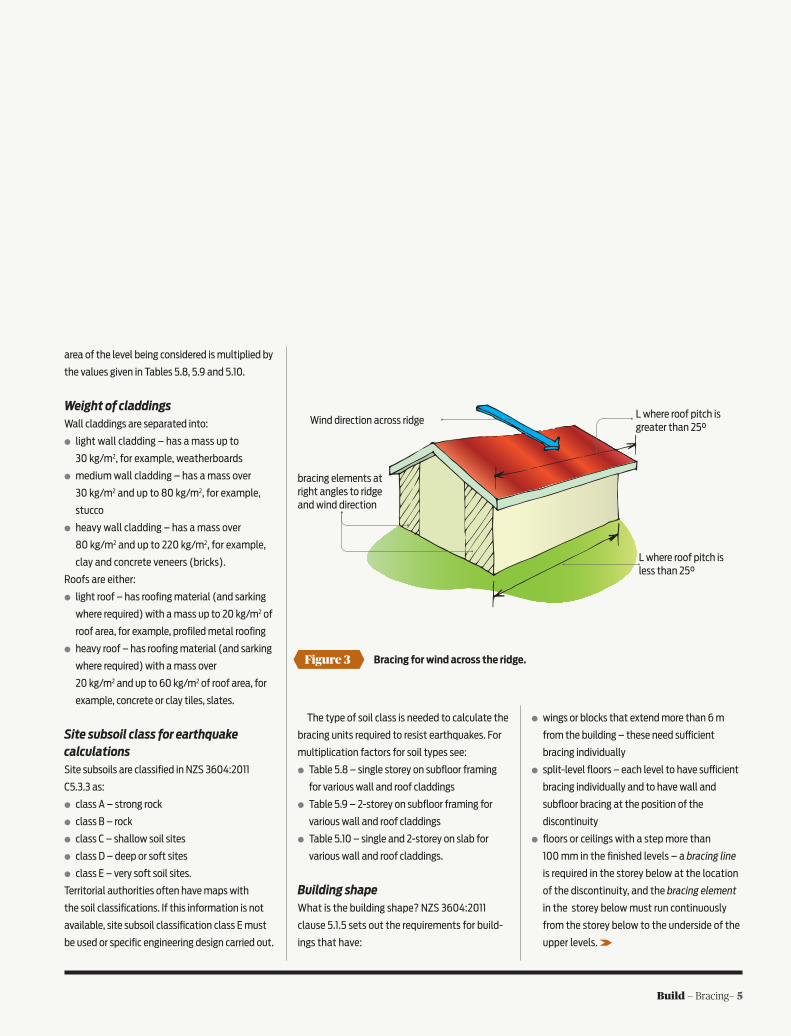
bracing elements at right angles to ridge and wind direction
Wind direction across ridgeL where roof pitch is greater than 25°
L where roof pitch is less than 25°
Bracing for wind across the ridge.Figure 3
area of the level being considered is multiplied by
the values given in Tables 5.8, 5.9 and 5.10.
Weight of claddingsWall claddings are separated into:
○ light wall cladding – has a mass up to
30 kg/m2, for example, weatherboards
○ medium wall cladding – has a mass over
30 kg/m2 and up to 80 kg/m2, for example,
stucco
○ heavy wall cladding – has a mass over
80 kg/m2 and up to 220 kg/m2, for example,
clay and concrete veneers (bricks).
Roofs are either:
○ light roof – has roofing material (and sarking
where required) with a mass up to 20 kg/m2 of
roof area, for example, profiled metal roofing
○ heavy roof – has roofing material (and sarking
where required) with a mass over
20 kg/m2 and up to 60 kg/m2 of roof area, for
example, concrete or clay tiles, slates.
Site subsoil class for earthquake calculationsSite subsoils are classified in NZS 3604:2011
C5.3.3 as:
○ class A – strong rock
○ class B – rock
○ class C – shallow soil sites
○ class D – deep or soft sites
○ class E – very soft soil sites.
Territorial authorities often have maps with
the soil classifications. If this information is not
available, site subsoil classification class E must
be used or specific engineering design carried out.

6 — Build — Bracing
Dimensions for mono-pitched roofs.
L or W where roof pitch is less than 25°
L or W where roof pitch is greater than 25°
H
h
W
WL
L
the higher of wind along or across ridge
Figure 4
™ and ® denote a trademark or registered mark owned by James Hardie Technology Ltd © Copyright 2014 James Hardie
BRACEYOURSELF.
HardieBrace™ is James Hardie’s new
bracing calculator, which allows designers
to quickly and accurately calculate
structural bracing demands. To try
HardieBrace™ for free, register at
accel.co.nz or call 0800 808 868 today.
JAM0001_Bracing Design BRANZ Ad_AW.indd 1 28/02/14 4:33 PM
Heights of buildingsUse NZS 3604:2011 Figure 5.3 to establish heights
H and h for bracing applications. H may have
di£erent values for di£erent sections of the same
building (see Figure 1), for example:
○ for subfloor bracing requirements, H = the
average height of finished ground level to the
roof apex (use Table 5.5)
○ for a single or upper floor level, H = single or
upper finished floor level to roof apex (use
Table 5.6)
○ for lower finished floor level, H = lower finished
floor level to roof apex (use Table 5.7)
○ for roof height above the eaves, h = apex of
roof to bottom of eaves (use Table 5.5, 5.6
and 5.7).
Roof types What is the type(s) of roof? NZS 3604:2011
Figure 5.3 shows where bracing needs to be in
relation in wind direction.
Gable roof – wind along ridge
Bracing elements to resist wind are placed in line
with the ridge and wind direction (see Figure 2).
To calculate the required bracing units along
the building, multiply W by the value in the
right-hand ‘Along’ column in NZS 3604:2011
Table 5.5 (subfloor), 5.6 (upper or single-level
walls) or 5.7 (lower of 2 storeys). These tables
are for high wind zone. In other zones, use the
multiplying factor for the relevant wind zone
found at the bottom of the relevant table.
Gable roof – wind across ridge
Bracing elements for wind across the building
are positioned in line with the wind direction
and at right angles to the ridge line (see Figure 3).
To calculate the bracing units required in the
across direction, multiply L by the value in the
‘Across’ column in NZS 3604:2011 Table 5.5
(subfloor), 5.6 (upper or single level walls) or
5.7 (lower of 2 storeys). As above, if not in a high
wind zone use the relevant wind zone multiplying
factor at the bottom of the table.
Hip roofs
Use ‘Across’ values in NZS 3604:2011 Tables 5.5,
5.6 and 5.7 for along and across directions.
Mono-pitched roofs
Roof height above the eaves is taken as the
di£erence between lower eaves height and roof
apex (see Figure 4).
When roof pitch is:
○ 25° or less, use wall width or length
○ greater than 25°, use roof dimensions.
To calculate the bracing units required, use the
higher value of the along and across calculations
in NZS 3604:2011 Tables 5.5, 5.6 and 5.7 is used.
Limitations on bracing allocationBased on hold-down capabilities, there are some
maximum ratings for bracing elements that can
be used in calculations. The maximum for:
○ timber floors is 120 bracing units/metre
○ concrete floors is 150 bracing units/metre.
The bracing design should evenly distribute the
bracing throughout the building rather than con-
centrating them in ends of buildings or outside
walls.
Extra B/Us for part storey and chimneysWhere there is a part storey contained in a:
○ timber-framed basement, regard the building
as two buildings for demand calculations — one
2-storey (has basement underneath) and one
single-storey – and use the appropriate tables
○ roof space, the bracing demand values in
Tables 5.8, 5.9 and 5.10 (earthquake) must be
increased by 4 bracing units/square metre.
Where a masonry or concrete chimney is
dependent on the building structure for lateral
support, additional demand is also required –
see B1/AS3.
Several suppliers of wall bracing
systems provide free on-line calculators to work
out bracing requirements.
Note

™ and ® denote a trademark or registered mark owned by James Hardie Technology Ltd © Copyright 2014 James Hardie
BRACEYOURSELF.
HardieBrace™ is James Hardie’s new
bracing calculator, which allows designers
to quickly and accurately calculate
structural bracing demands. To try
HardieBrace™ for free, register at
accel.co.nz or call 0800 808 868 today.
JAM
0001
JAM0001_Bracing Design BRANZ Ad_AW.indd 1 28/02/14 4:33 PM
8 — Build — Bracing
Wind zones and NZS 3604
FOUNDATIONS AND WALLS of timber-framed
buildings must be braced to resist the horizontal
forces from earthquakes and wind. When design-
ing bracing, calculations of both earthquake and
wind forces (called bracing demand) must be
made and the building constructed to withstand
the stronger of the calculated forces (called
bracing capacity). Although New Zealand lies in a
region of high seismic activity, it is often the hor-
izontal forces imposed by wind that determine
the bracing requirement.
The shape, size and level (whether basement,
ground or first floor) of the building, as well as
its actual location, all a£ect the wind bracing
demand, but in order to calculate the bracing
demand, the wind zone, rated as low (L) to extra
high (EH) wind speed, must first be determined.
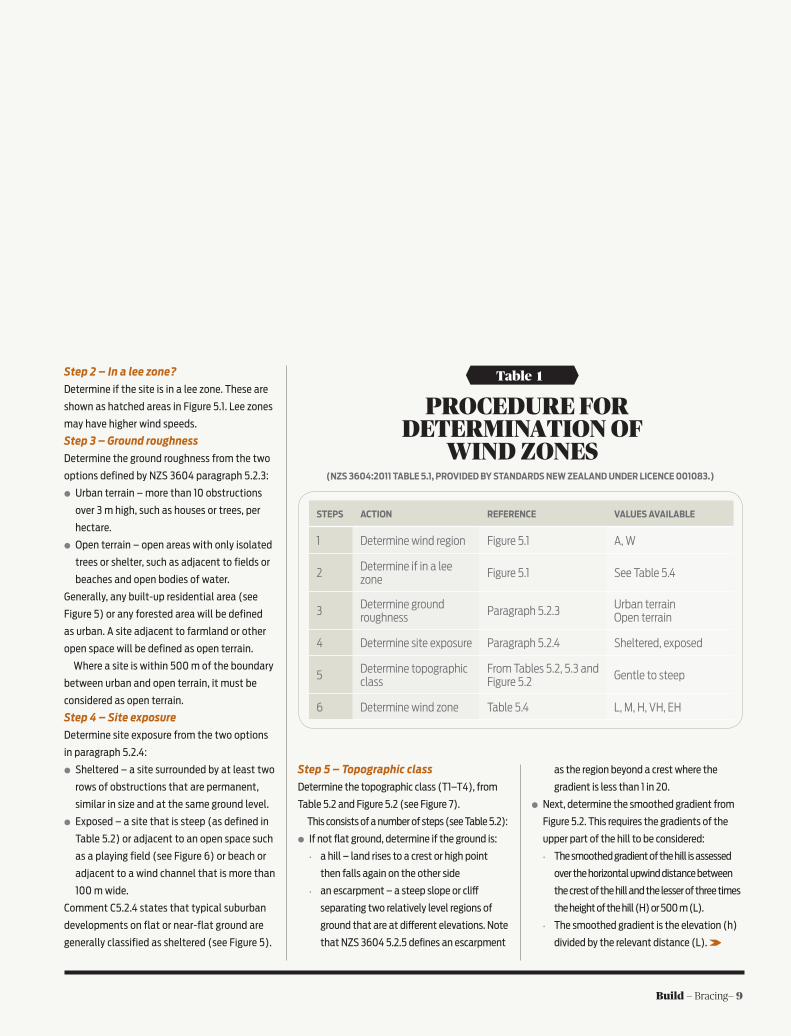
Six steps to determine wind zoneA means of determining the wind zone for a
specific location is in NZS 3604:2011 Table 5.1 (see
Table 1). This describes a six-step process.
Step 1 – Wind region
The first step is to identify the wind region for the
building from NZS 3604:2011 Figure 5.1. This map
divides the country into two wind regions – A and
W – based on wind speed data from the New
Zealand MetService.
The regions are too general, however, as land
formations can modify and create significant
localised variations to wind speeds. For example,
wind speed will increase as it passes over and
between hills and decrease when passing over
rough ground.
OFTEN WIND DETERMINES THE BRACING REQUIREMENT FOR TIMBER-FRAMED BUILDINGS. WE WALK THROUGH HOW TO FIND THE CORRECT WIND ZONE FOR A SITE USING NZS 3604:2011.
3
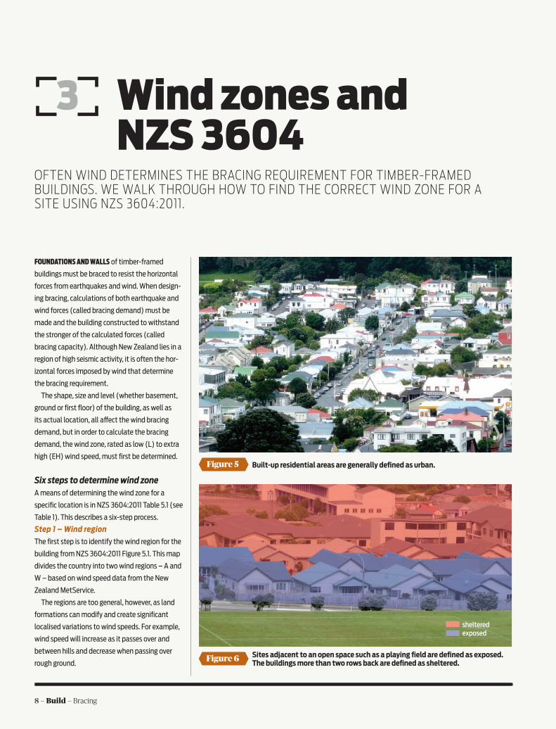
Sites adjacent to an open space such as a playing field are defined as exposed. The buildings more than two rows back are defined as sheltered.
Built-up residential areas are generally defined as urban.
shelteredexposed
Figure 6
Figure 5
Build — Bracing— 9
Wind zones and NZS 3604
STEPS ACTION REFERENCE VALUES AVAILABLE
1 Determine wind region Figure 5.1 A, W
2 Determine if in a lee zone Figure 5.1 See Table 5.4
3 Determine ground roughness Paragraph 5.2.3 Urban terrain
Open terrain
4 Determine site exposure Paragraph 5.2.4 Sheltered, exposed
5 Determine topographic class
From Tables 5.2, 5.3 and Figure 5.2 Gentle to steep
6 Determine wind zone Table 5.4 L, M, H, VH, EH
Table 1
PROCEDURE FOR DETERMINATION OF
WIND ZONES(NZS 3604:2011 TABLE 5.1, PROVIDED BY STANDARDS NEW ZEALAND UNDER LICENCE 001083.)
Step 2 – In a lee zone?
Determine if the site is in a lee zone. These are
shown as hatched areas in Figure 5.1. Lee zones
may have higher wind speeds.
Step 3 – Ground roughness
Determine the ground roughness from the two
options defined by NZS 3604 paragraph 5.2.3:
○ Urban terrain – more than 10 obstructions
over 3 m high, such as houses or trees, per
hectare.
○ Open terrain – open areas with only isolated
trees or shelter, such as adjacent to fields or
beaches and open bodies of water.
Generally, any built-up residential area (see
Figure 5) or any forested area will be defined
as urban. A site adjacent to farmland or other
open space will be defined as open terrain.
Where a site is within 500 m of the boundary
between urban and open terrain, it must be
considered as open terrain.
Step 4 – Site exposure
Determine site exposure from the two options
in paragraph 5.2.4:
○ Sheltered – a site surrounded by at least two
rows of obstructions that are permanent,
similar in size and at the same ground level.
○ Exposed – a site that is steep (as defined in
Table 5.2) or adjacent to an open space such
as a playing field (see Figure 6) or beach or
adjacent to a wind channel that is more than
100 m wide.
Comment C5.2.4 states that typical suburban
developments on flat or near-flat ground are
generally classified as sheltered (see Figure 5).
Step 5 – Topographic class
Determine the topographic class (T1–T4), from
Table 5.2 and Figure 5.2 (see Figure 7).
This consists of a number of steps (see Table 5.2):
○ If not flat ground, determine if the ground is:
• a hill – land rises to a crest or high point
then falls again on the other side
• an escarpment – a steep slope or cli£
separating two relatively level regions of
ground that are at di£erent elevations. Note
that NZS 3604 5.2.5 defines an escarpment
as the region beyond a crest where the
gradient is less than 1 in 20.
○ Next, determine the smoothed gradient from
Figure 5.2. This requires the gradients of the
upper part of the hill to be considered:
• The smoothed gradient of the hill is assessed
over the horizontal upwind distance between
the crest of the hill and the lesser of three times
the height of the hill (H) or 500 m (L).
• The smoothed gradient is the elevation (h)
divided by the relevant distance (L).
10 — Build — Bracing
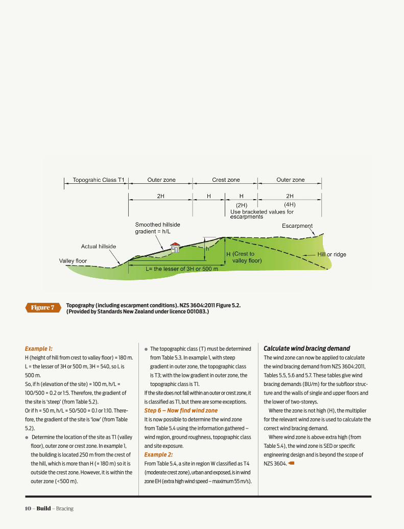
Topography (including escarpment conditions). NZS 3604:2011 Figure 5.2. (Provided by Standards New Zealand under licence 001083.)
Figure 7
Example 1:
H (height of hill from crest to valley floor) = 180 m.
L = the lesser of 3H or 500 m, 3H = 540, so L is
500 m.
So, if h (elevation of the site) = 100 m, h/L =
100/500 = 0.2 or 1:5. Therefore, the gradient of
the site is ‘steep’ (from Table 5.2).
Or if h = 50 m, h/L = 50/500 = 0.1 or 1:10. There-
fore, the gradient of the site is ‘low’ (from Table
5.2).
○ Determine the location of the site as T1 (valley
floor), outer zone or crest zone. In example 1,
the building is located 250 m from the crest of
the hill, which is more than H (= 180 m) so it is
outside the crest zone. However, it is within the
outer zone (<500 m).
○ The topographic class (T) must be determined
from Table 5.3. In example 1, with steep
gradient in outer zone, the topographic class
is T3; with the low gradient in outer zone, the
topographic class is T1.
If the site does not fall within an outer or crest zone, it
is classified as T1, but there are some exceptions.
Step 6 – Now find wind zone
It is now possible to determine the wind zone
from Table 5.4 using the information gathered –
wind region, ground roughness, topographic class
and site exposure.
Example 2:
From Table 5.4, a site in region W classified as T4
(moderate crest zone), urban and exposed, is in wind
zone EH (extra high wind speed – maximum 55 m/s).
Calculate wind bracing demandThe wind zone can now be applied to calculate
the wind bracing demand from NZS 3604:2011,
Tables 5.5, 5.6 and 5.7. These tables give wind
bracing demands (BU/m) for the subfloor struc-
ture and the walls of single and upper floors and
the lower of two-storeys.
Where the zone is not high (H), the multiplier
for the relevant wind zone is used to calculate the
correct wind bracing demand.
Where wind zone is above extra high (from
Table 5.4), the wind zone is SED or specific
engineering design and is beyond the scope of
NZS 3604.
Appraisal No.831 [2013]

Appraisal No.831 [2013]
12 — Build — Bracing
WE ALL KNOW from experience that hilltops (and
other exposed locations) have higher wind speeds
than the valley floor, and the topographic classes
T1 to T4 are a measure of just how much higher.
Start with shape of groundThe first step is to stand back and get an
overall picture of the shape of the ground
surrounding the site. Don’t get into too much
detail. This is big picture stuff and is best done
by a site visit.
Most of New Zealand’s hill country is ‘spur/
gully’ formation where the land drops away on
both sides of a hilltop, ridge or spur. This is a ‘hill
shape’ in NZS 3604-speak.
However, around the coasts or beside large
river valleys, there are often ‘escarpments’
where the water has cut away one side of the
hill and the other side is relatively flat. Note that
if the ground comprises undulations of less than
10 m (height of a 3-storey house) or is flatter
than 1:20, the topographic class is T1.
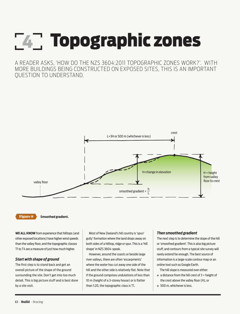
Then smoothed gradientThe next step is to determine the slope of the hill
or ‘smoothed gradient’. This is also big picture
stu£, and contours from a typical site survey will
rarely extend far enough. The best source of
information is a large-scale contour map or an
online tool such as Google Earth.
The hill slope is measured over either:
○ a distance from the hill crest of 3 × height of
the crest above the valley floor (H), or
○ 500 m, whichever is less.
4
Figure 8
hLsmoothed gradient =
Smoothed gradient.
valley floor
L=3H or 500 m (whichever is less)
H = height from valley floor to crest
h=change in elevation
crest
A READER ASKS, ‘HOW DO THE NZS 3604:2011 TOPOGRAPHIC ZONES WORK?’. WITH MORE BUILDINGS BEING CONSTRUCTED ON EXPOSED SITES, THIS IS AN IMPORTANT QUESTION TO UNDERSTAND.
Topographic zones

Build — Bracing— 13
Determining topographic zone in steep hillside.Figure 9
In this example, smoothed gradient should be:
100/200 = 0.5 = steep NOT 50/300 = 0.17 = moderate
valley floor
crest
50 m
3H=300 m
L=200 m
H=100 mh
H
Hill shape
H H2H 2H
T1
T1
T1
T1
crest
crest zoneouter zoneouter zone
Escarpment
4H
crest
outer zone
H2H
crest zoneouter zone
H
2H
Figure 10
Figure 11
Figure 5.2 of NZS 3604:2011 Timber-framed build-
ings is misleading here, and an alternative is given
in Figure 8.
The smoothed gradient is h/L. Where the
distance L extends from the crest up the next hill,
as can sometimes happen in steeper country (see
Figure 9), take L as the distance to the valley floor.
Position of buildingNext consider the position of the building site in
relation to the crest of the hill (or escarpment):
○ If it is within distance H (or 2H downwind for
an escarpment), it is in the ‘crest zone’ where
wind acceleration is a maximum.
○ If it is between 1H and 3H from the crest
(or between 2H and 6H downwind for an
escarpment), it is within the ‘outer zone’.
○ If it is more than 3H (or 6H for an escarpment),
it is T1 because wind acceleration is not
significant.
See Figures 10 and 11.
Note that row 4 in NZS 3604 Table 5.2 is
irrelevant for topographic class and should be
ignored – it fits into Table 5.4.
Note also that the entry for ‘steep’ in Table 5.2
should have no upper limit.
Now the topographic classFinally, the topographic class T1 to T4 is deter-
mined from Table 5.3 using the information
determined above. Building sites adjacent to an escarpment.
Building sites adjacent to a crest.
14 — Build — Bracing
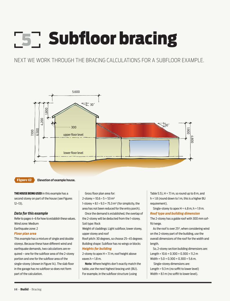
Figure 12
Subfloor bracing
THE HOUSE BEING USED in this example has a
second storey on part of the house (see Figures
12–13).
Data for this exampleRefer to pages 4–6 for how to establish these values.
Wind zone: Medium
Earthquake zone: 2
Floor plan area
This example has a mixture of single and double
storeys. Because these have di£erent wind and
earthquake demands, two calculations are re-
quired – one for the subfloor area of the 2-storey
portion and one for the subfloor area of the
single-storey (shown in Figure 14). The slab floor
in the garage has no subfloor so does not form
part of the calculation.
Gross floor plan area for:
2-storey = 10.6 × 5 = 53 m²
1-storey = 8.1 × 9.3 = 75.3 m² (for simplicity, the
area has not been reduced for the entry porch).
Once the demand is established, the overlap of
the 2-storey will be deducted from the 1-storey.
Soil type: Rock
Weight of claddings: Light subfloor, lower storey,
upper storey and roof
Roof pitch: 30 degrees, so choose 25–45 degrees
Building shape: Subfloor has no wings or blocks
Heights for building
2-storey to apex H = 7.1 m, roof height above
eaves h = 1.8 m.
Note: Where heights don’t exactly match the
table, use the next highest bracing unit (BU).
For example, in the subfloor structure (using
Table 5.5), H = 7.1 m, so round up to 8 m, and
h = 1.8 (round down to 1 m, this is a higher BU
requirement).
Single-storey to apex H = 4.8 m, h = 1.9 m.
Roof type and building dimension
The 2-storey has a gable roof with 300 mm sof-
fit/verge.
As the roof is over 25°, when considering wind
on the 2-storey part of the building, use the
overall dimensions of the roof for the width and
length.
So, 2-storey section building dimensions are:
Length = 10.6 + 0.300 + 0.300 = 11.2 m
Width = 5.0 + 0.300 + 0.300 = 5.6 m.
Single-storey dimensions are:
Length = 9.3 m (no so¡t to lower level)
Width = 8.1 m (no so¡t to lower level).
Elevation of example house.
5.600
30˚
30˚
1.80
0
4.20
06.
500
7.10
0
300
4.800
upper floor level
lower floor level
1.900
5NEXT WE WORK THROUGH THE BRACING CALCULATIONS FOR A SUBFLOOR EXAMPLE.
Build — Bracing— 15
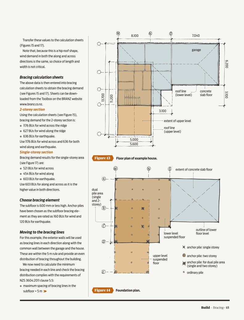
Figure 13
Figure 14
Floor plan of example house.
Foundation plan.
Transfer these values to the calculation sheets
(Figures 15 and 17).
Note that, because this is a hip roof shape,
wind demand in both the along and across
directions is the same, so choice of length and
width is not critical.
Bracing calculation sheetsThe above data is then entered into bracing
calculation sheets to obtain the bracing demand
(see Figures 15 and 17). Sheets can be down-
loaded from the Toolbox on the BRANZ website
www.branz.co.nz.
2-storey section
Using the calculation sheets (see Figure 15),
bracing demand for the 2-storey section is:
○ 1176 BUs for wind across the ridge
○ 627 BUs for wind along the ridge
○ 636 BUs for earthquake.
Use 1176 BUs for wind across and 636 for both
wind along and earthquake.
Single-storey section
Bracing demand results for the single-storey area
(see Figure 17) are:
○ 521 BUs for wind across
○ 454 BUs for wind along
○ 603 BUs for earthquake.
Use 603 BUs for along and across as it is the
higher value in both directions.
Choose bracing elementThe subfloor is 600 mm or less high. Anchor piles
have been chosen as the subfloor bracing ele-
ment as they are rated as 160 BUs for wind and
120 BUs for earthquake.
Moving to the bracing linesFor this example, the exterior walls will be used
as bracing lines in each direction along with the
common wall between the garage and the house.
These are within the 5 m rule and provide an even
distribution of bracing throughout the building.
We now need to calculate the minimum
bracing needed in each line and check the bracing
distribution complies with the requirements of
NZS 3604:2011 clause 5.5:
○ maximum spacing of bracing lines in the
subfloor = 5 m
6.200
3.100
8.100 7.040
3.100
5.0005.600
13.7
00
11.2
00
M N 0
garage
concrete slab floor
roof line (lower level)
roof line (upper level)
extent of upper level
M N 0
A
B
C
D
E
upper level suspended floor
lower level suspended floor
extent of concrete slab floor
outline of lower floor level
dual pile area (single and 2- storey)
anchor pile: single storey
anchor pile: two storey
anchor pile: for dual pile area (single and two storey)
ordinary pile
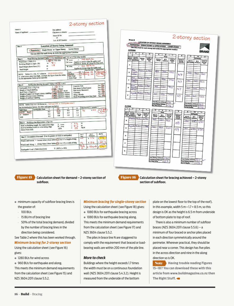
16 — Build — Bracing
Note
Figure 15 Figure 16Calculation sheet for demand – 2-storey section of subfloor.
Calculation sheet for bracing achieved – 2-storey section of subfloor.
○ minimum capacity of subfloor bracing lines is
the greater of:
• 100 BUs
• 15 BU/m of bracing line
• 50% of the total bracing demand, divided
by the number of bracing lines in the
direction being considered.
See Table 2 where this has been worked through.
Minimum bracing for 2-storey section
Using the calculation sheet (see Figure 16)
gives:
○ 1280 BUs for wind across
○ 960 BUs for earthquake and along.
This meets the minimum demand requirements
from the calculation sheet (see Figure 15) and
NZS 3604:2011 clause 5.5.2.
Minimum bracing for single-storey section
Using the calculation sheet (see Figure 18) gives:
○ 1080 BUs for earthquake bracing across
○ 1080 BUs for earthquake bracing along.
This meets the minimum demand requirements
from the calculation sheet (see Figure 17) and
NZS 3604 clause 5.5.2.
The piles in brace line N are staggered to
comply with the requirement that braced or load-
bearing walls are within 200 mm of the pile line.
More to checkBuildings where the height exceeds 1.7 times
the width must be on a continuous foundation
wall (NZS 3604:2011 clause 5.4.3.2). Height is
measured from the underside of the bottom
plate on the lowest floor to the top of the roof).
In this example, width 5 m × 1.7 = 8.5 m, so this
design is OK as the height is 6.5 m from underside
of bottom plate to top of roof.
There is also a minimum number of subfloor
braces (NZS 3604:2011 clause 5.5.6) – a
minimum of four braced or anchor piles placed
in each direction symmetrically around the
perimeter. Wherever practical, they should be
placed near a corner. This design has five piles
in the across direction and nine in the along
direction so is OK.
Having trouble reading Figures
15–18? You can download these with this
article from www.buildmagazine.co.nz then
The Right Stuff.
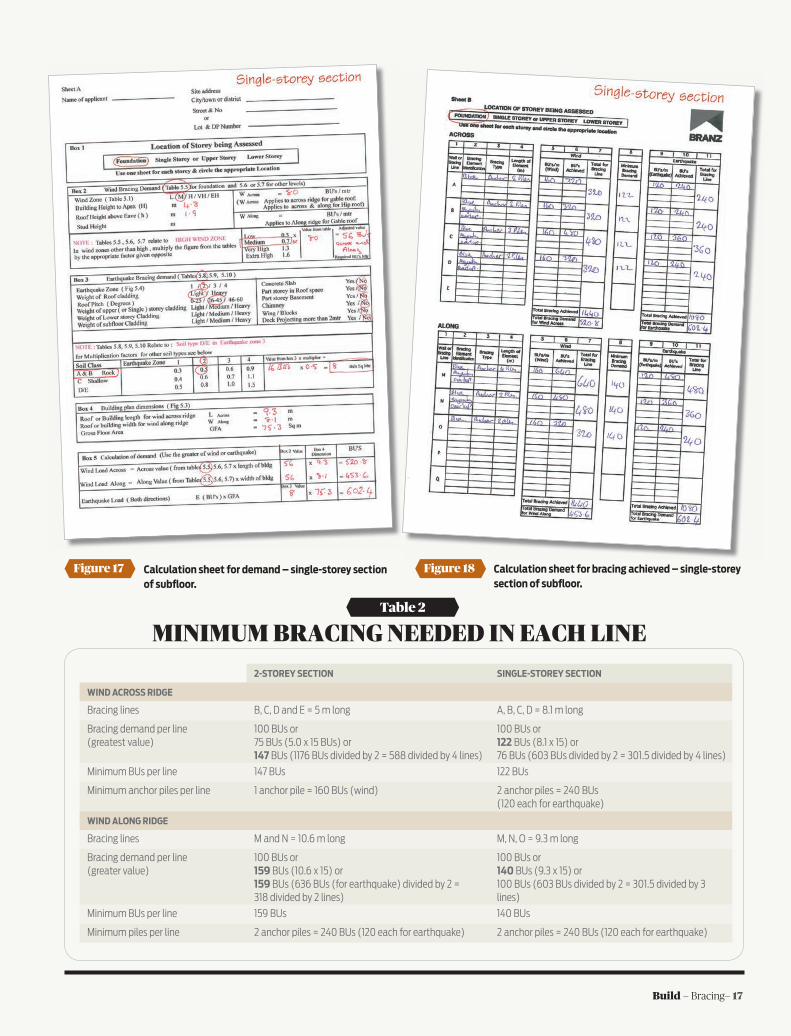
Build — Bracing— 17
MINIMUM BRACING NEEDED IN EACH LINETable 2
2-STOREY SECTION SINGLE-STOREY SECTION
WIND ACROSS RIDGE
Bracing lines B, C, D and E = 5 m long A, B, C, D = 8.1 m long
Bracing demand per line (greatest value)
100 BUs or 75 BUs (5.0 x 15 BUs) or 147 BUs (1176 BUs divided by 2 = 588 divided by 4 lines)
100 BUs or 122 BUs (8.1 x 15) or 76 BUs (603 BUs divided by 2 = 301.5 divided by 4 lines)
Minimum BUs per line 147 BUs 122 BUs
Minimum anchor piles per line 1 anchor pile = 160 BUs (wind) 2 anchor piles = 240 BUs (120 each for earthquake)
WIND ALONG RIDGE
Bracing lines M and N = 10.6 m long M, N, O = 9.3 m long
Bracing demand per line (greater value)
100 BUs or159 BUs (10.6 x 15) or159 BUs (636 BUs (for earthquake) divided by 2 = 318 divided by 2 lines)
100 BUs or 140 BUs (9.3 x 15) or100 BUs (603 BUs divided by 2 = 301.5 divided by 3 lines)
Minimum BUs per line 159 BUs 140 BUs
Minimum piles per line 2 anchor piles = 240 BUs (120 each for earthquake) 2 anchor piles = 240 BUs (120 each for earthquake)
Figure 17 Calculation sheet for demand – single-storey section of subfloor.
Figure 18 Calculation sheet for bracing achieved – single-storey section of subfloor.

18 — Build — Bracing
6
DESIGNERS WILL HAVE NOTICED that there is a
substantial increase in bracing demand from
buildings on slabs to those on suspended floors.
This ranges from about double the demand
for walls of single-storey buildings to about a
30% increase in demand for walls of 2-storey
buildings.
This increase is due to the additional seismic
weight of the suspended floor and its contents
(people, furniture and so on), and the greater
e£ect of earthquake ground movements on
suspended floors.
Experience from ChristchurchObservations in Christchurch after the earth-
quakes clearly showed that piled buildings with a
perimeter foundation wall of concrete or concrete
masonry performed very well, even when there
was ground disturbance due to liquefaction and
lateral spreading.
This is because of the bracing e£ect of the
perimeter foundation wall, together with the
floor acting as a diaphragm.
Gap in NZS 3604NZS 3604:2011 provides two sets of tables for
earthquake bracing demand:
○ Table 5.10 for buildings built on a concrete slab.
○ Tables 5.8 and 5.9 for buildings on a
suspended floor structure.
However, NZS 3604 makes no distinction
between fully piled suspended substructures
and those with a concrete or masonry perimeter
foundation.
Suspended floor structure with semi-detached or half pile.
Bracing design adviceAfter discussions with practitioners, BRANZ
advises:
○ if the building is on a slab, use NZS 3604
Table 5.10
○ if the building is all piled, use NZS 3604 Table
5.8 (single-storey) or 5.9 (two-storey)
○ if the suspended floor structure is well
connected to the perimeter foundation (as
required by NZS 3604 Figure 6.17 for bearers and
Figure 6.16 for wall plates), treat it as a slab
and use Table 5.10
○ if the suspended floor structure is not
connected to the perimeter foundation
(for example, the semi-detached pile in
Figure 19 – a common construction detail
for older timber-framed buildings), then
conservatively Table 5.8 or 5.9 should be
used. Structural engineers experienced
in timber-framed construction could
perhaps justify a demand value
between those from Tables 5.8/5.9 and
Table 5.10.
brick veneer cladding
bearer on DPC
reinforced concrete footing
concrete half pile
floor joists
Figure 19
Bracing for suspended floors
HERE ARE A FEW POINTERS FOR INTERPRETING NZS 3604:2011 BRACING PROVISIONS FOR BUILDINGS WITH SUSPENDED SUBFLOOR STRUCTURES.
Build — Bracing— 19
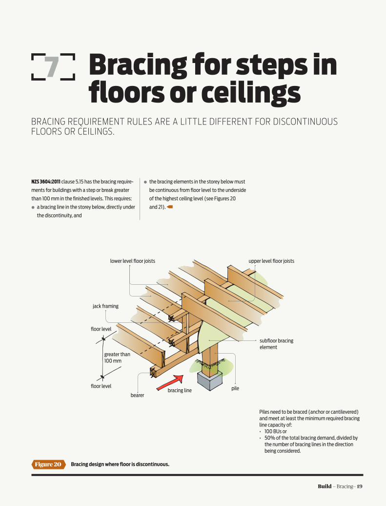
7 Bracing for steps in floors or ceilings
NZS 3604:2011 clause 5.15 has the bracing require-
ments for buildings with a step or break greater
than 100 mm in the finished levels. This requires:
○ a bracing line in the storey below, directly under
the discontinuity, and
○ the bracing elements in the storey below must
be continuous from floor level to the underside
of the highest ceiling level (see Figures 20
and 21).
Figure 20 Bracing design where floor is discontinuous.
Piles need to be braced (anchor or cantilevered) and meet at least the minimum required bracing line capacity of:• 100 BUs or• 50% of the total bracing demand, divided by the number of bracing lines in the direction being considered.
pile
lower level floor joists
jack framing
floor level
greater than 100 mm
bearerbracing line
subfloor bracing element
upper level floor joists
floor level
BRACING REQUIREMENT RULES ARE A LITTLE DIFFERENT FOR DISCONTINUOUS FLOORS OR CEILINGS.

20 — Build — Bracing
ROOF & WALL BRACING SOLUTIONS
ROOF BRACING GABLE END BRACING
Residential/Commercial
for full technical details
www.miteknz.co.nz
Figure 21 Bracing design where ceiling is discontinuous.
The minimum bracing for internal walls in bracing lines is:• 100 BUs or• 50% of the total bracing demand, divided by the number of bracing lines in the direction being considered.
Piles on the subfloor bracing line must be anchor or cantilevered or a braced system combination and meet at least the minimum subfloor bracing requirements.
upper level ceiling joists
internal wall bracing element continuous from floor level to underside of highest ceiling level
floor joists (could be slab)
pile (if not on bracing line, must be within 200 mm of the braced wall above)
upper ceiling level
lower ceiling level
bearer
bottom plate
greater than 100 mm
wall framing
bracing line
lower level ceiling joiststop plate

Build — Bracing— 21
8 Wall bracing
Figure 22 Elevation of example house.
5.600
30˚
30˚
1.80
0
4.20
06.
500
7.10
0
300
4.800
upper floor level
lower floor level
1.900
4.20
0
THE SAME BUILDING is being used as for the sub-
floor bracing (see pages 14–17) with additional
information in Figures 22 and 23.
Data for calculation sheets for this exampleWind zone: Medium
Earthquake: Zone 2
Floor plan areas
The example building is part 2-storey, part single-
storey. The garage is on a slab, and the remainder
has a subfloor.
Because these have di£erent wind and
earthquake demands, the building is divided
into four areas – upper of 2-storey, lower of
2-storey, single-storey and garage – and four
calculations are needed, one for each of these.
The gross floor plan area for the:
○ 2-storey = 10.6 × 5.0 = 53 m²
○ 1-storey = 8.1 × 9.3 = 75.3 m² (for simplicity,
the area has not been reduced for the porch
entry)
○ garage area = 6.2 × 7.040 = 43.6 m²
Soil type: Rock
Cladding weights: Light lower storey, upper
storey and roof
Roof pitch: 30 degrees, so choose 25–45 degrees
Heights for building:
○ Lower of 2-storey to apex H = 6.5 m, h = 1.8 m
○ Upper storey to apex H = 4.2 m, h = 1.8 m
○ 1-storey to apex H = 4.8 m, h = 1.9 m
○ Garage to apex H = 4.8 m, h = 1.9 m
Roof type and building dimension
As the roof pitch is over 25 degrees, when
considering wind for the 2-storey part of the
building, use the overall dimensions of the roof
width and length.
So, 2-storey section (upper and lower levels) are:
○ length = 10.6 + 0.300 + 0.300 = 11.2 m
○ width = 5.0 + 0.300 + 0.300 = 5.6 m
○ single-storey: length = 6.2 + 3.1 = 9.3 m, width
= 8.1 m (no roof overhangs)
○ garage: length = 7.040 m, width = 6.2 m (no
roof overhangs).
Bracing lines and spacingsUse the same bracing layout as for the subfloor
on page 15 (see Figures 23 and 28).
NEXT UP, WE LOOK AT CALCULATING WALL BRACING REQUIREMENTS FOR A BUILDING.
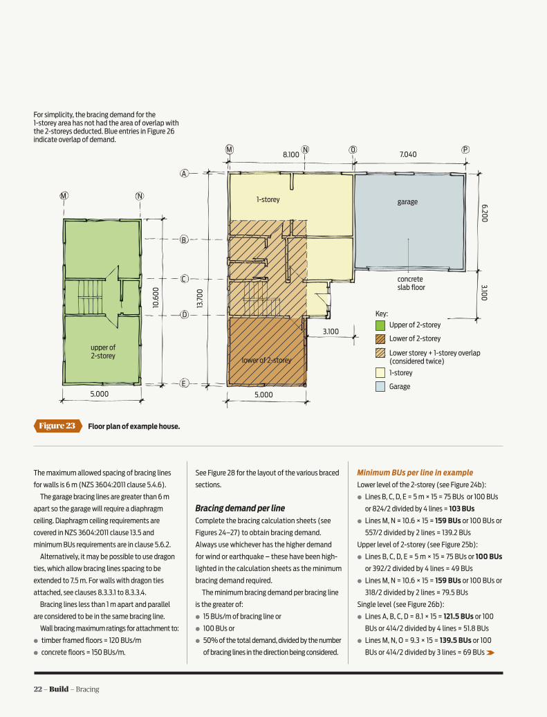
22 — Build — Bracing
The maximum allowed spacing of bracing lines
for walls is 6 m (NZS 3604:2011 clause 5.4.6).
The garage bracing lines are greater than 6 m
apart so the garage will require a diaphragm
ceiling. Diaphragm ceiling requirements are
covered in NZS 3604:2011 clause 13.5 and
minimum BUs requirements are in clause 5.6.2.
Alternatively, it may be possible to use dragon
ties, which allow bracing lines spacing to be
extended to 7.5 m. For walls with dragon ties
attached, see clauses 8.3.3.1 to 8.3.3.4.
Bracing lines less than 1 m apart and parallel
are considered to be in the same bracing line.
Wall bracing maximum ratings for attachment to:
○ timber framed floors = 120 BUs/m
○ concrete floors = 150 BUs/m.
See Figure 28 for the layout of the various braced
sections.
Bracing demand per lineComplete the bracing calculation sheets (see
Figures 24–27) to obtain bracing demand.
Always use whichever has the higher demand
for wind or earthquake – these have been high-
lighted in the calculation sheets as the minimum
bracing demand required.
The minimum bracing demand per bracing line
is the greater of:
○ 15 BUs/m of bracing line or
○ 100 BUs or
○ 50% of the total demand, divided by the number
of bracing lines in the direction being considered.
Minimum BUs per line in example
Lower level of the 2-storey (see Figure 24b):
○ Lines B, C, D, E = 5 m × 15 = 75 BUs or 100 BUs
or 824/2 divided by 4 lines = 103 BUs
○ Lines M, N = 10.6 × 15 = 159 BUs or 100 BUs or
557/2 divided by 2 lines = 139.2 BUs
Upper level of 2-storey (see Figure 25b):
○ Lines B, C, D, E = 5 m × 15 = 75 BUs or 100 BUs
or 392/2 divided by 4 lines = 49 BUs
○ Lines M, N = 10.6 × 15 = 159 BUs or 100 BUs or
318/2 divided by 2 lines = 79.5 BUs
Single level (see Figure 26b):
○ Lines A, B, C, D = 8.1 × 15 = 121.5 BUs or 100
BUs or 414/2 divided by 4 lines = 51.8 BUs
○ Lines M, N, O = 9.3 × 15 = 139.5 BUs or 100
BUs or 414/2 divided by 3 lines = 69 BUs
Figure 23 Floor plan of example house.
6.200
3.100
8.100 7.040
3.100
5.0005.000
13.7
00
10.6
00
M N 0
garage
concrete slab floor
lower of 2-storey
upper of 2-storey
M N
D
A
C
B
E
1-storey
P
Key:
Upper of 2-storey
Lower of 2-storey
1-storey
Lower storey + 1-storey overlap (considered twice)
Garage
For simplicity, the bracing demand for the 1-storey area has not had the area of overlap with the 2-storeys deducted. Blue entries in Figure 26 indicate overlap of demand.

Build — Bracing— 23
Figure 24 Calculation sheet bracing achieved – lower level of 2-storey.
Figure 25 Calculation sheet for bracing achieved – upper level of 2-storey.

24 — Build — Bracing
Figure 26 Calculation sheet for demand – single level. Blue entries indicate overlap with 2-storey.
Figure 27 Garage – demand and bracing.

Build — Bracing— 25
M N 0
garage
ground floorupper level
M N
D
A
C
B
E
M4 A1N5
01 A2 P1
C4P2C5
N3
C3
B3B2
C2
D2
N4
M3E2
M2E1
D1N2
B1M1 N1
C1
Figure 28 Final bracing plan.
P
02
D3
Garage (see Fig 27b):
○ Lines A, C = 7.040 × 15 = 105.6 BUs or 100
BUs or 247/2 divided by 2 lines = 62 BUs
○ Lines O, P = 6.2 × 15 = 93 BUs or 100 BUs or
217/2 divided by 2 lines = 54.25 BUs
Transfer these values to the appropriate bracing
sheets.
Choose bracing elementBracing materials used are sheet products (ply,
plasterboard, fibre cement and so on), concrete,
concrete blocks or metal components. All brac-
ing units are achieved using proprietary products
that have had their bracing rating validated by
the P21 test. The rating may vary for earthquake,
wind and also for the length used. For exam-
ple, a sheet material that is rated as achieving
120 BUs for wind, may have a lesser rating when
used for earthquake or the sheet width is less
than the manufacturer’s minimum width.
BUs ratings are all derived from testing
elements at 2.4 m high. Bracing elements of
other heights will require the BUs achieved to be
calculated for the height used using clause 8.3.1.4
of NZS 3604:2011.
In this example
For this exercise, a generic plasterboard has
been used with a rating of 120 BUs for wind and
100 BUs for earthquake. This has been given the
designation ‘Plstr 1’ in the worksheets.
For the bracing sheets either side of the
garage door in bracing line C, a generic ply has
been chosen, designated in the worksheet as
‘Ply 1’. This has a rating of 150 BU/m for wind
and earthquake. Proprietary sheet linings tested
by manufacturers usually require some form of
hold-downs – always follow the manufacturer’s
details. Never mix details from di£erent systems.
Having trouble reading Figures
24–27? You can download these with this
article from www.buildmagazine.co.nz, then
The Right Stu¤.
Note
26 — Build — Bracing
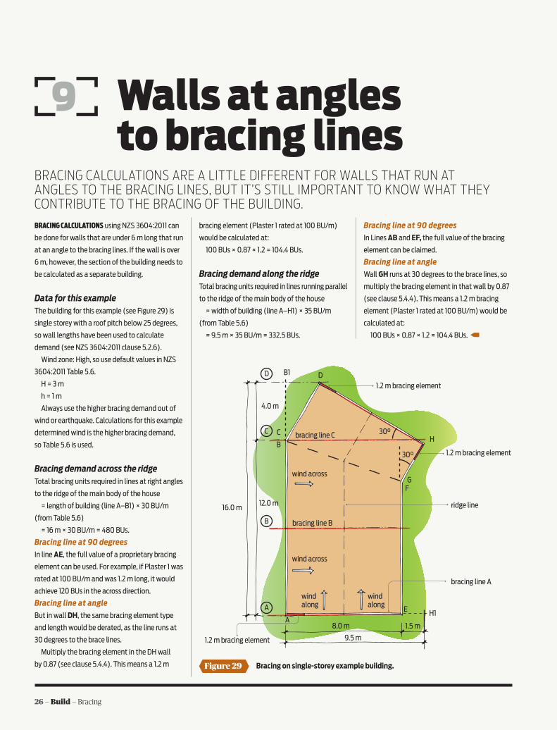
BRACING CALCULATIONS ARE A LITTLE DIFFERENT FOR WALLS THAT RUN AT ANGLES TO THE BRACING LINES, BUT IT’S STILL IMPORTANT TO KNOW WHAT THEY CONTRIBUTE TO THE BRACING OF THE BUILDING.
Figure 29 Bracing on single-storey example building.
8.0 m
wind along
wind along
wind across
30°
1.2 m bracing element
16.0 m12.0 m
4.0 m
wind across
1.2 m bracing element
1.2 m bracing element
A
B
C
D
AE H1
H
GF
B
C
DB1
30°
bracing line C
bracing line B
bracing line A
ridge line
Walls at angles to bracing lines
BRACING CALCULATIONS using NZS 3604:2011 can
be done for walls that are under 6 m long that run
at an angle to the bracing lines. If the wall is over
6 m, however, the section of the building needs to
be calculated as a separate building.
Data for this exampleThe building for this example (see Figure 29) is
single storey with a roof pitch below 25 degrees,
so wall lengths have been used to calculate
demand (see NZS 3604:2011 clause 5.2.6).
Wind zone: High, so use default values in NZS
3604:2011 Table 5.6.
H = 3 m
h = 1 m
Always use the higher bracing demand out of
wind or earthquake. Calculations for this example
determined wind is the higher bracing demand,
so Table 5.6 is used.
Bracing demand across the ridgeTotal bracing units required in lines at right angles
to the ridge of the main body of the house
= length of building (line A–B1) × 30 BU/m
(from Table 5.6)
= 16 m × 30 BU/m = 480 BUs.
Bracing line at 90 degrees
In line AE, the full value of a proprietary bracing
element can be used. For example, if Plaster 1 was
rated at 100 BU/m and was 1.2 m long, it would
achieve 120 BUs in the across direction.
Bracing line at angle
But in wall DH, the same bracing element type
and length would be derated, as the line runs at
30 degrees to the brace lines.
Multiply the bracing element in the DH wall
by 0.87 (see clause 5.4.4). This means a 1.2 m
bracing element (Plaster 1 rated at 100 BU/m)
would be calculated at:
100 BUs × 0.87 × 1.2 = 104.4 BUs.
Bracing demand along the ridgeTotal bracing units required in lines running parallel
to the ridge of the main body of the house
= width of building (line A–H1) × 35 BU/m
(from Table 5.6)
= 9.5 m × 35 BU/m = 332.5 BUs.
Bracing line at 90 degrees
In Lines AB and EF, the full value of the bracing
element can be claimed.
Bracing line at angle
Wall GH runs at 30 degrees to the brace lines, so
multiply the bracing element in that wall by 0.87
(see clause 5.4.4). This means a 1.2 m bracing
element (Plaster 1 rated at 100 BU/m) would be
calculated at:
100 BUs × 0.87 × 1.2 = 104.4 BUs.
1.5 m
9.5 m
9
Build — Bracing— 27
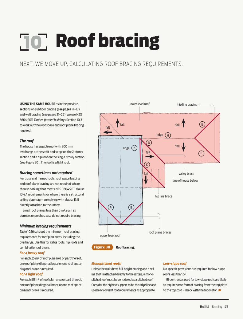
Figure 30 Roof bracing.
roof plane braces
hip line brace
hip line bracing
valley brace
line of house below
upper level roof
lower level roof
A B
C
D
E
F
K
Hridge
ridge
fallfall
fall
fall
fall
fall
Roof bracing 10NEXT, WE MOVE UP, CALCULATING ROOF BRACING REQUIREMENTS.
USING THE SAME HOUSE as in the previous
sections on subfloor bracing (see pages 14–17)
and wall bracing (see pages 21–25), we use NZS
3604:2011 Timber-framed buildings Section 10.3
to work out the roof space and roof plane bracing
required.
The roofThe house has a gable roof with 300 mm
overhangs at the so¡t and verge on the 2-storey
section and a hip roof on the single-storey section
(see Figure 30). The roof is a light roof.
Bracing sometimes not requiredFor truss and framed roofs, roof space bracing
and roof plane bracing are not required where
there is sarking that meets NZS 3604:2011 clause
10.4.4 requirements or where there is a structural
ceiling diaphragm complying with clause 13.5
directly attached to the rafters.
Small roof planes less than 6 m², such as
dormers or porches, also do not require bracing.
Minimum bracing requirementsTable 10.16 sets out the minimum roof bracing
requirements for roof plan areas, including the
overhangs. Use this for gable roofs, hip roofs and
combinations of these.
For a heavy roof
For each 25 m² of roof plan area or part thereof,
one roof plane diagonal brace or one roof space
diagonal brace is required.
For a light roof
For each 50 m² of roof plan area or part thereof,
one roof plane diagonal brace or one roof space
diagonal brace is required.
Monopitched roofs
Unless the walls have full-height bracing and a ceil-
ing that is attached directly to the rafters, a mono-
pitched roof must be considered as a pitched roof.
Consider the highest support to be the ridge line and
use heavy or light roof requirements as appropriate.
Low-slope roof
No specific provisions are required for low-slope
roofs less than 5°.
Girder trusses used for low-slope roofs are likely
to require some form of bracing from the top plate
to the top cord – check with the fabricator.
28 — Build — Bracing
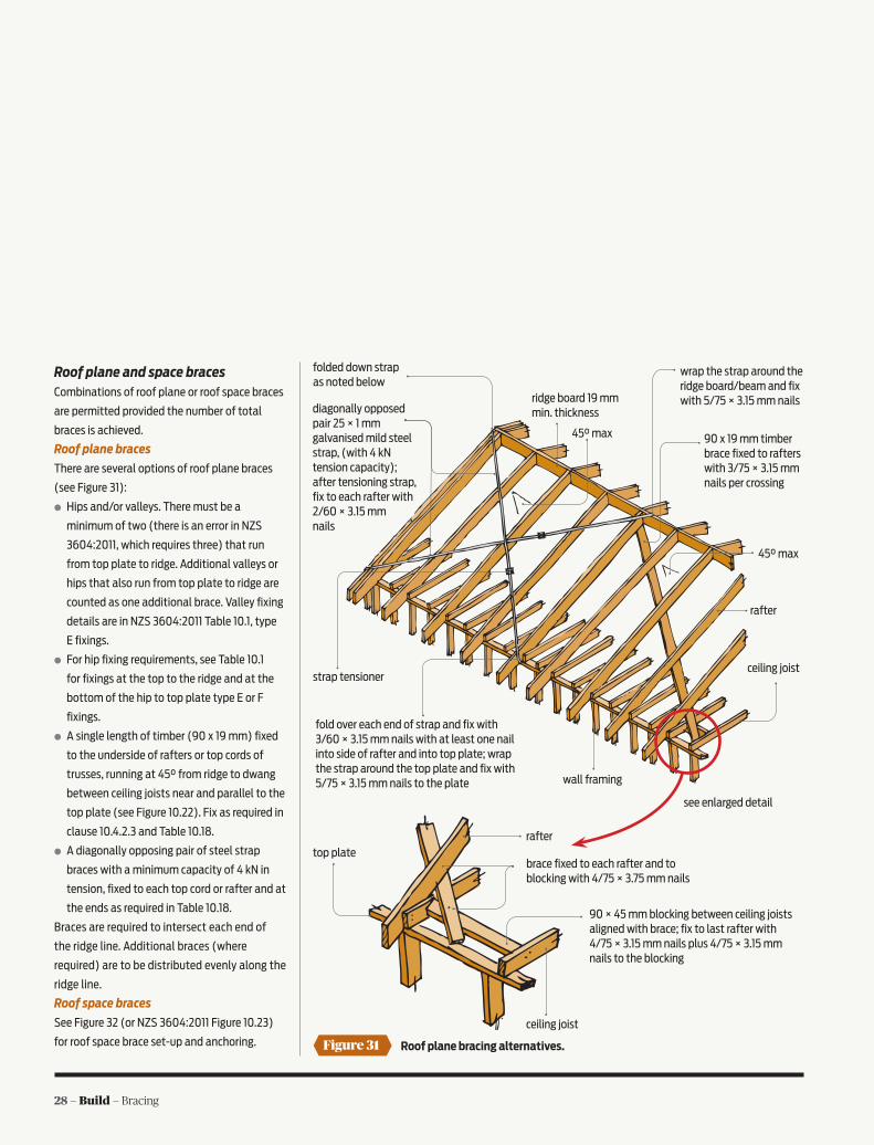
Roof plane and space bracesCombinations of roof plane or roof space braces
are permitted provided the number of total
braces is achieved.
Roof plane braces
There are several options of roof plane braces
(see Figure 31):
○ Hips and/or valleys. There must be a
minimum of two (there is an error in NZS
3604:2011, which requires three) that run
from top plate to ridge. Additional valleys or
hips that also run from top plate to ridge are
counted as one additional brace. Valley fixing
details are in NZS 3604:2011 Table 10.1, type
E fixings.
○ For hip fixing requirements, see Table 10.1
for fixings at the top to the ridge and at the
bottom of the hip to top plate type E or F
fixings.
○ A single length of timber (90 x 19 mm) fixed
to the underside of rafters or top cords of
trusses, running at 45° from ridge to dwang
between ceiling joists near and parallel to the
top plate (see Figure 10.22). Fix as required in
clause 10.4.2.3 and Table 10.18.
○ A diagonally opposing pair of steel strap
braces with a minimum capacity of 4 kN in
tension, fixed to each top cord or rafter and at
the ends as required in Table 10.18.
Braces are required to intersect each end of
the ridge line. Additional braces (where
required) are to be distributed evenly along the
ridge line.
Roof space braces
See Figure 32 (or NZS 3604:2011 Figure 10.23)
for roof space brace set-up and anchoring. Figure 31 Roof plane bracing alternatives.
ceiling joist
raftertop plate
brace fixed to each rafter and to blocking with 4/75 × 3.75 mm nails
90 × 45 mm blocking between ceiling joists aligned with brace; fix to last rafter with 4/75 × 3.15 mm nails plus 4/75 × 3.15 mm nails to the blocking
folded down strap as noted below
diagonally opposed pair 25 × 1 mm galvanised mild steel strap, (with 4 kN tension capacity); after tensioning strap, fix to each rafter with 2/60 × 3.15 mm nails
strap tensioner
fold over each end of strap and fix with 3/60 × 3.15 mm nails with at least one nail into side of rafter and into top plate; wrap the strap around the top plate and fix with 5/75 × 3.15 mm nails to the plate wall framing
ceiling joist
rafter
45° max
45° max 90 x 19 mm timber brace fixed to rafters with 3/75 × 3.15 mm nails per crossing
ridge board 19 mm min. thickness
wrap the strap around the ridge board/beam and fix with 5/75 × 3.15 mm nails
see enlarged detail

Build — Bracing— 29
Back to the exampleThe upper storey roof plan area is 5.6 × 11.2 =
62.72 m².
One roof brace is required per 50 m² with a
minimum of two per ridge line.
Upper storey solution – a minimum of two
braces are required for the upper storey roof (see
Figure 30). Braces are marked in red (A and B).
The lower roof plan area (no so¡t) = (7.040 ×
6.2) + (8.1 × 3.1) + (6.2 × 3.1) = 68.7 m².
One roof brace is required per 50 m² with a
minimum of two per ridge line.
Lower roof solution – minimum of two braces
are required for the lower storey roof but also a
minimum of two per ridge line (see Figure 30).
The hips and valleys already provided will su¡ce
without any additional braces. In Figure 30, the
braces are marked in red (C and D for ridge line K
and E and F for ridge line H).
Note: Braces must be installed with alternating slopes where more than one brace is required.
Figure 32 Roof space bracing.
rafter ridge 45° max.
ceiling joistrunner
brace
rafter
for braces less than 2 m, use 90 × 45 mm
fix brace to runner with 3/100 × 3.75 mm nails
70 × 45 mm on edge (min.) runner spanning over at least four ceiling joists (two each side of brace)
ceiling joist
runner to be within 300 mm laterally of a braced wall (or above a diaphragm ceiling)
top plate of braced wall – fix ceiling joists to wall with 2/100 × 3.75 mm skew nails
fix brace to runner with 3/100 × 3.75 mm nails
ridge board
3/100 × 3.75 mm nails to each side
Note: Max. brace slope to horizontal is 45°.
rafter
brace may also fix to ridge as above
90 × 45 mm blocking 2/100 × 3.75 mm nails each end
fix braces together at packing with 2/100 × 3.75 mm nails each side
fix bottom of brace to runner as above
rafter
for braces 2 m or longer, use 2/90 × 45 mm with packing between at 1 m crs
Figure 34 Roof space bracing.
Figure 33 Roof plane bracing.
ridge board
roof
plane braces
ridge board
roof
space braces

30 — Build — Bracing
RECENT BRANZ TESTING HAS QUANTIFIED THE BRACING RATINGS OF SOME COMMON OLDER GENERIC BRACING SYSTEMS. THESE RATINGS WILL BE USEFUL DURING REPAIRS OR RENOVATIONS OF OLDER BUILDINGS.
Bracing ratings
FOR NEW HOUSES, manufacturers
generally provide wall bracing
ratings for their proprietary
systems based on results of the
BRANZ P21 test method. Designers
then ensure that the demand wind
or earthquake loads at each level
and in each direction are less than
the sum of the resistances of the
bracing elements.
For renovations or repairs of
older buildings, however, the
bracing strength of existing
construction is often not known.
What should be used in the bracing
calculations required by building
consent authorities?
BRANZ tested older systemsIn a Building Research Levy-funded
project, BRANZ tested a range of
older bracing systems (see Table 3) to provide
wall bracing ratings.
In most cases, 2.42 m high timber frames were
constructed using 90 × 45 mm kiln-dried MSG 8
radiata pine timber with plates nailed to studs
with two 90 × 3.15 mm power-driven glue-shank
nails. Although these di£er from the original
timber and nails, the di£erence in performance
is considered small.
11
The bottom plates of the walls were fixed to
the foundation beam using pairs of 100 × 4 mm
hand-driven galvanised nails at 600 mm centres
starting 150 mm from the outside stud.
Nogs, where used, were at 800 mm centres
except for system Brace 4, where they were at
600 mm centres.
Studs were at 600 mm centres (although in
practice they were often at 450 mm centres)
except for Lath 1 where they were at
400 mm centres.
Each specimen was subjected
to three cycles of in-plane
displacement at top plate level to
each of +/-8.5 mm, +/-15 mm, +/-22
mm, +/-29 mm, +/-36 mm, +/-43
mm and +/-65 mm.
...and established bracing ratingsThe proposed bracing ratings
for existing and renovated walls
based on the BRANZ testing are in
Table 1.
Budgetary constraints meant
that it was not possible to test
three replicates of each system
but the bracing contributions are
generally quite low, meaning that
any variations in actual strength
compared to the tested strength
would not influence the overall resistance of
the structure markedly. For more BRANZ Study Report SR305 Bracing
ratings for non-proprietary bracing walls can be
downloaded from www.branz.co.nz.
The Brace 3 specimen – double diagonal braces cut between studs.
Figure 35
Build — Bracing— 31
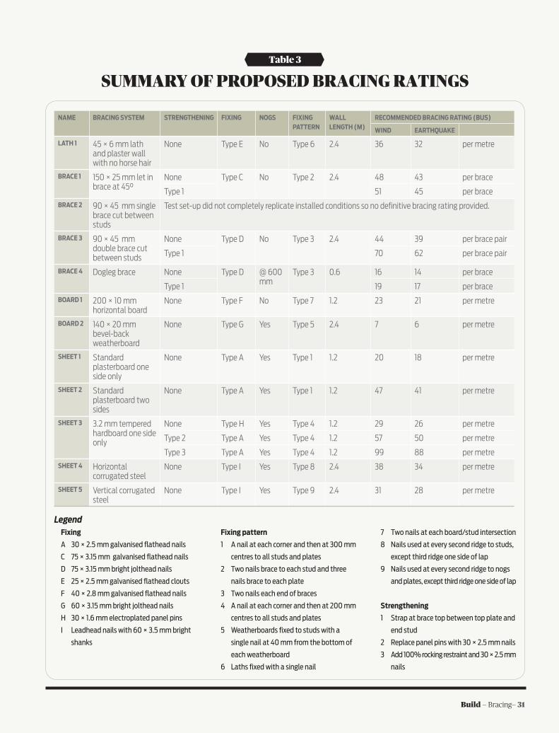
NAME BRACING SYSTEM STRENGTHENING FIXING NOGS FIXING PATTERN
WALL LENGTH (M)
RECOMMENDED BRACING RATING (BUS)
WIND EARTHQUAKE
LATH 1 45 × 6 mm lath and plaster wall with no horse hair
None Type E No Type 6 2.4 36 32 per metre
BRACE 1 150 × 25 mm let in brace at 45°
None Type C No Type 2 2.4 48 43 per brace
Type 1 51 45 per brace
BRACE 2 90 × 45 mm single brace cut between studs
Test set-up did not completely replicate installed conditions so no definitive bracing rating provided.
BRACE 3 90 × 45 mm double brace cut between studs
None Type D No Type 3 2.4 44 39 per brace pair
Type 1 70 62 per brace pair
BRACE 4 Dogleg brace None Type D @ 600 mm
Type 3 0.6 16 14 per brace
Type 1 19 17 per brace
BOARD 1 200 × 10 mm horizontal board
None Type F No Type 7 1.2 23 21 per metre
BOARD 2 140 × 20 mm bevel-back weatherboard
None Type G Yes Type 5 2.4 7 6 per metre
SHEET 1 Standard plasterboard one side only
None Type A Yes Type 1 1.2 20 18 per metre
SHEET 2 Standard plasterboard two sides
None Type A Yes Type 1 1.2 47 41 per metre
SHEET 3 3.2 mm tempered hardboard one side only
None Type H Yes Type 4 1.2 29 26 per metre
Type 2 Type A Yes Type 4 1.2 57 50 per metre
Type 3 Type A Yes Type 4 1.2 99 88 per metre
SHEET 4 Horizontal corrugated steel
None Type I Yes Type 8 2.4 38 34 per metre
SHEET 5 Vertical corrugated steel
None Type I Yes Type 9 2.4 31 28 per metre
Table 3
SUMMARY OF PROPOSED BRACING RATINGS
LegendFixing
A 30 × 2.5 mm galvanised flathead nails
C 75 × 3.15 mm galvanised flathead nails
D 75 × 3.15 mm bright jolthead nails
E 25 × 2.5 mm galvanised flathead clouts
F 40 × 2.8 mm galvanised flathead nails
G 60 × 3.15 mm bright jolthead nails
H 30 × 1.6 mm electroplated panel pins
I Leadhead nails with 60 × 3.5 mm bright
shanks
Fixing pattern
1 A nail at each corner and then at 300 mm
centres to all studs and plates
2 Two nails brace to each stud and three
nails brace to each plate
3 Two nails each end of braces
4 A nail at each corner and then at 200 mm
centres to all studs and plates
5 Weatherboards fixed to studs with a
single nail at 40 mm from the bottom of
each weatherboard
6 Laths fixed with a single nail
7 Two nails at each board/stud intersection
8 Nails used at every second ridge to studs,
except third ridge one side of lap
9 Nails used at every second ridge to nogs
and plates, except third ridge one side of lap
Strengthening
1 Strap at brace top between top plate and
end stud
2 Replace panel pins with 30 × 2.5 mm nails
3 Add 100% rocking restraint and 30 × 2.5 mm
nails

32 — Build — BracingVISIT OUR WEBSITE TO DOWNLOAD THE BRACING CALCULATOR
www.gammabracing.co.nz
• CodemarkCertified
• BuildingCodeCompliant
• allowsseamlessplasterBoardfixingandstopping
• withstandsmultipleearthquakeandwindtraumas
• fornew&existingBuilding
• fitswithinexistingBuildings
• eliminatestheneedformosttemporaryBraCing
• CosteffeCtive&easytoinstall
• speedsuptheBuildingproCess
PROTECT YOUR FAMILY AND HOME AGAINST EARTHQUAKES WITH GAMMA BRACING FRAMES
GAMMABRACINGFRAME
MS 20575 Build
� PROVEN tough and strong
� GUARANTEED quality
� ECO FRIENDLY - rated as Super E0less than 0.3mg/l formaldehyde emissions(AS/NZ Standard 2098:11)
� LIGHT & EASY to handle
� SIMPLE to install. Can be used in conjunctionwith GIB® plasterboard
� SUITABLE for use on light timber-framedbuildings constructed to conform toNZ 3604:2011
PRODUCT CERTIFIEDtested STRUCTURAL
IPL Tuffply Bracing is made tough and strong at Greymouth fromrenewable New Zealand plantation grown Pinus Radiata.
IPL plywood offers unsurpassed quality backed by the EWPAAaudited quality assurance programme.
Available from all leading Building Supply merchants
Tuffply Bracing
INTERNATIONAL PANEL & LUMBER (WEST COAST) LTDFreephone 0800 650 801, Freefax 0800 650 802, Email [email protected]
toughen upyour bracing!

Build — Bracing— 33MS 20575 Build
� PROVEN tough and strong
� GUARANTEED quality
� ECO FRIENDLY - rated as Super E0less than 0.3mg/l formaldehyde emissions(AS/NZ Standard 2098:11)
� LIGHT & EASY to handle
� SIMPLE to install. Can be used in conjunctionwith GIB® plasterboard
� SUITABLE for use on light timber-framedbuildings constructed to conform toNZ 3604:2011
PRODUCT CERTIFIEDtested STRUCTURAL
IPL Tuffply Bracing is made tough and strong at Greymouth fromrenewable New Zealand plantation grown Pinus Radiata.
IPL plywood offers unsurpassed quality backed by the EWPAAaudited quality assurance programme.
Available from all leading Building Supply merchants
Tuffply Bracing
INTERNATIONAL PANEL & LUMBER (WEST COAST) LTDFreephone 0800 650 801, Freefax 0800 650 802, Email [email protected]
toughen upyour bracing!

34 — Build — Bracing
E C O P LY ® :T H E P R O V E NP E R F O R M E R
When it comes to bracing not all structural plywood is created equal. It is now more important than ever to specify product compliant with the NZ Building Code.
Not only is our Ecoply® range of structural plywood independently tested to meet New Zealand bracing standards, we offer in-depth online, technical support and expertise to back up our products.
The EP bracing series has been specifically tested to conform to NZS 3604: 2011. Ecoply EP bracing series simplifies the design and construction of bracing elements using plywood, by itself or in conjunction with GIB® plasterboard.
With this kind of assurance why would you build with anything else?
Ecoply® - Specify with Confidence.
0800 326 759www.chhwoodproducts.co.nz
New ZealandManufactured
IT’S A MATTER OF TRUST