braidwood, units 1 and 2, and byron station, units 1 and 2 ... · duration and improving instrument...
TRANSCRIPT
Exelkn. Exelon Generation wwwexeloncorp corn Nuclear 4300 Winfield Road Warrenville, IL 60555
RS-02-179
October 16, 2002
U. S. Nuclear Regulatory Commission ATTN: Document Control Desk Washington, D.C. 20555-0001
Braidwood Station, Units 1 and 2 Facility Operating License Nos. NPF-72 and NPF-77 NRC Docket Nos. STN 50-456 and STN 50-457
Byron Station, Units 1 and 2 Facility Operating License Nos. NPF-37 and NPF-66 NRC Docket Nos. STN 50-454 and STN 50-455
Subject: Request for Technical Specification Change Extension of Completion Time for Instrument Bus Inverters
In accordance with 10 CFR 50.90, "Application for amendment of license or construction
permit," Exelon Generation Company, LLC (Exelon) is proposing a change to the Technical
Specifications (TS) of Facility Operating License Nos. NPF-72, NPF-77, NPF-37 and NPF-66,
for the Braidwood Station, Units 1 and 2, and the Byron Station, Units 1 and 2, respectively.
The proposed change revises the Completion Time for Required Action A.1 of TS 3.8.7,
"Inverters - Operating," from the current 24 hours for one instrument bus inverter inoperable to
14 days.
The change is being proposed to support on-line maintenance of the instrument bus inverters
and will have a negligible impact on plant safety. The current Completion Time for restoration
of an inoperable instrument bus inverter is insufficient to support the required maintenance and
post-maintenance testing windows. Implementation of this proposed Completion Time
extension would provide the following benefits: (1) allow increased flexibility in the scheduling
and performance of preventive maintenance; (2) avert unplanned plant shutdowns and
minimize the potential need for requests for Notice of Enforcement Discretion (NOED); and
(3) improve instrument bus inverter availability during shutdown modes or conditions.
The justification for extending the Completion Time for an inoperable instrument bus inverter is
based upon a risk-informed and a deterministic evaluation consisting of two main elements:
1) the availability of a separate safety-related constant voltage transformer (CVT) for each
instrument bus, and 2) the application of the Exelon On-Line Work Control procedure while the
instrument bus inverter is inoperable for planned maintenance. These elements provide
adequate justification for approval of the requested TS change by providing high assurance of
A#oo

October 16, 2002 U. S. Nuclear Regulatory Commission Page 2
the capability to provide power to the instrument buses during the instrument bus inverter extended Completion Time.
The risk impact of this extension of the Completion Time associated with TS 3.8.7 Required Action A.1 was evaluated using the upgraded Byron and Braidwood Station Probabilistic Risk Assessment (PRA) models. With one instrument bus being powered from the CVT, the configuration-specific Core Damage Frequency (CDF) increase is negligible, and therefore meets the CDF criteria of < 1.OE-06/year provided in Regulatory Guide (RG) 1.174, "An Approach for Using Probabilistic Risk Assessment in Risk-Informed Decisions on Plant-Specific Changes to the Licensing Basis." The proposed 14-day Completion Time represents an Incremental Conditional Core Damage Probability (ICCDP) which is much less than the ICCDP criteria of 5.OE-07 provided in RG 1.177, "An Approach for Plant-Specific, Risk-Informed Decisionmaking: Technical Specifications," for TS changes. Therefore, this Completion Time revision is considered non-risk significant.
We request approval of the proposed change by October 15, 2003.
This request is subdivided as follows:
1. Attachment A gives a description and safety analysis of the proposed change.
2. Attachments B-1 and B-2 include the marked-up TS pages for the proposed change for Braidwood Station and Byron Station, respectively. Attachments B-3 and B-4 include the associated TS pages with the proposed change incorporated for Braidwood Station and Byron Station, respectively. Attachments B-5 and B-6 include the associated TS Bases pages for information only with the proposed change incorporated for Braidwood Station and Byron Station, respectively.
3. Attachment C describes our evaluation performed using the criteria in 10 CFR 50.91(a)(1), "Notice for public comment," which provides information supporting a finding of no significant hazards consideration using the standards in 10 CFR 50.92(c), "Issuance of amendment."
4. Attachment D provides information supporting an environmental assessment and a finding that the proposed change satisfies the criteria for a categorical exclusion.
5. Attachment E provides a summary of the Byron and Braidwood Station Probabilistic Risk Assessment.
This proposed change has been reviewed by the Braidwood Station and the Byron Station Plant Operations Review Committees and approved by the Nuclear Safety Review Boards in accordance with the requirements of the Quality Assurance Program.
Exelon is notifying the State of Illinois of this application for a change to the TS by sending a copy of this letter and its attachments to the designated State Official.
S 4
October 16, 2002 U. S. Nuclear Regulatory Commission Page 3
Should you have any questions or concerns regarding this letter, please contact J. A. Bauer at (630) 657-2801.
Respectfully,
Keith R. Jury Director - Licensing Mid-west Regional Operating Group
Attachments: Affidavit Attachment A: Description and Safety Analysis of the Proposed Change Attachment B-I: Marked-Up TS Pages for Proposed Change for Braidwood Station
Attachment B-2: Marked-Up TS Pages for Proposed Change for Byron Station Attachment B-3: Incorporated TS Pages for Proposed Change for Braidwood Station
Attachment B-4: Incorporated TS Pages for Proposed Change for Byron Station Attachment B-5: Incorporated TS Bases Pages for Braidwood Station - Information Only
Attachment B-6: Incorporated TS Bases Pages for Byron Station - Information Only Attachment C: Information Supporting a Finding of No Significant Hazards Consideration Attachment D: Information Supporting an Environmental Assessment Attachment E: Summary of the Byron and Braidwood Station Probabilistic Risk Assessment
cc: Regional Administrator - NRC Region III NRC Senior Resident Inspector - Braidwood Station NRC Senior Resident Inspector - Byron Station Office of Nuclear Facility Safety - Illinois Department of Nuclear Safety
STATE OF ILLINOIS
COUNTY OF DUPAGE
IN THE MATTER OF
EXELON GENERATION CO., LLC
BRAIDWOOD STATION - UNITS I and 2
BYRON STATION - UNITS I and 2
) )
)
) )
)
Docket Nos.
STN 50-456 and STN 50-457
STN 50-454 and STN 50-455
SUBJECT: Request for Technical Specification Change Extension of Completion Time for Instrument Bus Inverters
AFFIDAVIT
I affirm that the content of this transmittal is true and correct to the best of my knowledge, information and belief.
Keith R. Jur Director - Licensing Midwest Regional Operating Group
Subscribed and sworn to before me, a Notary Public in and
for the State above named, this day of
___ •___ _ ,2002.
TIOWA.BA ý tky!)blic
( OFFICIAL Z-EAL )
ATTACHMENT A
DESCRIPTION AND SAFETY ANALYSIS OF THE PROPOSED CHANGE
A. SUMMARY OF PROPOSED CHANGE
In accordance with 10 CFR 50.90, "Application for amendment of license or construction permit," Exelon Generation Company, LLC (Exelon) is proposing a change to the Technical Specifications (TS) of Facility Operating License Nos. NPF-72, NPF-77, NPF-37 and NPF-66, for the Braidwood Station, Units 1 and 2, and the Byron Station, Units 1 and 2, respectively. The proposed change revises the Completion Time for Required Action A.1 of TS 3.8.7, "Inverters - Operating," from the current 24 hours for one instrument bus inverter inoperable to 14 days.
The change is being proposed to support on-line maintenance of the instrument bus inverters. The current Completion Time for restoration of an inoperable instrument bus inverter is insufficient to support the required maintenance and post-maintenance testing windows. The change will provide the operational flexibility to allow performance of periodic instrument bus inverter maintenance and post-maintenance testing on-line, reducing plant refueling outage duration and improving instrument bus inverter availability during shutdown conditions.
B. DESCRIPTION OF THE CURRENT REQUIREMENTS
The instrument bus inverters are required to be operable in Modes 1, 2, 3, and 4 to ensure that:
a. Acceptable fuel design limits and reactor coolant pressure boundary limits are not exceeded as a result of anticipated operational occurrences (AOOs) or abnormal transients; and
b. Adequate core cooling is provided, and containment operability and other vital functions are maintained in the event of a postulated design basis accident (DBA).
With a required instrument bus inverter inoperable, its associated AC instrument bus may be inoperable unless it is manually re-energized from its associated constant voltage transformer (CVT). For this reason, a Note has been included in Condition A of TS 3.8.7 requiring entry into the Conditions and Required Actions of TS 3.8.9, "Distribution Systems Operating," for any de-energized instrument bus. This ensures that the instrument bus is re-energized within two hours.
TS 3.8.7 Required Action A.1 currently allows 24 hours to fix the inoperable instrument bus inverter and return it to service. The 24-hour limit is based upon engineering judgment, taking into consideration the time required to repair an instrument bus inverter and the additional risk to which the unit is exposed because of the instrument bus inverter inoperability. This has to be balanced against the risk of an immediate shutdown, along with the potential challenges to safety systems that such a shutdown might entail. When the AC instrument bus is powered from its CVT, it is relying upon interruptible AC electrical power sources (i.e., offsite and onsite). The uninterruptible instrument bus inverter source to the AC instrument buses is the preferred source for powering instrumentation trip setpoint devices.
Page 1 of 15 Attachment A - Description and Safety Analysis
If the inoperable devices or components cannot be restored to operable status within the required Completion Time, the unit must be brought to a mode in which the Limiting Conditions for Operation (LCO) does not apply. To achieve this status, the unit must be brought to at least Mode 3 within six hours and to Mode 5 within 36 hours. The allowed Completion Times are
reasonable, based on operating experience, to reach the required unit conditions from full
power conditions in an orderly manner and without challenging plant systems.
C. BASES FOR THE CURRENT REQUIREMENTS
The instrument bus inverters are the preferred source of power for the AC instrument buses because of the stability and reliability they provide. Each unit is equipped with four AC
instrument buses (i.e., two per division) which are normally supplied AC electrical power by a
dedicated instrument bus inverter. The instrument bus inverters can be powered from an AC
source/rectifier or from an associated 125 VDC battery. The battery provides an uninterruptible power source for the instrumentation and controls for the reactor protection system (RPS) and the engineered safety feature actuation system (ESFAS).
The instrument bus inverters ensure the availability of AC electrical power for the systems instrumentation required to shut down the reactor and maintain it in a safe condition after an AOO or a postulated DBA.
Maintaining the required instrument bus inverters operable ensures that the redundancy
incorporated into the design of the RPS and ESFAS instrumentation and controls is maintained. The four instrument bus inverters ensure an uninterruptible supply of AC electrical power to the AC instrument buses even if the 4.16 kV safety buses are de-energized.
Operable instrument bus inverters require the associated instrument bus to be powered by the
instrument bus inverter with output voltage within tolerances, and power input to the instrument bus inverter from the associated 125 VDC battery. The power supply may be from an AC source via rectifier as long as the battery is connected as the uninterruptible power supply.
D. NEED FOR REVISION OF THE REQUIREMENT
Both the Braidwood Station and the Byron Station have experienced several "failure to operate" events associated with the instrument bus inverters. These events have been primarily due to
failure of control boards, ferro-resonant transformers, and internal components such as capacitors. Control board failures were addressed by a modification of the board by the original
equipment manufacturer (OEM) and the addition of forced cooling to the instrument bus inverter. Since these changes were made, there have been no instrument bus inverter failures associated with the control boards and control board deficiencies have decreased. Ferroresonant transformer failures were caused by age and applied loading profiles. All of the
transformers are scheduled to be replaced at the Braidwood Station and Byron Station in accordance with the preventive maintenance (PM) program.
The OEM identified an issue associated with an electrolytic capacitor in the filter circuit in December 2000. Several failures of these capacitors have been experienced. The capacitor failures did not result in a failure of the instrument bus inverter, but did require unavailability of
Page 2 of 15 Attachment A - Description and Safety Analysis
the instrument bus inverter at power to correct the deficiencies. All affected capacitors have been replaced at both stations.
In addition, a PM program has been established to monitor and evaluate instrument bus inverter performance. This PM program has been effective in reducing deficiencies and failures of the instrument bus inverters. However, while we have improved the reliability of the instrument bus inverters, as a result of having only 24 hours to fix an inoperable instrument bus inverter, "failure to operate" events associated with the instrument bus inverters have lead to the preparation of a Notice of Enforcement Discretion (NOED) on several occasions at both the Braidwood and Byron Stations.
Implementation of this proposed Completion Time extension would provide the following benefits.
" Allow increased flexibility in the scheduling and performance of preventive maintenance. Allowing on-line preventive maintenance provides the flexibility to focus quality resources on any required or elective instrument bus inverter maintenance.
" Avert unplanned plant shutdowns and minimize the potential need for requests for an NOED. Risks incurred by unexpected plant shutdowns can be comparable to and often exceed those associated with continued power operation.
"* Improve instrument bus inverter availability during shutdown modes or conditions.
E. DESCRIPTION OF THE PROPOSED CHANGE
The proposed change revises the Completion Time for Required Action A.1 of TS 3.8.7, "Inverters - Operating," from the current 24 hours for one instrument bus inverter inoperable to 14 days.
F. SAFETY ANALYSIS OF THE PROPOSED CHANGE
The instrument bus inverters are the preferred source of power for the AC instrument buses because of the stability and reliability they provide. Each of the four AC instrument buses (i.e., two per division) is normally supplied AC electrical power by a dedicated instrument bus inverter. The instrument bus inverters can be powered from an AC source/rectifier or from an associated 125 VDC battery. The battery provides an uninterruptible power source for the instrumentation and controls for the RPS and the ESFAS. Additionally, each instrument bus is equipped with a dedicated safety-related CVT. The CVTs are powered from a 480 VAC ESF bus and provides an interruptible source of power for the instrument bus. The quality of the power provided by the CVTs is comparable to the instrument inverters and will have no adverse affect on instrumentation operation or response.
The initial conditions of DBA and transient analyses in the Byron/Braidwood Stations' Updated Safety Analysis Report (UFSAR), Chapter 6, "Engineered Safety Features," and Chapter 15, "Accident Analyses," assume ESF systems are Operable. The instrument bus inverters are designed to provide the required capacity, capability, redundancy, and reliability to ensure the availability of necessary power to the RPS and ESFAS instrumentation and controls so that the fuel, reactor coolant system (RCS), and containment design limits are not exceeded.
Page 3 of 15 Attachment A - Description and Safety Analysis
The operability of the instrument bus inverters is consistent with the initial assumptions of the accident analyses and is based on meeting the design basis of the plants. This includes maintaining required AC instrument buses operable during accident conditions in the event of an assumed loss of all offsite AC power or all onsite AC power sources, and a worst case single failure.
The CVT provides an interruptible source of power. A loss of offsite power (LOOP) with an inoperable instrument bus inverter (i.e., instrument bus being powered by its CVT) will result in a loss of power to the associated instrument bus. Since the CVT is powered from a 480 VAC ESF bus, upon a LOOP with an inoperable instrument bus inverter, power would be restored to the affected instrument bus once the associated diesel generator (DG) re-energizes the 480 VAC ESF bus, and all instruments supplied by the instrument bus would be restored with no adverse impact to the units because no other instrument channels in the opposite train would be expected to be inoperable or in a tripped condition during this time, with the exception of routine surveillances. In order for the instrument bus to remain de-energized, the associated DG would have to fail, there would have to be a failure to re-energize the 480 VAC ESF bus powering the CVT, or the CVT would have to fail to energize the instrument bus. In the event the DG failed (i.e., failed to re-energize the 480 VAC ESF bus), power could still be established to the 480 VAC ESF bus by powering the 4 kV ESF bus from the opposite unit 4 kV ESF bus cross-tie breaker.
In the event of a failure to re-energize the 480 VAC ESF bus or of a CVT failure, the most significant impact on the unit is the failure of one train of ESF equipment to actuate. In this condition, the redundant train of ESF equipment will automatically actuate to mitigate the accident, and the affected unit would remain within the bounds of the accident analyses. In addition, there would be no adverse impact to the unit because no other instrument channels in the opposite train would be expected to be inoperable or in a tripped condition during this time, with the exception of routine surveillances. Since the probability of these events occurring simultaneously during a planned maintenance window is low, there is minimal safety impact due to the requested extended Completion Time.
EVALUATION OF RISK IMPACT
The risk impact of the proposed changes has been evaluated and found to be acceptable. The effect on risk of the proposed increase in Completion Time for restoring an inoperable instrument bus inverter has been evaluated using the NRC three-tier approach suggested in Regulatory Guide (RG) 1.177, "An Approach for Plant-Specific, Risk-Informed Decisionmaking: Technical Specifications," August, 1998 (Reference 1).
Tier 1 - Probabilistic Risk Assessment (PRA) Capability and Insights Tier 2 - Avoidance of Risk-Significant Plant Configurations Tier 3 - Risk-Informed Configuration Risk Management
TIER 1: PRA CAPABILITY AND INSIGHTS
Risk-informed support for the proposed change is based on PRA calculations performed to quantify the change in Core Damage Frequency (CDF) and Large Early Release Frequency (LERF) resulting from the increased Completion Time for the instrument bus inverter.
Page 4 of 15 Attachment A - Description and Safety Analysis
The Byron and Braidwood Stations PRAs were recently upgraded in support of the Emergency Diesel Generator (EDG) Completion Time Extension License Amendment Request in Reference 2. The PRAs address internal events at full power. Other risk sources and operating modes are discussed below. In addition to incorporating recent advances in PRA technology across all elements of the PRA, a special effort was made to ensure that those aspects of the PRA that are potentially sensitive to changes in instrument bus inverter maintenance unavailability are adequate to evaluate the risk impacts of the increased Completion Time for the instrument bus inverters. These elements include a detailed model of the ESFAS system and data analysis of key parameters such as instrument bus inverter failure rates, maintenance unavailabilities, and common cause failure probabilities. Attachment E provides a brief summary of these PRAs.
For the Level 2 analysis (i.e., the containment analysis), LERF was estimated using the methodology in NUREG/CR-6595, "An Approach for Estimating the Frequencies of Various Containment Failure Modes and Bypass Events," January 1999. This approach to LERF evaluation, while simplified, supports a realistic quantification of systemic contributions to containment isolation failures and bypass sequences that are actually derived from the Level 1 event sequence model, and a conservative evaluation of severe accident challenges, which are less important for pressurized water reactors (PWRs) with large dry containments.
The scope, level of detail, and quality of the Byron and Braidwood Stations PRAs are sufficient to support a technically defensible and realistic evaluation of the risk change from this proposed Completion Time extension. Updating and maintenance of the Byron and Braidwood Stations PRAs is controlled under Exelon Nuclear Engineering Procedure, ER-AA-600, "Risk Management."
Peer review certification of the Braidwood Station PRA using the Westinghouse Owners Group Peer Review Certification Guidelines was performed in August 1999. Certification of the Byron Station PRA was performed in July 2000. A team of independent PRA experts from U.S. nuclear utility PRA groups and PRA consultant organizations carried out these peer review certifications. As a result of the considerable effort to incorporate the latest industry insights into the PRA, self-assessments, and certification peer reviews, Exelon is confident that the results of the risk evaluation are technically sound and consistent with the expectations for PRA quality set forth in RG 1.174, "An Approach for Using Probabilistic Risk Assessment in RiskInformed Decisions on Plant-Specific Changes to the Licensing Basis," July 1998 (Reference 3) and RG 1.177.
To determine the effect of the proposed 14-day Completion Time for restoration of an inoperable instrument bus inverter, the guidance suggested in RG 1.174 and RG 1.177 was used. Thus, the following risk metrics were used to evaluate the risk impacts of extending the instrument bus inverter Completion Time from 24 hours to 14 days.
ACDFAvE = change in the annual average CDF due to any increased on-line maintenance unavailability of instrument bus inverters that could result from the increased Completion Time. This risk metric is used to compare against the CDF criterion of RG 1.174 to determine whether a change in CDF is regarded as risk significant. This criterion is a function of the baseline annual average core damage frequency, CDFBASE
ALERFAvE = change in the annual average LERF due to any increased on-line maintenance unavailability of instrument bus inverters that could result from the increased Completion Time. RG 1.174 criteria were also applied to judge the significance of changes in this risk metric.
Page 5 of 15 Attachment A - Description and Safety Analysis

ICCDP{xY} = incremental conditional core damage probability with instrument bus inverter Y on Unit x out-of-service for an interval of time equal to the proposed new Completion Time (i.e.,14 days). This risk metric is used as suggested in RG 1.177 to determine whether a proposed increase in Completion Time has an acceptable risk impact.
ICLERP(xY) = incremental conditional large early release probability with instrument bus inverter Y on Unit x out-of-service for an interval of time equal to the proposed new Completion Time (i.e., 14 days). RG 1.177 criteria were also applied to judge the significance of changes in this risk metric.
The evaluation of the above risk metrics was performed as follows.
The change in the annual average CDF at each reactor Unit x due to the change in the instrument bus inverter Completion Time, ACDFAvE, was evaluated by computing:
ACDF.4V =( TA ~DF + ( Tý 'DF TIC DF.co+ ( T. TCAVE E = +AOOS TB+ ( + I XDrD +
(1 -YA +T. +TC+ TxDD TcYCi x ,RBASE - CDFxBASE
where the following definitions were applied.
CDFJAOOS, CDFXBOOS , CDFxCOOS , CDFxDOOS = CDF evaluated from the PRA model for
Unit x with the instrument bus inverter A/B/C/D out-of-service.
TxA, TxB, Txc, Txo = Total time per fuel cycle (TcycLE) that instrument bus inverter AIB/C/D on Unit x is out of service for the extended Completion Time.
CDFxBASE = baseline annual average CDF for Unit x with average unavailability of instrument bus inverters consistent with the current instrument bus inverter Completion time. This is the CDF result of the current baseline PRAs for each Unit x, where x denotes Braidwood and Byron Stations, Units 1 and 2. Note that there were separate PRA models developed for each of the four units at these two stations.
A similar approach was used to evaluate the change in the average LERF for each Unit x due to the requested Completion Time, ALERFXAvE:
ALERFI =E T.A •ERFA o+ T+ T1 ERF.Boos+( TIcC ERF.cOoS+( T." EERF.oos+
FJT tLCc0J TCYcLE, JCYCLE J
TCYCLE ERFBAsA -LERF•BfsE
where the following definitions were applied.
Page 6 of 15 Attachment A - Description and Safety Analysis
LERFXAOOs, LERFBoos, LERFXcoos, LERFXDoos = LERF evaluated from the PRA model
for Unit x with the instrument bus inverter ANBICID out of service.
LERFBASE = baseline annual average LERF for Unit x with average unavailability of instrument bus inverters consistent with the current instrument bus inverter Completion time. This is the LERF result of the current baseline PRAs for each Unit x, where x denotes Braidwood and Byron Stations, Units 1 and 2. Note that there were separate PRA models developed for each of the four units at these two stations.
The extended completion time is expected to be used no more than once per inverter per refueling cycle, hence TxAoos = TxBoos= Txcoos= TxDoos= 14 days. Since actual maintenance times are expected to be a fraction of the Completion Time, this assumption is conservative.
The incremental conditional core damage probability (ICCDP) and incremental conditional large early release probability (ICLERP) are computed using definitions in RG 1.177. In terms of the above defined parameters, the definition of ICCDP is as follows.
ICCDPXA = (CDFoo - CDFAsE Y
ICCDP, = (CDFAOOs - CDFXBAsE )* (l4days) * (365days / year)-'
ICCDP,A = (CDFAoos - CDFxBAsE )* 3.84xl 0-2
Where the following definition is applied: TCT = the requested Completion Time.
Note that in the above formula, 365 days/year is merely a conversion factor to get the Completion Time units consistent with the CDF frequency units. The ICCDP values are dimensionless probabilities to evaluate the incremental probability of a core damage event over a period of time equal to the extended Completion Time, in comparison with the evaluation of ACDFXAvE in which the CDF is averaged over an 18-month refueling cycle.
Similarly, ICLERP is defined as follows.
ICLERPYA = (LERFXAOOS - LERFXBAsE )*3.84x10⁻²
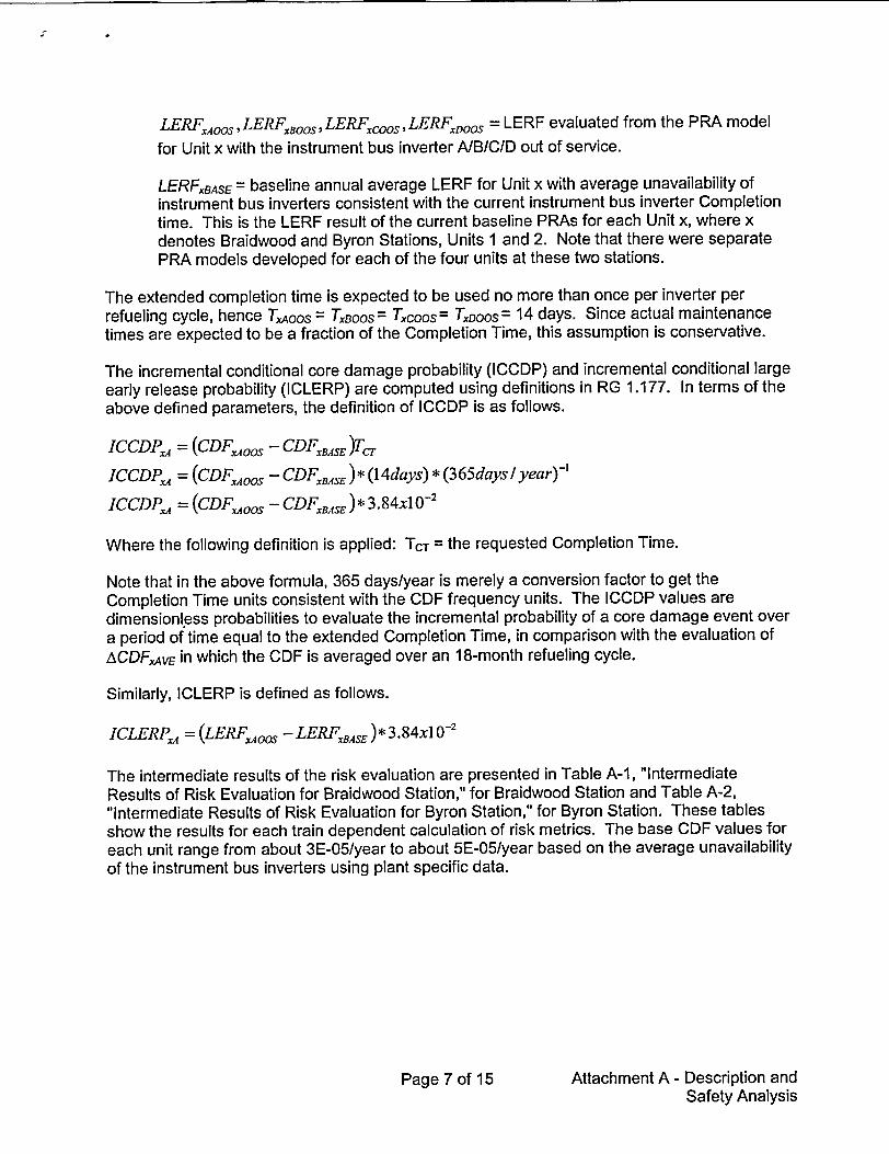
The intermediate results of the risk evaluation are presented in Table A-I, "Intermediate Results of Risk Evaluation for Braidwood Station," for Braidwood Station and Table A-2, "Intermediate Results of Risk Evaluation for Byron Station," for Byron Station. These tables show the results for each train dependent calculation of risk metrics. The base CDF values for each unit range from about 3E-05/year to about 5E-05/year based on the average unavailability of the instrument bus inverters using plant specific data.
Page 7 of 15 Attachment A - Description and Safety Analysis

Table A-1
Intermediate Results of Risk Evaluation for Braidwood Station
Page 8 of 15 Attachment A - Description and Safety Analysis

I I
Table A-2
Intermediate Results of Risk Evaluation for Byron Station
Page 9 of 15 Attachment A - Description and Safety Analysis
Risk Unit I Unit 2
Metric Inverter 111 Inverter 112 Inverter 113 Inverter 114 Inverter 211 Inverter 212 Inverter 213 Inverter 214
CDFXBASE 5E-5 5E-5
CDFXYOOS 5E-5 5E-5 5E-5 5E-5 5E-5 5E-5 5E-5 5E-5
LERFXBASE 5E-6 5E-6
LERFXYOOS 5E-6 5E-6 5E-6 5E-6 5E-6 5E-6 5E-6 5E-6
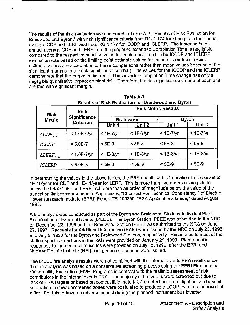
The results of the risk evaluation are compared in Table A-3, "Results of Risk Evaluation for Braidwood and Byron," with risk significance criteria from RG 1.174 for changes in the annual average CDF and LERF and from RG 1.177 for ICCDP and ICLERP. The increase in the annual average CDF and LERF from the proposed extended Completion Time is negligible compared to the respective baseline value for each reactor unit. The ICCDP and ICLERP evaluation was based on the limiting point estimate values for these risk metrics. (Point estimate values are acceptable for these comparisons rather than mean values because of the significant margins to the risk significance criteria.) The values for the ICCDP and the ICLERP demonstrate that the proposed instrument bus inverter Completion Time change has only a negligible quantitative impact on plant risk. Therefore, the risk significance criteria at each unit are met with significant margin.
Table A-3 Results of Risk Evaluation for Braidwood and Byron
Risk Risk Risk Metric Results
Metric Significance Braidwood Byron Metric Criterion Unit I Unit 2 Unit I Unit 2
ACDFAVE < 1.OE-6/yr < 1 E-7/yr < 1 E-7/yr < 1 E-7/yr < 1 E-7/yr
ICCDP < 5.OE-7 < 5E-8 < 5E-8 < 5E-8 < 5E-8
ALERFA•E < 1.OE-7/yr < 1 E-8/yr < 1 E-8/yr < 1 E-8/yr < 1 E-8/yr
ICLERP < 5.OE-8 < 5E-9 < 5E-9 < 5E-9 < 5E-9
In determining the values in the above tables, the PRA quantification truncation limit was set to 1E-10/year for CDF and 1E-11/year for LERF. This is more than five orders of magnitude below the total CDF and LERF and more than an order of magnitude below the value of the truncation limit recommended in Appendix B, "Checklist For Technical Consistency," of Electric Power Research Institute (EPRI) Report TR-1 05396, "PSA Applications Guide," dated August 1995.
A fire analysis was conducted as part of the Byron and Braidwood Stations Individual Plant Examination of External Events (IPEEE). The Byron Station IPEEE was submitted to the NRC on December 23, 1996 and the Braidwood Station IPEEE was submitted to the NRC on June 27, 1997. Requests for Additional Information (RAIs) were issued by the NRC on July 23, 1998 and July 9, 1998 for the Byron and Braidwood Stations, respectively. Responses to most of the station-specific questions in the RAIs were provided on January 29, 1999. Plant-specific responses to the generic fire issues were provided on July 15, 1999, after the EPRI and Nuclear Electric Institute (NEI) final generic responses were issued.
The IPEEE fire analysis results were not combined with the internal events PRA results since the fire analysis was based on a conservative screening process using the EPRI Fire Induced Vulnerability Evaluation (FIVE) Programs in contrast with the realistic assessment of risk contributors in the internal events PRA. The majority of fire zones were screened out due to lack of PRA targets or based on combustible material, fire detection, fire mitigation, and spatial separation. A few unscreened zones were postulated to produce a LOOP event as the result of a fire. For this to have an adverse impact during the planned instrument bus inverter
Page 10 of 15 Attachment A - Description and Safety Analysis
maintenance, the fire would also have to fail the offsite power circuits and the remaining ESF power division. The probability of this combination of failures is judged to be significantly lower
than the truncation limit discussed above. This is consistent with the operating experience at
both plants.
The IPEEE fire risk assessments at the Byron and Braidwood Stations resulted in a low fire
CDF and did not identify any vulnerabilities. The proposed change to the instrument bus inverter Completion Time has a negligible effect, if any, on fire risk. Also, current administrative controls on activities with fire risk (e.g., welding and cutting) are intended to increase the level
of awareness during potentially risk significant activities and reduce fire risk.
The seismic analyses in the Byron and Braidwood Stations' IPEEEs were based on the seismic margin assessment. No significant seismic concerns were identified and it was concluded that
the plants possess significant seismic margin. The proposed change to the instrument bus
inverter Completion Time has a negligible effect on the seismic risk profile at Byron and Braidwood Stations.
Evaluation of high winds, external floods, and other external events in the Byron and Braidwood Stations' IPEEEs, which are in accordance with NUREG-1407, "Procedural and Submittal
Guidance for the Individual Plant Examination of External Events (IPEEE) for Severe Accident
Vulnerabilities," June 1991, indicated that the sites conform to NUREG-0800, "Standard Review
Plan for the Review of Safety Analysis Reports for Nuclear Power Plants," June 1987, criteria and revealed no potential vulnerabilities. The proposed change to the instrument bus inverter
Completion Time extension has a negligible effect on the risk profile at Byron and Braidwood Stations from other external events.
The risk evaluation reported in this submittal shows that changes in risk due to the proposed
Completion Time extension are determined by accident sequences and cutsets involving maintenance unavailability of individual instrument bus inverters. Although common cause
failures are important considerations in the determination of the baseline risk, the omission of
fires, seismic events, and other external events from the Byron and Braidwood Stations' PRA models that were used to perform the risk evaluation does not impact the evaluation of the risk
metrics selected for the risk evaluation, i.e., ICCDP, ICLERP, ACDF and ALERF. The changes in risk, due to the increased Completion Time that is determined by these risk metrics, are fully
dominated by accident sequences involving independent instrument bus inverter maintenance unavailabilities.
TIER 2: AVOIDANCE OF RISK-SIGNIFICANT PLANT CONFIGURATIONS
There is reasonable assurance that risk-significant plant equipment configurations will not occur
when specific plant equipment is out-of-service consistent with the proposed TS changes. This conclusion is based on the following considerations:
"* LCO 3.0.3 must be entered if one or more additional inverters are inoperable.
"* Increases in risk posed by potential combinations of equipment out-of-service will be
managed under the Configuration Risk Management Program (CRMP).
Page 11 of 15 Attachment A - Description and Safety Analysis
TIER 3: RISK-INFORMED CONFIGURATION RISK MANAGEMENT PROGRAM
Byron and Braidwood Stations have implemented the Exelon On-Line Work Control procedure that ensures the risk impact of equipment out of service is appropriately evaluated prior to performing any maintenance activity. This program requires an integrated review to uncover risk-significant plant equipment outage configurations in a timely manner both during the work management process and for emergent conditions during normal plant operation. Appropriate consideration is given to equipment unavailability, operational activities such as testing or load dispatching, and weather conditions. Byron and Braidwood Stations currently have the capability to perform a configuration dependent assessment of the overall impact on risk of proposed plant configurations prior to, and during, the performance of maintenance activities that remove equipment from service. Risk is re-assessed if an equipment failure/malfunction or emergent condition produces a plant configuration that has not been previously assessed.
For planned maintenance activities, an assessment of the overall risk of the activity on plant safety, including benefits to system reliability and performance, is currently performed prior to scheduled work. The assessment includes the following considerations.
"* Maintenance activities that affect redundant and diverse structures, systems, and components (SSCs) that provide backup for the same function are minimized.
"* The potential for planned activities to cause a plant transient are reviewed and work on SSCs that would be required to mitigate the transient are avoided.
" Work is not scheduled that is highly likely to exceed a TS or Technical Requirements Manual (TRM) Completion Time requiring a plant shutdown. For activities that are expected to exceed 50% of a TS allowed outage time, compensatory measures and contingency plans are considered to minimize SSC unavailability and maximize SSC reliability.
"• For Maintenance Rule (MR) High Risk Significant SSCs, the impact of the planned activity on the unavailability performance criteria is evaluated.
" As a final check, a quantitative risk assessment is performed to ensure that the activity does not pose any unacceptable risk. This evaluation is performed using the impact on both CDF and LERF. The results of the risk assessment are classified by a color code based on the increased risk of the activity as shown below.
Page 12 of 15 Attachment A - Description and Safety Analysis
-1
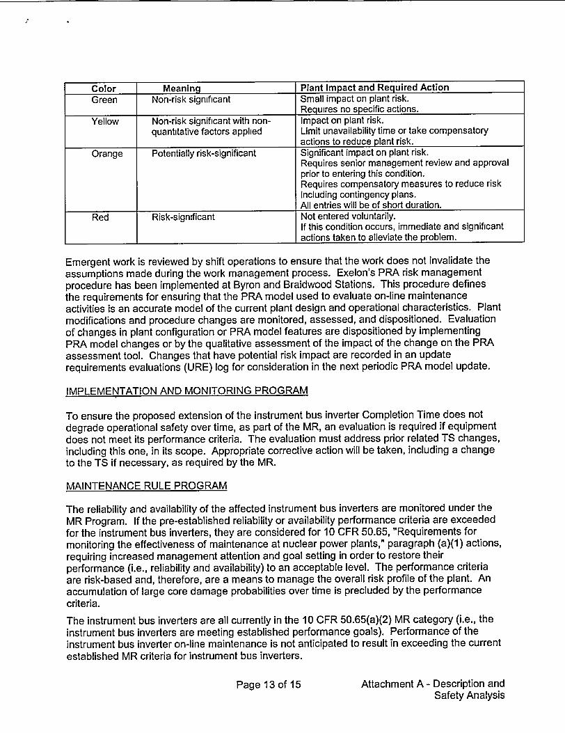
Color Meaning Plant Impact and Required Action Green Non-risk significant Small impact on plant risk.
Requires no specific actions. Yellow Non-risk significant with non- Impact on plant risk.
quantitative factors applied Limit unavailability time or take compensatory actions to reduce plant risk.
Orange Potentially risk-significant Significant impact on plant risk. Requires senior management review and approval prior to entering this condition. Requires compensatory measures to reduce risk including contingency plans. All entries will be of short duration.
Red Risk-significant Not entered voluntarily. If this condition occurs, immediate and significant actions taken to alleviate the problem.
Emergent work is reviewed by shift operations to ensure that the work does not invalidate the assumptions made during the work management process. Exelon's PRA risk management procedure has been implemented at Byron and Braidwood Stations. This procedure defines the requirements for ensuring that the PRA model used to evaluate on-line maintenance activities is an accurate model of the current plant design and operational characteristics. Plant modifications and procedure changes are monitored, assessed, and dispositioned. Evaluation of changes in plant configuration or PRA model features are dispositioned by implementing PRA model changes or by the qualitative assessment of the impact of the change on the PRA assessment tool. Changes that have potential risk impact are recorded in an update requirements evaluations (URE) log for consideration in the next periodic PRA model update.
IMPLEMENTATION AND MONITORING PROGRAM
To ensure the proposed extension of the instrument bus inverter Completion Time does not degrade operational safety over time, as part of the MR, an evaluation is required if equipment does not meet its performance criteria. The evaluation must address prior related TS changes, including this one, in its scope. Appropriate corrective action will be taken, including a change to the TS if necessary, as required by the MR.
MAINTENANCE RULE PROGRAM
The reliability and availability of the affected instrument bus inverters are monitored under the MR Program. If the pre-established reliability or availability performance criteria are exceeded for the instrument bus inverters, they are considered for 10 CFR 50.65, "Requirements for monitoring the effectiveness of maintenance at nuclear power plants," paragraph (a)(1) actions, requiring increased management attention and goal setting in order to restore their performance (i.e., reliability and availability) to an acceptable level. The performance criteria are risk-based and, therefore, are a means to manage the overall risk profile of the plant. An accumulation of large core damage probabilities over time is precluded by the performance criteria.
The instrument bus inverters are all currently in the 10 CFR 50.65(a)(2) MR category (i.e., the instrument bus inverters are meeting established performance goals). Performance of the instrument bus inverter on-line maintenance is not anticipated to result in exceeding the current established MR criteria for instrument bus inverters.
Page 13 of 15 Attachment A - Description and Safety Analysis

The actual instrument bus inverter reliability and availability will be monitored and periodically evaluated to assess the effect of the proposed extended Completion Time upon plant performance in relationship to the MR goals.
To ensure the TS Completion Time does not degrade operational safety over time, the MR Program will be used, as discussed above, to identify and correct adverse trends.
Compliance with the MR not only optimizes reliability and availability of important equipment, it also results in management of the risk when equipment is taken out of service for testing or maintenance per 10 CFR 50.65(a)(4).
Plant modifications and procedure changes are monitored, assessed and dispositioned. Evaluation of changes in plant configuration or PRA model features are dispositioned by implementing PRA model changes or by qualitatively assessing the impact of the changes on the CRMP assessment tool. Procedures exist for the control and application of CRMP assessment tools, and include a description of the process when the plant configuration of concern is outside the scope of the CRMP assessment tool.
CHANGE CONTROL
The CRMP is referenced and maintained as an administrative program in the Byron and Braidwood Stations TRMs. Changes to the TRM are subject to the requirements of 10 CFR 50.59, "Changes, Tests, and Experiments." The goals of a CRMP are to ensure that risksignificant plant configurations will not be inadvertently entered for planned maintenance activities, and appropriate actions will be taken should unforeseen events place the plant in a risk-significant configuration during the proposed extended instrument bus inverter Completion Time.
CONCLUSION
The proposed 14-day instrument bus inverter Completion Time is based upon both a deterministic evaluation and a risk-informed assessment. The risk assessment concluded that the increase in plant risk is small and consistent with the NRC "Safety Goals for the Operations of Nuclear Power Plants; Policy Statement," Federal Register, Vol.51, p.30028 (51 FR 30028), August 4, 1986, as interpreted by NRC Regulatory Guides 1.174 and 1.177. The deterministic evaluation consisted of two main elements: 1) the availability of ESF power to the 120V buses, and 2) implementation of a CRMP while the instrument bus inverter is in an extended Completion Time. The evaluation concluded that the proposed changes are consistent with the defense-in-depth philosophy and that sufficient safety margins are maintained. Together these analyses provide high assurance of the capability to provide power to the ESF buses to support instrument bus inverter reliability during the proposed 14-day instrument bus inverter Completion Time.
The proposed change results in a negligible increase in CDF and LERF, but the small increase in plant risk is consistent with the intent of the NRC Safety Goal Policy Statement. The impact of the proposed change will be monitored using performance measures to ensure actual reliability and availability is consistent with the values used in the PRA.
Page 14 of 15 Attachment A - Description and Safety Analysis

G. IMPACT ON PREVIOUS SUBMITTALS
We have reviewed the proposed change regarding its impact on any previous submittals and have determined that there is no impact on any previous submittals. However, consistent with RG 1.177, we have evaluated the potential impact on the previous risk-informed technical specification submittal on EDG Completion Times (i.e., Reference 2). As a result, the conclusions of the ICCDP/ICLERP evaluations for the EDG and instrument bus inverter are not impacted by their respective Completion Time extensions. The ACDF/ALERF calculations are also independent. Thus, the computed EDG Completion Time ACDF/ALERF previously submitted is representative. Since the ACDF/ALERF computed in this submittal for the instrument bus inverters is negligible, the additional risk increase from this change is negligible.
The other risk-informed submittal previously made for Byron and Braidwood Stations is the riskinformed ISI program improvement. Operating with an instrument bus inverter in maintenance for 14 days has no impact on the insights or conclusions from that analysis.
H. SCHEDULE REQUIREMENTS
We request approval of the proposed change by October 15, 2003.
I. REFERENCES
1. Regulatory Guide 1.177, "An Approach for Plant-Specific, Risk-Informed Decisionmaking: Technical Specifications," August 1998.
2. Letter from R. M. Krich (CoinEd) to U.S. NRC Document Control Desk, "Request for Amendment to Technical Specifications - Extension of Allowable Completion Times and Surveillance Requirement Change for Emergency Diesel Generators," January 20, 2000.
3. Regulatory Guide 1.174, "An Approach for Using Probabilistic Risk Assessment in RiskInformed Decisions on Plant-Specific Changes to the Licensing Basis," July 1998.
Page 15 of 15 Attachment A - Description and Safety Analysis

ATTACHMENT B-1
PROPOSED TS CHANGES FOR BRAIDWOOD STATION
MARKED-UP TS PAGES
3.8.7-1
Attachment B-1 - Braidwood Station Marked-Up TS Pages

Inverters - Operati ng 3.8.7
3.8 ELECTRICAL POWER SYSTEMS
3.8.7 Inverters -Operating
LCO 3.8.7
APPLICABILITY:
AflJ ThIS
Four instrument bus inverters shall be OPERABLE.
MODES 1, 2. 3, and 4.
CONDITION REQUIRED ACTION COMPLETION TIME
A. One instrument bus inverter inoperable.
A. 1 ---- NOTE Enter applicable Conditions and Required Actions of LCO 3.8.9, "Di stri buti on Systems - Operating" with any instrument bus de-energized.
Restore inverter to OPERABLE status.
B. Required Action and B.1 Be in MODE 3. 6 hours associated Completion Time not met. AND
B.2 Be in MODE 5. 36 hours
BRAIDWOOD - UNITS 1 & 2
24 hatfPscCitt)
Amendment"98.3.8.7-1

ATTACHMENT B-2
PROPOSED TS CHANGES FOR BYRON STATION
MARKED-UP TS PAGES
3.8.7-1
Attachment B-2 - Byron Station Marked-Up TS Pages

Inverters -Operating 3.8.7
3.8 ELECTRICAL POWER SYSTEMS
3.8.7 Inverters -Operating
LCO 3.8.7
APPLICABILITY:
ACTTnNK
Four instrument bus inverters shall be OPERABLE.
MODES 1. 2, 3, and 4.
CONDITION REQUIRED ACTION COMPLETION TIME
A. One instrument bus inverter inoperable.
A. 1 -- NOTEEnter applicable Conditions and Required Actions of LCO 3.8.9. "Di stri buti on Systems - Operating" with any instrument bus de-energized.
Restore inverter to OPERABLE status.
/1- d ys -24 heciG-
B. Required Action and B.1 Be in MODE 3. 6 hours associated Completion Time not met. AND
B.2 Be in MODE 5. 36 hours
Amendment lBYRON - UNITS 1 & 2 3.8.7-1

ATTACHMENT B-3
PROPOSED TS CHANGES INCORPORATED FOR BRAIDWOOD STATION
TS PAGES
3.8.7-1
Attachment B-3 - Braidwood Station Incorporated TS Pages

Inverters-Operating 3.8.7
3.8 ELECTRICAL POWER SYSTEMS
3.8.7 Inverters-Operating
LCO 3.8.7
APPLICABILITY:
Four instrument bus inverters shall be OPERABLE.
MODES 1, 2, 3, and 4.
ACTIONS
CONDITION REQUIRED ACTION COMPLETION TIME
A. One instrument bus A.1 -------- NOTE-----inverter inoperable. Enter applicable
Conditions and Required Actions of LCO 3.8.9, "Di stri buti on Systems-Operating" with any instrument bus de-energized.
Restore inverter to 14 days OPERABLE status.
B. Required Action and B.1 Be in MODE 3. 6 hours associated Completion Time not met. AND
B.2 Be in MODE 5. 36 hours I I
BRAIDWOOD - UNITS 1 & 2
I
Amendment3.8.7 - 1

ATTACHMENT B-4
PROPOSED TS CHANGES INCORPORATED FOR BYRON STATION
TS PAGES
3.8.7-1
Attachment B-4 - Byron Station Incorporated TS Pages

Inverters-Operati ng 3.8.7
3.8 ELECTRICAL POWER SYSTEMS
3.8.7 Inverters-Operating
LCO 3.8.7
APPLICABILITY:
Four instrument bus inverters shall be OPERABLE.
MODES 1, 2, 3, and 4.
ACTIONS
CONDITION REQUIRED ACTION COMPLETION TIME
A. One instrument bus A.1 -------- NOTE-----inverter inoperable. Enter applicable
Conditions and Required Actions of LCO 3.8.9, "Distribution Systems - Operating" with any instrument bus de-energized.
Restore inverter to 14 days OPERABLE status.
B. Required Action and B.1 Be in MODE 3. 6 hours associated Compl eti on Time not met. AND
B.2 Be in MODE 5. 36 hours
AmendmentBYRON - UNITS 1 & 2
I
3.8.7 - 1

ATTACHMENT B-5
PROPOSED TS BASES CHANGES INCORPORATED FOR BRAIDWOOD STATION FOR INFORMATION ONLY
TS BASES PAGES
B 3.8.7-3
Attachment B-5 - Braidwood Station Incorporated TS Bases Pages
Inverters-Operati ng B 3.8.7
BASES
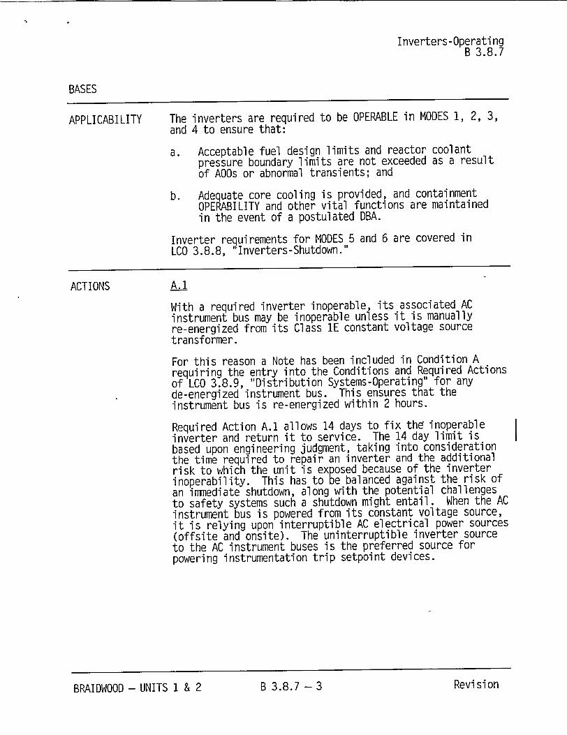
APPLICABILITY The inverters are required to be OPERABLE in MODES 1, 2, 3, and 4 to ensure that:
a. Acceptable fuel design limits and reactor coolant pressure boundary limits are not exceeded as a result of AOOs or abnormal transients; and
b. Adequate core cooling is provided, and containment OPERABILITY and other vital functions are maintained in the event of a postulated DBA.
Inverter requirements for MODES 5 and 6 are covered in LCO 3.8.8, Inverters-Shutdown."
ACTIONS A.1
With a required inverter inoperable, its associated AC instrument bus may be inoperable unless it is manually re-energized from its Class 1E constant voltage source transformer.
For this reason a Note has been included in Condition A requiring the entry into the Conditions and Required Actions of LCO 3.8.9, "Distribution Systems-Operating" for any de-energized instrument bus. This ensures that the instrument bus is re-energized within 2 hours.
Required Action A.1 allows 14 days to fix th• inoperable inverter and return it to service. The 14 day limit is based upon engineering judgment, taking into consideration the time required to repair an inverter and the additional risk to which the unit is exposed because of the inverter inoperability. This has to be balanced against the risk of an immediate shutdown, along with the potential challenges to safety systems such a shutdown might entail. When the AC instrument bus is powered from its constant voltage source, it is relying upon interruptible AC electrical power sources (offsite and onsite). The uninterruptible inverter source to the AC instrument buses is the preferred source for powering instrumentation trip setpoint devices.
Revi si onBRAIDWOOD - UNITS 1 & 2 B 3.8.7- 3
ATTACHMENT B-6
PROPOSED TS BASES CHANGES INCORPORATED FOR BYRON STATION FOR INFORMATION ONLY
TS BASES PAGES
B 3.8.7-3
Attachment B-6 - Byron Station Incorporated TS Bases Pages
Inverters-Operating
B 3.8.7
BASES
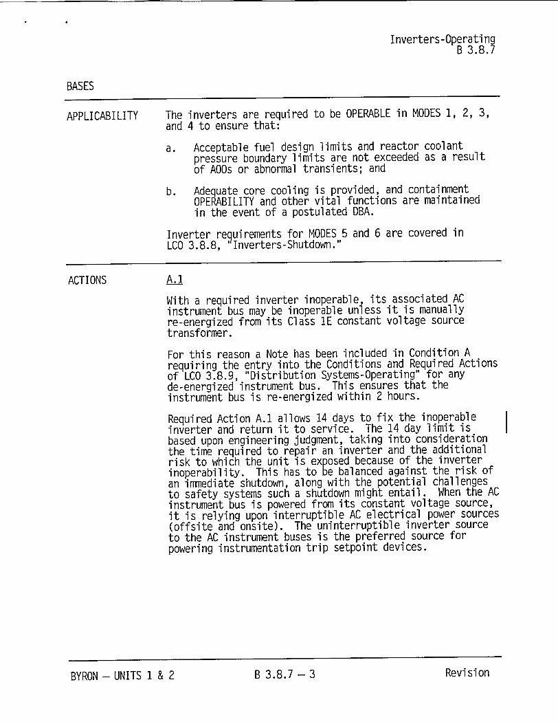
APPLICABILITY The inverters are required to be OPERABLE in MODES 1, 2, 3, and 4 to ensure that:
a. Acceptable fuel design limits and reactor coolant pressure boundary limits are not exceeded as a result of AOOs or abnormal transients; and
b. Adequate core cooling is provided, and containment OPERABILITY and other vital functions are maintained in the event of a postulated DBA.
Inverter requirements for MODES 5 and 6 are covered in LCO 3.8.8, "Inverters-Shutdown."
ACTIONS A.1
With a required inverter inoperable, its associated AC instrument bus may be inoperable unless it is manually re-energized from its Class 1E constant voltage source transformer.
For this reason a Note has been included in Condition A requiring the entry into the Conditions and Required Actions of LCO 3.8.9, "Distribution Systems-Operating" for any de-energized instrument bus. This ensures that the instrument bus is re-energized within 2 hours.
Required Action A.1 allows 14 days to fix the inoperable inverter and return it to service. The 14 day limit is based upon engineering judgment, taking into consideration the time required to repair an inverter and the additional risk to which the unit is exposed because of the inverter inoperability. This has to be balanced against the risk of an immediate shutdown, along with the potential challenges to safety systems such a shutdown might entail. When the AC instrument bus is powered from its constant voltage source, it is relying upon interruptible AC electrical power sources (offsite and onsite). The uninterruptible inverter source to the AC instrument buses is the preferred source for powering instrumentation trip setpoint devices.
BYRON - UNITS 1 & 2 B 3.8.7 - 3 RevisionB 3.8.7- 3 Revi si onBYRON - UNITS 1 & 2

ATTACHMENT C
INFORMATION SUPPORTING A FINDING OF NO SIGNIFICANT HAZARDS CONSIDERATION
According to 10 CFR 50.92(c), "Issuance of amendment," a proposed amendment to an operating license involves no significant hazards consideration if operation of the facility in accordance with the proposed amendment would not:
(1) Involve a significant increase in the probability or consequences of an accident previously evaluated; or
(2) Create the possibility of a new or different kind of accident from any accident previously evaluated; or
(3) Involve a significant reduction in a margin of safety.
In accordance with 10 CFR 50.90, "Application for amendment of license or construction permit," Exelon Generation Company, LLC (Exelon) is proposing a change to the Technical Specifications (TS) of Facility Operating License Nos. NPF-72, NPF-77, NPF-37 and NPF-66, for the Braidwood Station, Units 1 and 2, and the Byron Station, Units 1 and 2, respectively. The proposed change revises the Completion Time for Required Action A.1 of TS 3.8.7, "Inverters - Operating," from the current 24 hours for one instrument bus inverter inoperable to 14 days. The change is being proposed to support on-line maintenance of the instrument bus inverters. The current Completion Time for restoration of an inoperable instrument bus inverter is insufficient to support the required maintenance and post-maintenance testing windows. Implementation of this proposed Completion Time extension would provide the following benefits: (1) Allow increased flexibility in the scheduling and performance of preventive maintenance. Allowing on-line preventive maintenance provides the flexibility to focus quality resources on any required or elective instrument bus inverter maintenance; (2) Avert unplanned plant shutdowns and minimize the potential need for requests for Notice of Enforcement Discretion (NOED). Risks incurred by unexpected plant shutdowns can be comparable to and often exceed those associated with continued power operation; and (3) Improve instrument bus inverter availability during shutdown modes or conditions.
Information supporting the determination that the criteria set forth in 10 CFR 50.92 are met for this amendment request is indicated below.
1. Does the proposed change involve a significant increase in the probability or consequences of an accident previously evaluated?
The proposed action allows continued unit operation, for up to 14 days, with an inoperable instrument bus inverter. An inoperable instrument bus inverter is not considered as an initiator of any analyzed event. Extending the Completion Time for an inoperable instrument bus inverter would not have a significant impact on the frequency of occurrence for any accident previously evaluated. The proposed change will not result in changes to the plant activities associated with instrument bus inverter maintenance, but rather will allow increased flexibility in the scheduling and performance of preventive maintenance. Therefore, this change will not
Page 1 of 3 Attachment C - Significant Hazards Consideration
significantly increase the probability of occurrence of any event previously analyzed in the current Byron/Braidwood Stations' Updated Final Safety Analysis Report (UFSAR) safety analyses.
The consequences of a previously analyzed event are dependent on the initial conditions assumed in the analysis, the availability and successful functioning of equipment assumed to operate in response to the analyzed event, and the setpoints at which these actions are initiated. With an instrument bus inverter inoperable, the affected instrument bus is capable of being fed from its dedicated safety-related constant voltage transformer (CVT), which is powered from a 480 VAC Engineered Safety Feature (ESF) bus. In the event of a Loss of Offsite Power (LOOP), the affected instrument bus will experience a momentary loss of power until the associated diesel generator (DG) re-energizes the 480 VAC ESF bus. A LOOP with an inoperable instrument bus inverter (i.e., instrument bus being powered by its CVT) will result in a loss of power to the associated instrument bus until the associated DG re-energizes the 480 VAC ESF bus. All instruments supplied by the instrument bus would be restored with no adverse impact to the units because no other instrument channels in the opposite train would be expected to be inoperable or in a tripped condition during this time, with the exception of routine surveillances. In the event the DG failed (i.e., failed to re-energize the 480 VAC ESF bus), power could still be established to the 4 kV ESF bus by powering the 480 VAC ESF bus from the opposite unit 4 kV ESF bus cross-tie breaker. In the event of a failure to re-energize the 480 VAC ESF bus or of a CVT failure, the most significant impact on the unit is the failure of one train of ESF equipment to actuate. In this condition, the redundant train of ESF equipment will automatically actuate to mitigate the accident, and the affected unit would remain within the bounds of the accident analyses. Therefore, the request for extending the Completion Time will not significantly increase the consequences of an accident previously evaluated in the Byron/Braidwood Stations' UFSAR.
2. Does the proposed change create the possibility of a new or different kind of accident from any accident previously evaluated?
The proposed action does not involve physical alteration of the station. No new equipment is being introduced, and installed equipment is not being operated in a new or different manner. There is no change being made to the parameters within which the units are operated. There are no setpoints at which protective or mitigative actions are initiated that are affected by this proposed action. The use of the CVT as an alternate power source for the instrument bus is
consistent with the Byron and Braidwood Stations' plant designs. This proposed action will not alter the manner in which equipment operation is initiated, nor will the function demands on credited equipment be changed. No alteration in the procedures, which ensure the unit remains within analyzed limits, is proposed, and no change is being made to procedures relied upon to respond to an off-normal event. As such, no new failure modes are being introduced. The proposed action does not alter assumptions made in the safety analysis.
Therefore, the proposed change does not create the possibility of a new or different kind of accident from any accident previously evaluated.
Page 2 of 3 Attachment C - Significant Hazards Consideration

3. Does the proposed change involve a significant reduction in a margin of safety?
Margins of safety are established in the design of components, the configuration of components to meet certain performance parameters, and in the establishment of setpoints to initiate alarms or actions. There is no change in the design of the affected systems, no alteration of the setpoints at which alarms or actions are initiated, and no change in plant configuration from original design. With one of the required instrument buses being powered from the CVT, there is no significant reduction in the margin of safety. Testing of the DGs and associated electrical distribution equipment provides confidence that the DGs will start and provide power to the associated equipment in the unlikely event of a LOOP during the extended 14-day Completion Time.
Therefore, the proposed change does not involve a significant reduction in a margin of safety.
Based on the above evaluation, we have concluded that the proposed change does not involve a significant hazards consideration.
Page 3 of 3 Attachment C - Significant Hazards Consideration
ATTACHMENT D
INFORMATION SUPPORTING AN ENVIRONMENTAL ASSESSMENT
In accordance with 10 CFR 50.90, "Application for amendment of license or construction permit," Exelon Generation Company, LLC (Exelon) is proposing a change to the Technical Specifications (TS) of Facility Operating License Nos. NPF-72, NPF-77, NPF-37 and NPF-66, for the Braidwood Station, Units 1 and 2, and the Byron Station, Units 1 and 2, respectively. The proposed change revises the Completion Time for Required Action A.1 of TS 3.8.7, "Inverters - Operating," from the current 24 hours for one instrument bus inverter inoperable to 14 days. The change is being proposed to support on-line maintenance of the instrument bus inverters. The current Completion Time for restoration of an inoperable instrument bus inverter is insufficient to support the required maintenance and post-maintenance testing windows. Implementation of this proposed Completion Time extension would provide the following benefits: (1) Allow increased flexibility in the scheduling and performance of preventive maintenance. Allowing on-line preventive maintenance provides the flexibility to focus quality resources on any required or elective instrument bus inverter maintenance; (2) Avert unplanned plant shutdowns and minimize the potential need for requests for Notice of Enforcement Discretion (NOED). Risks incurred by unexpected plant shutdowns can be comparable to and often exceed those associated with continued power operation; and (3) Improve instrument bus inverter availability during shutdown modes or conditions.
Exelon has evaluated the proposed change against the criteria for identification of licensing and regulatory actions requiring environmental assessment in accordance with 10 CFR 51.21, "Criteria for and identification of licensing and regulatory actions requiring environmental assessments." Exelon has determined that the proposed change meets the criteria for a categorical exclusion set forth in 10 CFR 51.22(c)(9), "Criteria for categorical exclusion; identification of licensing and regulatory actions eligible for categorical exclusion or otherwise not requiring environmental review," and as such, has determined that no irreversible consequences exist in accordance with 10 CFR 50.92(b), "Issuance of amendment." This determination is based on the fact that this change is being proposed as an amendment to a license issued pursuant to 10 CFR 50, "Domestic Licensing of Production and Utilization Facilities," which changes a requirement with respect to
installation or use of a facility component located within the restricted area, as defined in 10 CFR 20, "Standards for Protection Against Radiation," or which changes an inspection or a surveillance requirement, and the amendment meets the following specific criteria.
(i) The proposed change involves no significant hazards consideration.
As demonstrated in Attachment C, the proposed change does not involve any significant hazards consideration.
(ii) There is no significant change in the types or significant increase in the amounts of any effluents that may be released offsite.
The proposed change does not allow for an increase in the unit power level, does not increase the production, nor alter the flow path or method of disposal of radioactive waste or by-products. The proposed change does not affect actual unit effluents. Therefore, the proposed change does not change the types or increase the amounts of any effluents released offsite.
Page 1 of 2 Attachment D - Environmental Assessment

(iii) There is no significant increase in individual or cumulative occupational radiation exposure.
The proposed change will not result in changes in the operation or configuration of the facility. There will be no change in the level of controls or methodology used for processing of radioactive effluents or handling of solid radioactive waste, nor will the proposal result in any change in the normal radiation levels within the plant. Therefore, there will be no increase in individual or cumulative occupational radiation exposure resulting from the proposed change.
Page 2 of 2 Attachment D - Environmental Assessment
ATTACHMENT E
SUMMARY OF THE BYRON AND BRAIDWOOD STATION PROBABILISTIC RISK ASSESSMENT
1.0 Background
The Byron and Braidwood Stations Individual Plant Examinations (IPEs) were submitted to the NRC by letters dated April 28,1994 and June 30, 1994, respectively, in response to Generic Letter (GL) 88-20, "Individual Plant Examination for Severe Accident Vulnerabilities - 10 CFR 50.54(f)." Requests for Additional Information (RAIs) were sent to Exelon (formerly Commonwealth Edison (CoinEd) Company) by the NRC on January 26, 1996 for Braidwood Station and February 1, 1996 for Byron Station. The requests identified concerns that were similar to those raised previously by the NRC for the Zion Nuclear Power Station IPE. As a result of the RAIs, Modified IPEs were developed for the Byron and Braidwood Stations and submitted to the NRC on March 27,1997. The Modified IPEs included the 4 kV ESF bus crosstie procedure enhancements discussed in thb original IPEs. The NRC approved the Modified IPEs by letters dated December 3, 1997 for Byron Station and October 27, 1997 for Braidwood Station. The NRC letters noted that the Modified IPE submittals met the intent of Generic Letter 88-20. The current Byron and Braidwood Stations Probabilistic Risk Assessments (PRAs) were prepared by major upgrades and updates of the previous update. The following section highlights changes to the Modified IPEs made during the development of the PRA upgrades.
2.0 Changes to the PRA Model
An overview of the upgrades that have been made to the Braidwood and Byron Stations' PRAs since the Emergency Diesel Generator (EDG) Completion Time extension request was submitted is provided in Table E2-1, "Summary of Major Changes in Current PRA Models for Braidwood and Byron Stations." Some of the more significant enhancements are discussed below.
2.1 Event Trees
The following event trees are represented in the Byron and Braidwood Stations PRAs.
General Transient Loss of a Direct Current (DC) Bus Transient Event Tree Anticipated Transients Without Scram (ATWS) Secondary Line Break Inside Containment Secondary Line Break Outside Containment Single Unit and Dual Unit Loss of Offsite Power (LOOP, DLOOP) Steam Generator Tube Rupture (SGTR) Excessive LOCA (i.e., vessel rupture) (XLOCA) Large Break LOCA (LLOCA) Medium Break LOCA (MLOCA) Small Break LOCA, Isolable and Non-Isolable (SLOCA) Interfacing Systems LOCA Outside Containment (ISLOCA)
The XLOCA and ISLOCA event trees are mapped directly to core damage.
Page 1 of 8 Attachment E Probabilistic Risk Assessment

Table E2-1 Summary of Major Changes in Current PRA Models for Braidwood and Byron Stations
PRA Elements Summary of Major Changes Initiating Events Added three internal flooding initiating events to model. Analysis Deleted loss of 120V bus initiators based on plant experience.
Revised CCW (i.e., component cooling water) initiating event treatment.
Event Sequence Expanded LOOP/DLOOP event tree. Modeling Removed credit for condensate feedwater as a means of
secondary heat removal. Revised the event tree modeling to credit startup feedwater (using main feedwater pumps) as a means of secondary cooling when no high head emergency core cooling system (ECCS) injection is available.
Success Criteria and Modified SX (i.e., essential service water) pump success criteria Thermal Hydraulic to credit one of four pumps supporting both units. Analysis Systems Analysis Incorporated plant modification to allow CV pump (i.e., centrifugal
charging pump) cooling via FP (i.e., fire protection). Incorporated detailed RPS (i.e., reactor protection system) and ESFAS (i.e., engineered safety feature actuation system) models. Revised CCW model to reflect operational modes. Miscellaneous enhancements.
Common Cause Added inverter common cause and included some additional Analysis motor operated valve common cause events (i.e., for 8804NB,
CC 9412A/B). Human Reliability Updated selected human error probabilities (HEPs) based on Analysis operator interviews.
Added internal flood human actions. Data Analysis Incorporated plant-specific inverter failure rates. Internal Flooding Developed plant-specific pipe break frequencies for SX, WS Analysis (non-essential service water), and FP.
Detailed assessment of auxiliary building impacts. Human reliability analysis (HRA) updated.
Level 2 LERF Updated evaluation of high pressure melt ejection (HPME) impacts.
3.0 PRA Baseline Results for Core Damage Frequency (CDF)
The current baseline PRA results for each unit at the Braidwood and Byron Stations are compared with the previous results for each station in Table E3-1, "Summary of Mean CDF Baseline PRA Results for Braidwood and Byron Station." The results show a significant decrease for the Braidwood units and a moderate increase at the Byron units. The Braidwood reduction in CDF is a result of the incorporation of the plant modification made to provide alternate cooling to the centrifugal charging pumps lube oil heat exchanger via the FP system. In Revision 0 of the Braidwood Station PRA, CDF was dominated by loss of SX cooling water events. The Byron Station results increased because at Byron the decrease in loss of SX CDF sequences was offset by increased CDF from other scenarios, primarily due to inclusion of
Page 2 of 8 Attachment E Probabilistic Risk Assessment
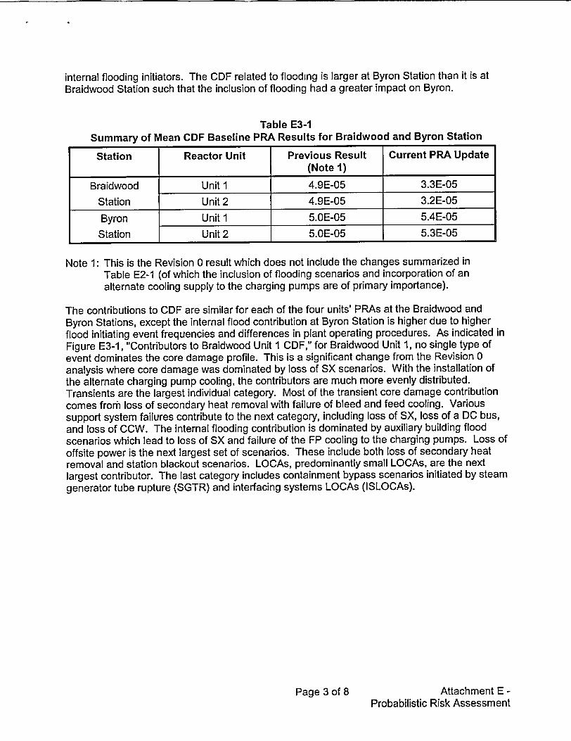
internal flooding initiators. The CDF related to flooding is larger at Byron Station than it is at Braidwood Station such that the inclusion of flooding had a greater impact on Byron.
Table E3-1 Summary of Mean CDF Baseline PRA Results for Braidwood and Byron Station
Station Reactor Unit Previous Result Current PRA Update (Note 1)
Braidwood Unit 1 4.9E-05 3.3E-05
Station Unit 2 4.9E-05 3.2E-05
Byron Unit 1 5.OE-05 5.4E-05
Station Unit 2 5.OE-05 5.3E-05
Note 1: This is the Revision 0 result which does not include the changes summarized in Table E2-1 (of which the inclusion of flooding scenarios and incorporation of an alternate cooling supply to the charging pumps are of primary importance).
The contributions to CDF are similar for each of the four units' PRAs at the Braidwood and Byron Stations, except the internal flood contribution at Byron Station is higher due to higher flood initiating event frequencies and differences in plant operating procedures. As indicated in Figure E3-1, "Contributors to Braidwood Unit 1 CDF," for Braidwood Unit 1, no single type of event dominates the core damage profile. This is a significant change from the Revision 0 analysis where core damage was dominated by loss of SX scenarios. With the installation of the alternate charging pump cooling, the contributors are much more evenly distributed. Transients are the largest individual category. Most of the transient core damage contribution comes frorfi loss of secondary heat removal with failure of bleed and feed cooling. Various support system failures contribute to the next category, including loss of SX, loss of a DC bus, and loss of CCW. The internal flooding contribution is dominated by auxiliary building flood scenarios which lead to loss of SX and failure of the FP cooling to the charging pumps. Loss of offsite power is the next largest set of scenarios. These include both loss of secondary heat removal and station blackout scenarios. LOCAs, predominantly small LOCAs, are the next largest contributor. The last category includes containment bypass scenarios initiated by steam generator tube rupture (SGTR) and interfacing systems LOCAs (ISLOCAs).
Page 3 of 8 Attachment E Probabilistic Risk Assessment
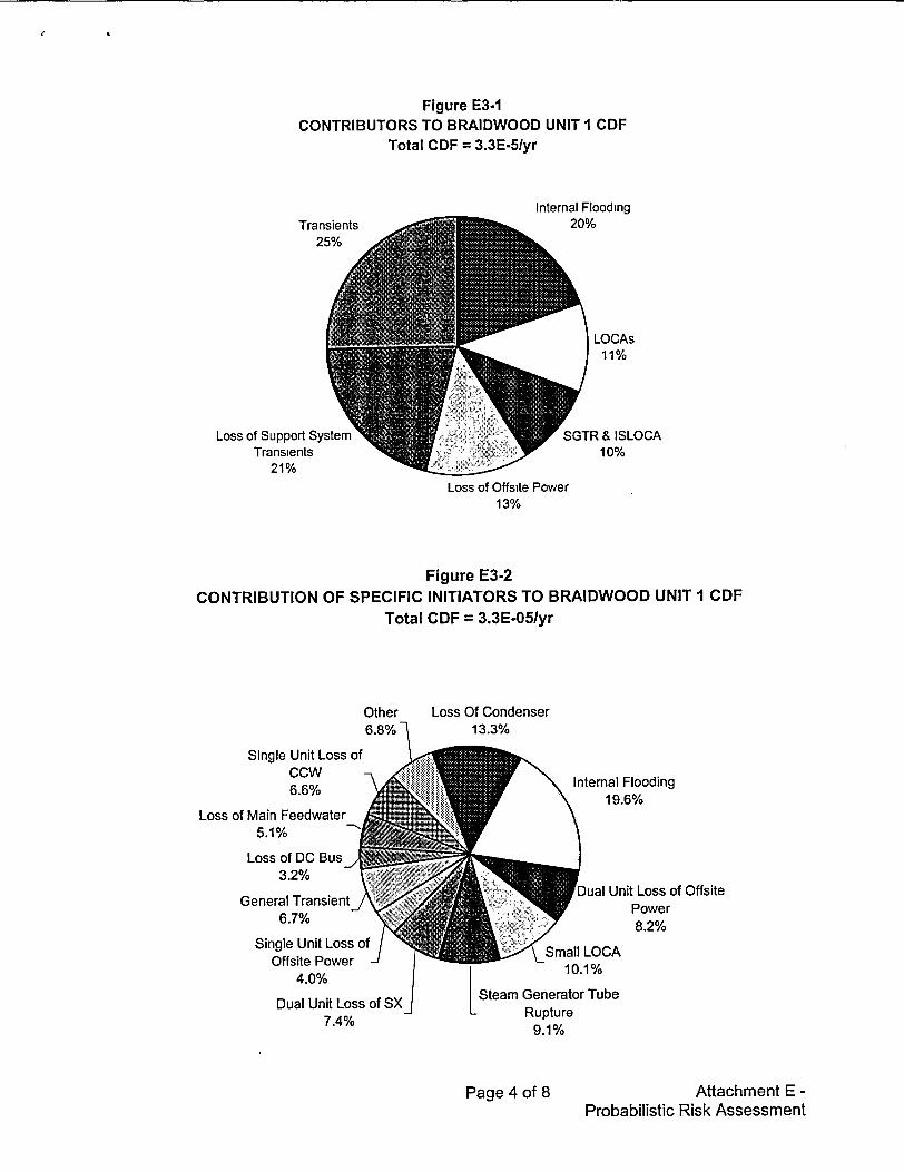
Figure E3-1 CONTRIBUTORS TO BRAIDWOOD UNIT I CDF
Total CDF = 3.3E-5/yr
Transients 25%
Loss of Support System Transients
21%
Internal Flooding 20%
LOCAs 11%
SGTR &ISLOCA 10%
Loss of Offsite Power 13%
Figure E3-2
CONTRIBUTION OF SPECIFIC INITIATORS TO BRAIDWOOD UNIT I CDF Total CDF = 3.3E-05/yr
Other 6.8%j
Loss Of Condenser 13.3%
Single Unit Loss of CCW
6.6%
Loss of Main Feedwater 5.1%
Loss of DC Bus-/ 3.2%
General Transient 6.7%
Single Unit Loss of Offsite Power
4.0%
Dual Unit Loss of SX 7.4%
Internal Flooding 19.6%
Dual Unit Loss of Offsite Power 8.2%
<Small LOCA 10.1%
Steam Generator Tube Rupture
9.1%
Page 4 of 8 Attachment E Probabilistic Risk Assessment

The contributions to CDF from specific initiating events at Braidwood Station, Unit 1 are depicted in Figure E3-2, "Contribution of Specific Initiators to Braidwood Unit lCDF." The single largest initiating event is internal flooding initiators. The next largest is a transient, i.e., loss of condenser. The dominant core damage scenarios for loss of condenser are due to the initiator leading to loss of main feedwater, followed by failure of both auxiliary feedwater (AFW) pumps and various failures of bleed and feed cooling. LOOP events have been delineated to distinguish between events that impact both units concurrently and each unit separately. These events contribute roughly 8% and 4%, respectively. The most important initiating events that involve loss of primary system coolant are small break LOCAs (10%) and SGTRs (9%). Loss of SX, loss of CCW, and losses of individual DC buses are the largest loss of support system initiators. Rounding out the top contributors are two other transient events, the general transient category and loss of main feedwater.
Table E3-2, "CDF Contribution by Initiating Event," provides a tabulation of the CDF contribution by initiating event for Byron Station, Units 1 and 2, and Braidwood Station, Units 1 and 2, in the upgraded PRAs. This table shows that, while there are differences between the respective risk profiles, the general character of the profiles illustrated in Figures E3-1 and E3-2 are the same at both stations.
Table E3-2 CDF Contribution by Initiating Event
Page 5 of 8 Attachment E Probabilistic Risk Assessment
Core Damaqe Frequency Uyear)Braidwood Braidwood Byron Byron
Initiating Event Unit 1 Unit 2 Unit I Unit 2
Transients Loss of Condenser Heat Sink 4.3E-06 4.3E-06 4.2E-06 4.2E-06 General Transient Initiating Event 2.2E-06 2.2E-06 3.3E-06 2.8E-06 Loss of Main Feedwater 1.7E-06 1.7E-06 3.1E-06 3.OE-06 Feedline Break Inside Containment 2.2E-08 2.2E-08 3.4E-08 3.4E-08 Steamline Break Inside Containment 2.2E-08 2.2E-08 3.4E-08 3.4E-08 Steamline Break Outside Containment 9.9E-09 9.9E-09 1.1E-08 1.1 E-08
Lossý ofOffsite Power (LOOP) Dual Unit LOOP (Sustained) 2.7E-06 2.7E-06 2.6E-06 2.6E-06 Dual Unit LOOP (Momentary) 1.9E-07 1.9E-07 4.7E-07 4.6E-07 Single Unit LOOP (Sustained) 1.3E-06 1.3E-06 1.2E-06 9.9E-07 Single Unit LOOP (Momentary) 6.6E-08 6.5E-08 8.8E-08 8.7E-08 Internal FloodingFP Flood 3.3E-06 3.3E-06 1.1 E-05 1.1 E-05 SX Flood 2.OE-06 2.OE-06 3.9E-06 4.OE-06 WS Flood 1.OE-06 1.0E-06 6.5E-06 6.5E-06
Loss of Support'System _____ ____
Dual Unit Loss of SX (Non Recoverable 2.4E-06 2.3E-06 3.6E-06 3.6E-06 Active Failures) Dual Unit Loss of SX (Recoverable Active 3.OE-1 0 3.OE-1 0 2.9E-1 0 2.9E-1 0 Failures) Unit 1 Loss of SX 5.6E-08 4.8E-08 5.6E-08 5.3E-08 (Non-Recoverable) Unit 1 Loss of SX 4.9E-10 4.9E-10 2.1 E-09 1.8E-09 (Recoverable)

(�nrc1 fl�m�n� FrAnImnr�v (Iv��ri
Braidwood Braidwood Byron Byron Initiating Event Unit I Unit 2 Unit I Unit 2
Loss of DC Bus 111 1.OE-06 1.OE-06 1.1E-06 1.1E-06 Loss of DC Bus 112 1.OE-08 1.OE-08 1.7E-08 1.5E-08 Loss of CCW 2.2E-06 2.2E-06 1.9E-06 1.9E-06 Dual Unit Loss Of CCW 1.2E-07 1.2E-07 4.5E-08 4.5E-08 Loss of CCW to Reactor Coolant Pumps 3.4E-07 3.3E-07 2.9E-07 2.9E-07 Loss of Instrument Air 3.5E-07 3.5E-07 7.9E-07 7.9E-07 Loss of WS 3.2E-07 3.2E-07 2.2E-06 2.1E-06 LOCAs" Small LOCA (Non-Isolable) 3.3E-06 3.3E-06 3.3E-06 3.3E-06 Small LOCA (Isolable) 3.OE-08 3.OE-08 2.9E-08 2.9E-08 Medium LOCA 1.7E-08 1.7E-08 1.8E-08 1.8E-08 Large LOCA 1.3E-08 1.3E-08 1.4E-08 1.4E-08 Excessive LOCA (Reactor Vessel 2.7E-07 2.7E-07 2.7E-07 2.7E-07 Rupture) SGTR& ISLOCA(Containment Bypass) SGTR 3.OE-06 2.9E-06 3.1E-06 3.1 E-06 Interfacing Systems LOCA 4.1E-07 4.1E-07 4.1E-07 4.1E-07 Total: 3.3E-05 3.2E-05 5.4E-05 5.3E-05
4.0 Evaluation of Large Early Release Frequency (LERF)
As part of the current Byron and Braidwood Stations' PRAs, a simplified LERF analysis was performed in accordance with NUREG/CR-6595, "An Approach for Estimating the Frequencies of Various Containment Failure Modes and Bypass Events." This analysis was used to evaluate the impacts of the proposed increase in instrument bus inverter Completion Time on annual average LERF and to evaluate the Incremental Conditional Large Early Release Probability (ICLERP) for comparison against the risk significance criteria in Regulatory Guide (RG) 1.174 "An Approach for Using Probabilistic Risk Assessment in Risk-Informed Decisions on Plant-Specific Changes to the Licensing Basis," and RG 1.177, "An Approach for PlantSpecific, Risk-Informed Decisionmaking: Technical Specifications."
This approach captures the plant-specific factors associated with active systems whose failures contribute to LERF such as containment isolation and bypass, and the frequency of severe accident challenges of the containment. These aspects of the LERF analysis are as realistic as the Level 1 Probabilistic Safety Analysis (PSA) for CDF determination. There are other aspects of this simplified approach that provide a rather conservative treatment of the phenomenological issues that contribute to LERF such as high pressure melt ejection, direct containment heating, and thermal creep rupture of reactor coolant system (RCS) components and the steam generator tubes. Hence, these LERF results should be regarded as conservative estimates in relation to the CDF results.
The results of the LERF quantification for each unit at Byron and Braidwood Stations are shown in Table E4-1, "LERF Results for Byron and Braidwood Stations," and Figure E4-1, "Contributors to LERF."
Page 6 of 8 Attachment E Probabilistic Risk Assessment
21

Table E4-1 LERF Results for Byron and Braidwood Stations
Braidwood Station Byron Station
LERF Contribution Unit I Unit 2 Unit 1 Unit 2
SGTR 3.OE-06 3.OE-06 3.2E-06 3.1 E-06
ISLOCA 4.1E-07 4.1E-07 4.1 E-07 4.1 E-07
Containment Overpressurization 3.OE-07 5.9E-07 7.2E-07 1.4E-06
Induced SGTR 6.9E-08 6.9E-08 6.OE-08 6.0E-08
Containment Isolation Failure 2.5E-07 2.6E-07 4.6E-07 4.7E-07
Total LERF 4.1 E-06 4.3E-06 4.8E-06 5.5E-06
These results are all within the criteria for risk significance in Section 2.2.4 of RG 1.174 and are consistent with results from other pressurized water reactors (PWRs) with large, dry containments. In reviewing these results, the following conservative aspects of the LERF evaluation should be kept in mind.
The simplified nature of the NUREG/CR-6595 methodology provides a conservative evaluation of containment failure from severe accident phenomena. It is expected that if a more realistic treatment of the above issues were performed, the above estimates of LERF would be significantly reduced. However, this LERF analysis is sufficient to support evaluation of the risk significance of the requested increase in the instrument bus inverter Completion Time, as many of the conservative assumptions, while affecting the baseline LERF values, do not impact the change in risk metrics associated with the requested increased Completion Time.
The relative contribution to LERF from the various containment failure modes/bypasses is illustrated in Figure E4-1. The majority (i.e., approximately two-thirds) of LERF occurs as the result of accident sequences that involve containment bypass (i.e., SGTRs and ISLOCAs). The largest phenomenological contributor is containment overpressurization, contributing roughly 8-25%. The containment overpressurization contributes more for Unit 2 at each site due to some electrical penetrations that have a lower ultimate pressure capability. This was identified in the IPE, but had not shown up in the previous LERF analysis because the NUREG/CR-6595 screening values for containment overpressurization were used. When a plant-specific analysis was developed as part of the recent update, it was determined that the conditional probability of a high pressure vessel rupture failing the Unit 2 containment was roughly twice the Unit 1 value (i.e., 0.05 vs. 0.025). Overall, the Byron Station containment overpressurization contribution is higher than for Braidwood Station. This is due to the higher core damage contribution from internal flooding that produces high pressure vessel failure scenarios. Containment isolation failures contribute roughly 7-10%. Induced SGTRs that occur during the core melt progression contribute less than 2%. As noted above, this contribution to LERF is viewed as conservative and driven by conservative assumptions in the NUREG/CR-6595 methodology in the treatment of severe accident phenomena.
Page 7 of 8 Attachment E Probabilistic Risk Assessment

In summary, the LERF results for Byron and Braidwood Stations are considered reasonable and exhibit some conservatism in the treatment of severe accident phenomena and in the omission of many operator actions and accident management strategies that would be expected to reduce the LERF contribution but were omitted from this LERF evaluation.
100%
90%
80%L. Wu 70%
-1
0 - 60%z
0 i-- 50%
cZ 40% I-z o 30%
20%
10%
0%
CONTAINMENT FAILURE MODE
0 Containment Isolation Failure
M Induced SGTR
M Containment Overpressurization
M ISLOCA
OSGTR
Figure E4-1 CONTRIBUTORS TO LE
Braidwood 2 Byron I
PLANT UNIT
Page 8 ofI
Braidwood I Byron 2
3 Attachment E Probabilistic Risk Assessment