brake motors ffb - leroy-somer · 3 en contents ffb brake motors maintenance guide 5287 en -...
TRANSCRIPT

2019.07 / d
en
Maintenance Guide
Reference: 5287 en -
Maintenance Guide
Brake motorsFFB

2
FFB Brake Motors Maintenance Guide5287 en - 2019.07 / d
GENERAL WARNING
This document is an addition to the general manual ref. 1889 (recommendations), ref. 4850 (LSES motor), ref. 4155 (LSRPM motor), and the installation manual ref. 5286.
FFB brake motors are assemblies made of an asynchronous motor and a failsafe braking system (safety brake).This brake motor benefits from the experience of a global manufacturer, using cutting edge technologies - automation, selected materials, thorough quality control - in our motor plants who have been awarded the ISO 9001 - Issue 2008 international certification.
These symbols appear in this document whenever it is important to take special precautions during installation, operation, maintenance or servicing of the brake motors.
It is prohibited to drive the extension shaft and the fan in manual rotation with the parking brake applied, or the brake released under load.
General danger Electrical hazard Risk of physical injury Risk of severe or lethal injury Risk of severe or lethal injury
These recommendations, instructions and descriptions refer to standard use. They do not take account of non-standard versions or special adaptations. Failure to comply with these recommendations can lead to premature wear and tear of the motor and can invalidate the manufacturer warranty. Make sure that the brake motor is compatible with its environment before its installation and also throughout its life.
The following preliminary precautions must be taken before working on any stationary device:• Mains voltage disconnected and no residual voltage present• Careful examination of the causes of the stoppage (blocked transmission - loss of phase - cut-out due to thermal protection - lack of lubrication, etc.)
Electric brake motors are industrial products. They must therefore be installed by qualified, experienced and authorized personnel. The safety of people, animals and property must be ensured when fitting the motors into machines (please refer to current standards). Particular attention must be given to equipotential ground or earthing connections.
Safety of personnel: protect all rotating devices before power-up. If a brake motor is started up without a coupling device having been fitted, carefully immobilize the key in its location. All measures must be taken to ensure protection against the risks which arise when there are rotating parts (coupling sleeve, pulley, belt, fan, etc.). Personal protective equipment must be worn. After work is carried out, the lids of the terminal box and its cover must always be closed.
Beware of backdriving: when the brake motor is fitted with an active brake release lock off system (DLM), it is vital to ensure safety (of people and property) in exposed areas.Before any intervention on the brake, check that it holds no load.
After an operating period, certain parts of the brake motor may be hot and are likely to cause burns.

3
en
FFB Brake Motors Maintenance Guide5287 en - 2019.07 / d
Leroy-Somer reserves the right to modify the characteristics of its products at any time in order to incorporate the latest technological developments. The information contained in this document is therefore liable to be changed without notice.
CONTENTS
1 - IDENTIFICATION ................................................................................................................................................. 41.1 - Standard plate ............................................................................................................................................. 41.2 - Special marking ........................................................................................................................................... 4
2 - SPARE PARTS ..................................................................................................................................................... 52.1 - Procedure .................................................................................................................................................... 52.2 - Spare parts .................................................................................................................................................. 5
3 - EXPLODED VIEW AND PARTS LIST OF FFB BRAKE MOTORS ...................................................................... 63.1 - Exploded view and parts list for (F)LS(ES) FFB brake motor ....................................................................... 63.2 - FFB brake - Aluminium: size 71 to 132, or Cast iron: size 80 to 132 ............................................................. 63.3 - Exploded view, parts list Aluminium FFB brake motor: size 160 and 180 or Cast iron: size 160 ................... 7
4 - CORRECTIVE MAINTENANCE .......................................................................................................................... 84.1 - Tooling (not supplied) ................................................................................................................................... 84.2 - Removing the FFB brake motor ................................................................................................................... 84.3 - Refitting the FFB brake motor ...................................................................................................................... 84.4 - Air gap adjustment ....................................................................................................................................... 94.5 - Maintenance ................................................................................................................................................ 9
5 - CHARACTERISTICS ......................................................................................................................................... 105.1 - Braking moments ....................................................................................................................................... 105.2 - Spring position ........................................................................................................................................... 105.3 - Electromagnets .......................................................................................................................................... 10
6 - OPTIONS ............................................................................................................................................................ 116.1 - DLRA lever ................................................................................................................................................. 116.2 - DLM lever .................................................................................................................................................. 126.3 - DMD lever .................................................................................................................................................. 136.4 - Marks (Loosening-Wear) ........................................................................................................................... 146.5 - Second shaft end (crankshaft socket) ........................................................................................................ 146.6 - Speed and position feedback devices ....................................................................................................... 156.7 - Forced ventilation kit .................................................................................................................................. 166.8 - IP65 10 pin 16A connector kit ..................................................................................................................... 166.9 - Particular conditions of use ....................................................................................................................... 166.10 - Use in Atex zone 22 ................................................................................................................................. 17
7 - REPAIR GUIDE ................................................................................................................................................. 18
8 - CONNECTION DIAGRAMS ............................................................................................................................... 198.1 - Motor: reminder ......................................................................................................................................... 198.2 - Brake: diagram under the TB cover ............................................................................................................ 198.3 - Options ...................................................................................................................................................... 20
9 - RECYCLING ....................................................................................................................................................... 21

4
IDENTIFICATION
FFB Brake Motors Maintenance Guide5287 en - 2019.07 / d
1 - IDENTIFICATION1.1 - Standard plate Motor nameplate (item 26a)
3 LS 90 L T
S1IP55
V230380400415460
6.854.103.954.003.90
5050505060
1.801.801.801.802.07
0.820.850.820.780.82
14351425143514451735
Hz min-1 kW A
6330
37E
IEC
6003
4-1
IK08 Ta40°C clF 14.8 kg 1000mcos ϕ
N° 999999999/001IP F-16915 ANGOULEME
NmMf UN VDC
6
5 3 4 11
9 1
Brake nameplate (item 26b)
FFB250NU001
Mf : 26 Nm
S N° : 4446890/000 U : 180 VDC I : 295 mA
Motor size : 145 Nmax : 4500 rpm
FFB 2 6.10 kg
26 78
11 10
12
Indispensable information found on the nameplates:1 Motor series, frame size2 FFB brake type 3 Speed of rotation (rpm) 4 Rated power (kW) 5 Motor voltage (V) 6 Motor and brake manufacturing no.7 Mf: Braking torque (N.m)8 U: Brake coil voltage (VDC) 9 Duty - Duty (operating) factor
10 I: Coil current (mA)11 Specific (ATEX) marking (§6)12 rpm: Max usage speed (3600 in Atex)
Information to be remembered for spare part orders
Definition of symbolsT: Impregnation index IE3: Efficiency class IP-- IK--*: Protection indicesIns. Cl.F: Insulation class(Ta) 40°C: Ambient operating temperature cos P or j: Power factorA: Rated current∆: Delta connectionY
: Star connection
*IK: Shock resistanceThe motor can withstand a weak mechanical shock (IK 08 according to EN 50102). The user must provide additional protection if there is a high risk of mechanical shock.
BearingsDE: Drive end bearingNDE: Non drive end bearing
Marking: Legal mark of conformity of product to the requirements
of European Directives
C US166631
® : CSA certified product, UL conformity
Motor plate LSES112MU 4kW, 4p, 400V
Y
Brake motor plate with inverter LSES112MU 4kW, 4p, 400V
Y
Motor plate FLSES 80 LG - IFT/IE3
Brake motor plate
FFB140NU001
Mf : 12 Nm
U: 180 VDC I: 230 mA Motor size : 125 Nmax : 4500 rpm
S N° : 1722201/002
FFB 1 2,4 kg
1.2 - Special markingUpon receiving the brake motor, check that the information nameplate complies with contractual specifications.(e.g. brake motor operating in dusty explosive atmospheres; in this case: non conductive dust.)

5
en
SPARE PARTS
FFB Brake Motors Maintenance Guide5287 en - 2019.07 / d
2 - SPARE PARTS2.1 - ProcedureAlways indicate the following when ordering spare parts:- complete motor type, its number and the information indicated on the information plate (refer to §1);- serial no. of the brake information plate item 26b;- the numbers and descriptions of the parts (record the part marks in the exploded view §2.1 and their description in the parts list §2.2).For motors with a fixing flange, specify the flange and its dimensions (IM B5 smooth holes, IM B14 tapped holes or built-in assembly MI) and the details of the coupled reduction gear if applicable.To ensure proper operation and safety of our brake motors, always use original manufacturer parts.Maintenance kits are available. Refer to LSAS or the following sites: www.leroy-somer.com
Otherwise, the manufacturer shall waive any liability in case of damage.
2.2 - Spare partsItem (item)
Type Polarity 30 50 39 54 1101 1107 1300 1306 1402LS 71 L, M 2 ; 4 ; 6 6202 C3 6201 C3
gasket disc1 gaskets
LS 80 L 2 ; 4 ; 6 6204 C3 6203 CN(F)LS(ES) 80 LG 4 6205 C3 6204 C3(F)LS(ES) 90 SL, L 2 ; 4 ; 6 6205 C3 6204 C3(F)LSES 90 LU 4 6205 C3 6205 C3(F)LS(ES) 100 L 2 ; 4 ; 6 6206 C3 6205 C3(F)LSES 100 LG 4 6206 C3 6205 C3(F)LSES 100 LR 4 6206 C3 6205 C3LSES 112 M 4 6206 C3 6205 C3(F)LS(ES) 112 MG 2 ; 4 ; 6 6206 C3 6205 C3(F)LSES 112 MU 4 6206 C3 6206 C3LS(ES) 132 S, SU 2 ; 4 ; 6 6208 C3 6206 C3(F)LS(ES) 132 SM, M 2 ; 4 ; 6 6308 C3 6207 C3LSES 160 MR 4 6309 C3 6308 C3LSES 160 MP 2 ; 4 6309 C3 6208 C3(F)LSES 160 M 4 ; 6 6309 C3 6210 C3(F)LSES 160 L, LR 4 6309 C3 6210 C3(F)LSES 160 MU 6 6309 C3 6210 C3(F)LSES 160 LUR 4 6210 C3 6210 C3(F)LSES 180 MT, MR 2 ; 4 6210 C3 6210 C3
1 When changing the brake disc only, the braking moment is achieved only once the friction surfaces are run in

6
EXPLODED VIEW AND PARTS LIST OF FFB BRAKE MOTORS
FFB Brake Motors Maintenance Guide5287 en - 2019.07 / d
3 - EXPLODED VIEW AND PARTS LIST OF FFB BRAKE MOTORS3.1 - Exploded view and parts list for (F)LS(ES) FFB brake motor
13031302
0054000600500002
11100071
0084
00210022
0005
00230039
00390005
0030 0060
0060
0004 0001 0629 0026 0014 0059 06291304
1301
IM B14
IM B3
IM B5
3.2 - FFB brake - Aluminium: size 71 to 132, or Cast iron: size 80 to 132
13001100
1305 13061101
13061102
1103 11071200
11041105
15001503 1501
15041400
14010007
0009
00270013
14071406
140215051502
11061108
FFB2 ---> FFB5 + DLRA
13001305
11011102
1107 12001108 1109 1106
14001401
0008 0007
1406 1407
00130027
0009
1402
11051104
11031306
1100
FFB1
Item Description Qty Item Description Qty Item Description Qty1100 Friction face plate 1 1109 Obturating cap 2 1306 O-ring (item 1101) 21101 Brake disc 1 1110 Brake supply unit 1 1400 Extension/shaft link screw (item 1401/4) 11102 Armature 1 1200 Compression spring 3 to 10 1401 Extension shaft 11103 Safety pins 3 or 4 1300 O-ring (between item 6 and item 1100) 1 1402 VLS gasket (item 1105) 11104 Adjustment spacer 3 or 4 1301 Splined ring key (item 1302) 2 1406 Cover closing hatch 11105 Brake yoke 1 1302 Splined ring 1 1407 Fixing screw (item 1406) 41106 Fixing screw (item 1105/1100) 3 or 4 1303 Locking circlips (item 1302) 1 1500 to 1505: DLRA option (see § 6.1)1107 O-ring 1 1304 Spacer 0 or 11108 Wire guide (item 1105) 1 1305 Fixing screw (item 1100) 3 or 4 xx Spare part
Item Description Qty1 Stator 12 Housing 14 Rotor 15 Front shield (DE) 16 Back shield (NDE) 27 Fan 18 Fan spacer (item 7) 0 or 19 Locking circlips (item 7) 1 or 213 Fan cover 114 Assembly rods 3 or 421 Shaft end key (DE) 122 Shaft end spacer 123 Tightening screw (item 22) 125 Lifting eye (H.A. ≥ 100) 226a Motor nameplate 126b Brake nameplate 127 Cover fixing screw (item 13) 430 Front bearing (DE)39 Front sealing gasket (DE) 150 Bearing brake side (NDE) 154 Sealing gasket on brake side (NDE) 159 Preload washer 160 Internal circlips (DE) 171 Terminal box 184 Terminal board 1629 Drain hole plug 1 or 2
Spare part

7
en
EXPLODED VIEW AND PARTS LIST OF FFB BRAKE MOTORS
FFB Brake Motors Maintenance Guide5287 en - 2019.07 / d
3.3 - Exploded view, parts list Aluminium FFB brake motor: size 160 and 180 or Cast iron: size 160
0039
00300033
00210069
00920093
0071
00500046
0059
00400316
02700629
02720271
00380004
0629
0002
00060629
02740275
02730054
0005
13011302
1303
1400
14030010
1404
00090013
14061407
14101409
1408
0007
1401
13001100
13051306
11011306
11021103
1107
11041200
11051106
1402
Item Description Qty Item Description Qty Item Description Qty2 Housing 1 71 Terminal box 1 1107 O-ring 14 Rotor 1 92 TB base 1 1200 Compression spring 3 to 105 Front shield (DE) 1 93 Screw (item. 92) 4 1300 O-ring (between item 6 and item 1100) 16 Back shield (NDE) 2 270 Fixing screws (item 5) 5 1301 Splined ring key (item 1302) 27 Fan 1 271 Fixing nut (item 270) 5 1302 Splined ring 19 Locking circlips (item 7) 1 or 2 272 Washer under screw (item 270) 5 1303 Locking circlips (item 1302) 110 Pin (item 7) 2 273 Fixing screws (item 6) 4 1305 Fixing screw (item 1100) 3 or 413 Fan cover 1 274 Fixing nut (item 273) 4 1306 O-ring (item 1101) 221 Shaft end key (DE) 1 275 Washer under screw (item 273) 4 1400 Extension/shaft link screw (item 1401/4) 130 Front bearing (DE) 1 316 Plug 1 1401 Extension shaft 133 Bearing cap (item. 30) 1 629 Drain hole plug 1 ou 2 1402 VLS gasket (item 1105) 138 Ext. circlips (item 30) 1 1100 Friction face plate 1 1403 Fan adaptation socket 139 Front sealing gasket (DE) 1 1101 Brake disc 1 1404 Socket/extension fixing 140 Cap fixing screws (item 33) 1 1102 Armature 1 1406 Cover closing hatch 146 Ext. circlips (item 50) 1 1103 Safety pins 3 or 4 1407 Fixing screw (item 1406) 450 Bearing brake side (NDE) 1 1104 Adjustment spacer 3 or 4 1408 Grommet 454 Sealing gasket on brake side (NDE) 1 1105 Brake yoke 1 1409 Washer under screw 459 Preload washer 1 1106 Fixing screw (item 1105/1100) 3 or 4 1410 Shouldered screw 469 Joint d’embase BàB 1xx Spare part
FFB4, FFB5

8
CORRECTIVE MAINTENANCE
FFB Brake Motors Maintenance Guide5287 en - 2019.07 / d
4 - CORRECTIVE MAINTENANCE Before any operation on the brake, always disconnect the brake motor from its power supply (Putting in writing).
4.1 - Tooling (not supplied)Tools FunctionAdjustment shims Air gap adjustmentTorque wrench Tightening for assembly of brake partsOpen end, handle, box wrench (M8/10/16, etc.)
Removal of the face plate, extension, yoke, DLRA, DLM, DMD
Special socket Screw and unscrew the shaft end extensions
Hub puller Splined ring removalBearing puller Bearing change: refer to manual §3.2Mallet (leather or plastic) Lift the keys from the splined ringMultimeter Voltage check
Ohmmeter (indicator lamp) Coil resistance measurement, micro-contact adjustment
Circlip pliers Circlip removalVLS assembly jet Gasket fittingLarge flat blade screwdriver Fan removal2 threaded rods: M5 (FFB1), M6 (FFB2 and 3) and M8 (FFB4 and 5)and corresponding nuts
Refitting the armature on yoke
2 large flat blade screwdrivers Fan removal
Always record the connections of the supply wires and options before disconnection.Similarly, record the position of flanges with
respect to the stator and the fan's direction on the rotor.
4.2 - Removing the FFB brake motor- Remove the brake motor using appropriate tools.- Disconnect the brake motor from its supply.- Open the terminal box, record the wires and their position (supply of the brake motor, encoder, probes, etc.). Always record the connections of the supply wires and options before disconnection.- Disconnect the supply wires from the motor and brake supply terminal strips (+ and - terminals).- Disconnect the rectifier bridge and check the stator isolation (> 10 MOhms).- If the brake is fitted with a DLRA, DLM or DMD system, unscrew the lever rod(s) (item 1502, 1605).- Unscrew the cover screws 27, remove the metal cover 13.- Remove the fan 7 by removing the axial locking circlips 9.- Extract the fan 7 using two screwdrivers as levers.- Remove the VLS gasket 1402.- Unscrew the fixing screws from the yoke 1106.- Remove the yoke 1105 from the brake, remove the O-ring 1107, extract the armature 1102 while recording its angular position.
- Remove the brake disc 1101 while recording the assembly direction (large hub shoulder on motor side).- Unscrew the fixing screws 1305 from the face plate, then remove the face plate 1100.- Unscrew the extension 1401 while blocking the drive shaft.- Remove the circlips 1303.- Extract the splined ring 1302 using a puller.- Remove the keys 1301 from the ring.- Find all the faulty parts to order spare parts. Refer to §3.• Clean the parts:- with a blow gun only for electrical parts and the lined disc item 1101 (no solvents, no humid products);
- using a non greasy degreasing product for mechanical parts- using a scraper for joints.• Change the gaskets and bearings. Refer to §2 and 3.
4.3 - Refitting the FFB brake motorClean the bleeding ports and plugs before refitting.Verify that no pollution distorts item 1105.
Tightening screw according to NF E 25030-1 or VDI2230.Reverse the removal procedure. Refit the extension 1401 and tighten to the following torque:Motor type Brake type Fastening torque71to 80 L FFB1 3,9 N.m ±10%80 LG to 132 S FFB2, FFB3 9,1 N.m ±10%132 SM to 180 FFB4, FFB5 16,3 N.m ±10%
Check eccentricity (≤ 0.05 mm) in the case of a version with coder § 6.6- Refitting: the keys 1301, socket 1302, circlips 1303, face plate 1100 (with locating pin: position the outer spigot opposite the coil cable), brake disc 1101.- Position the armature 1102 (non through drill hole on one face located at 9 o'clock with respect to the yoke cable) on the yoke 1105 fitted with its springs (§5.2 Spring positions). Screw the two threaded screws through the yoke into the armature while ensuring it does not protrude the braking face (slight recess). Press the armature onto the yoke using two nuts mounted onto the rods (tighten each rod gradually).- Install the O-ring 1107 inside its groove between the armature 1102 and the yoke 1105.- Mount the yoke and armature onto the face plate using the fixing screws 1106 (tighten to torque).- Check that the brake disc turns freely.- Refit the VLS 1402.- Remove the two threaded rods: the brake disc is blocked.- Refit the fan 7 and its holding washers 8 and 9.- Refit the cover 13.- Refit the control rod of the DLRA, DLM lever(s) if necessary.
If Encoder option: see §6.6If Forced Ventilation option (VF) + Encoder: refer to §6.7 and 6.6.
It is prohibited to drive the extension shaft and the fan in manual rotation with the parking brake applied, or the brake released under load.
Include sufficient distance around the brake for access and intervention.

9
en
CORRECTIVE MAINTENANCE
FFB Brake Motors Maintenance Guide5287 en - 2019.07 / d
4.4 - Air gap adjustmentThe air gap requires adjusting when it reaches 0.9 mm.. Lining wear must be checked when the air gap is adjusted, by checking the disc thickness (R). The dimension R must never be below the following values, as this would result in damage including total loss of braking torque, without any warning signs.Disc thickness must be measured with an accuracy of at least 0.5 mm.
Always change the disc when the R dimension reaches the following values:
Brake size Minimum R dimensionFFB1, FFB2, FFB3 10 mmFFB4, FFB5 16,5 mm
Exceeding R dimension can cause security problems (quick decrease of braking torque Mf).
Procedure:- Unscrew the screws 27 holding the metal cover 13.- Remove the metal cover 13.- Clear the O-ring 1107 to gain access to the air gap.- Check the air gap between the yoke 1105 and armature 1102 in 3 points at 120°.
- Release spacers 1104, move them closer to the yoke 1105.- Screw (to narrow the air gap) or unscrew (to increase
the air gap) the screws 1106 while measuring the air gap between the yoke and the armature to obtain a dimension as specified in the table below:
Release option
Brake size Without option
with DLRA lever (§6.1)
with DLM or DMD Lever (§6.2, 6.3)
FFB1, FFB2, FFB3 0,3 - 0,4 mm0,6 - 0,7 mm
FFB4, FFB5 0,4 - 0,5 mm
- Screw the spacers 1104 in abutment on friction face-plate (tighten to 2 Nm ±10% torque).- Tighten fixing screws 1106 brake yoke on face-plate to the torque as follows:
Brake sizeFFB1 4,9 Nm ± 10%.FFB2, FFB3 8,5 Nm ± 10%.FFB4, FFB5 21 Nm ± 10%.
- Check the value of the air-gap again.- Reposition the O-ring 1107 into its groove.- Fasten the cover 13 with its screws 27.- Position the cover closing hatch 1406 by ensuring that the lever travel (in the brake release position) is effective.When DLRA or DLM mounted, refer to §6.1, 6.2.
After 3 air gap adjustments, always check the value of the R dimension frequently and changing the brake disc item 1101 is recommended (according to dynamic brake use).
Atex zone 22Refere to Specific recommendations for commissioning and maintenance ref.3711.If the brake is not equipped with an opening/closing detector, check the clearance periodically according to the rates and the energy to be dissipated on each braking operation (see technical catalogue ref 5329 § Brake energy capacity).
4.5 - Maintenance Control after commissioning (about 50h). Check tightening of fastening screws and belt tensioning if applicable.
Preventive maintenance visit.- Check regularly that the recommendations concerning
mechanical and electrical installation are still complied with.- Inspect the seals.- Remove any dust or foreign bodies which might clog the
cover grille and the housing fins.- Lubricate the bearings of the motors fitted with grease
nipples.
In the absence of a wear detector (highly recommended for lifting - UL applications):- Beyond the 3rd air gap measurement, the user must check disc thickness at sufficient interval (according to the braking cycle and energy to dissipate to avoid exceeding the R dimension see § Operation in the technical catalogue ref. 5329) .
In the absence of opening/close detector (highly recommended for applications in Atex zone):- The user will check the air gap at a sufficient interval (according to the braking cycle and energy to dissipate, for information refer to § Operation in the technical catalogue ref 5329) to prevent disc locking (risk of overheating and early lining wear).
- Gaskets, bearings:
1 an Inspect the condition of the gaskets and bearings at the shaft passage (item. 39, 54, 1402).
Garnitures
R
Rep. 1101

10
CHARACTERISTICS
FFB Brake Motors Maintenance Guide5287 en - 2019.07 / d
5 - CHARACTERISTICS5.1 - Braking momentsThe braking torque is defined according to the number, position of the springs and their colour, according to the values indicated in the following table.Running-in: all brake linings (complete brake, disc only: see § 2.2) are run-in in the plant before assembly onto the motor. The stated dynamic braking torque is optimum (tolerance from -10 to +40%).
Braking moments (N.m) specified for information; in case of normative restriction, please consult us.
Nbr ofsprings
FFB1 FFB2 FFB3 FFB4 FFB5Colour Mf(N.m) Colour Mf(N.m) Colour Mf(N.m) Colour Mf(N.m) Colour Mf(N.m)
3
Purple(RAL 4008)
4.5
White(RAL 1013)
11 - -
Brown(RAL 8017)
41 - -4 6 15 - - 55 - -5 7.51 19
Orange yellow(RAL 2000)
37 69 - -6 9 23 45 83
Black(RAL 9005)
1207 10.5 26 52 96 1408 12 30 59 110 1609 - - - - 67 - - 180
10 - - - - - - - 2001 7,5 N.m maximum braking torque on size 71
5.2 - Spring positionBraketype
PositionsQty j k l m n o p q r s
FFB1FFB2FFB4
3 4 5 6 7 8
FFB3 9 FFB5 10
110
9
87
65
4
32
5.3 - ElectromagnetsAs certain direct current coils are difficult to differentiate by their dimension, measure the coil's resistance using an Ohmmeter on an appropriate calibre and compare with the value indicated in the table below.These values are theoretical, calculated for an ambient temperature of +20°C.
Characteristics of the electromagnets ±5 %, at +20°C
180V coilID300/302 brake control
option - ESFR VMA 31 to 3420V coil
Brake type
IntensityA
ResistanceΩ
PowerW
IntensityA
ResistanceΩ
PowerW
FFB1 0.232 776 42 1.974 10.1 39FFB2 0.295 610 53 2.633 7.6 53FFB3 0.345 522 62 2.793 7.2 56FFB4 0.339 530 61 3.602 5.6 72FFB5 0.547 329 98 4.211 4.8 84
Coil cable passage

11
en
OPTIONS
FFB Brake Motors Maintenance Guide5287 en - 2019.07 / d
6 - OPTIONS6.1 - DLRA lever- Exploded view
- Parts listItem Description Qty Item Description Qty
7 Fan 1 1407 Fixing screw 48 Fan thrust washer 0 or 1 1500 Stud 29 Locking circlips 1 1501 DLRA calliper 113 Fan cover 1 1502 DLRA control rod 127 Cover fixing screw 3 or 4 1503 Spiral spring under nut 2
1105 Yoke 1 1504 Locknut 21401 Extension shaft 1 1505 Return spring (item 1501) 11406 Cover closing hatch 1
• Disassembly:- Unscrew the rod from the lever 1502 (if mounted on the lever).- Unscrew the fixing screws 27 from the cover, remove the metal cover 13.- Remove the fan 7 by removing the axial locking circlips 9.- Extract the fan 7 using two screwdrivers as levers.- Unscrew the two locknuts 1504, remove the spiral springs 1503.- Remove the return spring 1505.- Remove the calliper 1501.- Unscrew the two studs 1500.
• (Re)Fitting:Proceed the other way round of dismantling. Screw studs at the following torque: FFB1: 5.75 Nm; FFB2 and 3: 9.9 Nm; FFB4 and 5: 24 N.m ±10%.- Insert a thickness shim j on one side (see diagram opposite)
between the caliper 1501 and the yoke 1105. Tighten the nut 1504 into contact with the caliper (spring fully compressed). Do the same on the other size.
- Remove the 2 shims, the brake should now be in the fully braked position.
- Operate the caliper 1501 using the lever 1502; the lever should have a slight angular deflection to feel actual resistance due to brake release.
- While holding the lever 1502, check that the drive shaft's rotation (without load).
It is prohibited to drive the extension shaft and the fan in manual rotation with the parking brake applied, or the brake released under load.
Shim thickness (mm)FFB1 FFB2 FFB3 FFB4 FFB5
1,9 1,6 1,6 2 2
Non-compliance with the j dimension may cause safety issues (rapid degradation of the braking torque).
Check the air gap as described in procedure § 4.4.- When the manoeuvring load is too important, the use of an
element extending the lever 1502 requires compliance with the following values:
Brake size Max load to supply Maximum limit FFB1 60 N 100 NFFB2, FFB3 200 N 400 NFFB4, FFB5 200 N 600 N
- After fitting the cover, loosen the fixing screws 1407, fully screw the control rod 1502 onto the calliper 1501.- Position the cover closing hatch 1406 while checking that the lever's travel is effective (in brake release position).- Tighten the fixing screws 1407.
After loosening, check that the brake is in the applied position once the maintenance operations are performed.
15001401
1105
1502
1503 1504
15011505
00080007
00090013
0027 1406 1407
thickness shim j
15001504150315011105

12
OPTIONS
FFB Brake Motors Maintenance Guide5287 en - 2019.07 / d
6.2 - DLM lever- Exploded view
15051605
16020008
00070009
0013 0027 1406 1407
1502
15001501 1503 1504
1600 16031601 1604 1800
1401
- Parts listItem Description Qty Item Description Qty
7 Fan 1 1503 Spiral spring under nut 28 Fan thrust washer 0 or 1 1504 Locknut 29 Locking circlips (item 7) 1 1505 Return spring (item 1501) 1
13 Fan cover 1 1600 Stud (item 1601) 227 Cover fixing screw (item 13) 3 or 4 1601 Latch 1
1401 Extension shaft 1602 Rotation axis (item 1601) 11406 Cover closing hatch 1 1603 Locknut 21407 Fixing screw (item 1406) 4 1604 Return spring (item 1601) 11500 Stud (item 1501) 2 1605 Control rod (item 1601) 11501 DLRA calliper 1 1800 Spacer 11502 DLRA control rod 1
• OperationReleasing the brake and maintaining it in position: push the control rod DLRA 1502 by applying a force towards the rear of the brake motor, then swivel the rod of the DLM 1605 clockwise. Release the DLRA rod 1502 to lock the brake in the released position.
• Disassembly- Unscrew the control rods of the levers 1502 and 1605 (if mounted on their base).- Unscrew the screws 27 from the cover, remove the metal cover 13.- Remove the fan 7 by removing the axial locking circlips 9.- Extract the fan 7 using two screwdrivers as levers.- Remove the return spring 1604.- If applicable, unscrew the latch stop 1606.- Unscrew the hexagonal spacer (catcher springs) DLM 1800.- Unscrew the rotation axis of the latch 1602 then remove the latch 1601.- Unscrew locknuts 1603.- Unscrew studs 1600.- Remove the DLRA according to the procedure in section 6.1.
• ReassemblyProceed the other way round of dismantling. Screw the rotation axis of the bolt 1602 at the following torque: FFB1, 2 and 3: 5.75 Nm; FFB4 and 5: 9.9 Nm, ±10%.Screw the hexagonal spacer DLM 1800 to the torque of 5.75 Nm ±10% for FFB1 in 5. Screw the studs at the following torque: FFB1 : 5.75 Nm; FFB2 and 3: 9.9 Nm; FFB4 and 5: 24 Nm, ±10%.- Put the latch 1601 in touch with studs 1600 then screw the locknuts 1603. Insert a thickness shim of 0,3mm in the air-gap between the armature 1102 and the yoke 1105 then squeeze nuts 1603 until block the shim. Unscrew slightly (1/8 of turn) nuts to get the shim free.- Fit the spring 1604.- Make sure of motor shaft rotation.
It is prohibited to drive the extension shaft 1401 in manual rotation and the fan 7 with the parking brake applied, or the brake released under load.
- Operate the lever DLRA 1502, under the action of spring 1604, the latch 1601 should return to its idle position (rotor locked).
- Check the air gap between the armature 1102 and the yoke 1105 next to the spacers 1104. The dimensions shall comply with the following table:Brake size With DLM leverFFB1, FFB2, FFB3 0,6-0,7 mmFFB4, FFB5 0,6-0,7 mm
- Check visually that the levers 1502 and 1605 are on 2 parallel planes and perpendicular to the motor shaft.
After any loosening operation, check that the brake is in the applied position once the maintenance operations are performed.
Working position of the DLM lever (NDE motor rear view):
160516051502
Item 1605unlocked
Lockingdirection
Item 1605locked

13
en
OPTIONS
FFB Brake Motors Maintenance Guide5287 en - 2019.07 / d
6.3 - DMD lever- Exploded view
1502 15051600 1603 1605
1702 16021703 1704 1700 0008
00070013 0027 1406 1407
0009
1701
1601
150415031501
15001401
- Parts listItem Description Qty Item Description Qty
7 Fan 1 1505 Return spring (item 1501) 18 Fan thrust washer (item 7) 0 or 1 1600 Stud (item 1601) 19 Locking circlips (item 7) 1 1601 Latch mecanism 1
13 Fan cover 1 1602 Rotation axis (item 1601) 127 Cover fixing screw (item 13) 3 or 4 1603 Locknut 1
1406 Cover closing hatch 1 1605 Control rod (item 1601) 11407 Fixing screw (item 1406) 4 1700 Electromagnet plate assembly 11500 Stud (rep.1501) 2 1701 Plate fixing screw (item 1700) 31501 DLRA calliper 1 1702 Contact pallet 11502 DLRA control rod 1 1703 Washer under screw (item 1704) 11503 Spiral spring under nut 2 1704 Pallet fixing screw (item 1702) 11504 Locknut 2
• OperationFor brakes fitted with a DMD, supply the brake coil separately from the motor. Once the brake is released, supply the electromagnet on the latch control plate. Once the latch contact is triggered, power off the brake coil then the control plate. The brake is maintained in the released position. When brake power is restored, locking drops automatically and the brake is operational.
• Disassembly:- Disconnect the electromagnet plate 1700.- Unscrew the control rods of the levers 1502 and 1605 (if mounted on their base).- Unscrew the screws 27 from the cover, remove the metal cover 13.- Remove the fan 7 by removing the axial holding circlips 9.- Extract the fan 7 using two screwdrivers as levers.- Unscrew the screws 1701 from the electromagnet plate 1700, then remove the plate.To remove the latch (DLM) refer to § 6.2 and the (DLRA) refer to § 6.1.
• Reassembly:Reverse the removal procedure.- When refitting the mechanical link between the latch and the plate, adjust the contact pallet 1702 using the screw and washer 1703, 1704.Adjusting must be done with the rod in; check that the pallet 1702 actually activates the microcontact of the electromagnet plate 1700. Lock the fixing screws 1703.- Operate the DLRA control rod 1502, then the DLM 1605
one. Release the DLRA, then the DLM, rotor must be free.
It is prohibited to drive the extension shaft 1401 and the fan 7 in manual rotation with the parking brake applied, or the brake released under load.
- Actuate the DLRA 1502, under the action of the electro-magnet plate 1700, the DLM lever 1605 should return to its 'unlocked' position.
- Check the air gap between the armature 1102 and the yoke 1105 next to the spacers 1104. The values shall comply with the following table:Brake size With DMD leverFFB1, FFB2, FFB3 0,6-0,7 mmFFB4, FFB5 0,6-0,7 mm
- Refit the fan... After any loosening operation, check that the brake is in the applied position once the maintenance operations are performed.
Working position of the DLM lever (NDE motor rear view):
160516051502
Item 1605unlocked
Lockingdirection
Item 1605locked
14
OPTIONS
FFB Brake Motors Maintenance Guide5287 en - 2019.07 / d
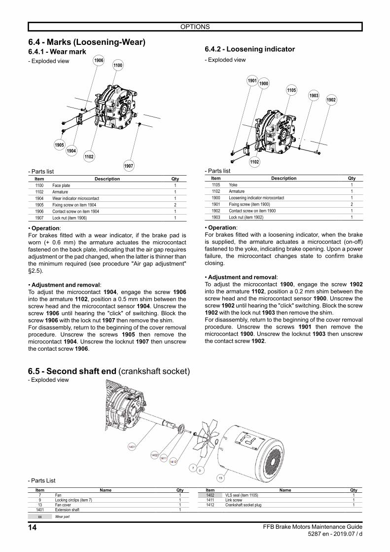
6.4 - Marks (Loosening-Wear)6.4.1 - Wear mark- Exploded view 1906
1100
1907
11021904
1905
- Parts listItem Description Qty1100 Face plate 11102 Armature 11904 Wear indicator microcontact 11905 Fixing screw on item 1904 21906 Contact screw on item 1904 11907 Lock nut (item 1906) 1
• Operation:For brakes fitted with a wear indicator, if the brake pad is worn (+ 0.6 mm) the armature actuates the microcontact fastened on the back plate, indicating that the air gap requires adjustment or the pad changed, when the latter is thinner than the minimum required (see procedure "Air gap adjustment" §2.5).
• Adjustment and removal:To adjust the microcontact 1904, engage the screw 1906 into the armature 1102, position a 0.5 mm shim between the screw head and the microcontact sensor 1904. Unscrew the screw 1906 until hearing the "click" of switching. Block the screw 1906 with the lock nut 1907 then remove the shim.For disassembly, return to the beginning of the cover removal procedure. Unscrew the screws 1905 then remove the microcontact 1904. Unscrew the locknut 1907 then unscrew the contact screw 1906.
6.4.2 - Loosening indicator- Exploded view
1901 19001105
19031902
1102
- Parts listItem Description Qty1105 Yoke 11102 Armature 11900 Loosening indicator microcontact 11901 Fixing screw (item 1900) 21902 Contact screw on item 1900 11903 Lock nut (item 1902) 1
• Operation:For brakes fitted with a loosening indicator, when the brake is supplied, the armature actuates a microcontact (on-off) fastened to the yoke, indicating brake opening. Upon a power failure, the microcontact changes state to confirm brake closing.
• Adjustment and removal:To adjust the microcontact 1900, engage the screw 1902 into the armature 1102, position a 0.2 mm shim between the screw head and the microcontact sensor 1900. Unscrew the screw 1902 until hearing the "click" switching. Block the screw 1902 with the lock nut 1903 then remove the shim.For disassembly, return to the beginning of the cover removal procedure. Unscrew the screws 1901 then remove the microcontact 1900. Unscrew the locknut 1903 then unscrew the contact screw 1902.
6.5 - Second shaft end (crankshaft socket)- Exploded view
- Parts ListItem Name Qty Item Name Qty
7 Fan 1 1402 VLS seal (item 1105) 19 Locking circlips (item 7) 1 1411 Link screw 1
13 Fan cover 1 1412 Crankshaft socket plug 11401 Extension shaft 1
xx Wear part

15
en
OPTIONS
FFB Brake Motors Maintenance Guide5287 en - 2019.07 / d
6.6 - Speed and position feedback devices - Exploded view FFB brake + incremental or absolute encoder (Aluminium: size 71 to 180 or cast iron: size 80 to 160)
18021803
159/2
14001800
1401
159/1299
14031404
79
27
13
- Parts listItem Description Qty Item Description Qty
7 Fan 1 1400 Extension/shaft link screw 19 Locking circlips (item 7) 1 1401 Extension 1
13 Ventilation cover 1 1403 Fan adapter socket 127 Cover fixing screw (item 13) 3 or 4 1404 Socket fixing screw 1
159/1 Encoder 1 1800/1801 Spacer (and extension) 1 to 3159/1 Connector 1802 Fixing bracket 2299 Fixing screw 2 1803 Fixing screws 1
• Disassembly, Replacement:- Disconnect the connector 159/2 fastened to the terminal
box body.- Unscrew the screws 27 from the cover, remove the metal cover 13.- Unscrew the screw 1404 and remove the fan with its socket 1403 and the circlips 9.- Unscrew the screw 299, unscrew the encoder hooping ring (radial screw) from the extension 1401; remove the encoder.
• Reassembly:- Replace the spacer 1800 tightened to the torque of 5.75 Nm. Check the beating ≤ 0,05 mm. Replace the spacer extension 1801 and tighten to the torque of 5.75 Nm ±10% for FFB1 up to 5.- Fit the (new) encoder on the shaft extension 1401.- Block the encoder by screwing to the torque of 0.8 Nm ±10% the screw 299 on the spacer extension 1800.- Tighten the encoder fixing screw to the torque, according to supplier instruction (Heidenhain: 1.1 Nm ±0,1 N.m; Hengstler: 0.6 Nm ±5%; Ideacod: 1.5 Nm ±10%).- Fit the fan adapter socket 1403, screw 1404 to the torque of 3 Nm ±10%. Insert the fan 7 on the socket 1403 then block on the axis with fan lock washer 9.
After intervention, always close the cover(s) of terminal boxes and the caps.

16
OPTIONS
FFB Brake Motors Maintenance Guide5287 en - 2019.07 / d
6.7 - Forced ventilation kit- Exploded view
0007
0027
1405
0013
- Parts listItem Description Qty
7 Forced ventilation 113 Forced ventilation cover 127 Cover fixing screw (item 13) 3 or 4
1405 Yoke borehole plug 1
• Disassembly, Replacement:- Unscrew the screws 27 from the cover, remove the cover 13 fitted with forced ventilation.When replacing the standard auto-ventilation with forced ventilation, remove the fan 7 by removing the axial holding circlips 9 (see §2.1), remove the extension 1401 and stop with plug 1405.• Reassembly:- Reverse the removal procedure.
6.8 - IP65 10 pin 16A connector kitThe LSES 71 to 132 4-pole motors can be fitted with a connector compliant with UL and CSA standards as per the following two versions:- WMS or male version, closed with lead cover
- WMFS or full version, with female extension cover on the side, docking brass PE ISO 25 for cable entry (not supplied) between 12.5 and 18 mm.
See connection diagram § 8.
6.9 - Particular conditions of use - Thermal protections (§8)
- Heating resistors (§8)
- Surface temperatures:As standard, the maximum temperature of our brake motors is +125°C with a maximum ambient temperature ≤ +40°C. Without derating the brake motor, the maximum surface temperature shall be:• +135°C if 40°C ≤ 50°C• +145°C if 50°C ≤ 60°C
Caution: The motor's surface temperature during operation requires wearing PPEs when handling parts and during maintenance operations.
- Maintenance of main bearings:When detecting the following on the brake motor:• abnormal noise or vibrations,• abnormal heating on the bearing, check their condition.Change damaged bearings as soon as possible to prevent additional damage to the brake motor and driven devices.When one bearing requires to be changed, also change the other bearing. The floating bearing shall ensure expansion of the rotor shaft (check its identification upon disassembly).Always change the sealing gaskets when changing the bearings.
- SealingAfter removing the bleeding plugs, refit them to ensure the brake motor achieves the IP55 protection rating.
Non-ventilated brake (IC410): using the brake exclusively as a parking brake. Service braking is forbidden.Dust must be removed regularly to prevent it from building up.
For motors with voltages other than the catalogue standard, with low voltage starting or running under variable voltage or frequency: separate brake supply is required. (Also in the case of a 20V DC coil).

17
en
OPTIONS
FFB Brake Motors Maintenance Guide5287 en - 2019.07 / d
6.10 - Use in Atex zone 22 Specific ATEX 11 marking (§1.1):
FFB370NU001
Mf : 52 Nm
S N° : 9999999/001 U : 180 VDC I : 345 mA
Motor size : 168Nmax : 3600 rpm
II 3 D Ex tc IIIB T125°C Dc
FFB 3 6.5 kg
II 3D Ex tc IIIB: Group II, category 3, non-conductive dusts.T125°C: Maximum surface temperature Dc: Equipment protection level Nmax 3600 rpm: maximum rotation speed in Atex.
The brake must be assembled with a motor which respects the same EXAT level requirements at least.
If the brake is not equipped with a release/application indicator, check the clearance periodically according to the rates and the energy to be dissipated on each braking operation (see technical catalogue ref 5329 § Operation).Those persons required to work on electrical installations and equipment in zones where there is a risk of explosion must be specially trained in the necessary skills.
In effect, they must be familiar not only with the electrical risks, but also with those that are due to the chemical properties and physical characteristics of products used in the installation (gas, vapour, dust), as well as the environment in which the equipment operates. These elements dictate the risk of fire and explosion.
In particular, they must be informed and aware of the specific safety reasons and requirements in order to adhere to them.For example:- do not open when powered up, - do not open when powered up in atmospheres
D21containing explosive dust, - do not repair when powered up,- do not manoeuvre when on load,- wait several minutes before opening,- replace the seals tightly to ensure watertightness.

18
REPAIR GUIDE
FFB Brake Motors Maintenance Guide5287 en - 2019.07 / d
7 - REPAIR GUIDE Incident Possible cause RemedyAbnormal noise From motor or driven machine? Disconnect the motor from the driven device and test the motor aloneNoisy brake motor Mechanical cause: if the noise persists after powering
off- Vibrations
Check that the key complies with the type of balancing- Check the condition of the bearings
- Faulty bearing - Change the bearings as soon as possible- Sensor extension (item 1401) fitted improperly - See adjustment § 6.6- Mechanical friction: ventilation, coupling - Check and change the faulty partElectrical cause: if the noise stops after power drops - Check the supply at the motor terminals
- Check the drive setting- Normal voltage and 3 phases balanced - Check the plate connection and strip tightening - Abnormal voltage - Check the supply line- Unbalance of phases - Check the resistance of windingsOther possible causes:- bad drive setting- drive malfunction
Refer to the drive manual
Abnormal motor heating
- Faulty ventilation - Check the environment- Clean the ventilation cover and the cooling fins- Check the fitting of the fan onto the shaft
- Faulty supply voltage - Check- Strip coupling error - Check- Overload - Check the intensity absorbed with respect to that indicated in the motor
information plate- Partial short circuit - Check electrical continuity of the windings and/or the installation- Phase unbalance - Check the resistance of windingsOther possible causes:- bad drive setting
Refer to the drive manual
Motor does not start Empty:- Mechanical blocking
- Release the brake and motor powered off: check by hand that the shaft turns freely
- Power supply line interrupted - Check the fuses, electric protection, starting device- Position return (drive message) - Check the wiring, drive setting, operation of the position sensor- Thermal protection - CheckIn charge:- Unbalance of phases
Powered off:- Check the rotation direction (order of the phases)- Check the resistance and continuity of the windings- Check the electric protection
- Drive - Check the setting, dimensioning (Max current delivered by the speed drive)
- Position return (drive message) - Check the wiring, drive setting, operation of the position sensor- Thermal protection - Check
The brake does not release
- The voltage is present at the coil's terminals The air gap is too big, the yoke does not attract the armature- Adjust and check disc wearThe voltage is too low U < 0.8Un- Restore the voltage to its nominal valueThe coil is off, its resistance is infinite- Change the complete brake unit or the coil
- The lever rod is in abutment on the cover - See adjustment section 6.1 ref.1406- Mobile parts are stuck - Remove, clean, and look for the cause of sticking- No more voltage at the coil terminals The cell is inoperative
- Test it- Drive - Check that the brake supply is separate from the motor's
The call time is too long
- Check the voltage at the coil terminals The voltage is too low U < 0.8Un (Un: according nominal power supply)- Restore the voltage to its nominal value
- The air gap is too wide - Readjust- The braking moment has increased - Return to the initial setting or consult
The drop time is too long
- Check that the power off is performed on the direct - Connect the cell as per the mark (A) power off on the direct
The brake is noisy when released
- Irregular or excessive air gap - Remove if necessary and clean (see §4)- Foreign material in the air gap - Clean- Extension shaft 1401 fitted incorrectly - See encoder reassembly section 6.6- Drive - Check that the brake supply is separate from the motor's
The braking moment is insufficient
- The friction faces are not clean and dry - Clean the friction faces- Redefine the braking moment
- Pollution due to environment - Clean friction faces. If disc is marked, replace it- The disc is worn - Change the disc
The brake is applied (drops) but braking is weak
- Insufficient spring pressure - Check pad wear. Increase the number of springs- Correct spring pressure - Check the surface wear of the armature
- Use a blower to clean dust due to frictionPermanent pad friction
- The air gap is insufficient - Adjust the air gap

19
CONNECTION DIAGRAMS
FFB Brake Motors Maintenance Guide5287 en - 2019.07 / d
8 - CONNECTION DIAGRAMS8.1 - Motor: reminder� Check the rotation direction of the drive shaft.
L1 - L2 - L3 L1 - L3 - L2
1 SPEED - 2 VOLTAGES
L1 - L2 - L3
W2 U2 V2
L1 L2 L3
U1 V1 W1
W2 U2 V2
L1 L2 L3
U1 V1 W1
1 2 3 4
� Check the brake wiring according to the power supply.
8.2 - Brake: diagram under the TB cover8.2.1 - 180VDC brake coil for standard 1-speed brake motor (Max power supply 500V)Wires spotted + flag
BOBINEFREIN
BRAKINGCOIL
654270A
DEB
RA
NC
HER
LE BLO
C R
EDR
ESSEUR
POU
R ESSA
I D'ISO
LEMEN
T OU
DIELEC
TRIQ
UE
DISC
ON
NEC
T THE R
ECTIFIER
CELL W
HEN
TESTING
FOR
CU
RR
ENT IN
SULATIO
N O
R D
IELECTR
IC.
634118 fr-en/f
IMPO
RTA
NT
1 vitesse - 2 tensions (rapport 1.732) 1 bobinage1 speed- 2 voltage (ratio 1.732) 1 w
inding
W2 T6
U1 T1
U2 T4
V1 T2
V2 T5
W1 T3
W2 T6
U1 T1
U2 T4
V1 T2
V2 T5
W1 T3
**S08
**S08
**débrancher les shunts dans le cas d'une alimentation séparée**disconnect the shunts for separate power supply
(A) coupure sur continu : temps de réponse réduitobligatoire en levage : ENLEVER LE STRAP
(A) DC braking : shorter response timeMandatory for lifting application : REMOVE WIRE
Schéma de branchem
ent frein / Brake connection diagram
AlimentationPower supply
BobineCoil
400V AC230V AC
230V AC127V AC
180V DC100V DC
180V DC100V DC
Câblage*Cabling*
2
1
Bobine/coilAlimentationPower supply
S O8~
~
~ _ -+ ++
(A)±15%
2
1
*suivant alimentation et bobine* according power supply and coil*suivant alimentation et bobine* according power supply and coil
�8.2.2 - 180VDC brake coil for 2-speed motor with 2 windings, 1 voltage, built-in supply
IMPORTANTDébrancher le bloc redresseur
pour essai d’isolement ou diélectriqueDisconnect the rectifier cell when testing
for current insulation or dielectric
1U2 2U2 1 U1+ -
2 SO3
Bobine/coil
350V AC à/to 460V AC 180V DC
AlimentationPower supply
BobineCoil
400V AC
230V AC
180V DC
180V DC
Câblage*Cabling*
2
1
*suivant alimentation et bobine* according power supply and coil*suivant alimentation et bobine* according power supply and coil
�8.2.3 - 20VDC brake coil, separate power supply 24V - (F)LS(ES) 71 to 180
IMPORTANTDébrancher le bloc redresseur
pour essai d’isolement ou diélectriqueDisconnect the rectifier cell when testing
for current insulation or dielectric
Schéma de branchementConnection diagram
FREIN - BRAKECoupure sur le continu(obligatoire en levage)ENLEVER LE STRAPConnection for shorter
response time(mandatory for hoisting)REMOVE THE STRAP
24V
20V
E FS O6
~
~
~ -+
�8.2.4 - Connection for reduced response time TRR: built-in power supply mandatory
Freinbrake
2 noir/rouge2 black/red
Alim. / P. supply400V AC
Bobine / Coil180V DC
+ -2 blanc2 white
634
108
/ b
W2 U2 V2
U1 V1 W1
W2 U2 V2
V1 W1U1

20
CONNECTION DIAGRAMS
FFB Brake Motors Maintenance Guide5287 en - 2019.07 / d
8.3 - Options8.3.1 - Standard thermal protections, class F, 150°C
Thermal protections
Double PTO Triple CTP
Cut-off current 1.6A - cosφ 0.6 -RMS voltage 250V 2.5V max
Fixing on clamp terminal + flag (purple/white)
on board (except HA71: on clamp terminal)+ flag (black/black)
8.3.2 - Standard thermal probesThermal probes PT100 PT1000 (ex-KTY)Measurement current 10mA max 10mA maxRMS voltage - -Fixing on clamp terminal
(3 wires black/red/black)on clamp terminal(brown/white)
8.3.3 - IndicatorsIndicators Release indicator
(Open/Close)Wear indicator
Current 6A 6AVoltage 250V 250V
Fixingon clamp terminal(3 wires blue/black/grey)Black/Blue = NO Black/Grey = NC
on clamp terminal(3 wires blue/black/grey)Black/Blue = NO Black/Grey = NC
NO: normally open; NC: normally closed
Wires spotted + flag
DÉTECTEURDE
DESSERRAGE
RELEASEINDICATOR
654272A
DÉTECTEURD’USURE
WEARINDICATOR
654271A
8.3.4 - DMDDMD Power supply Position indicator
(Closed)Current 6A 1AVoltage 20V 20V
Fixing on terminals (2 wires black)Markers 1 and 2
on terminals (2 wires black)Markers 3 and 4
Option DMD wiring diagram (634269)
DEBRANCHER LES ALIMENTATIONSPOUR ESSAI D'ISOLEMENT OU DIELECTRIQUE
DISCONNECT THE SUPPLIES WHENTESTING FOR CURRENT INSULATION OR DIELECTRIC.
6342
69 fr
-en/
a
IMPORTANT
1 vitesse - 1 tension - 1 bobinage1 speed - 1 voltage - 1 winding
W2
T6
U1
T1
U2
T4
V1
T2
V2
T5
W1
T3
W2
T6
U1
T1
U2
T4
V1
T2
V2
T5
W1
T3
**S
08
**S
08 **dé
bran
cher
les
shun
ts d
ans
le c
as
d'un
e al
imen
tatio
n sé
paré
e**
disc
onne
ct th
e sh
unts
fo
r sep
arat
e po
wer
sup
ply
coupure sur continu : temps de réponse réduitDC braking : shorter response time
Bobine freinBrakecoil
7 6 5 4 3 2 1
(A)
±15%
(A)
DMD
RD WH
20V±15%
20V
8.3.5 - Speed and position encoders �Standard incremental encoder: 5VDC 1024 pts/tr or 4096 pts/trSeparate supply brake
Terminal No. Connection Colour1 0V White2 +VCC Brown3 A Green4 B Yellow5 0 Grey6 A Pink7 B Blue8 0 Red9 Mass -
10 Mass -11 Mass -12 Mass -
View of M23 male connector base at the encoder end
Standard absolute encoder: 10/30 VDC, SinCos SSI multi-turn - Brake with separate power supply Terminal No. Connection Function
1 0V Coder mass2 +VCC Supply voltage3 Clock+ Clock signal4 Clock- Clock signal5 Data+ Data signal6 Data- Data signal7 SET Current position defined at 0 (reset)8 DIR Clockwise or anti-clockwise counting
direction9 A Sine output (incremental)
10 A Sine output (incremental)11 B Cosine output (incremental)12 B Cosine output (incremental)
8.3.6 - Forced ventilation �Single phase forced ventilation for LS 71
I N
U1 = blueU2 = brown
U1 U2
230 V singlephase for HA71
C
Single phase forced ventilation for (F)LS(ES) 80 to 132
Motor type
Condensers
CP1 CP2
LS 80 1.5 µf 1.5 µf
LS 90 to 132
U = 230V Supply on U and WU = 400V Supply on V and W
3 µf 2 µf
Brown
Blue
Black
CP2
ZU
CP1
W V
Single phase ventilation 230 or 400 Vfor HA 80 --> 132
View of M23 male connector base at the encoder end
�

21
RECYCLING
FFB Brake Motors Maintenance Guide5287 en - 2019.07 / d
Three phase forced ventilation for (F)LS(ES) 160, 180THREE PHASE FORCED VENTILATION
HA 160
1 SPEED - 2 VOLTAGES
L1 - L2 - L3
W2 U2 V2
L1 L2 L3
U1 V1 W1
W2 U2 V2
L1 L2 L3
U1 V1 W1
8.3.7 - Plug-in connector
Côté Client / Customer side
Côté Moteur / Motor side
Côté Client / Customer sideCôté Moteur / Motor side
Relais de
contrôle
Pilotrelay
L2
L3
L1
2
3
4
5
1 6
7
8
9
10
CTP/PTCPTO/PTF
2
1 6
7
3
4
5
8
9
10
FREIN ALIMENTATION SÉPARÉESEPARATE BRAKE POWER SUPPLY
L2
L3
L1
2
3
4
5
1 6
7
8
9
10CTP/PTCPTO/PTF
2
1 6
7
3
4
5
8
9
10
Coupure sur le continu : côté moteur connecter les 2 fils bleus (bornes 1 et 2) à la place du strap de la cellule SO8DC breaking : connect on motor side the two blue leads (terminals 1 and 2 ) instead of SO6 strap
634128/b
PT 100
PT 100
Relais de
contrôle
Pilotrelay
W2
U2
V2
ouor
U1
V1
W1
ouor
W2
U2
V2
U1
V1
W1
400V AC230V AC
Alimentation freinBrake supply
FREIN ALIMENTATION INCORPORÉEBUILT-IN BRAKE POWER SUPPLY
S O8
~~
_-
+++
S O8
~~
_-
+++
Alimentation / Power supply : 400V ACAlimentation / Power supply : 230V AC
Bobine/coil : 180V DCBobine/coil : 180V DC2
1
Alimentation / Power supply : 400V ACAlimentation / Power supply : 230V AC
Bobine/coil : 180V DCBobine/coil : 180V DC2
12
1
BobineCoil
BobineCoil
2
1
8.3.8 - VARMECA 31 / 32
U
V
W
Supply to 2nd motor(mains voltage output)
: 400/480V mains
Brake
180VDC
1: 230V mains2
U
ESFRPE
PE
VW+- F2
L1 L2 L3
F1
Power supply mains* 230/400V
*NOTE: For single phase versions, the supply is made on the L and N terminals.
To brakecoil
Dual-alternate(208-240VAC)
Supply to 2nd motor (variable voltage and frequency output)
Mono-alternate (380-480VAC mains)
Ribbon cable to options connector
L1
L3
S08
+ ++
1 2
ESFR VMA 31/32
8.3.9 - VARMECA 33 / 34 option
Opto Triac
Fu:
VMA 33/34T180 VDC
VMA 33/34TL100 VDC
Dedicated logic output
AC power supply for a 2nd brake
1.25 A600 V
L1
L3
F1
F2
ESFR VMA 33/34
8.3.10 - ID 300/302 Brake control option
L1 PEL2 L3
+ -++ -
Optionalbrakingresistor(1)
Drive AC Powerconnectors
ID-SIZEx-Brake Contactorconnectors
Brake DC supply(already wired)
(already wired)
OptionalEMC filter
Fuses
Mains supply(3 phases)
Supplyground
Groundconnection
9 - RECYCLINGAt end of life, call upon a material disposal company to dispose of the different brake motor components.

22
CONNECTION DIAGRAMS
FFB Brake Motors Maintenance Guide5287 en - 2019.07 / d
NOTES

23
CONNECTION DIAGRAMS
FFB Brake Motors Maintenance Guide5287 en - 2019.07 / d
NOTES

Moteurs Leroy-Somer SASSiège social : Boulevard Marcellin Leroy - CS 10015
16915 ANGOULÊME Cedex 9Société par Actions Simplifiées au capital de 65 800 512 $
RCS Angoulême 338 567 258www.leroy-somer.com