brakes caliper brakes: hydraulically actuated brakes 04-11 m… · wet conditions seal protection...
TRANSCRIPT
Caliper brakes:
20 APRIL 2011 MOTION SYSTEM DESIGN • motionsystemdesign.com
Caliper disc brakes are among the most tried and true braking technologies
in industrial use. Designed to clamp onto both sides of discs or flat rails, these specialized brakes create friction that ex-
erts a braking force on the disc attached to the rotating shaft, or
on a rail or fin in linear motion appli-cations. Caliper brakes are well suited
for a range of industrial uses, such as construction machinery, material han-
dling equipment, metalworking machin-ery, automated assembly machines, and
o t h e r heavy equipment.Spring-engaged caliper brakes use spring forces to se-
cure the load for dynamic braking and static holding appli-cations. The return mechanism is where designs diverge:
21APRIL 2011 MOTION SYSTEM DESIGN • motionsystemdesign.com
Brakes can be either hydrauli-cally or pneumatically released. Pneumatic systems (using air) are widely used in manufactur-ing to operate at low power and pressures, whereas hydraulic systems (using fluids) are used where greater amounts of pow-er and pressure are required.
The decision to use one brake style over the other is determined by the application’s torque requirement, system cost, working environment, and safety.
Determining required torque
The amount of torque — a
function of the brake’s clamp-ing force and the working ra-dius of a disc in rotary applica-tions — needed to stop or hold the load is the most important factor when choosing a caliper brake.
Typically, spring-engaged, air-released (pneumatic) brakes are used for stopping and hold-ing in moderate torque range applications, while spring-en-gaged, hydraulically-released brakes are used when higher torque is needed.
In linear motion applica-tions, a caliper brake clamp force value is used to determine the time and distance needed
to perform a full stop.Other brake considerations
include the disc diameter, disc heat sink capacity, and friction facing life. (Examples later in this article illustrate the steps necessary to arrive at these values.)
Brake torque (τ) is equal to the pressure on the disc (F) multiplied by the design co-efficient of friction (r). With r = 0.35 and pressure on two facing discs, total brake torque equals F × 2 × 0.35.
Cost comparison While hydraulic systems
accommodate greater torque
Hydraulics versus pneumaticsWhen it comes to choosing the right brakes for an application, which is better — pneumatically or hydraulically released technology? Learn where each type is most appropriate.
Edd BrooksNexen Group Inc. Vadnais Heights, Minn.
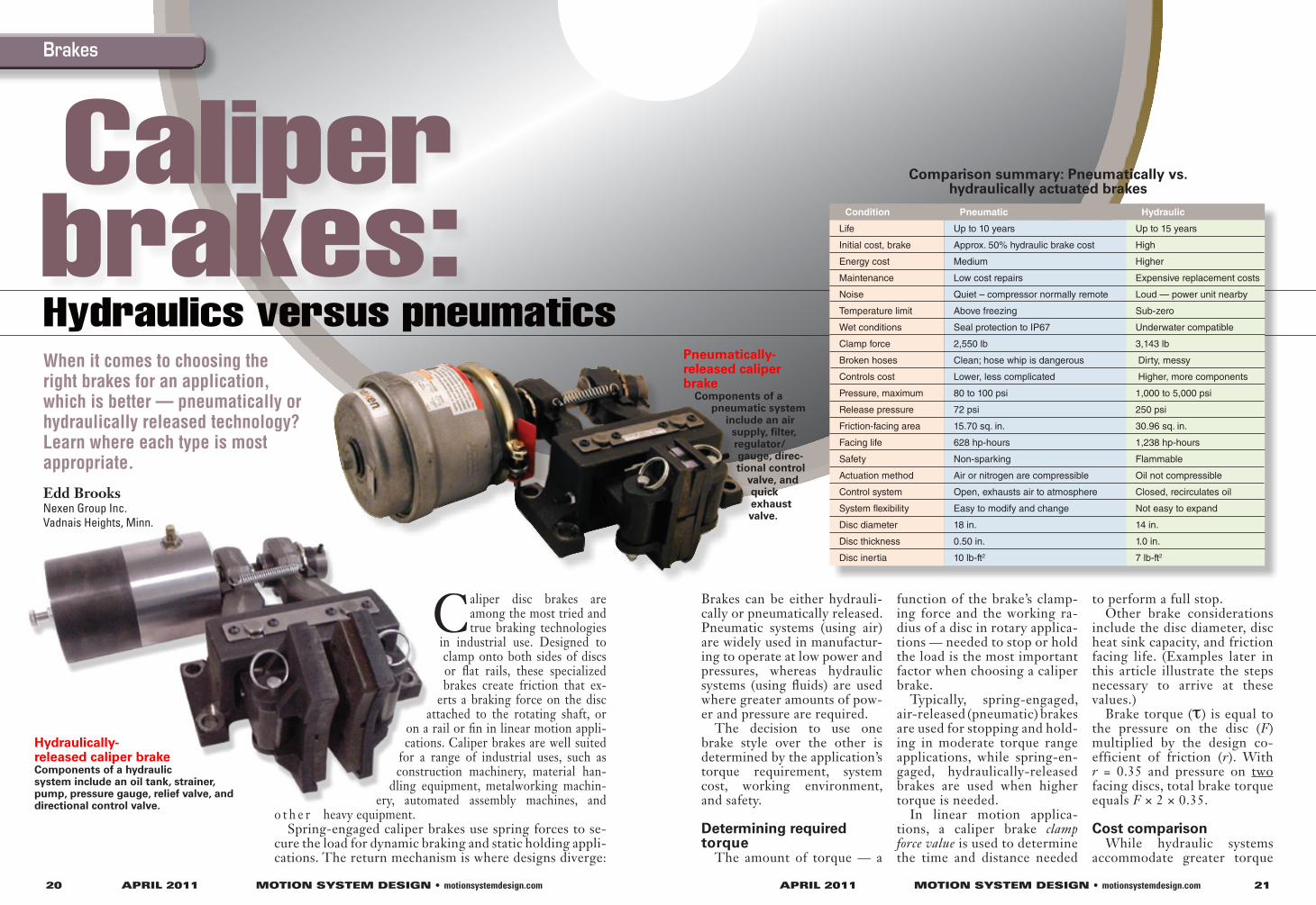
Pneumatically- released caliper brake
Components of a pneumatic system
include an air supply, filter, regulator/gauge, direc-tional control
valve, and quick exhaust valve.
Hydraulically- released caliper brakeComponents of a hydraulic system include an oil tank, strainer, pump, pressure gauge, relief valve, and directional control valve.
Condition Pneumatic Hydraulic
Life Up to 10 years Up to 15 years
Initial cost, brake Approx. 50% hydraulic brake cost High
Energy cost Medium Higher
Maintenance Low cost repairs Expensive replacement costs
Noise Quiet – compressor normally remote Loud — power unit nearby
Temperature limit Above freezing Sub-zero
Wet conditions Seal protection to IP67 Underwater compatible
Clamp force 2,550 lb 3,143 lb
Broken hoses Clean; hose whip is dangerous Dirty, messy
Controls cost Lower, less complicated Higher, more components
Pressure, maximum 80 to 100 psi 1,000 to 5,000 psi
Release pressure 72 psi 250 psi
Friction-facing area 15.70 sq. in. 30.96 sq. in.
Facing life 628 hp-hours 1,238 hp-hours
Safety Non-sparking Flammable
Actuation method Air or nitrogen are compressible Oil not compressible
Control system Open, exhausts air to atmosphere Closed, recirculates oil
System flexibility Easy to modify and change Not easy to expand
Disc diameter 18 in. 14 in.
Disc thickness 0.50 in. 1.0 in.
Disc inertia 10 lb-ft2 7 lb-ft2
Comparison summary: Pneumatically vs. hydraulically actuated brakes
BrakesBrakes
22 APRIL 2011 MOTION SYSTEM DESIGN • motionsystemdesign.com
requirements, pneumatic sys-tems are more cost-effective. Why?
Pneumatic pressure is usual-ly cheaper to obtain — as most industrial facilities already have compressed air readily available.
And, because many systems don’t require extremely high forces and only need to make movements from one position to another (without making intermittent stops), pneumatic systems are often the easier and less costly choice.
Environmental factorsAlong with cost advantages,
pneumatic systems provide envi-ronmental benefits over hydrau-lic systems. When a hydraulic system leaks, it leaks hydraulic fluid that could contaminate the environment or product being manufactured.
When pneumatic systems leak, only air escapes, and the air can be kept very clean with properly selected and main-tained equipment.
This environmental advan-tage can be particularly impor-tant in food, pharmaceutical, printing, and other facilities where cleanliness is critical to the manufacturing process.
Pressure ranges and safety factors
Despite these environmental drawbacks, hydraulic systems are able to develop extremely high pressures that produce much higher forces in actuated components than their pneu-matic counterparts. Hydraulic fluids are not compressible, so hydraulic systems offer ex-ceptionally smooth motion of actuated components because there is no “bounce” due to fluid compressing and expand-ing, as is typical of pneumatic systems.
Spring-engaged, air- released caliper brakes
Along with lower cost and environmental advantages, spring-engaged, air-released caliper brakes can include sev-eral features designed for ease of use and increased accuracy: Rectangular friction facings provide reliable clamping on a rail; quick-release facing shoe pins can facilitate fast brake shoe removal from the actuator arms for simple replacement of the friction pad. Interchange-able actuator locations may be mounted on either side of the brake, delivering increased flexibility, and oil-free bear-
ings at all pivot points reduce maintenance requirements. Adjustment screws are also available for maintaining the facing gap in vertical shaft ap-plications, and a built-in man-ual release mechanism allows safe and easy maintenance.
Typical specifications of spring-engaged, air-released cal-iper brakes are as follows:
• Spring hold-off chamber area = 23.758 sq. in.
• Air pressure needed to fully compress the spring = 70 psi
• Spring force = Area × spring force = 23.758 (70) = 1,663 lb
• Caliper mechanical advan-tage = 2.04
• Design coefficient of friction = 0.35
Spring-engaged, hydraulically released caliper brakes
As mentioned, spring-en-gaged, hydraulically released caliper brakes are typically se-lected for applications with greater torque requirements or applications that require brak-ing between actuator move-ments. While a variety of op-tions are available, a brake should be selected with features to simplify setup and enhance performance.
For example, a large fric-tion-facing area lowers fac-ing pressure to provide long friction-facing life. A nested spring design minimizes spring force loss and allows the brak-ing torque to be modified based on specific application require-ments.
Large orifice ports provide for fast actuation and reliable operation — even in tempera-tures as low as -30° F. This provides a significant environ-mental advantage compared to traditional pneumatically-actu-
23APRIL 2011 MOTION SYSTEM DESIGN • motionsystemdesign.com
ated brakes and clutches, which require a minimum operating range of 32° F. Additionally, spring-engaged, hydraulically released caliper brakes can of-fer some of the same features as air-released brakes, including quick-release shoe pins, adjust-ment screws, oil-free bearings at pivot points, interchange-able actuator locations, and a manual release accessory.
Typical specifications of spring-engaged, hydraulically released caliper brakes are as fol-lows:
• Spring hold-off chamber area = 9.62 sq. in.
• Air pressure needed to fully compress the spring = 250 psi
• Spring force = Area x spring force = 2,405 lb
• Caliper mechanical advan-tage = 2.04
• Design coefficient of friction = 0.35
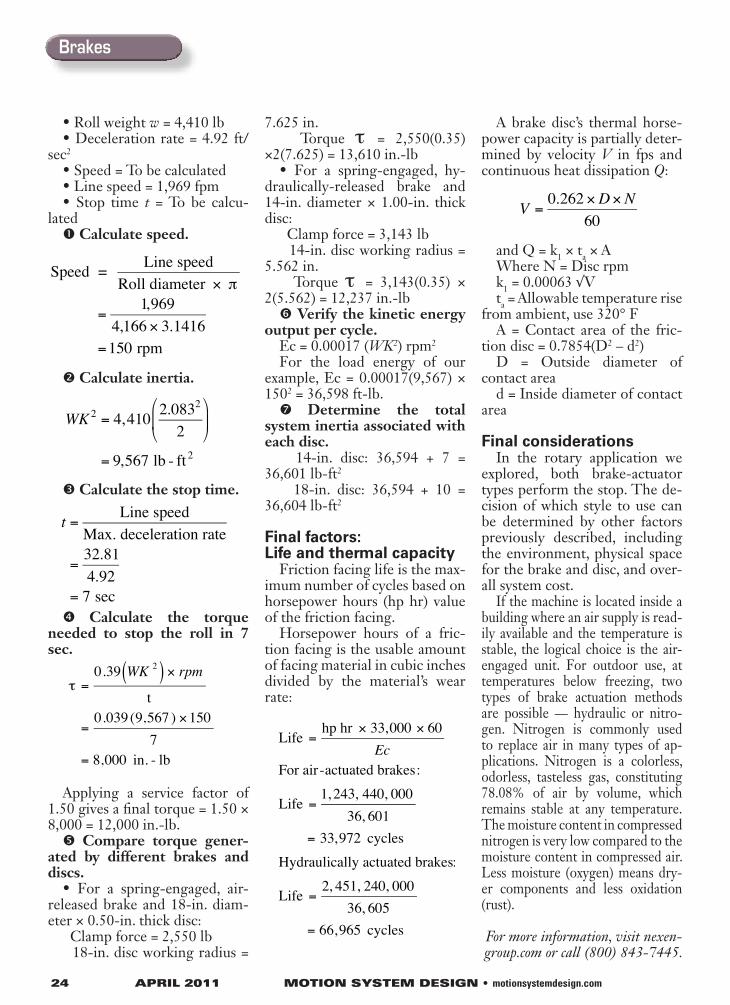
Application example: Air and hydraulically actuated brakes
Calculate the torque needed to stop a mill roll in 7 sec for the following conditions:
• Roll radius d = 2.083 ft
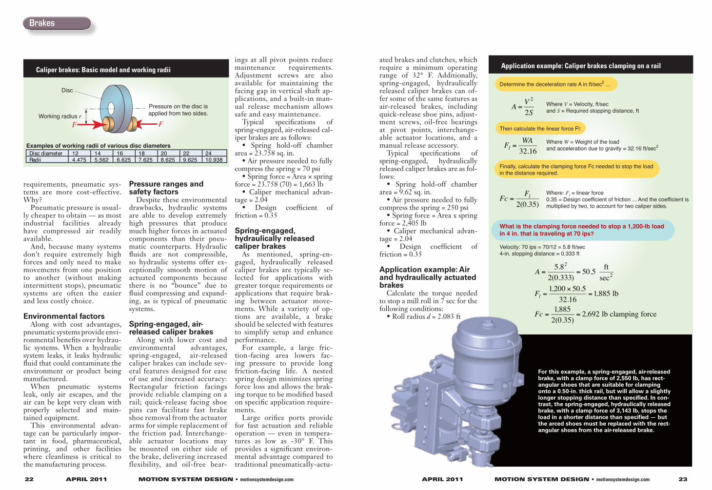
Caliper brakes: Basic model and working radii
Working radius rF F
Disc
Pressure on the disc isapplied from two sides.
Disc diameter 12 14 16 18 20 22 24 Radii 4.475 5.562 6.625 7.625 8.625 9.625 10.938
Examples of working radii of various disc diameters
Determine the deceleration rate A in ft/sec2 ...
Where V = Velocity, ft/sec and S = Required stopping distance, ft
Then calculate the linear force Fl:
Where W = Weight of the load and acceleration due to gravity = 32.16 ft/sec2
Finally, calculate the clamping force Fc needed to stop the loadin the distance required. Where: Fl = linear force 0.35 = Design coefficient of friction ... And the coefficient is multiplied by two, to account for two caliper sides.
What is the clamping force needed to stop a 1,200-lb loadin 4 in. that is traveling at 70 ips?
Velocity: 70 ips = 70/12 = 5.8 ft/sec4-in. stopping distance = 0.333 ft
A =V 2
2S
Fl =WA
32.16
Fc =Fl
2(0.35)
A =5.82
2(0.333)= 50.5 ft
sec2
Fl =1,200 × 50.5
32.16=1,885 lb
Fc =1,885
2(0.35)= 2,692 lb clamping force
Application example: Caliper brakes clamping on a rail
For this example, a spring-engaged, air-released brake, with a clamp force of 2,550 lb, has rect-angular shoes that are suitable for clamping onto a 0.50-in. thick rail, but will allow a slightly longer stopping distance than specified. In con-trast, the spring-engaged, hydraulically released brake, with a clamp force of 3,143 lb, stops the load in a shorter distance than specified — but the arced shoes must be replaced with the rect-angular shoes from the air-released brake.
Brakes
24 APRIL 2011 MOTION SYSTEM DESIGN • motionsystemdesign.com
• Roll weight w = 4,410 lb• Deceleration rate = 4.92 ft/
sec2
• Speed = To be calculated• Line speed = 1,969 fpm• Stop time t = To be calcu-
lated Calculate speed.
Calculate inertia.
Calculate the stop time.
Calculate the torque needed to stop the roll in 7 sec.
τ =0.39 WK 2( ) × rpm
t
=0.039 (9,567 ) ×150
7= 8,000 in. - lb
Applying a service factor of 1.50 gives a final torque = 1.50 × 8,000 = 12,000 in.-lb. Compare torque gener-
ated by different brakes and discs.
• For a spring-engaged, air-released brake and 18-in. diam-eter × 0.50-in. thick disc:
Clamp force = 2,550 lb 18-in. disc working radius =
7.625 in. Torque τ = 2,550(0.35)
×2(7.625) = 13,610 in.-lb• For a spring-engaged, hy-
draulically-released brake and 14-in. diameter × 1.00-in. thick disc:
Clamp force = 3,143 lb 14-in. disc working radius =
5.562 in. Torque τ = 3,143(0.35) ×
2(5.562) = 12,237 in.-lb Verify the kinetic energy
output per cycle.Ec = 0.00017 (WK2) rpm2
For the load energy of our example, Ec = 0.00017(9,567) × 1502 = 36,598 ft-lb. Determine the total
system inertia associated with each disc.
14-in. disc: 36,594 + 7 = 36,601 lb-ft2
18-in. disc: 36,594 + 10 = 36,604 lb-ft2
Final factors: Life and thermal capacity
Friction facing life is the max-imum number of cycles based on horsepower hours (hp hr) value of the friction facing.
Horsepower hours of a fric-tion facing is the usable amount of facing material in cubic inches divided by the material’s wear rate:
A brake disc’s thermal horse-power capacity is partially deter-mined by velocity V in fps and continuous heat dissipation Q:
and Q = k1 × ta × AWhere N = Disc rpmk1 = 0.00063 √Vta = Allowable temperature rise
from ambient, use 320° FA = Contact area of the fric-
tion disc = 0.7854(D2 – d2)D = Outside diameter of
contact aread = Inside diameter of contact
area
Final considerationsIn the rotary application we
explored, both brake-actuator types perform the stop. The de-cision of which style to use can be determined by other factors previously described, including the environment, physical space for the brake and disc, and over-all system cost.
If the machine is located inside a building where an air supply is read-ily available and the temperature is stable, the logical choice is the air-engaged unit. For outdoor use, at temperatures below freezing, two types of brake actuation methods are possible — hydraulic or nitro-gen. Nitrogen is commonly used to replace air in many types of ap-plications. Nitrogen is a colorless, odorless, tasteless gas, constituting 78.08% of air by volume, which remains stable at any temperature. The moisture content in compressed nitrogen is very low compared to the moisture content in compressed air. Less moisture (oxygen) means dry-er components and less oxidation (rust).
For more information, visit nexen-group.com or call (800) 843-7445.
Brakes