bravo platform quick guide - agilent · • “using bravo diagnostics to control the device” on...
TRANSCRIPT
Original Instructions
This guide contains the following topics:• “About this guide” on page 2• “Safety guidelines” on page 3• “Hardware components and axes of motion” on page 4• “Starting up and shutting down” on page 8• “Running a protocol” on page 9• “Stopping or pausing a run” on page 11• “Using Bravo Diagnostics to control the device” on page 13• “Changing the Bravo head” on page 17
Bravo PlatformQuick Guide
About this guide
2 Bravo Platform Quick Guide
About this guide
This guide summarizes the operator instructions in the Bravo Platform User Guide.This guide assumes the following:• The Bravo Platform is installed correctly. For details, see the Bravo Platform Safety
and Installation Guide.• The device profile for the specific Bravo configuration is already created and the
teachpoints are already set. For setup instructions, see the Bravo Platform User Guide.
• You are familiar with the VWorks Automation Control software. See the VWorks Automation Control Quick Start. For detailed instructions, see the VWorks Automation Control User Guide.
Where to find the user documentation
To access the user guides for Agilent Automation Solutions products, do one of the following:• From within VWorks software, select Help > Knowledge Base or press F1.• From the Windows desktop, select Start > Agilent Technologies >
VWorks Knowledge Base.• Go to the online VWorks Knowledge Base at www.agilent.com/chem/askb.
Contacting Agilent Technologies
Web: https://www.agilent.comContact page: https://www.agilent.com/en/contact-us/pageDocumentation feedback: [email protected]
3
Safety guidelines
Bravo Platform Quick Guide
Safety guidelines
WARNINGUsing controls, making adjustments, or performing procedures other than those specified in the user documentation can expose you to moving-parts hazards and hazardous voltage. Before using the Bravo Platform, make sure you are aware of the potential hazards and understand how to avoid being exposed to them.
Ensure that you are trained in the safe operation of the device and that you have read the Agilent Automation Solutions Products General Safety Guide and the safety section of the Bravo Platform Safety and Installation Guide.
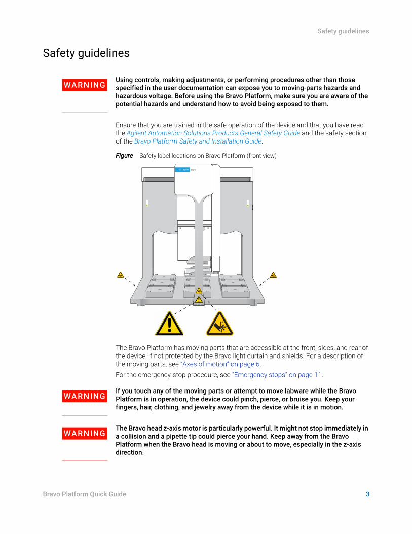
Figure Safety label locations on Bravo Platform (front view)
The Bravo Platform has moving parts that are accessible at the front, sides, and rear of the device, if not protected by the Bravo light curtain and shields. For a description of the moving parts, see “Axes of motion” on page 6.For the emergency-stop procedure, see “Emergency stops” on page 11.
WARNINGIf you touch any of the moving parts or attempt to move labware while the Bravo Platform is in operation, the device could pinch, pierce, or bruise you. Keep your fingers, hair, clothing, and jewelry away from the device while it is in motion.
WARNINGThe Bravo head z-axis motor is particularly powerful. It might not stop immediately in a collision and a pipette tip could pierce your hand. Keep away from the Bravo Platform when the Bravo head is moving or about to move, especially in the z-axis direction.
Bravo
Hardware components and axes of motion
4 Bravo Platform Quick Guide
Hardware components and axes of motion
Primary hardware components
The following figure and table describe the primary hardware components.
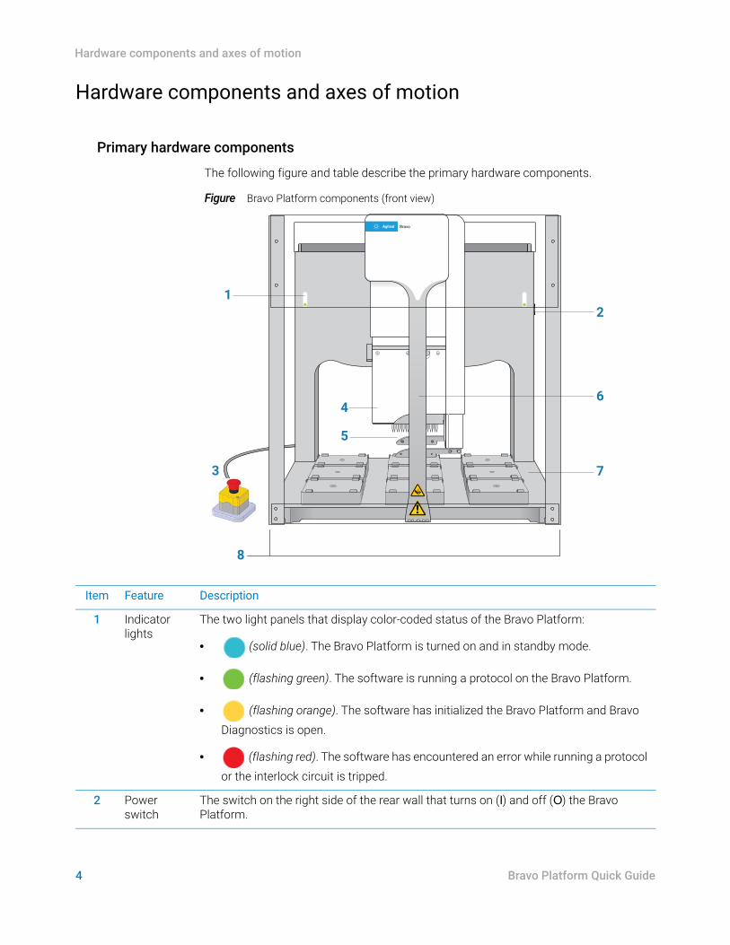
Figure Bravo Platform components (front view)
Bravo
2
6
73
1
4
5
8
Item Feature Description
1 Indicator lights
The two light panels that display color-coded status of the Bravo Platform:
• (solid blue). The Bravo Platform is turned on and in standby mode.
• (flashing green). The software is running a protocol on the Bravo Platform.
• (flashing orange). The software has initialized the Bravo Platform and Bravo Diagnostics is open.
• (flashing red). The software has encountered an error while running a protocol or the interlock circuit is tripped.
2 Power switch
The switch on the right side of the rear wall that turns on (I) and off (O) the Bravo Platform.
5
Hardware components and axes of motion
Bravo Platform Quick Guide
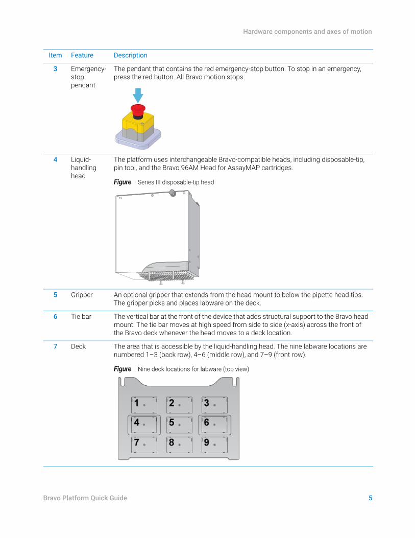
3 Emergency-stop pendant
The pendant that contains the red emergency-stop button. To stop in an emergency, press the red button. All Bravo motion stops.
4 Liquid-handling head
The platform uses interchangeable Bravo-compatible heads, including disposable-tip, pin tool, and the Bravo 96AM Head for AssayMAP cartridges.
Figure Series III disposable-tip head
5 Gripper An optional gripper that extends from the head mount to below the pipette head tips. The gripper picks and places labware on the deck.
6 Tie bar The vertical bar at the front of the device that adds structural support to the Bravo head mount. The tie bar moves at high speed from side to side (x-axis) across the front of the Bravo deck whenever the head moves to a deck location.
7 Deck The area that is accessible by the liquid-handling head. The nine labware locations are numbered 1–3 (back row), 4–6 (middle row), and 7–9 (front row).
Figure Nine deck locations for labware (top view)
Item Feature Description
Hardware components and axes of motion
6 Bravo Platform Quick Guide
Axes of motion
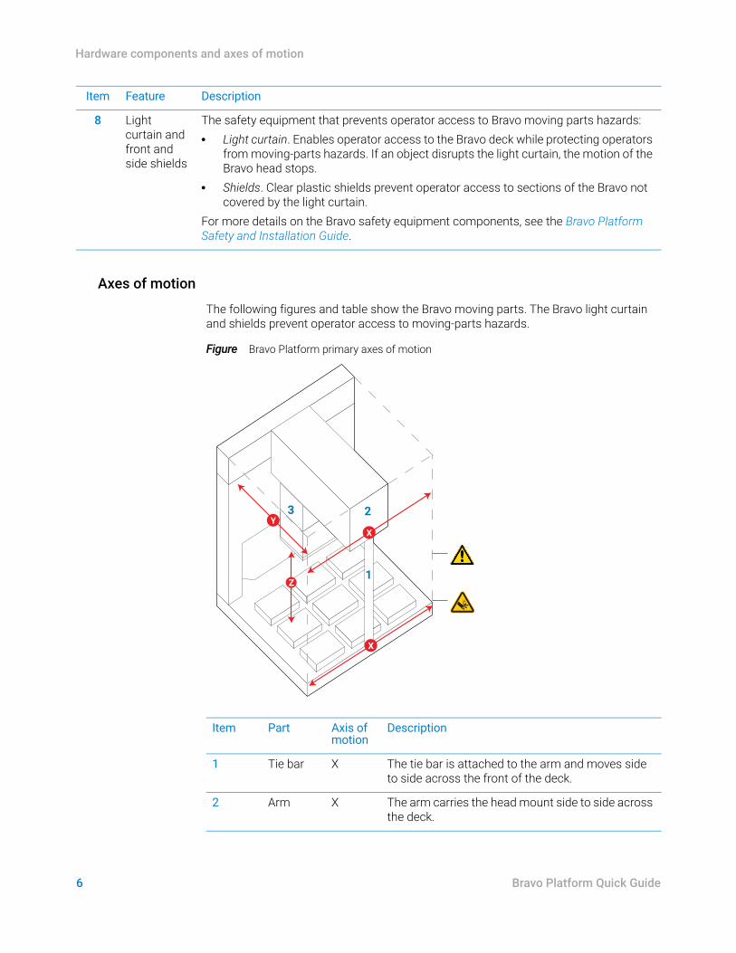
The following figures and table show the Bravo moving parts. The Bravo light curtain and shields prevent operator access to moving-parts hazards.
Figure Bravo Platform primary axes of motion
8 Light curtain and front and side shields
The safety equipment that prevents operator access to Bravo moving parts hazards:• Light curtain. Enables operator access to the Bravo deck while protecting operators
from moving-parts hazards. If an object disrupts the light curtain, the motion of the Bravo head stops.
• Shields. Clear plastic shields prevent operator access to sections of the Bravo not covered by the light curtain.
For more details on the Bravo safety equipment components, see the Bravo Platform Safety and Installation Guide.
Item Feature Description
Item Part Axis of motion
Description
1 Tie bar X The tie bar is attached to the arm and moves side to side across the front of the deck.
2 Arm X The arm carries the head mount side to side across the deck.
00232BravoPinch Hazard
0023
2
XY
X
Z1
23
7
Hardware components and axes of motion
Bravo Platform Quick Guide
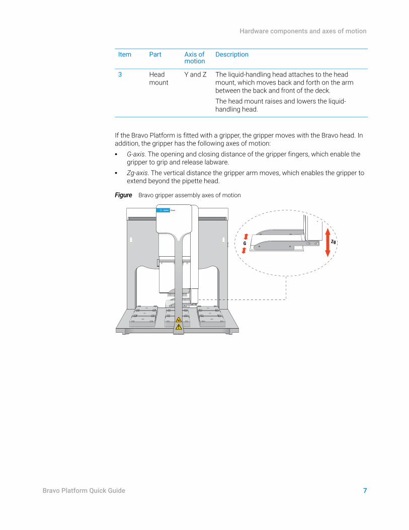
If the Bravo Platform is fitted with a gripper, the gripper moves with the Bravo head. In addition, the gripper has the following axes of motion:• G-axis. The opening and closing distance of the gripper fingers, which enable the
gripper to grip and release labware.• Zg-axis. The vertical distance the gripper arm moves, which enables the gripper to
extend beyond the pipette head.
Figure Bravo gripper assembly axes of motion
3 Head mount
Y and Z The liquid-handling head attaches to the head mount, which moves back and forth on the arm between the back and front of the deck. The head mount raises and lowers the liquid-handling head.
Item Part Axis of motion
Description
Bravo
ZgG
Starting up and shutting down
8 Bravo Platform Quick Guide
Starting up and shutting down
The following procedures describe how to start up and shut down the Bravo Platform when you are operating it as a standalone device. For instructions on how to turn on and turn off the Bravo Platform when it is integrated into a workstation or system, see the workstation or system user documentation.
Starting up the Bravo Platform
To start up the Bravo Platform:1 Turn on any accessories, such as a Pump Module, and ensure that any tubing is
connected. For a description of the Pump Module and autofilling reservoirs, see the Pump Module User Guide.
2 Turn on the computer and the monitor. The Microsoft Windows operating system starts automatically.
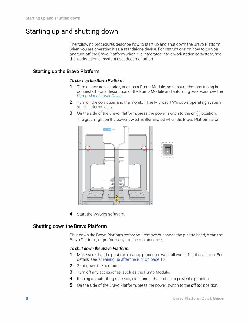
3 On the side of the Bravo Platform, press the power switch to the on (I) position.The green light on the power switch is illuminated when the Bravo Platform is on.
4 Start the VWorks software.
Shutting down the Bravo Platform
Shut down the Bravo Platform before you remove or change the pipette head, clean the Bravo Platform, or perform any routine maintenance.
To shut down the Bravo Platform:1 Make sure that the post-run cleanup procedure was followed after the last run. For
details, see “Cleaning up after the run” on page 10.2 Shut down the computer.3 Turn off any accessories, such as the Pump Module. 4 If using an autofilling reservoir, disconnect the bottles to prevent siphoning.5 On the side of the Bravo Platform, press the power switch to the off (o) position.
BravoBravo
9
Running a protocol
Bravo Platform Quick Guide
Running a protocol
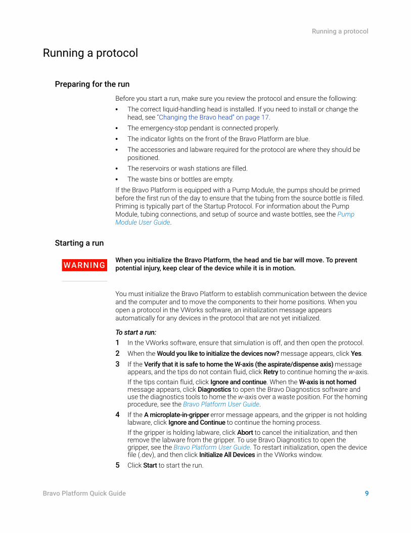
Preparing for the run
Before you start a run, make sure you review the protocol and ensure the following:• The correct liquid-handling head is installed. If you need to install or change the
head, see “Changing the Bravo head” on page 17.• The emergency-stop pendant is connected properly.• The indicator lights on the front of the Bravo Platform are blue.• The accessories and labware required for the protocol are where they should be
positioned.• The reservoirs or wash stations are filled.• The waste bins or bottles are empty.If the Bravo Platform is equipped with a Pump Module, the pumps should be primed before the first run of the day to ensure that the tubing from the source bottle is filled. Priming is typically part of the Startup Protocol. For information about the Pump Module, tubing connections, and setup of source and waste bottles, see the Pump Module User Guide.
Starting a run
WARNINGWhen you initialize the Bravo Platform, the head and tie bar will move. To prevent potential injury, keep clear of the device while it is in motion.
You must initialize the Bravo Platform to establish communication between the device and the computer and to move the components to their home positions. When you open a protocol in the VWorks software, an initialization message appears automatically for any devices in the protocol that are not yet initialized.
To start a run:1 In the VWorks software, ensure that simulation is off, and then open the protocol. 2 When the Would you like to initialize the devices now? message appears, click Yes. 3 If the Verify that it is safe to home the W-axis (the aspirate/dispense axis) message
appears, and the tips do not contain fluid, click Retry to continue homing the w-axis.If the tips contain fluid, click Ignore and continue. When the W-axis is not homed message appears, click Diagnostics to open the Bravo Diagnostics software and use the diagnostics tools to home the w-axis over a waste position. For the homing procedure, see the Bravo Platform User Guide.
4 If the A microplate-in-gripper error message appears, and the gripper is not holding labware, click Ignore and Continue to continue the homing process. If the gripper is holding labware, click Abort to cancel the initialization, and then remove the labware from the gripper. To use Bravo Diagnostics to open the gripper, see the Bravo Platform User Guide. To restart initialization, open the device file (.dev), and then click Initialize All Devices in the VWorks window.
5 Click Start to start the run.
Running a protocol
10 Bravo Platform Quick Guide
Cleaning up after the run
CAUTIONUse only the recommended cleaning materials. Using other cleaning solutions and materials can cause damage to the device. Do not use abrasive, corrosive cleaning agents. Do not use metal brushes.
Use standard laboratory wipes and a mild detergent or ethanol alcohol to clean the exterior painted white surfaces and the metal surfaces of dust, grime, chemical deposits, and other debris.
To clean up the Bravo Platform after a run:1 Check the run log file for errors. For details on the VWorks run log, see the VWorks
Automation Control User Guide.2 Ensure that the tips are ready for the next run:
• Disposable-tip pipette head. You can use the Tips Off task in Bravo Diagnostics to remove any tips that remain on the barrels of the pipette head. For details, see “Using Bravo Diagnostics to control the device” on page 13.
• Fixed-tip pipette head. You can use the Wash Tips task in Bravo Diagnostics to wash the pipette tips.
3 Ensure all pipette head movement has stopped, and then remove any manually placed or unused labware, and clean up any spills or debris.
4 Wash the liquid reservoirs and wash stations.5 If equipped with a Pump Module:
a Optional. Wash the tubing and reinstall the reservoirs or wash stations. Ensure that the tubing is connected to the correct pumps.
b Fill the fluid reservoir bottle, replace the cap, and attach the fluid line that pumps towards the Bravo Platform to the cap connector.
c Empty the waste container, replace the cap, and attach the fluid line that pumps away from the Bravo Platform to the cap connector.
For connection details, see the Pump Module User Guide.6 If equipped with a Weigh Station, recalibrate it if you are changing the tubing
connected to the reservoir, changing the liquid type used in the reservoir, or if more than two weeks have elapsed since the last Weigh Station calibration. For details, see the Bravo Platform User Guide.
11
Stopping or pausing a run
Bravo Platform Quick Guide
Stopping or pausing a run
Emergency stops
An emergency stop might be necessary to prevent a collision of the Bravo head with another object, such as misaligned labware. If you want to temporarily pause and then continue a run, see “Pausing and continuing a run” on page 12.
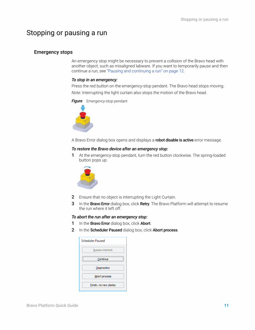
To stop in an emergency:Press the red button on the emergency-stop pendant. The Bravo head stops moving.Note: Interrupting the light curtain also stops the motion of the Bravo head.
Figure Emergency-stop pendant
A Bravo Error dialog box opens and displays a robot disable is active error message.
To restore the Bravo device after an emergency stop:1 At the emergency-stop pendant, turn the red button clockwise. The spring-loaded
button pops up.
2 Ensure that no object is interrupting the Light Curtain.3 In the Bravo Error dialog box, click Retry. The Bravo Platform will attempt to resume
the run where it left off.
To abort the run after an emergency stop:1 In the Bravo Error dialog box, click Abort. 2 In the Scheduler Paused dialog box, click Abort process.
Stopping or pausing a run
12 Bravo Platform Quick Guide
Pausing and continuing a run
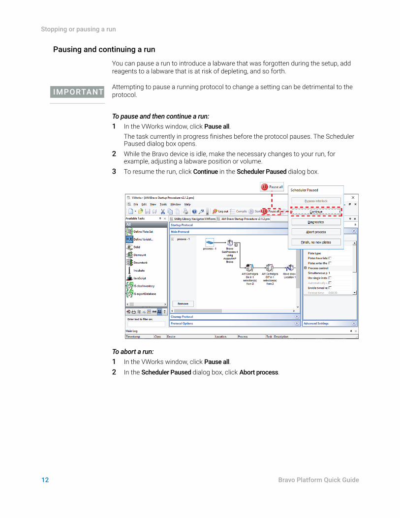
You can pause a run to introduce a labware that was forgotten during the setup, add reagents to a labware that is at risk of depleting, and so forth.
IMPORTANTAttempting to pause a running protocol to change a setting can be detrimental to the protocol.
To pause and then continue a run:1 In the VWorks window, click Pause all.
The task currently in progress finishes before the protocol pauses. The Scheduler Paused dialog box opens.
2 While the Bravo device is idle, make the necessary changes to your run, for example, adjusting a labware position or volume.
3 To resume the run, click Continue in the Scheduler Paused dialog box.
To abort a run:1 In the VWorks window, click Pause all.2 In the Scheduler Paused dialog box, click Abort process.
13
Using Bravo Diagnostics to control the device
Bravo Platform Quick Guide
Using Bravo Diagnostics to control the device
To control the Bravo Platform when you are not running a protocol, you use Bravo Diagnostics. For example, you can use Bravo Diagnostics to run a single task, such as to eject tips, to open and close the gripper, and to change the pipette head.
IMPORTANTSome of the Bravo Diagnostics features are available only if you have VWorks administrator- or technician-level privileges. For details, see your lab administrator.
Opening Bravo Diagnostics
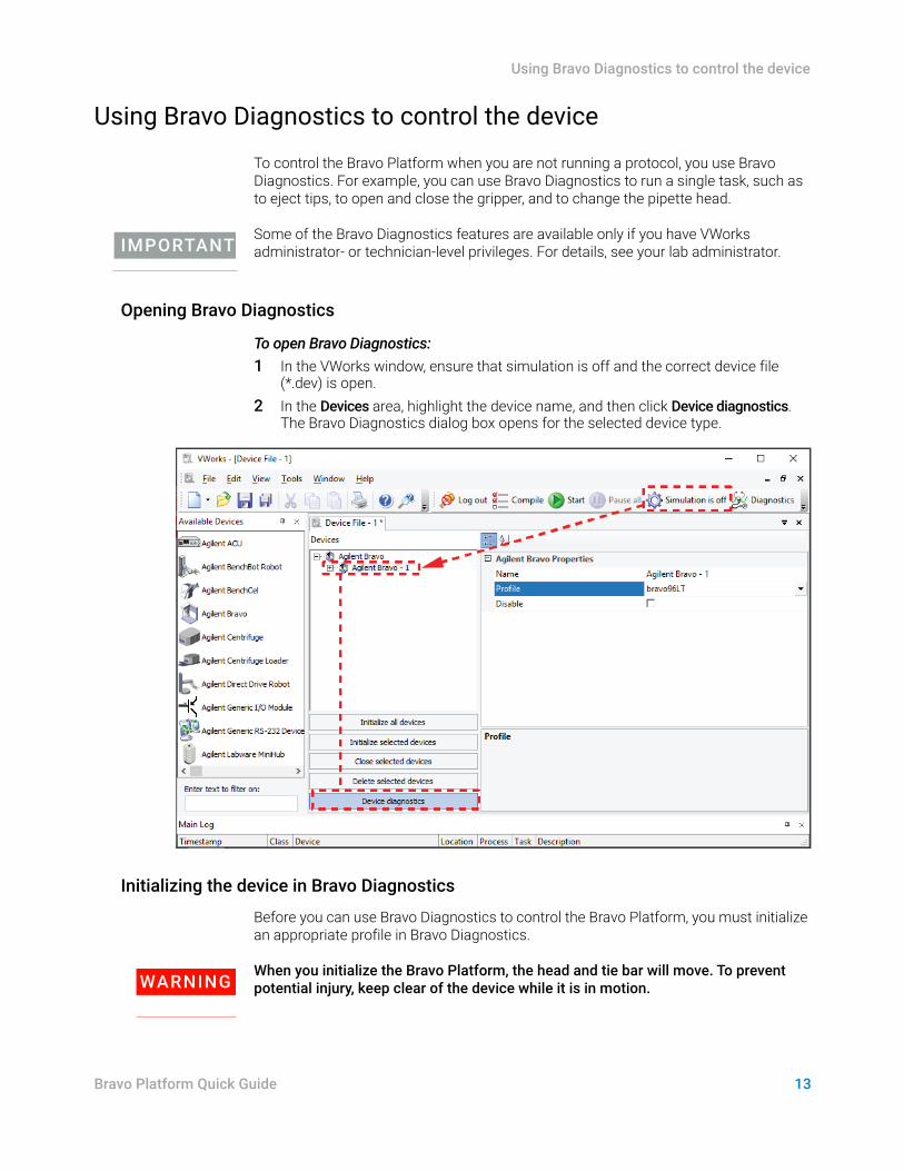
To open Bravo Diagnostics:1 In the VWorks window, ensure that simulation is off and the correct device file
(*.dev) is open.2 In the Devices area, highlight the device name, and then click Device diagnostics.
The Bravo Diagnostics dialog box opens for the selected device type.
Initializing the device in Bravo Diagnostics
Before you can use Bravo Diagnostics to control the Bravo Platform, you must initialize an appropriate profile in Bravo Diagnostics.
WARNINGWhen you initialize the Bravo Platform, the head and tie bar will move. To prevent potential injury, keep clear of the device while it is in motion.
Using Bravo Diagnostics to control the device
14 Bravo Platform Quick Guide
CAUTIONTo prevent potential equipment damage, ensure that the deck is clear of any obstacles before using the Bravo Platform.
CAUTIONUsing an incorrect profile can damage the Bravo Platform. Ensure that the profile is correct for the head type and deck configuration.
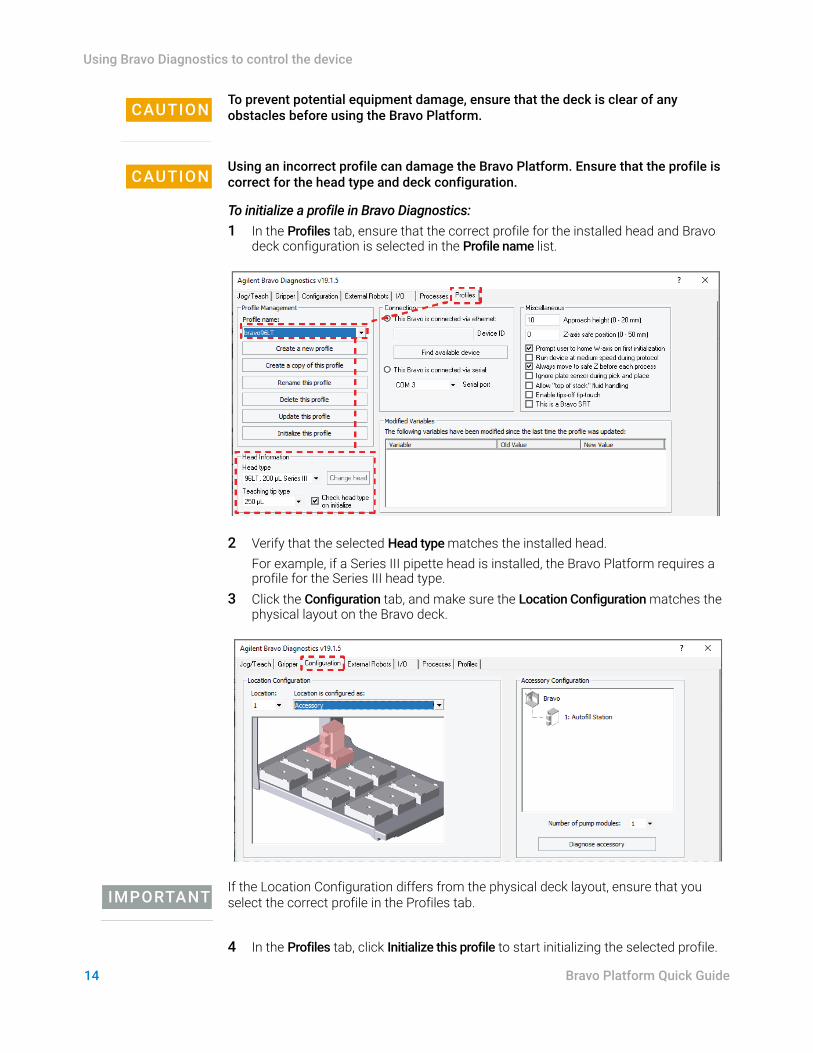
To initialize a profile in Bravo Diagnostics:1 In the Profiles tab, ensure that the correct profile for the installed head and Bravo
deck configuration is selected in the Profile name list.
2 Verify that the selected Head type matches the installed head.For example, if a Series III pipette head is installed, the Bravo Platform requires a profile for the Series III head type.
3 Click the Configuration tab, and make sure the Location Configuration matches the physical layout on the Bravo deck.
IMPORTANTIf the Location Configuration differs from the physical deck layout, ensure that you select the correct profile in the Profiles tab.
4 In the Profiles tab, click Initialize this profile to start initializing the selected profile.
15
Using Bravo Diagnostics to control the device
Bravo Platform Quick Guide
Running a task using Bravo Diagnostics
Before you start:• Place the labware for the task at the Bravo deck location or locations.• Ensure that the correct profile is initialized in Bravo Diagnostics. See “Initializing the
device in Bravo Diagnostics” on page 13.• Ensure that the emergency-stop pendant is connected properly.Refer to the following figure for this procedure.
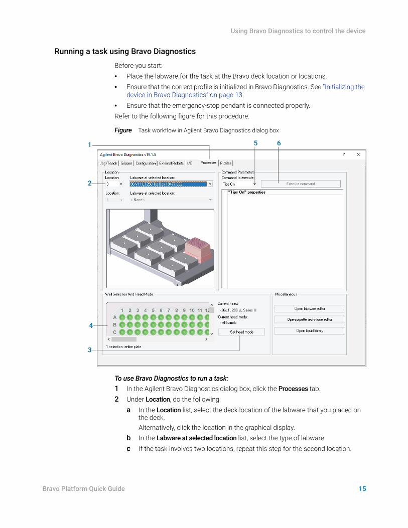
Figure Task workflow in Agilent Bravo Diagnostics dialog box
To use Bravo Diagnostics to run a task:1 In the Agilent Bravo Diagnostics dialog box, click the Processes tab.2 Under Location, do the following:
a In the Location list, select the deck location of the labware that you placed on the deck.Alternatively, click the location in the graphical display.
b In the Labware at selected location list, select the type of labware.c If the task involves two locations, repeat this step for the second location.
Using Bravo Diagnostics to control the device
16 Bravo Platform Quick Guide
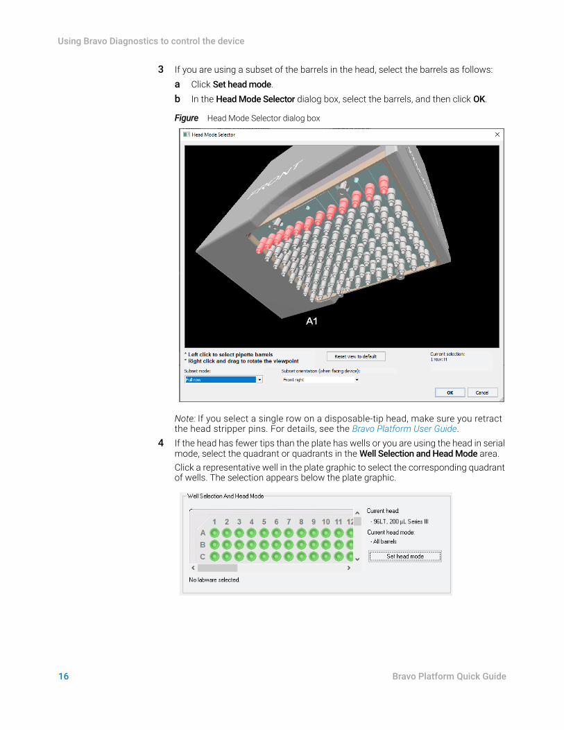
3 If you are using a subset of the barrels in the head, select the barrels as follows:a Click Set head mode. b In the Head Mode Selector dialog box, select the barrels, and then click OK.
Figure Head Mode Selector dialog box
Note: If you select a single row on a disposable-tip head, make sure you retract the head stripper pins. For details, see the Bravo Platform User Guide.
4 If the head has fewer tips than the plate has wells or you are using the head in serial mode, select the quadrant or quadrants in the Well Selection and Head Mode area.Click a representative well in the plate graphic to select the corresponding quadrant of wells. The selection appears below the plate graphic.
17
Changing the Bravo head
Bravo Platform Quick Guide
5 In the Command Parameters area:a Select the task from the Command to execute list.b Set the parameter values for the command. For details on setting the
parameter values, see the Bravo Platform User Guide or the VWorks Automation Control User Guide.
6 To start the task, click Execute command.
Changing the Bravo head
Use the following procedure to remove the currently installed head, install a different head, and adjust the corresponding settings in the VWorks software.
Before you start
WARNINGAssayMAP Bravo Platform only. To prevent potential injury from exposure to chemical spills, ensure that the syringes in the Bravo 96AM Head are empty before uninstalling the head. For instructions on how to change the 96AM Head, see the AssayMAP Bravo Platform Getting Started Guide.
CAUTIONAlways turn off the Bravo Platform before removing a head. Failure to turn off the Bravo Platform before changing the head can damage the head electronics.
CAUTIONDo not rest the bottom of a liquid-handling head on any surface. Doing so can damage the barrels, pins, or probes.
CAUTIONTo prevent potential contamination, do not touch the liquid-handling head barrels, tips, or probes with your hands.
IMPORTANTIf a head is being used for the first time, make sure you have an appropriate profile and device file for the new head. If necessary, contact your lab administrator to create a new profile and device file before starting the following procedure.
Ensure that the currently installed head does not have tips on the barrels. If necessary, use the Tips Off command in Bravo Diagnostics to remove the tips before removing the head. For details, see “Running a task using Bravo Diagnostics” on page 15.
Changing the Bravo head
18 Bravo Platform Quick Guide
Changing the mounted head
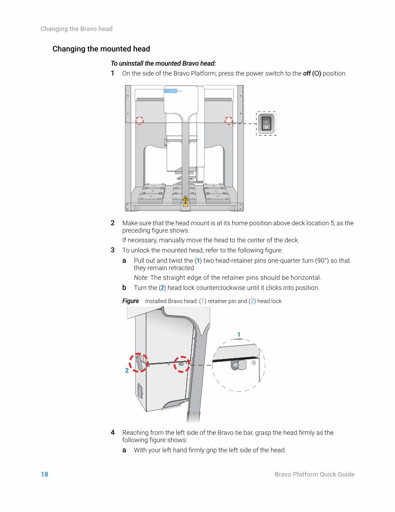
To uninstall the mounted Bravo head:1 On the side of the Bravo Platform, press the power switch to the off (O) position.
2 Make sure that the head mount is at its home position above deck location 5, as the preceding figure shows. If necessary, manually move the head to the center of the deck.
3 To unlock the mounted head, refer to the following figure:a Pull out and twist the (1) two head-retainer pins one-quarter turn (90°) so that
they remain retracted. Note: The straight edge of the retainer pins should be horizontal.
b Turn the (2) head lock counterclockwise until it clicks into position.
Figure Installed Bravo head: (1) retainer pin and (2) head lock
4 Reaching from the left side of the Bravo tie bar, grasp the head firmly as the following figure shows:a With your left hand firmly grip the left side of the head.
BravoBravo
2
1
19
Changing the Bravo head
Bravo Platform Quick Guide
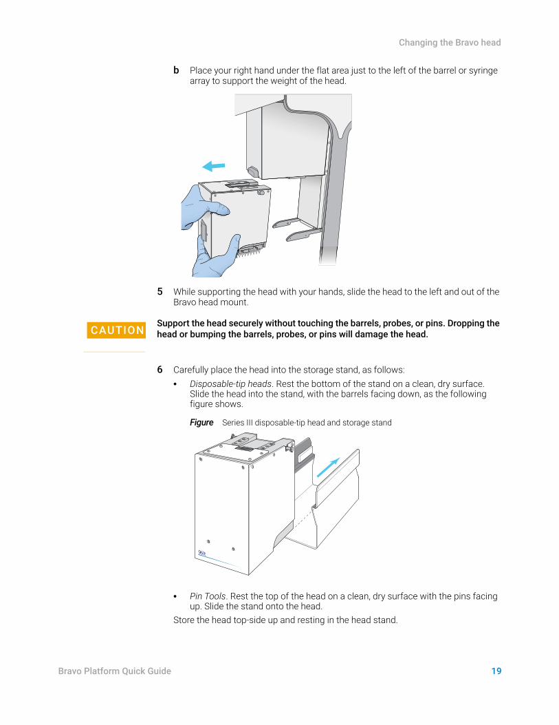
b Place your right hand under the flat area just to the left of the barrel or syringe array to support the weight of the head.
5 While supporting the head with your hands, slide the head to the left and out of the Bravo head mount.
CAUTIONSupport the head securely without touching the barrels, probes, or pins. Dropping the head or bumping the barrels, probes, or pins will damage the head.
6 Carefully place the head into the storage stand, as follows: • Disposable-tip heads. Rest the bottom of the stand on a clean, dry surface.
Slide the head into the stand, with the barrels facing down, as the following figure shows.
Figure Series III disposable-tip head and storage stand
• Pin Tools. Rest the top of the head on a clean, dry surface with the pins facing up. Slide the stand onto the head.
Store the head top-side up and resting in the head stand.
96lt
Changing the Bravo head
20 Bravo Platform Quick Guide
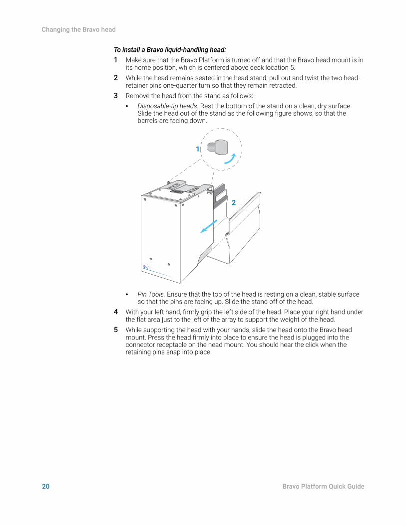
To install a Bravo liquid-handling head:1 Make sure that the Bravo Platform is turned off and that the Bravo head mount is in
its home position, which is centered above deck location 5. 2 While the head remains seated in the head stand, pull out and twist the two head-
retainer pins one-quarter turn so that they remain retracted. 3 Remove the head from the stand as follows:
• Disposable-tip heads. Rest the bottom of the stand on a clean, dry surface. Slide the head out of the stand as the following figure shows, so that the barrels are facing down.
• Pin Tools. Ensure that the top of the head is resting on a clean, stable surface so that the pins are facing up. Slide the stand off of the head.
4 With your left hand, firmly grip the left side of the head. Place your right hand under the flat area just to the left of the array to support the weight of the head.
5 While supporting the head with your hands, slide the head onto the Bravo head mount. Press the head firmly into place to ensure the head is plugged into the connector receptacle on the head mount. You should hear the click when the retaining pins snap into place.
96LT
1
2
21
Changing the Bravo head
Bravo Platform Quick Guide
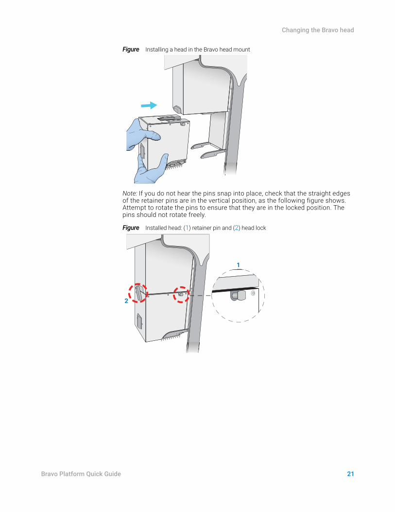
Figure Installing a head in the Bravo head mount
Note: If you do not hear the pins snap into place, check that the straight edges of the retainer pins are in the vertical position, as the following figure shows. Attempt to rotate the pins to ensure that they are in the locked position. The pins should not rotate freely.
Figure Installed head: (1) retainer pin and (2) head lock
2
1
Changing the Bravo head
22 Bravo Platform Quick Guide
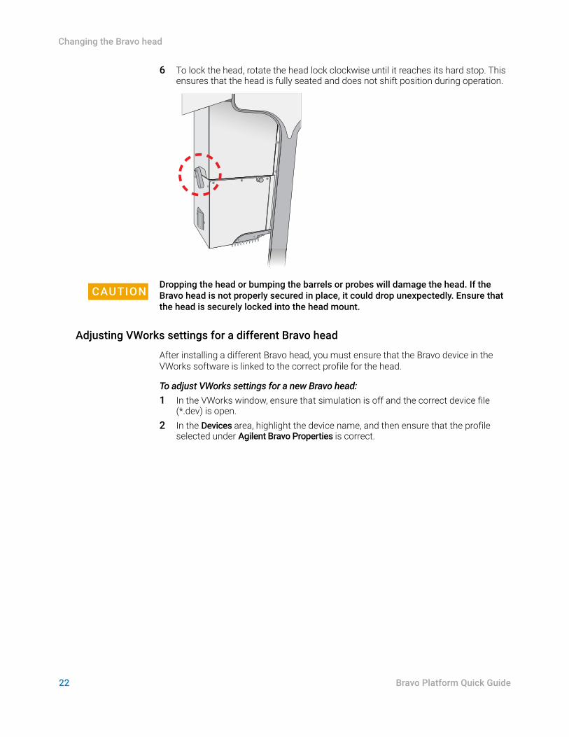
6 To lock the head, rotate the head lock clockwise until it reaches its hard stop. This ensures that the head is fully seated and does not shift position during operation.
CAUTIONDropping the head or bumping the barrels or probes will damage the head. If the Bravo head is not properly secured in place, it could drop unexpectedly. Ensure that the head is securely locked into the head mount.
Adjusting VWorks settings for a different Bravo head
After installing a different Bravo head, you must ensure that the Bravo device in the VWorks software is linked to the correct profile for the head.
To adjust VWorks settings for a new Bravo head:1 In the VWorks window, ensure that simulation is off and the correct device file
(*.dev) is open.2 In the Devices area, highlight the device name, and then ensure that the profile
selected under Agilent Bravo Properties is correct.
23
Changing the Bravo head
Bravo Platform Quick Guide
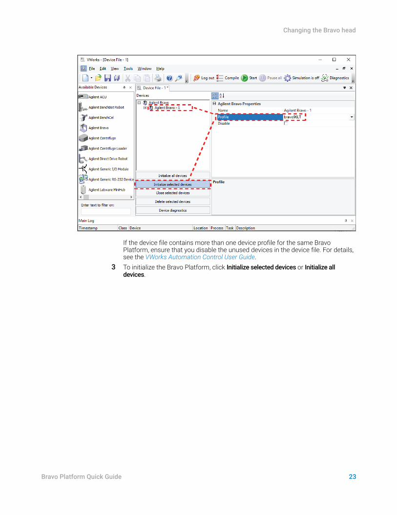
If the device file contains more than one device profile for the same Bravo Platform, ensure that you disable the unused devices in the device file. For details, see the VWorks Automation Control User Guide.
3 To initialize the Bravo Platform, click Initialize selected devices or Initialize all devices.

www.agilent.com© Agilent Technologies, Inc. 2019
September 2019
*SD-V1000642*
SD-V1000642 Revision B