bridge engineering seminar...bridge engineering seminar micropile foundations for bridges lexington,...
TRANSCRIPT

Micropile Foundations for Bridges
Bridge Engineering SeminarMicropile Foundations for BridgesLexington, KY
Dan Thome, P.E.
January 10, 2012

Micropiles
• OverviewInstallation Techniques• Installation Techniques
• Applications/Case Histories• Design• Design• Load Testing

Reasons for Deep Foundations
• Incompetent bearing layer• Total settlements and/or differential settlementsTotal settlements and/or differential settlements
can not be achieved with shallow foundations• Surface soil is subject to scour• Excavation will undermine existing shallow
foundations

Micropiles
• Description• 5 to 12 Inch diameter drilled and grouted5 to 12 Inch diameter drilled and grouted
piles• Can achieve capacities in Soil and Rock (250
tons)tons)• Develop primarily skin friction capacity• Ductile steel tubes (traditionally)• Depths over 200 feet (~330 feet)

Micropiles
• Advantages• Hole is typically cased until groutedHole is typically cased until grouted• Obstruction/rock drilling typically not an issue• Equipment could fit in 8 feet headroom and 3
f t dfoot doorways• Vibrations/noise less of an issue than with
other systems• Disadvantages
• Most expensive foundation system unless there are geotechnical or physical constraintthere are geotechnical or physical constraint

Typical Compression
Compressible Zone
B d ZBond Zone
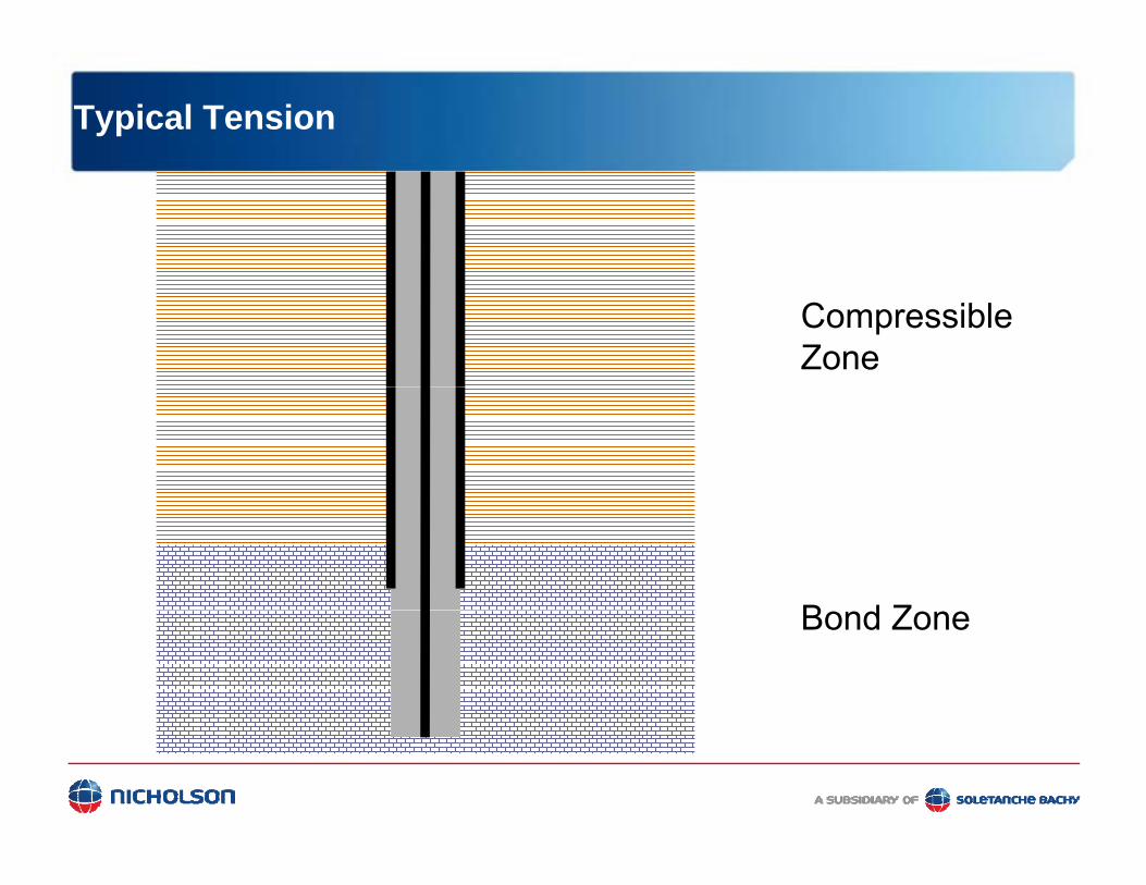
Typical Tension
Compressible Zone
B d ZBond Zone

Casing Only
Compressible Zone
Bond Zone
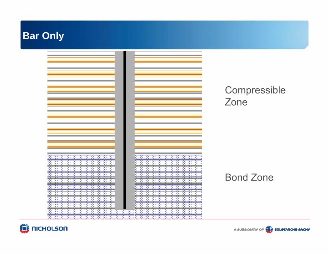
Bar Only
Compressible Zone
B d ZBond Zone
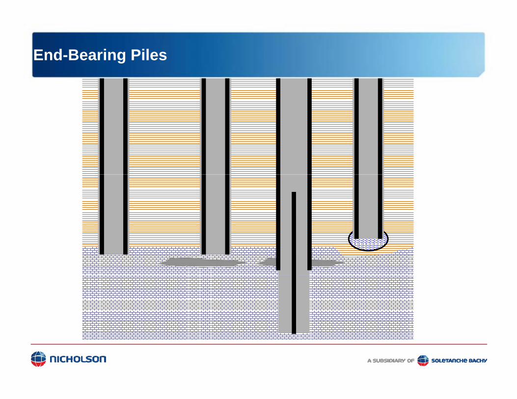
End-Bearing Piles

Materials – Steel Casing
• Use mill secondary oil field casing• Typically flush threaded joints yp y j• 80 ksi minimum yield strength

Materials – Reinforcing Bar
• Grade 60• Grade 75 or 80• Grade 150• Centralizers are used

Materials - Grout
• Neat cement with water/cement ratio of 0.45• Compressive strength of 4-6 ksip g• Improved stiffness w/confinement
Drilling Methods
• Proximity to other structures?• Soil stratigraphy?Soil stratigraphy?• Location of water table?• Soil gradation?Soil gradation?• Boulders/obstructions present?• Cost of spoil removal?Cost of spoil removal? • Total depth?
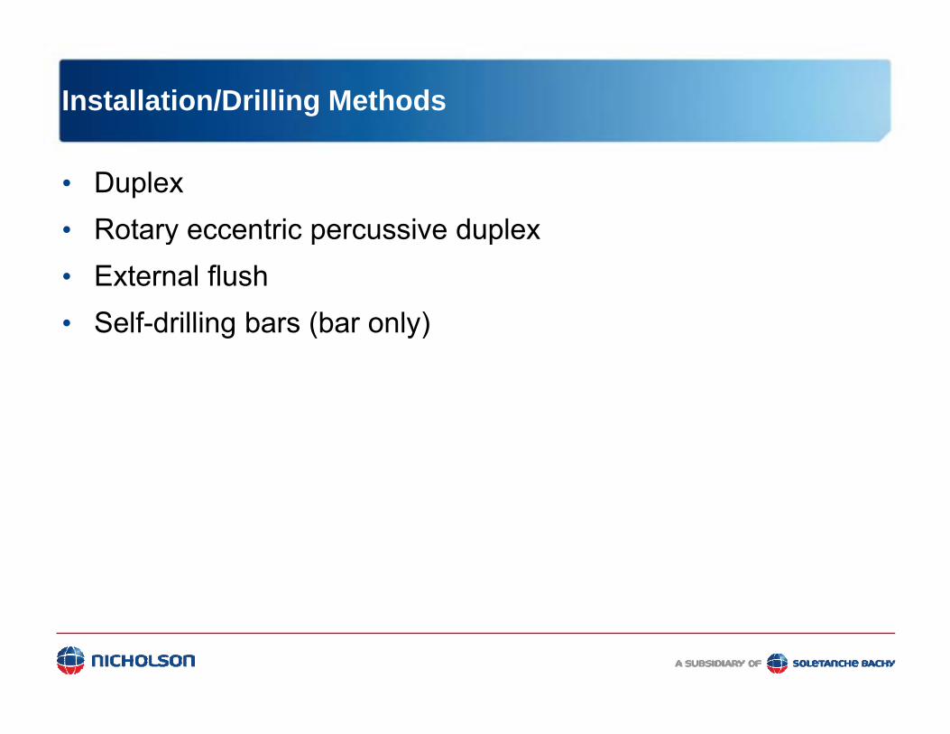
Installation/Drilling Methods
• Duplex• Rotary eccentric percussive duplex• Rotary eccentric percussive duplex• External flush• Self drilling bars (bar only)• Self-drilling bars (bar only)

Duplex Drilling

Duplex Drilling
• Often specified - least risk• Minimal loss of ground in
cohesionless soils• Grouted through the casing - then
pulled with tremie head or excess pressure
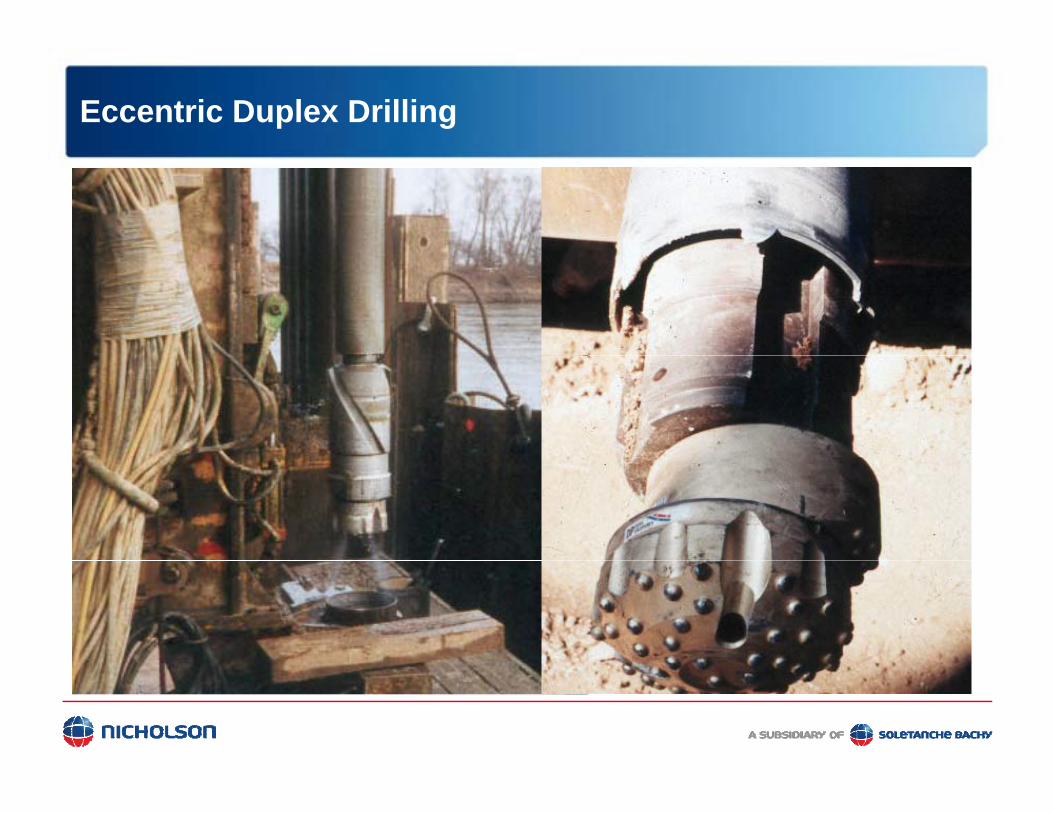
Eccentric Duplex Drilling

Eccentric Duplex Drilling
Top of Rock
Void
Bond Zone

External Flush Drilling
• Opening larger than casing size• Risk of ground loss in
cohesionless soils• Tremie grouted through casing
then pulled with tremie head or excess pressure

Applicationspp
New Structures in Difficult Ground

MDOT M-78 – Bellevue, MI

J.W. Marriott Parking Structure –Grand Rapids, MI

SR 33 – Stockertown, PA

Applicationspp
Additions to Existing Structures
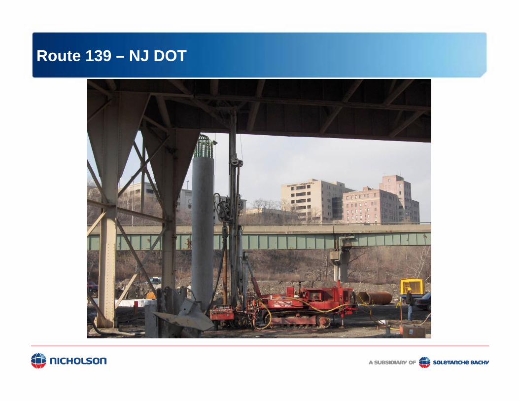
Route 139 – NJ DOT
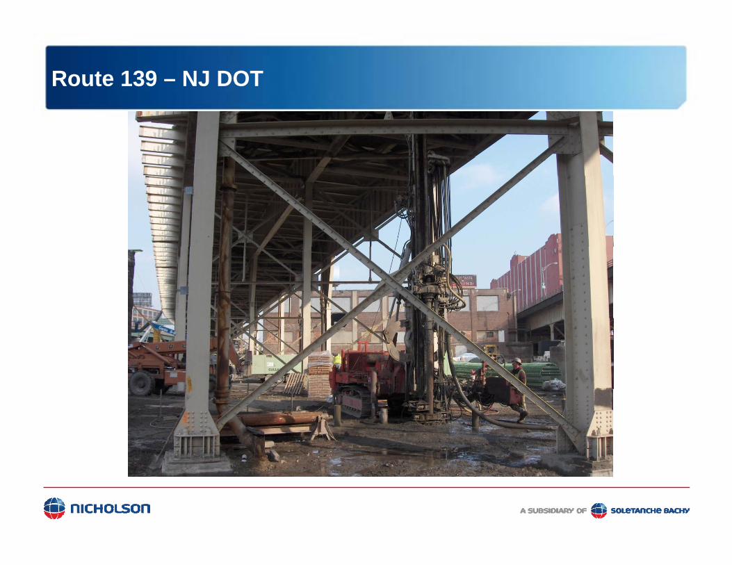
Route 139 – NJ DOT

Applicationspp
Rehabilitation of Existing Structures

MDOT I-94 - Project Background
• Original Construction (Late 1950s)• Two, three-span bridges for Interstate 94 over Riverside Drive• T-beam deck sections• Common partial height abutments• Abutments supported by shallow foundations on embankment fill• Abutments supported by shallow foundations on embankment fill• Piers supported by shallow foundations on native soils
• Reconstruction (Summer 2009)• Two, single span bridges• Common full height abutments
Both ab tments on dri en ‘H’ piles• Both abutments on driven ‘H’ piles
29

MDOT I-94 - Original Reconstruction Plan
New Pile Caps
E i ti
Phases III & IV Construction
Existing Shallow FdnsPhases I & II
Construction
Phases III & IV Construction
30

MDOT I-94 - Timeline of Events
• Mid April - Removal of bridge deck, piers and abutments for Phases I & II construction• April 30th – Pile driving with vibratory hammer begins for shallow depths• May 5th – Test piles are driven with impact hammer to LRFD refusal
• Estimated pile lengths ~ 90 to 100 feet
• Actual pile lengths ~ 140 feet• May 13th
Pil d i i i i h ib h f h ll d h• Pile driving continues with vibratory hammer for shallow depths
• MDOT observes:• Pavement cracks behind eastbound abutment (rotation of abutments towards Riverside Drive)• Settlement of existing piers (towards centerline of I-94)• Settlement of Riverside Drive (~ 1 foot concluded)
• Pile driving discontinued with vibratory hammer (~ 51 piles installed)• May 14th
MDOT b l t l hift f tb d Pi 2 ( 6 i h )• MDOT observes lateral shift of eastbound Pier 2 (~ 6 inches)
• Shutdown EB and WB lanes of Interstate 94 (WB lanes reopened on May 15th)
• Per MDOT, Nicholson visited site to observe movements• May 15th – MDOT contracted Nicholson to perform an emergency micropile retrofit of the existing eastbound
31
May 15 MDOT contracted Nicholson to perform an emergency micropile retrofit of the existing eastbound pier footings and perform real-time monitoring of the two bridges

MDOT I-94 - Timeline of Events
32
Westbound Lane – Looking Northeast

MDOT I-94 - Timeline of Events
33
Eastbound Lane – Looking South

MDOT I-94 - Timeline of Events
34
Eastbound Lane – Looking Northwest

MDOT I-94 - Emergency Micropile Retrofit – Pile Layout
NN
Phases III & IV Construction
Phases I & II Construction
35

MDOT I-94 - Emergency Micropile Retrofit – Pile Detail
36

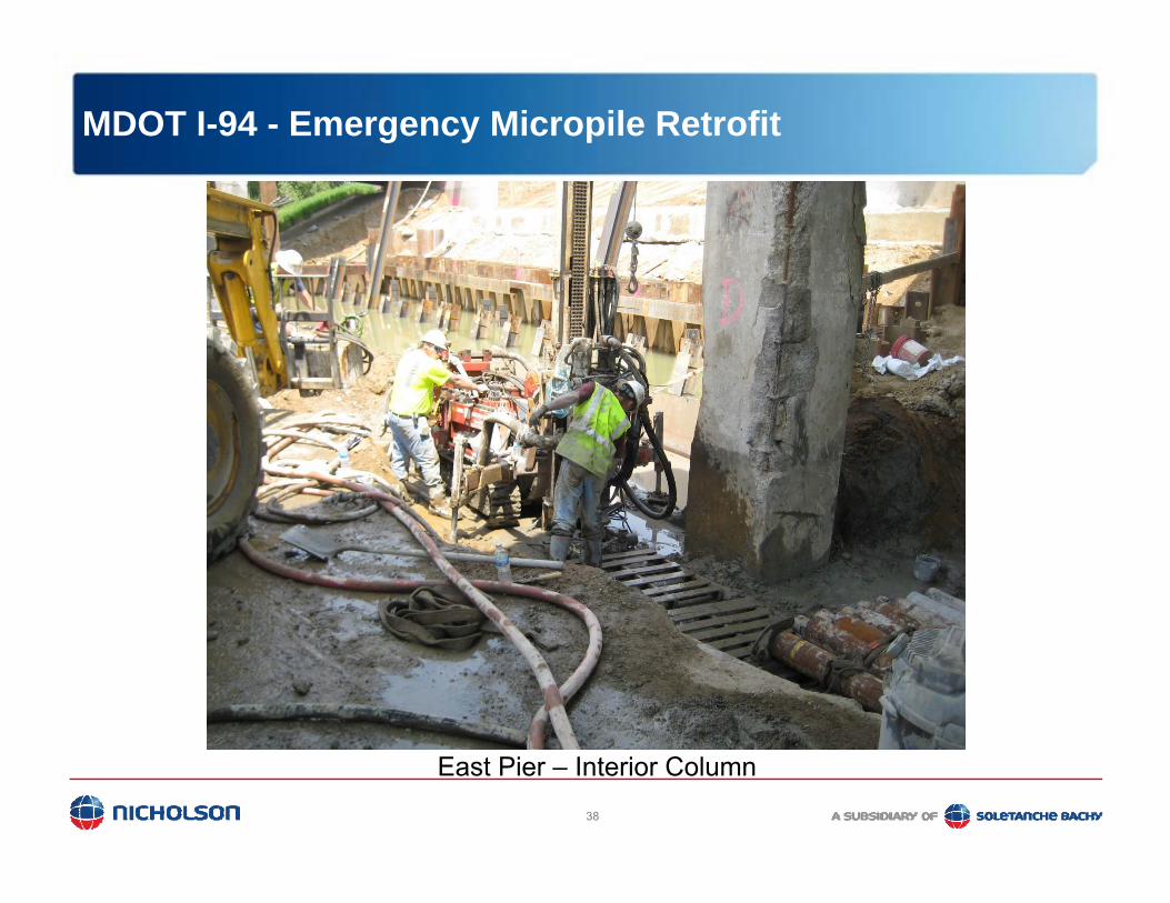
MDOT I-94 - Emergency Micropile Retrofit
37
West Pier – Interior Column
MDOT I-94 - Emergency Micropile Retrofit
38
East Pier – Interior Column

MDOT I-94 - Emergency Micropile Retrofit
39
West Pier – Interior Column

Micropile Design Aspects
• Geotechnical• Frictional bond• Frictional bond
compression & tension• End bearingg
• Structural• Lateral loads/bendingg• Battered piles/axial• Connection

FHWA – Allowable Compression
Pallc = 0.40 * fc * Agrout
+ 0.47 * fycasing * Acasing
+ 0.47 * fybar * Abar
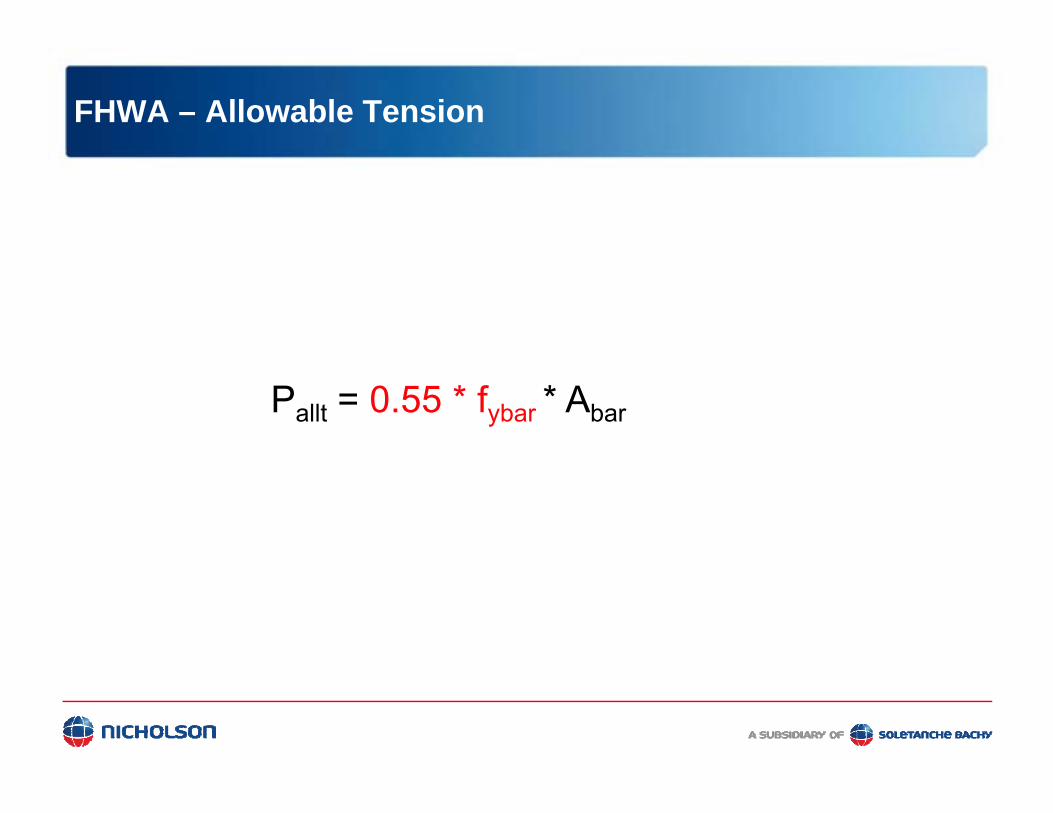
FHWA – Allowable Tension
Pallt = 0.55 * fybar * Abar

0 50 100 150 200 250 300 350 400 450 500
Allowable Load in KipsCode0 50 100 150 200 250 300 350 400 450 500
ACI with LF = 1.55
FHWA Micropiles
AASHTO Caisson
AASHTO Driven Unfilled
AASHTO Driven Concrete Filled
AREA Driven CIP Concrete
AREA Drilled ShaftsAREA Drilled Shafts
MASS BLDG CODE
City of Chicago
IBC2000 & BOCA Drilled uncased piles
IBC2000 Concrete filled pipe piles > 8"
IBC2000 Concrete filled pipe piles
IBC2000 Caisson Piles > 18"
BOCA Concrete filled pipe piles > 8"p p p
UBC 1808.2.2 Uncased CIP Concrete Piles
UBC 1808.3.2 Metal Cased Concrete Piles
UBC 1808.7.2 Concrete-filled Pipe Piles
UBC 1808 7 2 Concrete filled Pipe PilesUBC 1808.7.2 Concrete-filled Pipe Piles
7”OD x 0.5” wall casing with 5 ksi grout

Geotechnical Design
• Typical friction pile• Tip resistance neglectedTip resistance neglected• Pall = σπdL• where:where:• σ = Allowable bond stress
of Soil/Rock in bond zone (F.S. = 2.0 or 2.5)
• d = Diameter of bond zone
• L = Length of bond zone L
D
D

Bond Stress Recommendations
FHWA
1 kPa = 0.145 psip

Bond Stress PTI Recommendations

Bond Stress PTI Recommendations
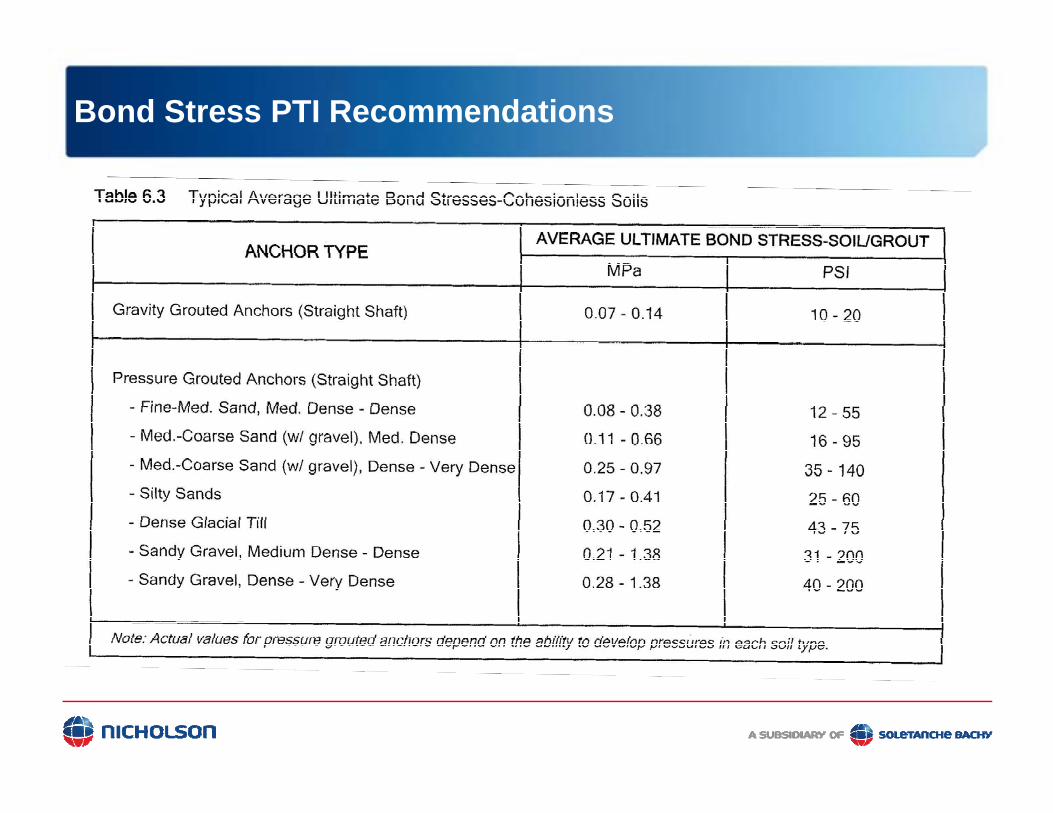
Bond Stress PTI Recommendations

Lateral Load Analysis
• Batter piles
• NAVFAC procedure
• LPILE to determine bending moment• LPILE to determine bending moment
• GROUP5 considers effect of batter
• Combined stress = axial load + bending

Simple Compression, New Footing
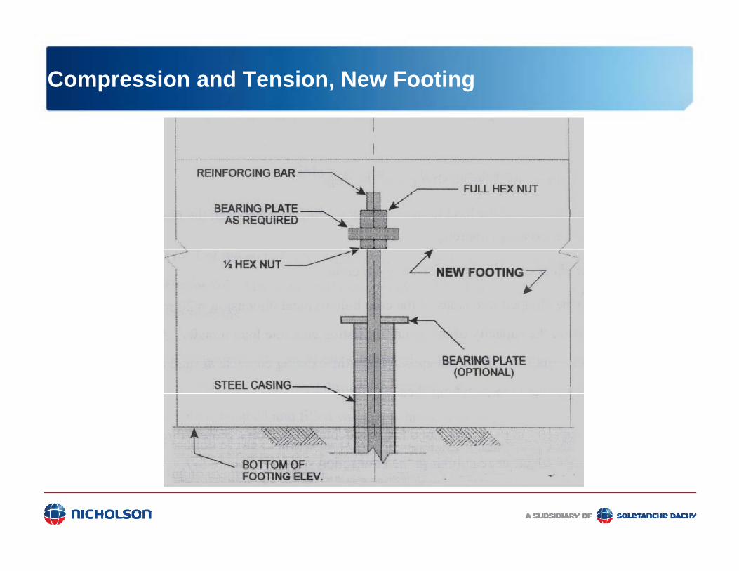
Compression and Tension, New Footing


Existing Footing Connection

Pile Load Testing
• Compression – ASTM D1143
T i ASTM D3689• Tension – ASTM D3689
• Lateral – ASTM 3966

Compression Test

Tension Test

Lateral Load Test
• Test 2 Piles
• Jack & Load Cell• Jack & Load Cell • between 2 piles
H d P• Hand Pump • small load
increments

Load Test Acceptance Criteria -FHWA Micropile Guidelines
• The pile shall sustain the compression and tension design loads (100% DL) with no more than ______ i h t t l ti l t t th t f th ilinches total vertical movement at the top of the pile.
• The slope of the pile deflection curve at twice the allowable design load is less than a slope of 0.15 mmallowable design load is less than a slope of 0.15 mm per kN (0.05 in / Ton) of applied load.
• Creep at Test Load of 0.04 inches 1 to 10 min or 0.08 inch/log cycleinch/log cycle

Thank You