bridge navigational watchkeepers alarm system - uk 150 manual... · bnwas 150 is designed for...
TRANSCRIPT
Manual BNWAS150 Iss01 Rev00
AMI MARINE (UK) LTD
BRIDGE NAVIGATIONAL WATCH ALARM SYSTEM (BNWAS)
BNWAS150
© This Manual and the information contained therein is the property of AMI Marine (UK) Ltd. It must not be reproduced or otherwise disclosed without prior consent in writing from AMI Marine (UK) Ltd

BNWAS150 - Bridge Navigational Watch Alarm System
Page 1 of 56
Manual BNWAS150 Iss01 Rev00
This Page Intentionally Blank

BNWAS150 - Bridge Navigational Watch Alarm System
Page 2 of 56
Manual BNWAS150 Iss01 Rev00
Document Revision
Date Modification Number (where applicable) Brief Record of Change and Reason for Change
Iss1 Rev0 06.02.12 Original Issue
NOTE: All alterations must be verified by re-authorisation and approval of the complete document. AMI MARINE (UK) LTD Unit 2 Tower Industrial Estate Tower Lane Eastleigh Southampton SO50 6NZ United Kingdom Tel No: +44 (0) 23 8048 0450 Fax No: +44 (0) 23 8065 1126 Email: [email protected] Web: www.amimarine.net

BNWAS150 - Bridge Navigational Watch Alarm System
Page 3 of 56
Manual BNWAS150 Iss01 Rev00
This page Intentionally Blank

BNWAS150 - Bridge Navigational Watch Alarm System
Page 4 of 56
Manual BNWAS150 Iss01 Rev00
IMPORTANT WARNINGS
DANGER!
RISK OF ELECTRICAL SHOCK!
Disconnect from the power before removing protective covers. DO NOT remove the covers while the unit is switched on.
24/12 Volt DC electrical power on external units.
NOTICE Compass safe distance is 1 metre.
NOTICE No user serviceable parts inside, servicing only by properly qualified
and certified technical staff.
NOTICE This manual is for informational use only, and may be changed without notice. This manual should not be construed as a commitment of AMI Marine (UK) Ltd. Under no circumstances does AMI Marine (UK) Ltd assume any responsibility or liability for any errors or inaccuracies that may appear in this document. The equipment should only be used for the purposes intended by the manufacturer; any deviation from this will void the warranty of the product.

BNWAS150 - Bridge Navigational Watch Alarm System
Page 5 of 56
Manual BNWAS150 Iss01 Rev00
This page Intentionally Blank

BNWAS150 - Bridge Navigational Watch Alarm System
Page 6 of 56
Manual BNWAS150 Iss01 Rev00
CONTENTS - Foreword ....................................................................................................................... 8 - Introduction to BNWAS ................................................................................................. 9 - BNWAS 150 System Overview ................................................................................... 14 - System Components ................................................................................................... 16 - BNWAS 150 Controls and Functions .......................................................................... 17 - Equipment Specifications ............................................................................................ 19
Display Control Panel - DC-150 ............................................................................. 19 Distribution Interface Unit - DU-150 ....................................................................... 20 Reset Push Button - RI-150 ................................................................................... 22 Reset Push Button with Buzzer - RE-150 .............................................................. 23 Passive Infra-Red (PIR) Detectors Motion Sensors - MD-150 ............................... 24 Alarm Sounders and Sounder Beacons - SD-150 and SB-150 .............................. 25
- Equipment Description ................................................................................................ 26 - Equipment Connection ................................................................................................ 29
- Equipment Assembly and Internal Connection .................................................... 34 - Software Setup and Operation .................................................................................... 35
Switching On The BNWAS 150 .............................................................................. 35 Entering Setup ....................................................................................................... 37 Mode Selection ...................................................................................................... 38 Stage 2 to Stage 3 Delay ....................................................................................... 38 Initial Dormant Period ............................................................................................ 38 Operational Sequence ........................................................................................... 39 Selecting Duty Cabins and Using Cabin Call ......................................................... 40 External Reset ....................................................................................................... 41 Unacknowledged Alarms ....................................................................................... 42
- System Faults ............................................................................................................. 43 - Maintenance guide ...................................................................................................... 44 - Warranty Card ............................................................................................................. 55

BNWAS150 - Bridge Navigational Watch Alarm System
Page 7 of 56
Manual BNWAS150 Iss01 Rev00
This page Intentionally Blank

BNWAS150 - Bridge Navigational Watch Alarm System
Page 8 of 56
Manual BNWAS150 Iss01 Rev00
- Foreword For over 15 years AMI Marine (UK) Ltd has enjoyed an enviable reputation for innovative and reliable marine electronics equipment. This dedication to excellence is enhanced by our extensive global network of service agents and dealers. The BNWAS 150 has been designed and constructed to meet the rigorous demands of the marine environment. However, no equipment can perform its intended function unless installed, operated and maintained correctly. Please carefully read and follow the recommended procedures for installation, operation, and maintenance. BNWAS 150 is designed for maintenance free operation providing fast, accurate information for the lifetime of the vessel. It is simple to use, straight forward to learn and easy to operate. Human Machine Interface - The BNWAS 150 unit provides a tamper proof interface for communication with its sensors. The system’s parameters and operation can be initialised and controlled via a simple LCD based navigation menu. The menu is key locked and should have access restricted, as directed by the ship’s Master. Various indications are signalled on the display control panel that indicate to the personnel on the bridge the status of the system and any action that may be required. Alarms– There are 3 stages of alarm that are sequentially activated. Each stage activates alarm sounders in required locations of the vessel to notify off watch personnel that the bridge is no longer manned, and that immediate action is required.

BNWAS150 - Bridge Navigational Watch Alarm System
Page 9 of 56
Manual BNWAS150 Iss01 Rev00
- Introduction to BNWAS
MARITIME NAVIGATION AND RADIOCOMMUNICATION EQUIPMENT AND SYSTEMS –
BRIDGE NAVIGATIONAL WATCH ALARM SYSTEM (BNWAS)
The International Standard IEC62616-Ed1 specifies the minimum performance requirements, technical characteristics and methods of testing, and required test results, for a bridge navigational watch alarm system (BNWAS) as required by Chapter V of the International Convention for the Safety of Life at Sea (SOLAS), as amended. It takes account of the general requirements given in IMO resolution A.694(17) and is associated with IEC 60945. When a requirement in this International Standard is different from IEC 60945, the requirement in this standard takes precedence. The standard incorporates the parts of the performance standards included in IMO resolution MSC.128(75). All text of the standard, whose wording is identical to that of IMO resolution MSC.128(75), is printed in italics, and the resolution and associated performance standard paragraph numbers are indicated in brackets. (128/A1) The purpose of a bridge navigational watch alarm system (BNWAS) is to monitor bridge activity and detect operator disability which could lead to marine accidents. The system monitors the awareness of the Officer of the Watch (OOW) and automatically alerts the Master or another qualified OOW if for any reason the OOW becomes incapable of performing the OOW's duties. This purpose is achieved by a series of indications and alarms to alert first the OOW and, if he is not responding, then to alert the Master or another qualified OOW. Additionally, the BNWAS may provide the OOW with a means of calling for immediate assistance, if required. The BNWAS should be operational whenever the ship is underway at sea (SOLAS V/19.2.2.3). The IMO Committee approved the draft amendments to the SOLAS Regulation that requires the mandatory carriage of a bridge navigation watch alarm system for the subsequent adoption at the MSC 86. (Amendments to the SOLAS Reg. V/19 - Carriage requirements for a bridge navigational watch alarm system) Application: The amendments stipulate as follows: 1st July 2011 on or after for all new builds of 150 gt or over - (keel lay base) Ships constructed prior to 1st July 2011 will have to fit the BNWAS by the 1st survey after: 1st July 2012 for cargo ships of 3000 gt or over and all passenger ships. 1st July 2013 for cargo ships of 500 gt or over but less than 3000 gt. 1st July 2014 for cargo ships of between 150 gt or over but less than 500 gt. These requirements also apply to ships not engaged on international voyages.

BNWAS150 - Bridge Navigational Watch Alarm System
Page 10 of 56
Manual BNWAS150 Iss01 Rev00
3 Performance requirements 3.1 Functionality 3.1.1 Operational modes (128/A4.1.1.1) The BNWAS shall incorporate the following operational modes:
• Automatic (Automatically brought into operation whenever the ship's heading or track control system is activated and inhibited when this system is not activated)
• Manual ON (In operation constantly) • Manual OFF (Does not operate under any circumstances)
NOTE The Automatic mode is not suitable for use on a ship conforming to regulation SOLAS V/19.2.2.3 which requires the BWNAS to be in operation whenever the ship is underway at sea. 3.1.2 Operational sequence of indications and alarms 3.1.2.1 Dormant period (128/A4.1.2.1) Once operational, the alarm system shall remain dormant for a period of between 3 and 12 min (Td). See Table 1. (128/A4.1.2.2) At the end of this dormant period, the alarm system shall initiate a visual indication on the bridge.
Table 1 – Alarm sequence without acknowledgements 3.1.2.2 First stage bridge audible alarm (128/A4.1.2.3) If not reset, the BNWAS shall additionally sound a first stage audible alarm on the bridge 15 s after the visual indication is initiated.

BNWAS150 - Bridge Navigational Watch Alarm System
Page 11 of 56
Manual BNWAS150 Iss01 Rev00
3.1.2.3 Second stage remote audible alarm (128/A4.1.2.4) If not reset, the BNWAS shall additionally sound a second stage remote audible alarm in the back-up officer's and/or Master's location 15 s after the first stage audible alarm is initiated. 3.1.2.4 Third stage remote audible alarm (128/A4.1.2.5) If not reset, the BNWAS shall additionally sound a third stage remote audible alarm at the locations of further crew members capable of taking corrective actions 90 s after the second stage remote audible alarm is initiated. 3.1.2.5 Alarm alternatives (128/A4.1.2.6) In vessels other than passenger vessels, the second or third stage remote audible alarms may sound in all the above locations at the same time. If the second stage audible alarm is sounded in this way, the third stage alarm may be omitted. (128/A4.1.2.7) In larger vessels, the delay between the second and third stage alarms may be set to a longer value on installation, up to a maximum of 3 min, to allow sufficient time for the back-up officer and/or Master to reach the bridge. Installation set-up facilities shall be provided to inhibit the third stage alarm and to increase the delay between the second and third stage alarms to 3 min. 3.1.3 Reset function 3.1.3.1 Description of reset function (128/A4.1.3.2) The reset function shall, by a single operator action, cancel the visual indication and all audible alarms and initiate a further dormant period. If the reset function is activated before the end of the dormant period, the period shall be re-initiated to run for its full duration from the time of the reset. Single operator action is defined as activating a hard-key or soft-key including any necessary cursor movement. 3.1.3.2 Initiation of reset function (128/A4.1.3.3) To initiate the reset function, an input representing a single operator action by the OOW is required. This input may be generated by reset devices forming an integral part of the BNWAS or by external inputs from other equipment capable of registering physical activity and mental alertness of the OOW.

BNWAS150 - Bridge Navigational Watch Alarm System
Page 12 of 56
Manual BNWAS150 Iss01 Rev00
For the purposes of this standard, mental alertness means consciously intended operations or movements (for example performing a function available in the human-machine interface) for which there is no risk of automatic generation by vibration or by movement of the ship. NOTE The IMO subcommittee on the safety of navigation at its 55th session (NAV 55/21) described three methods for the reset function as follows: 1) by a single operator action from a device forming an integral part of the BNWAS, for example a manually operated button or
a touch screen; or 2) by external inputs from other equipment registering physical activity, for example sensors preferably detecting the presence
and movements of a human body or floor pressure pads detecting movement of a human; or 3) by external inputs from other equipment registering mental alertness of the OOW, for example speech recognition sensors
or changes in the operation of the manual controls of bridge equipment.
3.1.3.3 Continuous activation (128/A4.1.3.4) A continuous activation of any reset device shall not prolong the dormant period or cause a suppression of the sequence of indications and alarms. 3.1.4 Emergency call facility and transfer of alarms (128/A4.1.4) Means may be provided on the bridge to immediately activate the second, and subsequently third, stage remote audible alarms by means of an "Emergency Call" push button or similar. Installation set-up facilities shall be provided for an “Emergency Call” system. Facilities shall also be provided to immediately actuate the “Emergency Call” system from other equipment capable of transferring an unacknowledged alarm by contact closure or equivalent circuit, or an IEC 61162 interface using the ALR sentence. NOTE Examples of equipment which are capable of transferring alarms include Integrated Navigation Systems and Track Control Systems. IMO Resolution MSC.252(83), paragraph 20.5.1 states: After a time defined by the user unless otherwise specified by IMO, an unacknowledged alarm should be transferred to the bridge navigational watch alarm system (BNWAS), if available. The unacknowledged alarm should remain visible and audible. IMO Resolution MSC.74(69) annex 2, paragraph 5.3.4 states: In the case of any failure or alarm status received from the position-fixing sensor, the heading sensor or the speed sensor in use: 1) an alarm should be generated at the track control system; 2) the system should automatically provide guidance to the user of a safe steering mode; and 3) a back-up navigator alarm should be given if a failure or alarm status is not acknowledged by the officer of the watch (user) within 30s.

BNWAS150 - Bridge Navigational Watch Alarm System
Page 13 of 56
Manual BNWAS150 Iss01 Rev00
This page Intentionally Blank
BNWAS150 - Bridge Navigational Watch Alarm System
Page 14 of 56
Manual BNWAS150 Iss01 Rev00
- BNWAS 150 System Overview The BNWAS 150 system is designed for use on a vessel’s navigation bridge. The remote alarm sounders cover key locations such as the officer cabins, mess area and ship’s office. Reset devices can be used on the bridge wings. The display control and monitoring equipment is to be installed in protected areas inside the bridge. Dormant Time This function is adjustable between 3-12 minutes in 1 minute increments only whilst in SETUP mode. Remote Resets BNWAS 150 has a reset mechanism which can be activated by a combination of reset pushbuttons and PIR motion detection sensors. Fail Alerts BNWAS 150 has alert messages for Tamper, Power and Battery. Tamper alert is also audible by means of an on-board buzzer within the display control unit. Emergency Call and Cabin Call BNWAS 150 has an Officer call configurable in up to 5 officer cabins within the menu. Power supply BNWAS 150 is powered by two separate 24 Volt supplies (main and backup) which will automatically switch to the backup supply in the event of a main supply failure. This will raise an alarm. Inputs from Valid Reset Devices & System Alarms BNWAS 150 provides additional Digital Inputs to accept signals from other devices and transfer alarms. An external equipment in alarm will send a digital input to the BNWAS and the source will be shown on LCD display. These might include RADAR or ECDIS. External valid reset inputs must be approved by the appropriate approval body before being used. AMI Marine (UK) Ltd will assist with recommendations wherever possible from previous experience but will not accept responsibility if not accepted. BNWAS 150 comprises: Hardware consisting of - Control display panel, interface unit, physical and sensory reset devices, alarm sounders and beacons. The BNWAS 150 Software Navigation Menu where the Master can configure and control the operational mode and parameters of the system. Overall Layout There are three areas within the vessel were the system and peripheral units are fitted:- Wheel house / Bridge Accommodation Areas Remote Locations

BNWAS150 - Bridge Navigational Watch Alarm System
Page 15 of 56
Manual BNWAS150 Iss01 Rev00
Wheel house / Bridge Equipment - Control display, Stage 1 Alarm sounders, Alarm Beacon, Directional PIR’s, and push button reset switches. Push buttons can be mounted on the Bridge wing, and are IP rated accordingly. Accommodation Decks Equipment - Stage 2 Alarms are located in the accommodation area. The system is configurable through the navigation menu, for five separate accommodation rooms, labelled: Cabin 1, Cabin 2, Cabin 3, Cabin 4, Cabin 5 - (Captain, Officer 1, 2, 3 and 4) The alarm sounders or sounder beacons can be used. Remote Locations Equipment - Stage 3 Alarms are located in remote locations which could include Officer’s mess, Office locations and Engine Control Room. They can be alarm sounders or sounder beacons.

BNWAS150 - Bridge Navigational Watch Alarm System
Page 16 of 56
Manual BNWAS150 Iss01 Rev00
- System Components BNWAS 150 is made up of a number of component units including a central display control panel, reset pushbuttons, motion sensors and alarm sounders. This section provides both an overall view of the structure of the BNWAS 150 system and a description of the component units outlined in Table 1 Part Number Description DC-150 BNWAS Display Control Panel MD-150 BNWAS Passive Infra-red Detectors DU-150 BNWAS Distribution Interface Unit IC-150 BNWAS Interconnection Cable RI-150 BNWAS Illuminated Reset Pushbutton RE-150 BNWAS Illuminated Reset Pushbutton with Buzzer SD-150 BNWAS Alarm Sounders SB-150 BNWAS Alarm Sounders with Beacon Table 1: BNWAS 150 Components
DC-150 MD-150
DU-150 IC-150
RI-150 SD-150
RE-150 SB-150
111111111155555555555555555555550000000000000000000000000000000000
NOTE: Images Not To Scale

BNWAS150 - Bridge Navigational Watch Alarm System
Page 17 of 56
Manual BNWAS150 Iss01 Rev00
- BNWAS 150 Controls and Functions
DC-150 Display and Control The BNWAS DC-150 Display Control Panel is the user interface and display for the BNWAS150 The display control panel is to be mounted at a suitable location within the ship bridge preferably at a location where the watch officer is expected to be stationed during normal on watch operations
Figure 1 - DC-150 Control Display Panel
The Key switch has 2 positions which change the function of the tactile buttons; 1. RUN - Normal operation position where the system is monitoring all sensor inputs. 2. SETUP – To set the ‘Operational Mode’ and to adjust the timing parameters.
Automatic Dimming of the LCD Display A light detection sensor automatically dims the display at low light levels to prevent light pollution during night time operation.

BNWAS150 - Bridge Navigational Watch Alarm System
Page 18 of 56
Manual BNWAS150 Iss01 Rev00
RI-150 Illuminated Reset Pushbutton and RE-150 Illuminated Reset Pushbutton with Buzzer The RI-150 reset pushbutton unit can be used to reset the BNWAS system’s timer before or during the 1st stage alarm. The RE-150 unit performs the same function but also has an audible alarm making it ideal for use on the bridge wings.
SD-150 Alarm Sounder and SB-150 Sounder Beacon The SD-150 alarm sounders are used for the 2nd or 3rd stage alarms and have adjustable volume between 85 and 105dB. The SB-150 performs the same function but also has a highly visible LED indication.
Figure 3 - RE-150 Illuminated Reset Pushbutton with Buzzer
Figure 2 - RI-150 Illuminated Reset Pushbutton
Figure 4 - SD-150 Alarm Sounder
Figure 5 - SD-150 Sounder Beacon

BNWAS150 - Bridge Navigational Watch Alarm System
Page 19 of 56
Manual BNWAS150 Iss01 Rev00
- Equipment Specifications
Display Control Panel - DC-150
Figure 6: BNWAS DC-150 Display Control Panel Front
The Display Control Panel – Comprises a backlit LCD display, audible and visual alarm, setup / run key switch and 3 button tactile keypad for Reset, Emergency Call and Setup functions. DC-150 Display Control Panel Specifications
Power:- Nominal 24VDC Dimensions:- 150mm x 80mm x 45mm (W x H x D) Material:- ABS – Halogen Free Properties:- Ingress protection: IP52 Operating Temperature -25°C to +55°C Automatic Dimming for Night Vision

BNWAS150 - Bridge Navigational Watch Alarm System
Page 20 of 56
Manual BNWAS150 Iss01 Rev00
Distribution Interface Unit - DU-150
Figure 7 - DU-150 Distribution Interface Unit
View from underneath
Figure 8 - DU-150 Distribution Interface Unit View from behind

BNWAS150 - Bridge Navigational Watch Alarm System
Page 21 of 56
Manual BNWAS150 Iss01 Rev00
Figure 9 - DU-150 Distribution Interface Unit
Side view
DU-150 Junction Box Specifications Dimensions:- 254mm x 180mm x 90mm (W x H x D) Material: - Base and Cover: Polystyrene Properties: - Ingress protection: IP66 - acc. EN 60529 / DIN VDE 0470-1 Operating Temperature: - -20°C to 40°C Halogen-free 3m Interconnection Cable (IC-150) to DC-150

BNWAS150 - Bridge Navigational Watch Alarm System
Page 22 of 56
Manual BNWAS150 Iss01 Rev00
Reset Push Button - RI-150 The BNWAS 150 reset pushbutton module is used to indicate operator alertness to the system. The reset button must be pressed every 3-12 minutes (or before) as configured by the Master. The reset pushbutton module houses a Red illuminated pushbutton with 1 normally open contact.
Figure 10 - BNWAS RI-150 Reset Pushbutton
RI-150 Push Button Specifications Power 12VDC Dimensions:- RI-150 = 94mm x 94mm x 81mm (W x H x D) Material: - Base and Cover: Polycarbonate, glass-fibre reinforced Properties: - Ingress protection: IP66 - acc. EN 60529 / DIN VDE 0470-1 Operating Temperature: - -35°C to 80°C Halogen-free

BNWAS150 - Bridge Navigational Watch Alarm System
Page 23 of 56
Manual BNWAS150 Iss01 Rev00
Reset Push Button with Buzzer - RE-150 The BNWAS 150 reset pushbutton module is used to indicate operator alertness to the system. The reset button must be pressed every 3-12 minutes (or before) as configured by the Master. The reset pushbutton module houses a Red illuminated pushbutton with 1 normally open contact. A built in buzzer provides additional alert when reset is required, making it idea for use on bridge wings
Figure 11 - BNWAS RE-150 Reset Pushbutton with Buzzer
RI-150 Push Button Specifications Power: 12VDC Dimensions:- RE-150 = 94mm x 130mm x 81mm (W x H x D) Material: - Base and Cover: Polycarbonate, glass-fibre reinforced Properties: - Ingress protection: IP66 - acc. EN 60529 / DIN VDE 0470-1 Operating Temperature: - -35°C to 80°C Halogen-free

BNWAS150 - Bridge Navigational Watch Alarm System
Page 24 of 56
Manual BNWAS150 Iss01 Rev00
Passive Infra-Red (PIR) Detectors Motion Sensors - MD-150
The BNWAS MD-150 Motion sensors are used to detect human presence by monitoring movement within the bridge area and reset the system timer.
Figure 12 - BNWAS MD-150 PIR Motion Sensor
MD-150 PIR Specifications
Power - 12 VDC at 18mA Dimensions:- 65 x 117 x 47 mm (W x H x D) Material:- Polystyrene Properties:- Ingress protection: IP54 Operating Temperature: - -20°C to 50°C Visual Indications - Steady red LED will illuminate for 2-3 seconds on detection of movement. Installation - Bulkhead surface or corner. Mounting Height - 1.8 to 2.4 m (6 to 8 ft.) Max. Coverage - 12 m (40 ft.) diagonal size / 90° Mass Immunity - Immune to objects weighing up to 36 kg (80 lb.) Vertical Adjustment - 3-position adjustment: 1.8 m (6 ft.), 2.1 m (7 ft.) and 2.4 m (8 ft.).

BNWAS150 - Bridge Navigational Watch Alarm System
Page 25 of 56
Manual BNWAS150 Iss01 Rev00
Alarm Sounders and Sounder Beacons - SD-150 and SB-150
The BNWAS 150 alarm sounders are to be configured in Bridge area(s), Officer Cabins and remote locations which might include passenger area(s), engine control room and officer mess. The Alarm sounders are tone selectable during commissioning in order to differentiate between different alarm sounds.
Figure 13 - SD-150 Sounder Figure 14 - SB-150 Sounder Beacon Figure 15 – Universal Base
SD-150 SB-150
Input Voltage 12V DC 12V DC
Input Current ~16mA ~68mA
Temp Range -10°C to +55°C -10°C to +55°C
Sound Pressure 85-102dB @ 1m, tone selectable 85-101dB@1m, tone selectable
Environmental Rating IP65 IP65
Note: Combinational Beacon/ Sounders are optional

BNWAS150 - Bridge Navigational Watch Alarm System
Page 26 of 56
Manual BNWAS150 Iss01 Rev00
- Equipment Description Installation guide Unpack BNWAS 150 System and peripherals verify all components as per Packing Specification. DC-150 Display Control Panel (ref Figure 6 - page 19) Identify suitable location for the BNWAS DC-150 Display Control Panel. Unscrew BNWAS 150 front panel by removing the 4 x corner covers and unscrewing the 4 x screws. Unplug the 40 way connector and place the front panel in a safe location. This will allow access to the wall mount holes. A 35mm hole should be made in the panel/console to allow the cable and 20mm gland to pass through. Once the display is sited in place mark up the securing holes and fit the back of the enclosure. DU-150 Distribution Interface Unit (ref Figure 7, 8 and 9 - page 20 and 21) Four holes are available for securing the rear of the enclosure to the selected surface. Knock out holes are available at the bottom, sides and top of the enclosure for installing glands through which cables will be passed. Once all wiring is completed as per the wiring schedule the enclosure lid should be secured using the four screws in the corners of the enclosure lid. RI-150 Reset Pushbutton (ref Figure 10 and 17 – page 22 and 34) Complete the button assembly and connections as per Figure 17. Four holes are available in the rear of the enclosure for securing to the selected surface – Figure 10. There are four screws located on the front panel for securing to the enclosure. RE-150 Reset Pushbutton with Buzzer (ref Figure 11 and 18 – page 22 and 34) Complete the button assembly and connections as per Figure 18. Four holes are available in the rear of the enclosure for securing to the selected surface – Figure 11. There are four screws located on the front panel for securing to the enclosure. SD-150 Alarm Sounders (ref Figure 13, 15 and 19 – page 25 and 34) The base of the Alarm Sounder has six fixing holes for convenience as per Figure15 Care must be taken when choosing the fixing holes that the cable gland can still be installed comfortably. Ideally a fixing hole adjacent to the gland opening should not be used. Wiring should be completed as per Figure 19 SB-150 Alarm Sounder Beacons (ref Figure 14, 15 and 19 – page 25 and 34) The base of the Alarm Sounder has six fixing holes for convenience as per Figure 15 Care must be taken when choosing the fixing holes that the cable gland can still be installed comfortably. Advice would be not to use a fixing hole adjacent to the gland opening. Wiring should be completed as per Figure 19 Confirm all units installed correctly and wiring is as per schedule, prior to powering up system.
BNWAS150 - Bridge Navigational Watch Alarm System
Page 27 of 56
Manual BNWAS150 Iss01 Rev00
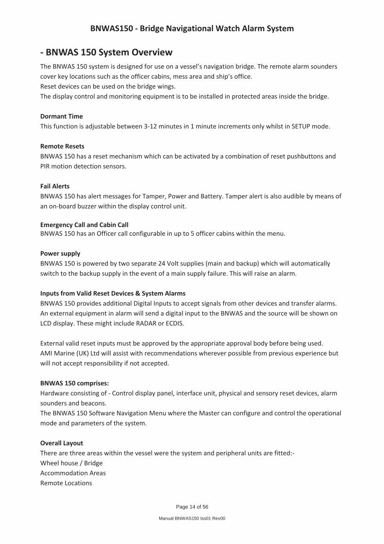
MD-150 Passive Infra-red Detectors Identify set of BNWAS 150 PIR Dimensional and Wiring Details – Drawing (Appendix C). To minimize false detections: In addition, a few important rules must be observed while selecting a mounting location: If two PIR units are installed in the bridge they should not face each other and must be mounted at least 2 metres apart. Do not install the PIR units in places where the detector circuit detects constantly or intermittently, due to environmental interference. Mounting Remove the front cover as shown below.
Cover and PCB Removal
Loosen the vertical adjustment screw, slide the PCB down and remove it via the “keyhole”. Pull the PCB straight out and put it aside until required again. Refer to the following figure and punch out the mounting knockouts at the rear wall of the base (for surface mounting) or at the angled sides of the base (for corner mounting).
Inside View
Punch out any one of the wiring knockouts shown above. Hold the base against the bulkhead at the selected installation location, mark the points for drilling and drill the pilot holes. Pass the wires through the wiring inlets into the base and attach the base to the bulkhead. Return the PCB to its place within the base.

BNWAS150 - Bridge Navigational Watch Alarm System
Page 28 of 56
Manual BNWAS150 Iss01 Rev00
Vertical Adjustment: To maintain maximum coverage range the vertical adjustment scale must be adjusted in accordance with the actual mounting height (refer to below figure). Loosen the vertical adjustment screw and slide the printed circuit board up or down until the pointer shows the actual mounting height on the scale. When done, re-tighten the screw tight.
Vertical Adjustment Setting the LED Jumper
Setting the Pulse Counter: Set the PIR detector for maximum false detection immunity; shift the jumper between to 2 & 3. In this position, three consecutive motion events are required to trip the PIR detector.
Pulse Counter Setting Options
Detection Walk Test Verify that the LED is enabled. Install the front cover in place. Walk across the detector’s field of view in different directions, at various distances from the detector, and verify proper detection throughout the detector's coverage area (the red LED will illuminate for several seconds each time motion is detected). When done, remove the cover and disable the LED to prevent any possible pollution of the officer’s night vision. Remount the cover and fasten it to the base using the small screw at the bottom.

BNWAS150 - Bridge Navigational Watch Alarm System
Page 29 of 56
Manual BNWAS150 Iss01 Rev00
- Equipment Connection The following connection diagrams show how to the assemble and interconnect the BNWAS150 system
Figure 16 - DU-150 Distribution Interface Unit
Please note: Additional terminals for the 0V and cable screens are provided below the ribbon cable socket. These may be used for any 0V or screen connection. DWG 1 - Data Input

BNWAS150 - Bridge Navigational Watch Alarm System
Page 30 of 56
Manual BNWAS150 Iss01 Rev00
DWG 2 - Reset Pushbuttons with Buzzer (Bridge Wing)
DWG 3 - Reset Pushbuttons (Bridge)
DWG 4 - PIR Motion Sensors
BNWAS150 - Bridge Navigational Watch Alarm System
Page 31 of 56
Manual BNWAS150 Iss01 Rev00
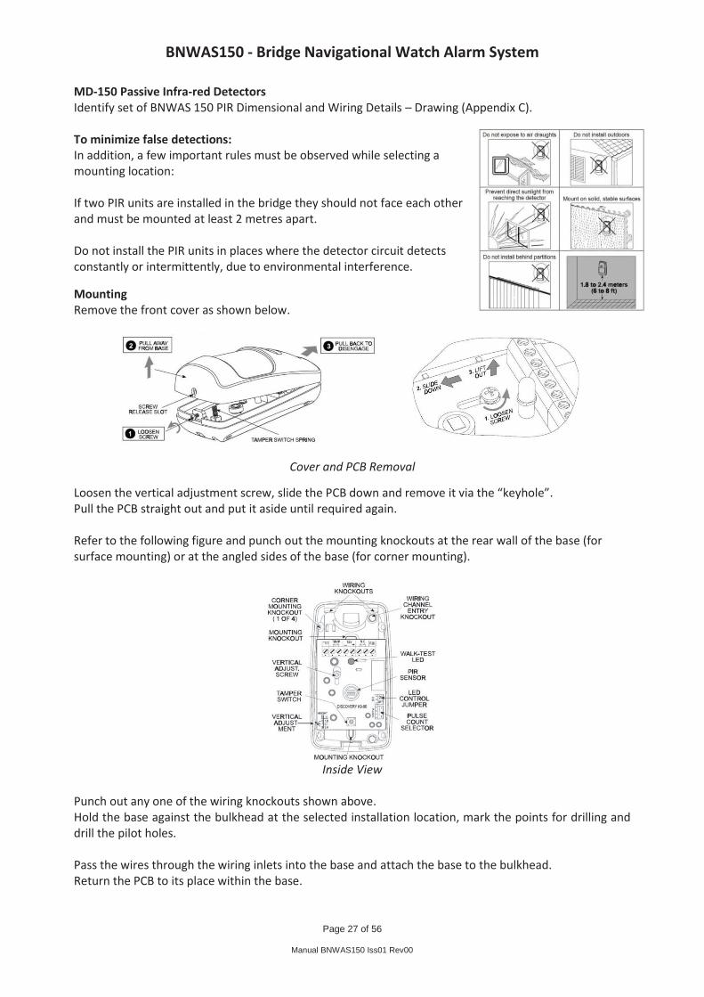
DWG 5 - Power Supply Input
DWG 6 - Unacknowledged Alarm Inputs – Non-specific
DWG 7 - Automatic Activation – Autopilot Input

BNWAS150 - Bridge Navigational Watch Alarm System
Page 32 of 56
Manual BNWAS150 Iss01 Rev00
DWG 8 - Cabin Alarms (See Figure 19 Page 34)
DWG 9 - Sounder Alarms For Stage 1,2 and 3 (See Figure 19 Page 34)
DWG 10 - External System Resets
BNWAS150 - Bridge Navigational Watch Alarm System
Page 33 of 56
Manual BNWAS150 Iss01 Rev00
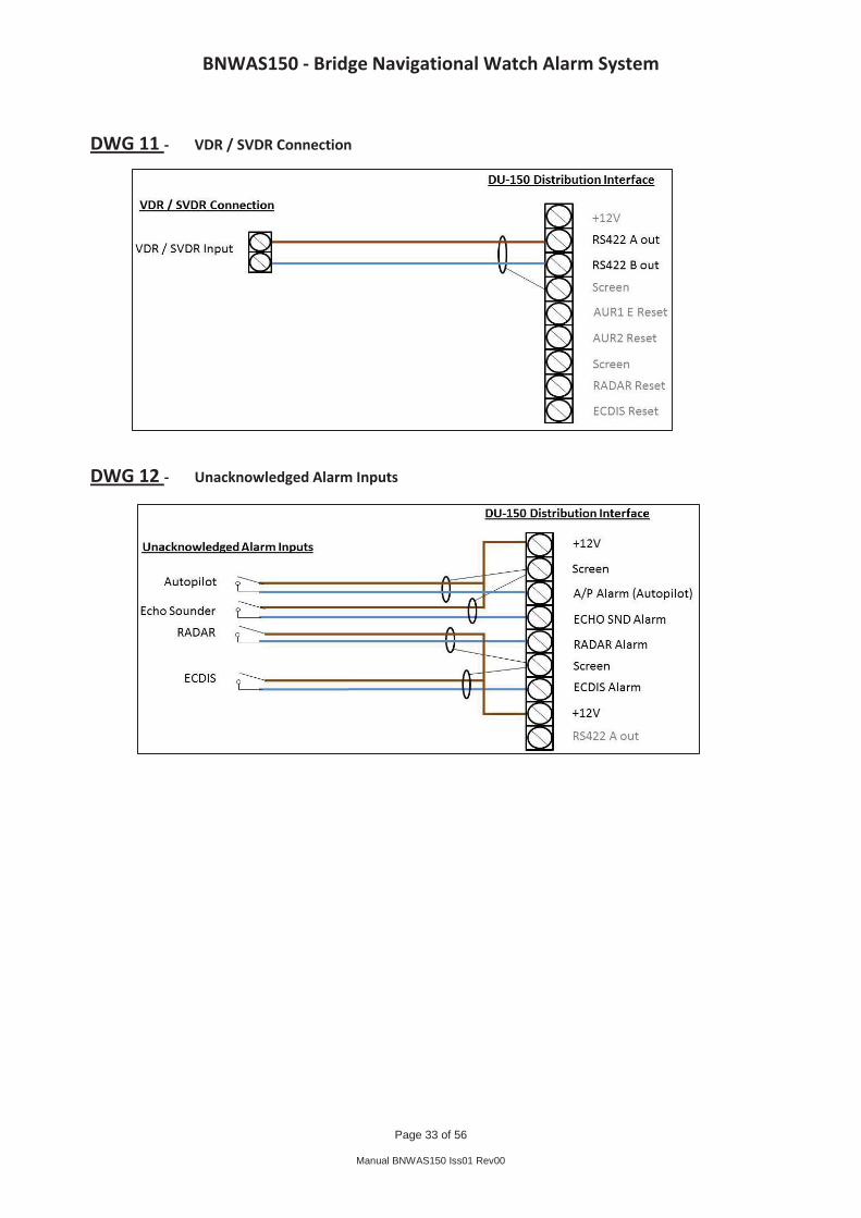
DWG 11 - VDR / SVDR Connection
DWG 12 - Unacknowledged Alarm Inputs

BNWAS150 - Bridge Navigational Watch Alarm System
Page 34 of 56
Manual BNWAS150 Iss01 Rev00
- Equipment Assembly and Internal Connection The below diagrams show the assembly and internal connections of the peripheral equipment
Figure 17 - RI-150 Reset Pushbutton
Figure 18 - RE-150 Reset Pushbutton with Buzzer
Figure 19 - SD-150 Alarm Sounder / SB-150 Sounder Beacon
To DU-150 DWG 2
To DU-150 DWG 3

BNWAS150 - Bridge Navigational Watch Alarm System
Page 35 of 56
Manual BNWAS150 Iss01 Rev00
- Software Setup and Operation
Switching On The BNWAS 150 SETUP Menu The SETUP mode allows the user to access the SETUP MENU and customise the timing parameters within the BNWAS 150 menus. To enter the SETUP mode insert the key and turn clockwise to SETUP. Mode Selection In the SETUP menu you can step sequentially through the three different modes of operation by pressing the SELECT button. The three different modes are:-
ON The system functions as per the set timing parameters. Alarms as per IMO standard MSC128(75).
OFF System operation inhibited. The Emergency Call function is still operational AUTO When this mode is selected the system runs as per “ON” mode only if Autopilot signal is active; otherwise operation is inhibited. This function should only be used with class approval.
STAGE ALARM 3 Timing Selection Press the SELECT button until you arrive at the Stage Alarm 3 timing option.
Stage 2 to Stage 3 Delay Time The Stage 2 to Stage 3 delay is defined in seconds. This is the time from the Stage 2 alarm becoming active to the Stage 3 alarms becoming activate, assuming Stage 2 is not acknowledged in the meantime. The Stage 2 to Stage 3 delay is configured using the UP and DOWN buttons. A time between 90 seconds and 180 seconds in 10 second steps can be entered. When the desired timing is displayed press the SELECT button.
DORMANT Period Timing Selection Press the SELECT button until you arrive at the dormant period timing option.
Dormant Period Time The dormant period is defined in minutes. This period is the time taken from initial start-up, or operator reset, to the Visual Alert Stage being initiated. The dormant period is configured using the UP and DOWN buttons to toggle between digits 3 and 12. When the desired period is displayed press the SELECT button.

BNWAS150 - Bridge Navigational Watch Alarm System
Page 36 of 56
Manual BNWAS150 Iss01 Rev00

BNWAS150 - Bridge Navigational Watch Alarm System
Page 37 of 56
Manual BNWAS150 Iss01 Rev00
BNWAS150 Startup On first power up a message from the system designers will appear on the display. The software version and date will then be displayed followed by CPU 1 and CPU 2 running a self-test, a short beep will be heard on completion. After a few seconds the operating screen will be displayed.
Entering Setup Insert the MODE key and turn clockwise – the status indication will change from RUN to SETUP Press SELECT button - mode will change from ON to OFF The BNWAS is now set to OFF. Pressing the SELECT button again, will cause the mode to change from OFF to Auto OFF If the Autopilot is connected the system will automatically turn ON and OFF as the autopilot is engaged and disengaged.
Designed and built by AMI Marine In Great Britain
ON 03 : 00 SETUP Cabin 1 _ 3 _ _
OFF 03 : 00 SETUP Cabin 1 _ 3 _ _
Auto OFF 03 : 00 SETUP Cabin 1 _ 3 _ _
V 1.00 10/11/11 CPU 1 OK CPU 2 OK
ON 02 : 27 RUN Cabin 1 _ 3 _ _

BNWAS150 - Bridge Navigational Watch Alarm System
Page 38 of 56
Manual BNWAS150 Iss01 Rev00
Mode Selection Pressing the SELECT button again, will change Dormant Period to ON. If the key is now turned to the RUN position and removed, the system is now in the ON mode. Pressing the SELECT button again will change ON to OFF. If the key is turned to RUN and removed the system is now in the OFF mode. Pressing the SELECT button again will change OFF to Auto OFF. If the key is turned to RUN and removed the system is now in the Automatic mode. The display will change to Auto ON if the Autopilot is connected and the Autopilot is engaged.
Stage 2 to Stage 3 Delay
Pressing the SELECT button again will change Auto OFF to Stage Alarm 3. By using the UP and DOWN buttons the stage 3 alarm time can be changed, from 90 seconds (1:30) up to 180 seconds (3:00 minutes) in 10 second steps.
Initial Dormant Period Pressing the SELECT button again will change Stage
Alarm 3 to Dormant Period. By using the UP and DOWN buttons the dormant period time can be changed from 3 minutes to 12 minutes, in 1 minute steps.
Stage Alarm 3 0 1 : 30 SETUP Cabin 1 _ 3 _ _
Dormant Period 03 : 00 SETUP Cabin 1 _ 3 _ _
OFF 03 : 00 SETUP Cabin 1 _ 3 _ _
Auto OFF 03 : 00 SETUP Cabin 1 _ 3 _ _
ON 03 : 00 SETUP Cabin 1 _ 3 _ _

BNWAS150 - Bridge Navigational Watch Alarm System
Page 39 of 56
Manual BNWAS150 Iss01 Rev00
Operational Sequence When the BNWAS countdown reaches 00 : 00 the STAGE ALARM message will appear. The display and the remote reset buttons will now flash. To reset the system press the RESET button or press a remote reset button. 15 Seconds after Stage Alarm is displayed STAGE ALARM 1 will be displayed and the Stage 1 alarm on the display unit will audible alarm along with any local sounder. To reset the system press the RESET button or press a remote reset button. 15 Seconds after Stage Alarm 1 is displayed STAGE ALARM 2 will be displayed and Stage 2 and the selected cabin sounders will also begin to sound. To reset the system press the RESET button or press a remote reset button. 1:30 to 3:00 minutes after stage 2, depending on the stage 3 delay setting, STAGE ALARM 3 will be shown and all sounders will sound in all installed locations. To reset the system press the RESET button on the display. NB: Pressing the remote resets, or motion detected by the PIR will not reset the system once stage 3 alarm has been reached. EMERGENCY CALL, In the event of an emergency press and hold the EMERGENCY CALL button until the alarm sounds. All stage 1 and the selected cabin sounders will become active. To reset the system press the RESET button on the display. NB: Pressing the remote resets or motion detected by the PIR will not reset the EMERGENCY CALL.
ON 00 : 00 STAGE ALARM RUN Cabin 1 _ 3 _ _
ON 00 : 00 STAGE ALARM 1 RUN Cabin 1 _ 3 _ _
ON 00 : 00 STAGE ALARM 2 RUN Cabin 1 _ 3 _ _
ON 00 : 00 STAGE ALARM 3 RUN Cabin 1 _ 3 _ _
ON 0 1 : 27 STAGE ALARM 3 RUN EMERGENCY CALL Cabin 1 _ 3 _ _
BNWAS150 - Bridge Navigational Watch Alarm System
Page 40 of 56
Manual BNWAS150 Iss01 Rev00
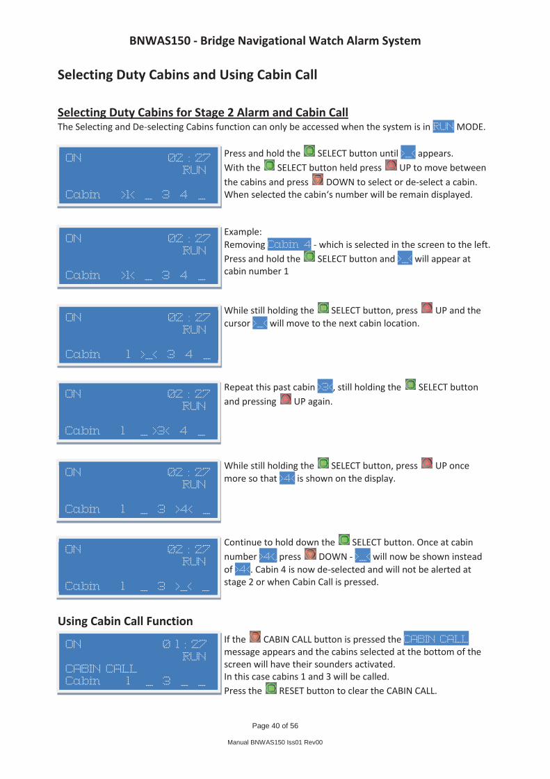
Selecting Duty Cabins and Using Cabin Call Selecting Duty Cabins for Stage 2 Alarm and Cabin Call The Selecting and De-selecting Cabins function can only be accessed when the system is in RUN MODE.
Press and hold the SELECT button until >_< appears. With the SELECT button held press UP to move between the cabins and press DOWN to select or de-select a cabin. When selected the cabin‘s number will be remain displayed. Example: Removing Cabin 4 - which is selected in the screen to the left. Press and hold the SELECT button and >_< will appear at cabin number 1 While still holding the SELECT button, press UP and the cursor >_< will move to the next cabin location. Repeat this past cabin >3<, still holding the SELECT button and pressing UP again. While still holding the SELECT button, press UP once more so that >4< is shown on the display. Continue to hold down the SELECT button. Once at cabin number >4<, press DOWN - >_< will now be shown instead of >4<. Cabin 4 is now de-selected and will not be alerted at stage 2 or when Cabin Call is pressed.
Using Cabin Call Function If the CABIN CALL button is pressed the CABIN CALL message appears and the cabins selected at the bottom of the screen will have their sounders activated. In this case cabins 1 and 3 will be called. Press the RESET button to clear the CABIN CALL.
ON 02 : 27 RUN Cabin >1< _ 3 4 _
ON 02 : 27 RUN Cabin >1< _ 3 4 _
ON 02 : 27 RUN Cabin 1 >_< 3 4 _
ON 02 : 27 RUN Cabin 1 _ >3< 4 _
ON 02 : 27 RUN Cabin 1 _ 3 >4< _
ON 02 : 27 RUN Cabin 1 _ 3 >_< _
ON 0 1 : 27 RUN CABIN CALL Cabin 1 _ 3 _ _

BNWAS150 - Bridge Navigational Watch Alarm System
Page 41 of 56
Manual BNWAS150 Iss01 Rev00
External Reset (if external equipment connected)
RADAR RESET message will be shown when the RADAR is in use by an operator and the BNWAS timer will reset. (This will only be shown if the RADAR in use connection is made) ECDIS RESET message will be shown when the ECDIS is in use by an operator and the BNWAS timer will reset. (This will only be shown if the ECDIS in use connection is made) AUXILIARY 1 RESET message will be shown when the equipment connected to Auxiliary 1 is in use by an operator and the BNWAS timer will reset. (This will only be shown if the Auxiliary 1 connection is made) AUXILIARY 2 RESET message will be shown when the equipment connected to Auxiliary 2 is in use by an operator and the BNWAS timer will reset (This will only be shown if the Auxiliary 2 connection is made)
ON 03 : 00 RUN RADAR RESET Cabin 1 _ 3 _ _
ON 03 : 00 RUN ECDIS RESET Cabin 1 _ 3 _ _
ON 03 : 00 RUN AUXILIARY 1 RESET Cabin 1 _ 3 _ _
ON 03 : 00 RUN AUXILIARY 2 RESET Cabin 1 _ 3 _ _

BNWAS150 - Bridge Navigational Watch Alarm System
Page 42 of 56
Manual BNWAS150 Iss01 Rev00
Unacknowledged Alarms (if external equipment connected)
RADAR ALARM. This will be displayed if an unacknowledged alarm is received from the Radar. Pressing the RESET button will display any other active alarms but will not reset the alarm. (This will only be shown if the RADAR alarm is connected) ECDIS ALARM. This will be displayed if an unacknowledged alarm is received from the ECDIS. Pressing the RESET button will display any other active alarms but will not reset the alarm. (This will only be shown if the ECDIS alarm is connected) AUTOPILOT ALARM. This will be displayed if an unacknowledged alarm is received from the Autopilot. Pressing the RESET button will display any other active alarms but will not reset the alarm. (This will only be shown if the Autopilot alarm is connected) ECHO SOUNDER ALARM. This will be displayed if an unacknowledged alarm is received from the Echo Sounder. Pressing the RESET button will display any other active alarms but will not reset the alarm. (This will only be shown if the Echo Sounder alarm is connected)
UNACKNOWLEDGED ALARM. This will be displayed if any unacknowledged alarms, other than those listed above, are received by the BNWAS. Pressing the RESET button will display any other active alarms but will not reset the alarm.
NOTE!! For all of the above unacknowledged alarms, pressing the RESET button will have not reset any alarm until the equipment generating the alarm has been acknowledged.
ON 00 : 00 STAGE ALARM 2 RUN RADAR ALARM Cabin 1 _ 3 _ _
ON 00 : 00 STAGE ALARM 2 RUN AUTOPILOT ALARM Cabin 1 _ 3 _ _
ON 00 : 00 STAGE ALARM 2 RUN ECHO SOUNDER ALARM Cabin 1 _ 3 _ _
ON 00 : 00 STAGE ALARM 2 RUN UNACKNOWLGED ALARM Cabin 1 _ 3 _ _
ON 00 : 00 STAGE ALARM 2 RUN ECDIS ALARM Cabin 1 _ 3 _ _
BNWAS150 - Bridge Navigational Watch Alarm System
Page 43 of 56
Manual BNWAS150 Iss01 Rev00
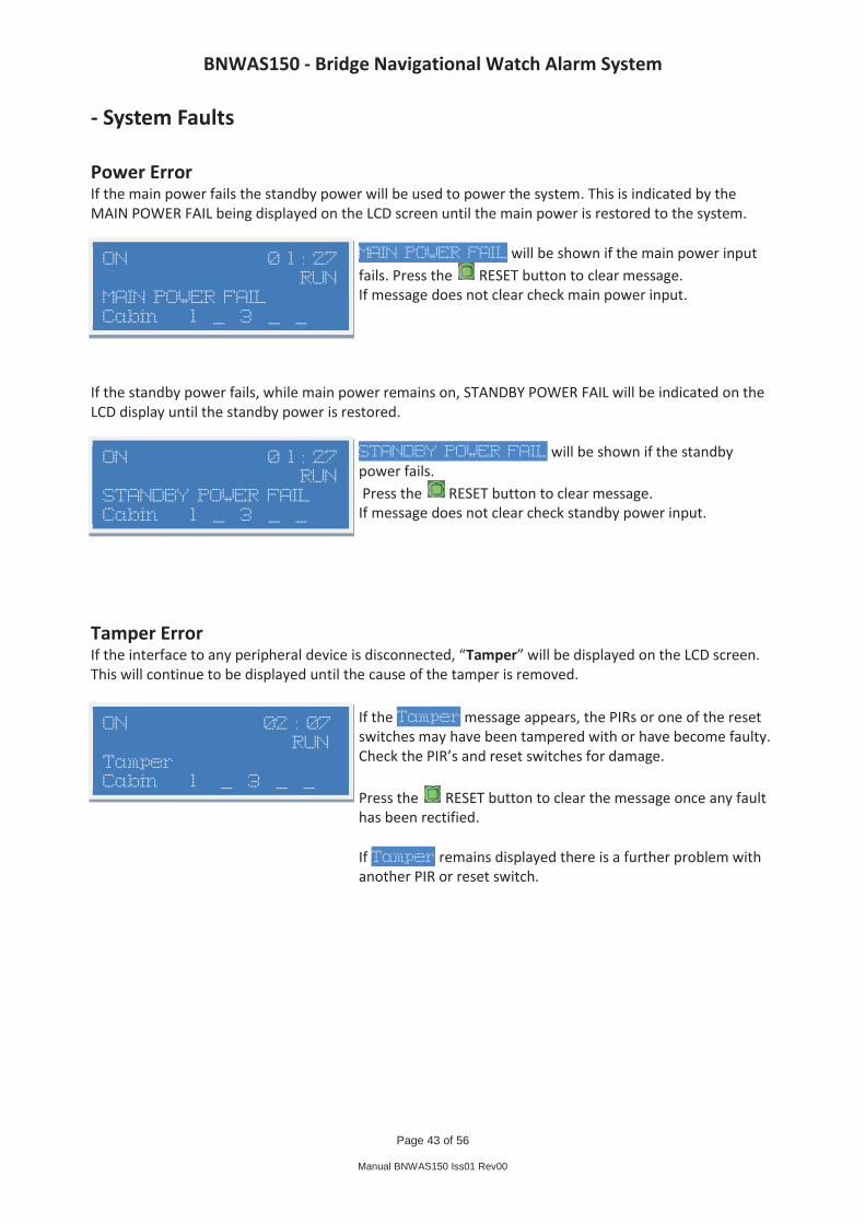
- System Faults Power Error If the main power fails the standby power will be used to power the system. This is indicated by the MAIN POWER FAIL being displayed on the LCD screen until the main power is restored to the system.
MAIN POWER FAIL will be shown if the main power input fails. Press the RESET button to clear message. If message does not clear check main power input.
If the standby power fails, while main power remains on, STANDBY POWER FAIL will be indicated on the LCD display until the standby power is restored.
STANDBY POWER FAIL will be shown if the standby power fails. Press the RESET button to clear message. If message does not clear check standby power input.
Tamper Error If the interface to any peripheral device is disconnected, “Tamper” will be displayed on the LCD screen. This will continue to be displayed until the cause of the tamper is removed.
If the Tamper message appears, the PIRs or one of the reset switches may have been tampered with or have become faulty. Check the PIR’s and reset switches for damage. Press the RESET button to clear the message once any fault has been rectified. If Tamper remains displayed there is a further problem with another PIR or reset switch.
ON 02 : 07 RUN Tamper Cabin 1 _ 3 _ _
ON 0 1 : 27 RUN STANDBY POWER FAIL Cabin 1 _ 3 _ _
ON 0 1 : 27 RUN MAIN POWER FAIL Cabin 1 _ 3 _ _

BNWAS150 - Bridge Navigational Watch Alarm System
Page 44 of 56
Manual BNWAS150 Iss01 Rev00
- Maintenance guide The BNWAS 150 system requires periodic (annually) confirmation that all sensors are active, and conduct a full system integrity check. Any damaged/inactive peripherals MUST be replaced by a suitable spare part by an approved engineer. All cabling and interfaces should be re-checked to confirm system integrity and any damaged cables must be replaced/re-wired if required by an approved engineer. Any changes made above must be tested to confirm system operation. Any warranty void marks/visible tampering must be logged to prevent future disruption and system damage.

BNWAS150 - Bridge Navigational Watch Alarm System
Page 45 of 56
Manual BNWAS150 Iss01 Rev00
- Commissioning Checklist
AMI Marine (UK) Ltd Southampton
Vessel Hull No/Name: IMO Number: Flag State: BNWAS-150
Bridge Navigational Watch Alarm System COMMISSIONING & INSTALLATION REPORT
Class Society: Serial No: Install Date: Commissioning Engineer:
01. Pre-Requisites
This commissioning checklist and report must be carried out upon completion of the installation of the BNWAS 150 system:
Installation manual available for reference.
All peripheral equipment’s that are to be connected are operational.
Make any necessary crew announcements warning of BNWAS testing.
02. Test Equipment
The following equipment is recommended for an effective and complete install.
Digital Multimeter
Laptop with serial cable and HyperTerminal or similar
03. Visual Inspection Check Requirement Observation
Check all equipment fixings are secure.
All equipment are fixed to the vessel securely and not liable
Check all units for physical condition.
There is no physical damage to the exterior of any of the equipment.
Check all inter-unit cabling and the external equipment cable route.
The cables are secured in or to a proper cable support.
Check cable entry into the BNWAS equipment.
The cables must enter the BNWAS equipment through a suitable sized gland and not be able to move.

BNWAS150 - Bridge Navigational Watch Alarm System
Page 46 of 56
Manual BNWAS150 Iss01 Rev00
This page Intentionally Blank

BNWAS150 - Bridge Navigational Watch Alarm System
Page 47 of 56
Manual BNWAS150 Iss01 Rev00
04. Power Supply Electrical Conformance Requirement Observation
24V DC supplies Ensure the supply voltage is of the correct rating.
Main supply voltage rating is correct. Standby supply voltage rating is correct.
Apply the Main and Standby supplies to the BNWAS 150 unit and ensure correct operation.
Ensure the BNWAS DC-150 display powers up. The LCD illuminates and the HMI starts the software initialisation.
Isolate Main supply from the BNWAS 150 and ensure automatic switchover to Backup supply occurs.
Check the BNWAS 150 system continues operation without interruption and that the MAIN POWER FAIL is displayed.
Re-apply Main supply to the BNWAS 150 unit and ensure it automatically switches back over to Main supply.
BNWAS 150 system continues operation without interruption After pressing the RESET button the MAIN POWER FAIL no longer appears.
Isolate Standby supply from the BNWAS 150.
Check the BNWAS 150 system continues operation without interruption and that STANDBY POWER FAIL is displayed.
Re-apply the Standby supply to the BNWAS 150 unit.
BNWAS 150 system continues operation without interruption After pressing the RESET button the STANDBY POWER FAIL no longer appears.

BNWAS150 - Bridge Navigational Watch Alarm System
Page 48 of 56
Manual BNWAS150 Iss01 Rev00
This page Intentionally Blank

BNWAS150 - Bridge Navigational Watch Alarm System
Page 49 of 56
Manual BNWAS150 Iss01 Rev00
05. System Test Conformance Requirement Observation
Check that both the stage 2 to stage 3 alarm and dormant period timings are set as required. All cabins are selected for Stage 2 alarm. If fitted cover the MD-150 PIR
Stage 2 to Stage 3 Delay. (90-180 seconds). Dormant Period. (3-12 minutes) All 5 cabin numbers show on the BNWAS DC-150. To prevent premature reset.
Ensure the system mode is set to ON. Turn the key switch to RUN.
Ensure the BNWAS DC-150 displays ON and RUN. The display starts the countdown from the set dormant period. The RI-150 and RE-150 switch illuminates.
Visual Alarm. The DC-150 has counted down to 00:00 minutes.
Check the BNWAS DC-150 Display Control unit displays STAGE ALARM and the RI-150 Reset unit will flash. Note! That the RE-150 unit will flash and sound alternatively.
Stage 1 Alarm. 15 seconds after 00:00
Check the BNWAS DC-150 Display Control unit displays STAGE ALARM 1 and sounds. If fitted the BNWAS SD-150 sounder also sounds.
Stage 2 Alarm. 30 seconds after 00:00
Check the BNWAS DC-150 displays STAGE ALARM 2. Check that all SD-150 or SB-150 units fitted as Stage 2 alarms also become active and sound.
Stage 3 Alarm. 30 seconds plus Stage2 to Stage3 delay time.
Check the BNWAS DC-150 displays STAGE ALARM 3. Check that all SD-150 or SB-150 units fitted as Stage 3 alarms also become active and sound.
Press the RESET button on the BNWAS DC-150 unit.
BNWAS 150 system resets and the dormant period reverts back to the pre-set time.

BNWAS150 - Bridge Navigational Watch Alarm System
Page 50 of 56
Manual BNWAS150 Iss01 Rev00
This page Intentionally Blank

BNWAS150 - Bridge Navigational Watch Alarm System
Page 51 of 56
Manual BNWAS150 Iss01 Rev00
06. External Inputs (Resets & Unacknowledged Alarms) Conformance Requirement Observation
Verify the external reset functionality. Remove the cover of the PIR.
Verify the MD-150 PIR detects movement and resets the dormant period. Verify the external equipment resets the dormant period.
Cover the PIR. Verify the dormant period
does not reset.
Apply a bridge across the relevant reset input & +12V.
Verify the dormant period resets.
Remove the bridge across the relevant input and the +12V.
Verify the countdown restarts.
Verify the Unacknowledged Alarm Transfer functionality.
Verify the BNWAS DC-150 Display Control unit displays the relevant ALARM and passes it through to Stage 2.
Apply a bridge across the relevant alarm input& +12V.
Verify the Display shows the alarm source & goes to Alarm Stage 2.
Remove the bridge across the relevant input and the +12V. Press the RESET button.
Verify the alarm stops and the display reverts back to normal operation.
07. System Modes Conformance Requirement Observation
Verify the AUTO mode functionality. In the SEUP menu select the AUTO OFF and return the key to RUN position.
Verify the Auto OFF remains displayed on the DC-150 and the time remains static.
If connected apply the Autopilot signal to the BNWAS system. Else apply a bridge across to AUTO I/P and +12V input. J5-12 and 13.
Verify the Auto ON is now displayed on the DC-150 and the time is now counting down.
Remove the Autopilot signal to the BNWAS system. Else remove the bridge across the AUTO I/P and +12V input. J5-12 and 13.
Verify the Auto OFF is now displayed on the DC-150 and the time is again static.
Verify the OFF mode functionality. In the SEUP menu select the OFF and return the key to RUN position.
Verify the that no alarms are active and the system timer remains static.

BNWAS150 - Bridge Navigational Watch Alarm System
Page 52 of 56
Manual BNWAS150 Iss01 Rev00
This page Intentionally Blank

BNWAS150 - Bridge Navigational Watch Alarm System
Page 53 of 56
Manual BNWAS150 Iss01 Rev00
08. Emergency and Cabin Call Conformance Requirement Observation
Verify the Emergency Call functionality. Ensure the Mode is ON and the key to RUN position. Press the Emergency Call.
Verify the system alarms at the ALARM STAGE 3.
Press the RESET button on the BNWAS DC-150 unit.
BNWAS 150 system resets and the dormant period reverts back to the pre-set time.
Verify the Cabin Call functionality. Ensure the Mode is ON and the key to RUN position. Press the Cabin Call.
Verify each of the cabins fitted with a SD-150 or SB-150 is active and sounding.
Press the RESET button on the BNWAS DC-150 unit.
BNWAS 150 system resets the sounders.
09. VDR/S-VDR Output Conformance Requirement Observation
Identify the NMEA0183 data output
No Corrupt data or incorrect values.
10. Signature Page
Type Approval Certificate Issued by Approval Certificate Number
Engineer Authorised by the Manufacturer Ship’s Captain
Initials & Name Initials & Name
Ship’s Stamp
Signature Signature
Date
Original – Retained by vessel. Copy 1 – Retained by Installation Engineer. Copy 2 – Forwarded to AMI Marine (UK) Ltd.

BNWAS150 - Bridge Navigational Watch Alarm System
Page 54 of 56
Manual BNWAS150 Iss01 Rev00
This page Intentionally Blank

BNWAS150 - Bridge Navigational Watch Alarm System
Page 55 of 56
Manual BNWAS150 Iss01 Rev00
- Warranty Card AMI Marine (UK) Warranty; (abbreviated, full version on request) The Warranty Period is 24 months – first 12 months covers parts and labour, the second 12 months covers parts only - from date of dispatch unless an alternative period has been otherwise agreed in writing. This warranty shall only apply where the REGISTRATION CARD (below) and COMMISSIONING REPORT (above) have been properly completed and returned to AMI Marine (UK) Ltd within the period of 21 days from installation. Returns Procedure; Send an email requesting an official Returns Authorisation Number via email with the subject “REQUEST FOR RETURN AUTHORISATION” to [email protected] Please do not send any equipment to AMI Marine (UK) Ltd without an official Return Authorisation Number. Documents to be included; A copy of the original INSTALLATION REPORT and a print out of your RETURN MATERIAL AUTHORISATION INFORMATION EMAIL, and enclose both in the return package. Please ensure the returned equipment is packaged safely and securely and according to carrier instructions. Damage incurred during return shipping due to inadequate protection will render the item ineligible for return, repair, or exchange under the Warranty Terms. Items not received by AMI Marine (UK) Ltd, will not be credited. Most authorised returns should be returned to the address below - however there are some exceptions, so DO NOT ship to this address without first reviewing your RETURN AUTHORISATION INFORMATION EMAIL for applicable return instructions: AMI Marine (UK) Ltd Unit 2 Tower Industrial Estate Tower Lane Eastleigh Hants SO50 6NZ UK A full explanation of AMI Marine (UK) Ltd warranty conditions can be found on our web site or requested via email. * Terms of Service and Policies are subject to change without notice.
------------------------------------------------------------------------------------------------------------------------------------------------------------------------------------------
Please complete and return to AMI Marine (UK) either by post to the above address or by email to [email protected]
Warranty Registration Form
Model Number
Serial Number
Date of Install
Installation Company
Vessel Name
IMO Number