bridges - freenguyen.hong.hai.free.fr/ebooks/science and engineering/engin… · 20.3.3 more...
TRANSCRIPT
This page has been reformatted by Knovel to provide easier navigation.
20 Bridges
D J Lee BScTech, DIC, FEng, FICE,FIStructE
B Richmond BSc(Eng), PhD, FCGI, FICEMaunsell Group
Contents
20.1 Plan of work 20/3
20.2 Economics and choice of structural system 20/3
20.3 Characteristics of bridge structures 20/1720.3.1 Theory of suspension bridges and arch
bridges 20/1720.3.2 Bridge girders of open section 20/2120.3.3 More general behaviour of suspension
bridges and arches 20/2220.3.4 Single-cell box girder 20/2420.3.5 Boxes with discrete diaphragms 20/2520.3.6 Box beams with continuous
diaphragms 20/2620.3.7 Box girders with cantilevers 20/2720.3.8 Multiple web girders of open cross-
section 20/2720.3.9 Multiple single-cell box beams 20/2920.3.10 Multicellular bridge decks 20/3120.3.11 Symmetrical loading 20/3120.3.12 Antisymmetrical loading 20/3120.3.13 Design curves 20/32
20.4 Stress concentrations 20/3320.4.1 Shear lag due to concentrated loads 20/3320.4.2 Changes in thickness and cut-outs 20/33
20.5 Concrete deck slabs 20/34
20.6 Skew and curved bridges 20/3520.6.1 Skew 20/3520.6.2 Curved in plan 20/35
20.7 Dynamic response 20/36
20.8 Appendix: Movable bridges 20/38
20.9 Items requiring special consideration 20/38
References 20/40
Bibliography 20/41

20.1 Plan of work
The design of bridges requires the collection of extensive dataand from this the selection of possible options. From such areview the choice is narrowed down to a shortlist of potentialbridge designs. A sensible work plan should be devised for themarshalling and deployment of information throughout theproject from conception to completion. Such a checklist willvary from project to project but a typical example might bedrawn up on the following lines.
1I) Feasibility phase:
(a) data collection;(b) topographical and hydrographical surveys;(c) hydrological information;(d) geological and geotechnical information;(e) site investigation requirements for soil and rock evaluation;(f) Meteorological and aerodynamic data;(g) assembly of basic criteria;(h) likely budget.
(2) Assembly of design criteria'.
(a) data and properties on the material to be used includingsteel, concrete, aluminium, timber, masonry, etc.;
(b) foundation considerations;(c) hydraulic considerations, flood, scour;(d) loading and design criteria;(e) clearances height and width (such as for navigation, traffic);(f) criteria for gradients, alignment, etc.;(g) hazards such as impact, accident;(h) proximity to other engineering works, etc.;(i) functional requirements;(j) transportation and traffic planning;(k) highway and/or railway engineering aspects;(I) drainage requirements;(m) provision for services (water, sewage, power, electricity,
telephone, gas, communications links, etc.);(n) design life and durability considerations.
(3) Design phase:
(a) choice of bridge;(b) detailed design of bridge including foundations, substruc-
ture and superstructure;(c) production of drawings and documentation, etc.;(d) preparation of quality assurance plan;(e) estimation of cost and programme.
(4) Construction phase:
(a) contractual matters;(b) construction methods;(c) budget and financial control;(d) quality control;(e) supervision of construction;(f) commissioning;(g) operating, inspection and maintenance schedules for each
part of the work.
(5) Performance phase:
(a) obligations of owner;(b) management of facility;(c) inspection, maintenance and repair;(d) rehabilitation and refurbishment requirements (change of
loading, widening, change of use and durability aspects);(e) decommissioning and demolition.
Such a project list serves to highlight the various and sometimesconflicting requirements of a bridge project, and those aspects
where the bridge designer should seek the approval of the clientthroughout all the stages of a project for a truly successfulcollaboration.
This chapter covers the selection and analysis of bridgesuperstructures and attempts to relate the most frequently usedbridging materials - steel and concrete.
As extensive treatment as possible is given to box girderanalysis, an important aspect of modern bridge construction.Information about individual bridges will be found in thebibliography. Reference to these specific examples will assist anunderstanding of the historical background and the existingstate of the art. A good general review of the structural form ofbridges is given by Beckett,' whilst a sensitive aesthetic assess-ment is provided by Mock.2
Masonry arches and steel trusses have not been dealt with butinteresting examples of these types of bridges are contained inthe reference list.
The principles developed in this chapter for open or closedsections are applicable to trussed structures if suitable modifica-tions are made to allow for shear behaviour of the truss system.
Thus, the authors hope that there is adequate information inthis chapter to make preliminary assessments for most modernbridge designs by methods which enable the essential natures ofstructural behaviours to be perceived and which can be de-veloped to detailed analyses without the necessity of revisingbasic principles.
20.2 Economics and choice ofstructural system
Cost comparisons which would make it possible to arrive at themost economical choice of material, structural form, span, etc.have been sought for many years by bridge engineers, but sincethe costs of any one bridge depend on the circumstancesprevailing at that time, the information is always imprecise.Cost data must be up to date and sufficiently detailed to allowadjustments to be made for changed circumstances. It is thechanges in these factors which lead to new methods of construc-tion and new structural systems; a major change of this kind hasbeen that involving box girders, plate girders and trusses.
A very early steel box girder bridge, the Britannia Bridge,3
built by Stephenson over the Menai Straits (main spans 14Om,completed in 1850) was very successful and was in regular usefor railway trains until it was damaged by fire. Each span waslifted into place in its entirety by hydraulic jacks. The advan-tages of truss construction were, however, sufficient to convinceengineers for the next 100 years that box structures were noteconomical, though plated structures were used in the form of I-beams for smaller spans and lighter loads. The steel box girderre-emerged as a structural system for bridges after the SecondWorld War, although short-span multicellular bridges in rein-forced concrete had been used for short spans in the 1930s. In1965 a large proportion of structures other than short spanswere built as box structures of one form or another. A greaterdegree of selectivity then began to emerge and open cross-sections, even for substantial spans, were again being usedprovided no problems of aerodynamic stability arose. The use ofplate girders has been further encouraged by the reaction causedby failures of steel box girder bridges but it seems likely that abalanced view of the merits of various forms of construction willprevail.
Figure 20.14 shows the possible cross-sections for bridgestructures which can include truss systems if the plane of eachtriangulated panel is represented by either a web or flangemember. The significance of box structures in a more generalsense now becomes clear. It is the open cross-section that is aparticular, although important, form of construction, whereas

the box system is perhaps a misleadingly simple description ofthe general range of structures.
The most basic structural dimension for a given span affect-ing both the least-cost and the least-weight methods of measur-ing efficiency is the effective lever arm of the structure forresisting bending moments resulting from the vertically actingforces from self-weight and imposed loads and vertical compo-nents of the support reactions. In bridges which depend onhorizontal reactions from the ground, this distance is the rise ofan arch above its foundations, or the dip of a suspension cablebetween towers. If the supports are at different levels, the dip orrise is measured vertically from the chord joining the supports.
The high strength: weight ratio of steel wire and favourableprice:strength ratio results in dip:span ratios of 0.1 beingsuitable for even the longest suspension bridges (Table 20.1).The shallow cable has a higher tension which improves itscapacity for carrying uneven loads without large deflection andincreases its natural frequency of vibration. The cost of the cablealone is not, however, sufficient to reach conclusions on eco-nomics, since the cost of foundations to anchor the cables issubstantial and varies with the ground conditions.
The lower strength-.weight ratios of steel in compression andconcrete combined with the destabilizing effect of the compres-sive force of the thrust lead to the rise:span ratios beingconsiderably higher on average (Tables 20.3 and 20.4). Goodfoundations and the requirements of local topography may leadto reduced ratios, and arches - such as at Gladesville,5 which arein flat country and yet have the roadway running above the archrib - and the requirement for a low rise to minimize the cost ofapproach embankments.
The depth between compression and tension flanges is thelever arm of a simply supported beam structure, such as a truss,plate girder or box girder. If the structure is continuous at bothends, the sum of the depths at the centre span and one of thesupports is the lever arm (Tables 20.6 and 20.7).
Name oj bridge Year
Humber 1981VerrazanoNarrows 1964
Golden Gate 1937Mackinac Straits 1957Minami Bisan-Seto (Road/Rail) u.c.
(1988)
2nd Bosphorus 1988Bosphorus 1973GeorgeWashington 1932
Tagus 1966Forth 1964Kita Bisan-Seto(Road/Rail) u.c.
(1988)
Severn 1966OhnarutoTacoma NarrowsII 1950
Lions Gate 1938
Mainspan(m)
1410
1298
12801158
1100
10901074
1067
10131006
990
988876
853
846
Cablesag(m)
125
117
145108
93.4
96
10691
82
87
Span/sag
11.3
11.0
8.810.76
11.5
11.1
9.511.0
12.0
9.8
Location
Humber River
New YorkHarborSan FranciscoMichigan
Inland Sea ofJapan
Ortakoy, Turkey
Hudson River,New York stateLisbonQueensferry
Inland Sea ofJapanBeachley, UKNaruto, Japan
Puget Sound,WashingtonVancouver
u.c. = under construction
Table 20.1 The world's leading suspension bridges
Number of webs in each boxFigure 20.1 Classification of bridge-deck classifications. (After Lee (1971) The selection of box-beam arrangements in bridge design',Developments in bridge design and construction. (Crosby Lockwood).
orthotropic plates
multiple web(M-1)
multiple box(M-2)
quadruple web(Q-1)
quadruple box(Q-2)
quadruple triple(Q-3)
triple web(T-1)
triple box(T-2)
triple-triple(T-3)
double web(D-1)
double box(D-2)
double triple(D-3)
single web(S-D
single box(S-2)
single triple(S-3)
single-quadruple(S-4)
multicellular(S-M)
voided slab
MMultiple
QQuadruple
TTriple
DDouble
SSingle
(M-3) etc

Table 20.2 Leading cable-stayed bridges
Name
AnnacisHooghlyBarrios de Luna
Hitsuishijima
Saint Nazaire
St Johns River
RandeLuling
Dusseldorf Flehe
Tjorn
Sunshine SkywayYamatogawaDuisberg-Neuenkamp
JindoWestgate
Brazo Largo
Zarate
Posadas-Encarnacion
Kohlbrand
Knie
Brotonne
Bratislava
ErskineSeverinsDnieperPasco KennewickNeiwied
Deggenau
Coatzacoalcos IIKurt Schuhmacher
Location
Vancouver, CanadaCalcutta, IndiaSierra Cantabrica,
SpainIwakurojima (two
bridges)
Year
1986u.c.
W
(u.c.
Loire estuary, Brittany 1974France
Jacksonville, Florida,US
Vigo Estuary, SpainMississippi River,
Louisiana, USW. Germany
Askerofjord, Sweden
Florida, USOsaka, JapanRhine River,
Duisberg-Moers,W. Germany
S. KoreaYarra River,
Melbourne,Australia
Guagu, Argentina
Palmas, Argentina
Paraguay, Argentina
Hamburg, W.Germany
Rhine River,Dusseldorf,W. Germany
Seine River, Rouen,France
Danube River,Czechoslovakia
Clyde River, ScotlandCologne, W. GermanyKiev, Soviet UnionWashington State, USRhine River,
W. Germany
Danube River, W.Germany
MexicoRhine River,
Mannheim Nord,W. Germany
19781982
1979
1981
1987
1970
19851978
1977
1977
1974
1969
1977
1971
1971195919761978
1975
19841971
Main span Span Cables Material Functionlength (m) arrange-
mentPlanes Arrangement
465457
4401987)420
404
400
400372
368
366
366355350
345336
330
330
330
325
320
320
316
305302300299292
290
288287
SymSym
SymSym
Sym
SymSym
Ass
Sym
SymSym
SymSym
Sym
Sym
Sym
Ass
Sym
Ass
SymAssAssSymAss
Ass
SymAss
22
22
2
22
1
2
I11
21
2
2
2
2
1
1
12221
1
12
MFF
FMF
F
F
FF
H sidespan,
MF mainspan
MF
HMF
FDF
F
F
MF
H
MF
S sidespan, Fmainspan
SFMFFMF
F
MFF
St/CSt/C
CSt
St
C
StSt
St/C
St/C
CStSt
StSt/C
St
St
C
St
St
C
St
StStSt/CCSt
St
CSt
Road
RoadRoad and
RailRoad
RoadRoad
Road
Road
RoadRoadRoad
RoadRoad
Road andRail
Road andRail
Road andRail
Road
Road
Road
RoadRoadRoadRoadRoad
Road
RoadRoad and
tram-way
Special notes
Part of Kojma-Sokaido
Multiple side spananchor piers
Replaced steel archdemolished by shipcollision
Connected by longembankment
Multiple side spananchor piers
Two unequal spans,backward leaningtower
Two unequal spans
Two unequal spanswith longitudinalA frame tower
Two unequal spans
Two side spananchor piers

Table 20.2 (cont)
Name
Wadi-el-Kuf
Lever kusen
Friedrich-Ebert
DolsanSpeyer
East HuntingdonTielTheodor Heuss
Oberkassel
ReesSavePapineauSuchiroManuel Belgrano
KessockGeneral Rafael
UrdanetaWyePenang CrossingLuangwaRokko IslandDouble-deckedHawkshaw
Toyosato
Onomichi
Polcevera Creek
Albert CanalBatman
Arno
StromsundAdhamiyah
New Galecopper
Maxau
Ganter
Location
Beida, Libya,N. Africa
Rhine River,W. Germany
Rhine River, BonnNord, W. Germany
S. KoreaRhine River,
W. Germany
Ohio River, USWaal River, HollandDusseldorf,
W. GermanyDusseldorf,
W. GermanyW. GermanyBelgrade, YugoslaviaMontreal, CanadaTokushima, JapanParana River,
Corrientes,Argentina
Inverness, ScotlandLake Maracaibo,
VenezuelaBeachley, WalesMalaysiaZambiaKobe, Japan
New Brunswick,Canada
Yodo River, Osaka,Japan
Hiroshima Pref.,Japan
Genoa, Italy
Godsheide, BelgiumTamar River,
Tasmania
Florence, Italy
SwedenBaghdad, Iraq
Rhine Canal,Amsterdam,Holland
Rhine River,W. Germany
Simplon Pass, Valais,Switzerland
Year
1971
1965
1967
u.c.1975
u.c.19721958
1976
19671978196919761972
19821962
19661980
1977
1969
1970
1968
1967
19771968
1977
19551984
1971
1967
1980
Main spanlength (m)
282
281
280
280275
274267260
258
255254251250245
240235
235225223220
217
216
215
210
210206
206
183182
180
175
174
Spanarrange-ment
Sym
Sym
Sym
SymAss
AssSymSym
Ass
SymSymSymSymSym
SymSym
SymSym
Sym
Sym
Sym
Sym
SymAss
Sym
SymAss
Sym
Ass
Sym
Planes
2
1
1
21
222
1
22112
22
12
2
1
2
2
22
2
21
1
1
2
Cables Material Function Special notes
Arrangement
S
H
MF
FS side
span,F main
spanMFFH
H
HMFFMFF
HS
SH
MF
MF
F
S
MFS side
span,F main
spanS side
span,F main
spanDFH
S
MF
S
C
St
St
StSt
CCSt
St
StStStStC
StC
StC
St
St
St
C
StSt
St/CSt/C
St
St
C
Road
Road
Road
Road
RoadRoadRoad
Road andstreetcar
RoadRailwayRoad
Road
RoadRoad
RoadRoad
Road
Road
Road
Road
RoadRoad
Road
RoadRoad
Road
Road
Road
Articulated
Two unequal spans
Multiple side-spananchor piers
Articulated
Multiple spans.Articulated
Multiple spans.Articulated
Two unequal spans.Forward leaningtower
Towers leanbackwards
Two side-spananchor piers
Twin bridges skewspans
Two unequal spans
Cables enclosed inweb extensions.Curved side spans

Table 20.2 (cont)
Name
North Elbe
DaikokuMassenaSteyregger DonauKamatsugawaIshikara-KakoArakawaGeorge Street
Sancho el Major
Metten
Magliana
DnieperMayaLudwigshafen
Sitka HarbourDanube CanalSecond Main Bridge
Tarano
Harm senBridge of the Isles
St FlorentJulicherstrasse
Location
Hamburg,W. Germany
Yokohama, JapanParis, FranceLinz, AustriaJapanHokkaido, JapanTokyo, JapanRiver Usk, Newport,
WalesRio Ebro, Castejon,
SpainDanube River,
W. GermanyTiber River, Rome,
Italy
Kiev, Soviet UnionKobe, JapanW. Germany
Alaska, USVienna, AustriaFrankfurt,
W. Germany
Alba, Italy
Rotterdam, HollandMontreal, Canada
River Loire, FranceDusseldorf,
W. Germany
Year
1962
1974197119791971197519701964
1967
196419661968
197219751972
1983
19681967
19691963
Main span Span Cables Material Functionlength (m) arrange-
mentPlanes Arrangement
172
165162161160160160152
146
145
145
144139138
137119148
114
108105
10499
Sym
AssSymAssSymSymSymSym
Ass
SymAssEq
SymSymAss
Ass
Eq
EqSym
1
2121212
1
2
212
222
1
2
21
ST
MFMFSHFHH
MF
S
S
FMFF
SSH
S sidespan,
F mainspan
S
FS
St
StStSt/CStStStSt/C
C
C
C
CStSt
St/CCC
St
St/C
St/CSt
Road
RoadRoad
RoadRoadRoad
Road
Road
Road
Road
Road andrail
Road
Road andrail
Road
Special notes
Two unequal spans
Curved in plan. Twounequal spans.Backward leaningtowers
Two unequal spansFour-leg A-frame
tower
Articulated mainspan connects tofin back. Threeanchored sidespans
Two unequal spans.Backward slopingtowers
Ass - asymmetric; C - concrete; DF - double fan; Eq - two equal; F - multiple fan; H - harp; MF - modified fan; S - single; St - steel;ST - star; St/C - composite steel and concrete; Sym - symmetric; u.c. - under construction

Table 20.3 The world's leading steel arch bridges
Name of bridge Span Rise Rise(m) (m) span Year Location
River Gorge 518 1977 West Virginia,US
Bayonne 504 81 0.161 1931 New York, NewYork, US
Sydney Harbour 503 107 0.212 1932 Sydney, AustraliaFremont* 383 u.c. Portland,
Oregon, USPort Mann* 366 76 0.208 1964 Vancouver,
CanadaThatcherf 344 1962 Balboa, PanamaLaviolettef 335 1967 Trois Rivieres,
CanadaZd'akov 330 42.5 0.129 1967 Lake Orlik,
CzechoslovakiaRuncorn-Widnes 330 66.4 0.202 1961 Mersey River,
EnglandBirchenough 329 65.8 0.200 1935 Sabi River,
RhodesiaGlen Canyon 313 1959 Arizona, USLewiston-Queenston 305 48.4 0.159 1962 Niagara River,
N. AmericaHell Gate 298 1917 New York, New
York, USOther steel arch bridges of interest
Rainbow 289 45.7 0.158 1941 Niagara Falls, N.America
Fehmarnsund* 249 43.6 0.175 1963 Fehmarnsund,W. Germany
Adomi (Volta) 245 57.4 0.234 1957 Adomi, GhanaKaiserlei* 220 1964 Frankfurt-am-
Main,W. Germany
u.c. = under construction*Tied arch tCantilever arch
Table 20.4 The world's leading concrete arch bridges
Name of bridge Span Rise Rise(m) (m) span Year Location
Krk II 390 1980 Adria,Yugoslavia
Gladesville 305 40.8 0.134 1964 Sydney, AustraliaRio Parana 290 53.0 0.183 1965 Parana River,
Brazil-ParaguayBloukrans 272 1983 Cape Province,
South AfricaArrabida 270 51.9 0.192 1963 PortugalSando 264 40.0 0.151 1943 Angerman River,
SwedenShibenik 246 1967 Krka River,
YugoslaviaFiumarella 231 66.1 0.286 1961 Catanzaro, ItalyNovi Sad 211 1961 Danube River,
YugoslaviaLinenau 210 1967 Bregenz, AustriaVan Stadens 200 1971 Van Stadens
Gorge, S. AfricaEsIa 192 1942 EsIa River, SpainGroot River 189 1983 Cape Province,
South Africa
RiodasAntas 180 28.0 0.156 1953 BrazilTraneberg 178 26.2 0.147 1934 Stockholm,
SwedenPlougastel
(Albert Louppe) 173 33 0.190 1930 Elorn River,France
Selah Creek 168 1971 Yakima,Washington, US
Bobbejaans 165 1983 Cape Province,South Africa
La Roche-Guyonl61 23.0 0.143 1934 FranceCowlitz RiverBridge 158 Mossyrock,
Washington, USCaracas-
La Guaira 152 39.0 0.257 1952 Caracas,Venezuela
Puddefjord 145 1956 NorwayPodolska 145 1942 Czechoslovakia
Other concrete arch bridges of interest
Revin-Orzy 120 10.0 0.083 Meuse River,France
Glemstal 114 27.1 0.238 Stuttgart,W. Germany
Slangsboda 111 12.0 0.108 1961 Stockholm,Sweden
u.c. = under construction
Table 20.5 The world's leading truss bridges
Name of bridge Span (m) Year Location
Quebec Railway 549 1918 Quebec, CanadaForth Railway 2 x 5 2 1 1890 Queensferry, ScotlandMinato 510 1974 JapanDelaware River 501 Chester, Penn-Bridgeport,
New Jersey, USGreater New
Orleans 480 1958 New Orleans, Louisiana, USHowrah 457 1943 Calcutta, IndiaTransbay 427 1936 San Francisco, California,
USBaton Rouge 376 1968 Baton Rouge, Louisiana, USTappan Zee 369 1955 Tarrytown, New York, USLongview 366 1930 Columbia River,
Washington, USQueensboro 360 1909 New York, USI Carquinez
Strait 2x335 1927 San Francisco, California,US
II CarquinezStrait 2x335 1958 San Francisco, California,
USSecond Narrows 335 1960 Vancouver, CanadaJacques Cartier 334 1930 Montreal, CanadaIsaiah D. Hart 332 1967 Jacksonville, Florida, USRichmond-San
Rafael 2 x 326 1956 San Pablo Bay, California,US
Grace Memorial 320 1929 Cooper River, SouthCarolina, US
Newburgh- 305 1963 Hudson River, New York,Beacon US
AucklandHarbour 244 1959 Auckland, New Zealand

Name of bridge
GatewayHikoshimaUratoThree Sisters
BendorfOrwellManazuruBrisbane WaterGardens PointRedheugh
Amakusa NakanaMedwayNeckarsulmMoscow RiverAmakusaKingstonVictoriaTocantinsBettingenDon
Span (m)
260236230229
208190185183183160
160152151148146143142142140139
Depth (d) atmidspan (m)
4.0
4.0
4.4
3.1
3.02.24.2
2.4
3.0
Depth (d2)at pier (m)
14.0
12.5
10.4
10.0
10.010.87.4
10.0
7.0
d, + d2
Span
0.069
0.072
0.071
0.0860.078
0.087
0.089
Year
1986
1972u.c.
1965
u.c.
1963196819571966197019701961
1964
Type
CCCC
CCCc+ssC
c+ssCCGCCc+ssCCC
Location
Brisbane, Australia
Shikoku, JapanPotomac River, Washington,
DC, USBendorf, W. GermanyIpswich, EnglandJapanNew South Wales, AustraliaBrisbane AustraliaNewcastle upon Tyne,EnglandJapanRochester, EnglandNeckarsulm, W. GermanySoviet UnionJapanGlasgow, ScotlandBrisbane, AustraliaTocantins River, BrazilMain River, W. GermanyRostow, Soviet Union
Name of bridge
NiteroiSava IZooSava IIKoblenzFoyleSan Mateo-HaywardHochbriicke 'Radar
InseKMoselleMilford HavenFourth DanubeMartiguesDiisseldorf-NeussWiesbaden-SchiersteinEuropaKoln-DeutzPoplar StreetItaliaAvonmouthFriartonGemersheimSpeyerConcordiaNew Temerloh
Calcasieu RiverSt AlbanAmara
Span (m)
300261259250235234228221
219213210210206205198185183175174174165163160151
13713582
Depth (d) atmidspan (m)
7.44.64.5
4.65
5.9
3.34.47.7
6.28.52.62.79.13.44.93.7
2.12.83.7
Depth (d2)at pier (m)
12.99.8
10.0
9.29.5
5.9
7.87.47.7
7.68.57.67.55.46.404.95.9
d,+d 2
Span
0.0680.0550.056
0.0600.066
0.055
0.0540.0570.078
0.070
0.0590.0590.0580.0600.0600.064
Year
1974195619661969
19841967
197019761951
1964194819671969197419781971195619671974
Other steel girder bridges of interest
7.09.3
12.1
0.0780.0620.087
196319551958
Type
BPBBBBBP
BBBPortal BBPBBBBBBBBBB
PPB
Location
Rio de Janeiro, BrazilBelgrade, YugoslaviaCologne, W. GermanyBelgrade, YugoslaviaRhine River, W. GermanyLondonderry, N. IrelandCalifornia, USNord-Ost see Canal,
W. GermanyMoselle Valley, W. GermanyPembroke Dock, WalesVienna, AustriaFranceDiisseldorf, W. GermanyRhine River, W. GermanySill Valley, AustriaRhine River, W. GermanySt Louis, Mississippi, USLao River, ItalyGloucestershire, EnglandPerth, ScotlandRhine River, W. GermanyRhine River, W. GermanyMontreal, CanadaTemerloh, Malaysia
Louisiana, USBasel, SwitzerlandTigris River, Iraq
u,c. = under constructionBridge type: B box girder, P plate girder
Table 20.7 Some of the world's leading concrete girder bridges
Table 20.6 Some of the world's leading steel girder bridges

u.c. = under constructionC - concrete; C + SS - concrete with suspended span; CG - continuous girder
The cable-supported bridge can be seen as either a suspensionbridge or a continuous beam with the effective depth at thesupports equal to the height of the tower. Figure 20.2 shows thevarious arrangements of cables that are used, and variousfinished bridges are shown in Figures 20.3 to 20.9.
The choice of span depends on the foundations, depth ofwater and height of the deck but, in many cases, other require-ments - such as navigation clearances - dictate the minimumspan. It is usually only shorter spans where, proportionately atany rate, there is considerable variation possible. It has beenclaimed in the past that at the most economic span of amultispan structure, the cost of foundations equals the cost ofthe superstructure less the basic deck structure costs. Theassumptions necessary for this to be valid are that the cost ofsuperstructure per unit length should increase linearly with spanand that that of the substructure should vary inversely withspan. The slopes of the respective cost-span curves are thenequal and opposite at the point of intersection of the curvesprovided any constant costs in both foundations and super-structure are first subtracted. If the cost of the superstructure isassumed to increase proportionately to the square root of thespan, however, the same approach requires that half the super-structure cost should equal the foundation cost. In modernstructures it is difficult to separate the costs of the basic decksystem from the total of the multispan structure.
The well-known rule - that for maximum economy the totalarea of the flanges of a beam should equal the area of the web -is a more useful guide. Table 20.8 shows that for a given webthickness and a total area of cross-section of 1 .Qt the maximumsection modulus is at a depth of 0.75 where the total flange areais one-third the web area, but at a depth of 0.5 where the flangeand web areas are equal the section modulus is only 11 % lower.A shallower beam is usually more economical because a simplerweb is then possible provided the shear force can be carried.Fabrication, transportation and erection are also less costly.
Table 20.9 shows the types of standardized precast concretebeams that are appropriate to various parts of the short-spanrange. Apart from the cost advantages of standardization andfactory production, which may be offset by higher overheadsand transport costs, there are the following advantages.
(1) Estimates of cost more reliable.(2) Speed of construction.(3) No temporary staging required.(4) Sample beams can be tested to demonstrate level of prestress
and ultimate strength.
Figure 20.2 Examples of different cable systems (scale:approximately 1/10000). (a) Fan (Stromsiind); (b) modified fan(Duisberg-Neuenkamp); (c) harp (Theodor Heuss); (d) singlecable (Erskine); (e) star (Norderelbe); (f) asymmetric systems(Batman); (g) Bratislava). (Courtesy: Polensky and ZoIIner)
Table 20.7 (cont.)
Name of bridge
Pine ValleyAlnoOland
WormsKoblenzNotesundSiegtalChillon ViaductNarrowsBenjamin ShearesOleron
Span (m)
137134130
114114110105104978479
Depth (d) atmidspan (m)
2.52.72.25.82.22.2
2.5
Depth (d2)at pier (m)
d, + d2
SpanYear
u.c.19641972
Other concrete girder bridges of interest
6.57.25.75.85.64.2
4.5
0.0790.0870.0720.1100.0720.068
0.089
19521954196619691973195919811966
Type
CGCC
CCCCGCGC + SSC + SSCG
Location
California, USAlnosund, SwedenKalmar Sound, Sweden
Rhine River, W. GermanyMoselle River, W. GermanyOrust, SwedenEiserfeld, W. GermanyChillon, SwitzerlandPerth, AustraliaSingaporeRochefort, France

Figure 20.5 Concrete cable-stayed bridge, Tempul Aqueduct, Spain. (Courtesy: Torroja Institute,Madrid)
Figure 20.3 Concrete girder bridge, Bettingen, Frankfurt-am-Main
Figure 20.4 Steel girder bridge, Rio-Niteroi, Brazil. (Courtesy: Redpath Dorman Long and theCleveland Bridge and Engineering Co. Ltd)

Figure 20.6 Steel trussed cable-stayed bridge. Batman Bridge,Tasmania. (Courtesy: Maunsell and Partners)
Figure 20.7 Concrete-arched bridge, Gladesville, Sydney.(Courtesy: G. Maunsell and Partners)
Note: Total cross-section throughout = 1.0/
Table 20.8
Depth 0.5 0.6 0.7 0.75 0.8Af 0.25/ 0.2/ 0.15/ 0.125/ 0.1/Section modulus Z 0.167/ 0.180/ 0.187/ 0.1875/ 0.187/
Af = bf x tp(t,tc, tb are small)
Af - bbx tb

In simple right spans, the system chosen, apart from span,depends on construction depth limitations, difficulties of accessand, of course, prevailing prices. For example, the top hat beamsystem6 is suitable for restricted access and small constructiondepths. The U-beam system7 is suitable for similar conditionsbut requires an increased depth. At the greater depth it is moreeconomical. An advantage of torsionally stiff structures of thistype, particularly when they are designed to be spaced apart inthe transverse direction, is that they can readily be fanned out to
support the structures with complex plan forms that are nowcommon.
The standard concrete beams are essentially a series ofelements that can be placed across the complete span, requiringonly simple shuttering to support the transversely spanning topslab. Diaphragm beams at the supports are required andoccasionally intermediate diaphragms may be provided.
Steel beams can be used as an alternative form of constructionin the same span range. Either a series of !-sections or small boxgirders can be used.
Figure 20.8 Number suspension bridge. (Courtesy: Freeman Fox and Partners)
Figure 20.9 Annacis cable-stayed bridge, Vancouver. (Courtesy: Buckfand and Taylor Ltd)
Type of beam
I
Inverted T
Inverted T(M range)
Box
U
Name of beam
C&CA!-sectionbeam
C&CAinvertedT-beam forspans from7-16 m
MoT/C & CAprestressedinvertedT-beam forspans from15 to 29m
C & CA boxsection beam
U-beam
Classification(as Figure 20.1)
M-I
Orthotropicslab
(a) T-beamM-I
(b) Pseudo boxS-M
S-M
M-2
Span (m)
12-36
7-16 m
15-29
12-36
15-36
Beam section
Table 20.9 Precast concrete bridge beams
Remarks
20 standard sections01-120)
Holes for transversereinforcement provided at30-50 mm centres
7 standard sections(Tl-TT)
10 standardsections(Ml-MlO)
17 standardsections(Bl-B 17)
Transverseprestress used togive optimumload distribution
12 standardsections(Ul-U 12)
Section through partof typical deck
Surfacing
Structural slab
Transversediaphragm
Surfacing/n situ concrete
Reinforced concrete toppingIn situ reinforced
concrete infill
(a) T-beam (b) Pseudo box
In situ concreteiSurfacing
SurfacingIn situ topping
Permanent soffit shuttering
Type of Classificationstiffener (as Figure 18.1)
Flat M-I, etc.
Bulb flat M-I
Trapezoidal M-2, etc.trough
V-trough M-2
Wineglass M-2
(cut from M-Iuniversalbeam)
Remarks
Torsionally weak.Easily spliced.Poor transverse load distribution.Earliest form.
Torsionally weak.Easily spliced.Poor transverse load distribution.Bulb flats difficult to obtain.Out of date.
Torsionally stiff.Fabrication difficult through cross-frames.Relatively popular.
Torsionally stiff.Fabrication difficult through cross-frames.Small effective lower flange area.Popular but less efficient than trapezoidaltrough
Torsionally stiff.Very complicated fabrication.Expensive.
Easily spliced.Requires large cutout in cross-frame.Torsionally weak.Inefficient.
Table 20.10 Longitudinal stiffeners for orthotropic decks
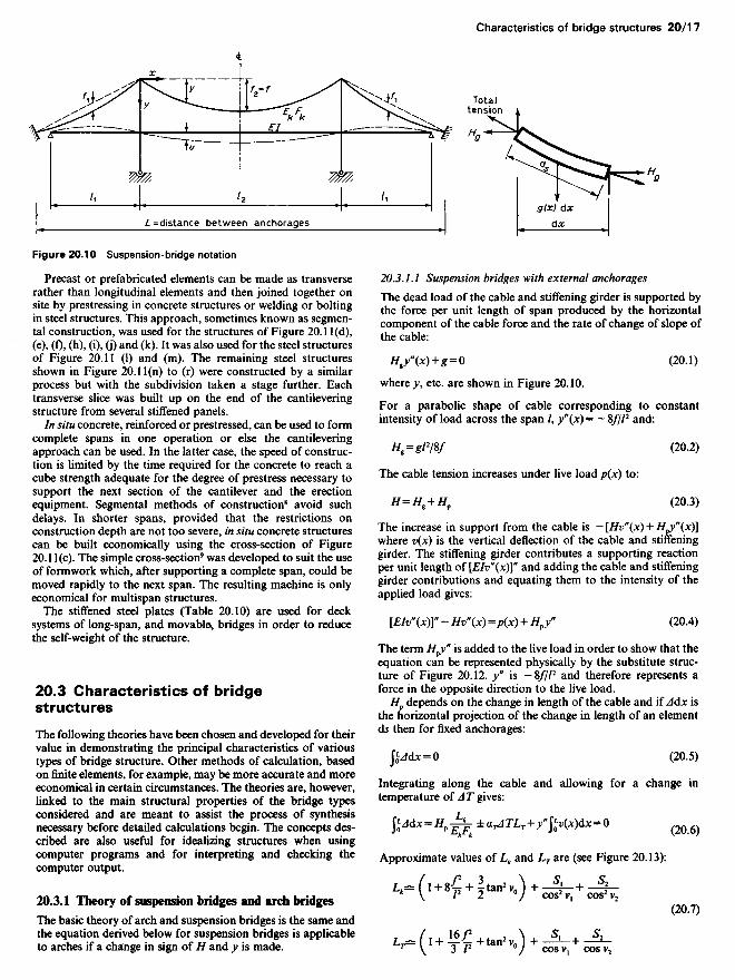
Figure 20.10 Suspension-bridge notation
Precast or prefabricated elements can be made as transverserather than longitudinal elements and then joined together onsite by prestressing in concrete structures or welding or boltingin steel structures. This approach, sometimes known as segmen-tal construction, was used for the structures of Figure 20.1 l(d),(e), (f), (h), (i), (j) and (k). It was also used for the steel structuresof Figure 20.11 (1) and (m). The remaining steel structuresshown in Figure 20.11(n) to (r) were constructed by a similarprocess but with the subdivision taken a stage further. Eachtransverse slice was built up on the end of the cantileveringstructure from several stiffened panels.
In situ concrete, reinforced or prestressed, can be used to formcomplete spans in one operation or else the cantileveringapproach can be used. In the latter case, the speed of construc-tion is limited by the time required for the concrete to reach acube strength adequate for the degree of prestress necessary tosupport the next section of the cantilever and the erectionequipment. Segmental methods of construction8 avoid suchdelays. In shorter spans, provided that the restrictions onconstruction depth are not too severe, in situ concrete structurescan be built economically using the cross-section of Figure20.1 l(c). The simple cross-section9 was developed to suit the useof formwork which, after supporting a complete span, could bemoved rapidly to the next span. The resulting machine is onlyeconomical for multispan structures.
The stiffened steel plates (Table 20.10) are used for decksystems of long-span, and movable, bridges in order to reducethe self-weight of the structure.
20.3 Characteristics of bridgestructures
The following theories have been chosen and developed for theirvalue in demonstrating the principal characteristics of varioustypes of bridge structure. Other methods of calculation, basedon finite elements, for example, may be more accurate and moreeconomical in certain circumstances. The theories are, however,linked to the main structural properties of the bridge typesconsidered and are meant to assist the process of synthesisnecessary before detailed calculations begin. The concepts des-cribed are also useful for idealizing structures when usingcomputer programs and for interpreting and checking thecomputer output.
20.3.1 Theory of suspension bridges and arch bridges
The basic theory of arch and suspension bridges is the same andthe equation derived below for suspension bridges is applicableto arches if a change in sign of H and y is made.
20.3.1.1 Suspension bridges with external anchorages
The dead load of the cable and stiffening girder is supported bythe force per unit length of span produced by the horizontalcomponent of the cable force and the rate of change of slope ofthe cable:
#,y(*) + * = 0 (20.1)
where y, etc. are shown in Figure 20.10.
For a parabolic shape of cable corresponding to constantintensity of load across the span /, y"(x) = - 8///2 and:
Hg=glW (20.2)
The cable tension increases under live load p(x) to:
H=HK + Hp (20.3)
The increase in support from the cable is — [Hv" (x) + H^(X)]where v(x) is the vertical deflection of the cable and stiffeninggirder. The stiffening girder contributes a supporting reactionper unit length of [EIv"(x)]" and adding the cable and stiffeninggirder contributions and equating them to the intensity of theapplied load gives:
[EIv"(x)]" - Hv"(x) =p(x) + Hfy" (20.4)
The term H^y" is added to the live load in order to show that theequation can be represented physically by the substitute struc-ture of Figure 20.12. y" is — 8///2 and therefore represents aforce in the opposite direction to the live load.
Hp depends on the change in length of the cable and if A&x isthe horizontal projection of the change in length of an elementds then for fixed anchorages:
JjJdX = O (20.5)
Integrating along the cable and allowing for a change intemperature of A T gives:
fcW*-*Pl^ iMJV^fr-Wfc-O (20.6)
Approximate values of Lk and L7 are (see Figure 20.13):
L^ (l+8-£ + ̂ tan2 V0) + -^-+ ~4-* \ /2 2 °/ COS2V1 COS2V2
(20.7)
L1^(I+ ̂ + tan2V0) +JjU JL.
Totaltension
L= distance between anchorages