bringing paladin into the 21 century - ndia mich
TRANSCRIPT
2014 NDIA GROUND VEHICLE SYSTEMS ENGINEERING AND TECHNOLOGY
SYMPOSIUM VEHICLE ELECTRONICS AND ARCHITECTURE (VEA) TECHNICAL SESSION
AUGUST 12-14, 2014 - NOVI, MICHIGAN
BRINGING PALADIN INTO THE 21st CENTURY
Bruce Bailey BAE Systems Endicott, NY
Mark R. Miller
Gordon Brinton Eric Swartz
BAE Systems York, PA
George Hamilton TARDEC
Warren, MI
Paul Uetz Eric Jochum
Dennis Regmont PM-SPHS Warren, MI
ABSTRACT The M109A7/M992A3 Paladin Integrated Management (PIM) is a
sustainment program designed to bring the M109 Family of Vehicles (FOV) up-
to-date and extend the service life of the fleet. PIM consists of the sustainment
and upgrade of two military tracked vehicles; the Paladin M109A6 Self Propelled
Howitzer (SPH) and the M992A2 Carrier Ammunition, Tracked (CAT). The
M109A7/M992A3 program is engineered to improve readiness, avoid component
obsolescence, and increase sustainability. These changes will increase the
performance of the M109A7/M992A3, eliminate obsolescence issues associated
with supplying new parts to the M109A6 and M992A2, and ease the logistics
burden within the Artillery Brigade Combat Team (ABCT) through commonality
of spares parts. The PIM project has been a multi-phase project with
development expected to continue into 2015.
INTRODUCTION
The M109A7 and M992A3 significantly
enhances the reliability, mission maintainability,
sustainability, and responsiveness of the M109A6
and M992A2 while establishing current and future
commonality within the US. Army Armored
Brigade Combat Team (ABCT). Beyond the
Paladin Digital Fire Control System, previous
upgrades hadn’t altered much of the M109’s
1950’s chassis configuration [1]. To meet the
present day performance requirements as well as
establishing a path to implementing future
capability and growth initiatives, it was clear that
the M109A6 needed to evolve from the legacy
analog heterogeneous implantation to a scalable
digital implementation. The platform needed to
meet the following requirements:
Provide an open and scalable architecture
that would network various subsystems
and Line Replaceable Units (LRUs)
Proceedings of the 2014 Ground Vehicle Systems Engineering and Technology Symposium (GVSETS)
Page 2 of 14
Seamlessly combine existing components
with emerging technologies
Maintain a reduced lifecycle cost through
logistics support
The M109A6 Paladin Integrated Management
(PIM) sustainment program electrical power
management and vehicle health management
requirements dictated the electrical/electronic
architecture selected. The M109A6 Self-Propelled
Howitzer (SPH) consisted of a 650A, 28Vdc belt-
driven generator, four (4) 6T Maintenance Free
(MF) batteries, thermal circuit breaker low voltage
power distribution and discrete analog
control/status for automotive/auxiliary/chassis
vehicle systems.
Power Generation, Distribution and Management
Due to the howitzer’s vehicle maximum
electrical load of greater than 27kW and the
Statement of Work (SOW) requirement, ‘The
M109A6 PIM electrical power generation shall
have fifty percent (50%) reserve capacity for
future growth at the time of Initial Operational
Capability (IOC), for a total electrical power
generation of 41kW. In order to meet this
electrical power generation requirement dual
28Vdc generators would be necessary. This
would have required twice the current volume, an
innovative design to drive the dual alternator
configuration and increased volume to
accommodate the output cabling to the power
distribution subsystem. These issues led the BAE
Platforms & Services, York, PA electrical power
generation and management design team to
establish a joint interdivisional effort with BAE
Systems, HybriDrive Solutions, in Endicott, NY
for a different technical approach.
BAE Systems, HybriDrive Solutions was
manufacturing Hybrid Electric Drive (HED)
power electronic components for the transit bus
market and leveraged this technology to
design/integrate a Common Modular Power
System (CMPS) onto a Stryker vehicle platform
which utilized a PTO-gear driven 72kW ISG.
BAE Systems ES and TARDEC believed a CMPS
was possible where all combat vehicles could
utilize a common power architecture and common
components where possible. The M109A7
electrical power generation and management
design team recognized this as an opportunity to
integrate a proven CMPS on the M109A7 vehicle
platform. The BAE Systems interdivisional
design team first had to review the power usage
and power management capability gap analysis for
the Stryker, M109A7, M992A3 and Bradley
Fighting Vehicle (BFV) Family of Vehicles
(FOVs). Electrical power generation system
designs were then developed for each of the
vehicle platforms. Finally, common power system
components between the various platforms were
identified leading to the M109A7/M992A3
electrical power generation, distribution and
management system design.
The M109A7 Common Modular Power System
consists of a 70kW High Voltage (HV) generator,
four (4) Hawker Batteries, a 70kW generator
inverter, two (2) 10kW Bi-Directional Converters,
High Voltage Distribution Box (HVDB) and three
(3) Vehicle Control and Distribution Modules
(VCDMs) which provide Solid State Power
Controller (SSPC) Cards for 28Vdc power
distribution. The electrical power architecture
includes a 610Vdc HV bus and 28Vdc Low
Voltage (LV) bus providing input electrical power
to the HVDB and VCDMs. A SAE J1939
CANbus provides electrical power control/status
communication and the electrical power system
diagnostics is communicated via GB Ethernet.
The 70kW HV generator and four (4) Hawker
AGM Batteries provide the electrical power
generation for the CMPS. The 70kW generator
inverter inverts the generator AC voltage to +/-
Proceedings of the 2014 Ground Vehicle Systems Engineering and Technology Symposium (GVSETS)
Page 3 of 14
305 (610Vdc) and the 10kW Bi-Directional
Converters convert 610Vdc to 28Vdc. The 70kW
generator inverter and two (2) 10kW Bi-
Directional Converters provide the electrical
power inversion and conversion for the CMPS.
The 36.6kW HVDB and three (3) VCDMs provide
the electrical power distribution for the CMPS.
The 70kW generator provides the CMPS electrical
power management which includes fault
monitoring, load management, battery monitoring
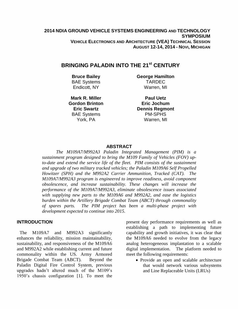
and electrical power control. Figure 1 shows the
key components of the M109A7 power
generation, distribution and management
subsystems.
Vehicle Power Manager
Power Manager Functions
Load Management Energy Storage CtrlPower Control Aux Pwr Ctrl
Fault Monitoring Status Reporting
Power Sources Sub-Systems
Integrated Starter
Generator(ISG)
Vehicle Battery
System
Energy Storage
System
Auxiliary Power
Generation
Loads & Distribution
Vehicle Battery
Charger
Energy Storage Sys
Charger
Network/Data
Network/Data
To vehicle Mission & Weapons Computers
Network/Data
SV-1 FUNCTIONAL PERSPECTIVE
DC-DC Converter(s)120V/208V 60Hz
Inverter(s)
Power Distribution
Controller(s)
Power Conversion Sub-Systems
Network/Data
Hi Voltage
28 V
Hi Voltage
28 V
Hi Voltage
28 V
To individual vehicle loads:
Vehicle Accessories - Lights, Motors, Fans
Mission Loads - Computers, Radios, Diplays
Weapson Loads - Computers, Fire Controllers, etc.Thermal Management System
NBC System
etc.
28 V
Figure 1- M109A7 power generation,
distribution and management subsystems
Digital Backbone
The M109A6 SPH’s automotive, auxiliary, and
electrical power subsystems were analog
providing discrete input/output to the non-smart
electrical Line Replaceable Units (LRU)s. The
SOW required, ‘The M109A6 PIM shall have a
Vehicle Health Management System (VHMS)
which monitors and reports the health of the
vehicle and its subsystems at a minimum to
include Fire Control, Engine, Transmission, Power
Management and Electric Drive in accordance
with the Heavy Brigade Combat Team (HBCT)
VHMS Vehicle Segment Requirements
Specification document …’ and Power
Management System SOW paragraph that states
‘The power management system shall manage
electrical power distribution and utilization,
monitor and protect the power system and loads,
provide host vehicle electrical system status
information to the crew and maintenance
personnel’. These requirements resulted in the
decision to implement a vehicle platform with a
digital backbone.
Electric replaces Hydraulic
The M109A7 replaces the M109A6’s legacy
hydraulically-operated elevation and azimuth
drives with electric drive technology leveraged
from the Future Combat Systems 155mm NLOS-
C (Non-Line-of-Sight Cannon). Replacing the
hydraulics with electrically operated drives
drastically reduces maintenance and eases the
logistics burden. Manual backups mitigate loss of
electrical power. Additional maintainability and
reliability improvements were gained by the
replacement of the slip ring with a Cable
Management System (CMS), an articulating
conduit for the transfer of both high and low
voltage power and networked communications
between the chassis hull and cab.
ELECTRICAL/ELECTRONICS EVOLUTION FROM THE M109A6
Overview of High Voltage Power System and Components on the M109A7/M992A3
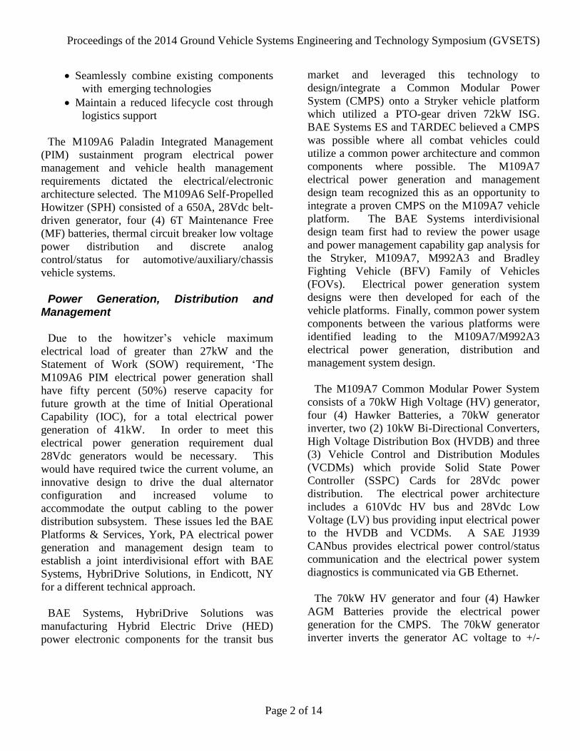
The electrical power of the PIM vehicle is
separated into two systems as shown in Figure 2.
The first system consists of equipment generating
and utilizing high voltage power, which includes
the Generator, Generator Inverter (GINV), High
Voltage Distribution Box (HVDB), Bi-Directional
Proceedings of the 2014 Ground Vehicle Systems Engineering and Technology Symposium (GVSETS)
Page 4 of 14
Converter (BiDi), Paladin Electric Servo
Amplifier (PESA) and the Microclimate
Conditioning System (MCS). The majority of the
components are located in the Engine
Compartment and the Weapons Controller
Compartment. Various HV cables and motors are
located in the crew compartment.
Figure 2- High Voltage Power Systems
The second electrical power system operates all
other systems using 28V power. The 28V low
voltage power system is dependent on the high
voltage system, except for power from the
batteries. All generated power begins as high
voltage power, and is turned into low voltage
power at the BiDi. The SPH has two BiDi’s, and
the CAT has one BiDi.
Due to the SOW requirements, ‘Vehicle shall be
capable of operating the Communications,
Navigation, Automatic Fire Control Systems,
exclusive of gun drives, for a minimum of 90
minutes…. (Standby State Mode)’ and ‘Vehicle
batteries shall have sufficient capacity to start the
vehicle engine at the end of the 90 minute battery
operation period’, four (4) Hawker AGM Batteries
with 1225 cold cranking amps were recommended
from the battery trade to meet these requirements.
High Voltage Power System
The high voltage power system contains both
28V and 610VDC power. The 610VDC power is
used to operate the equipment and the 28V power
is for circuits used to control and monitor the
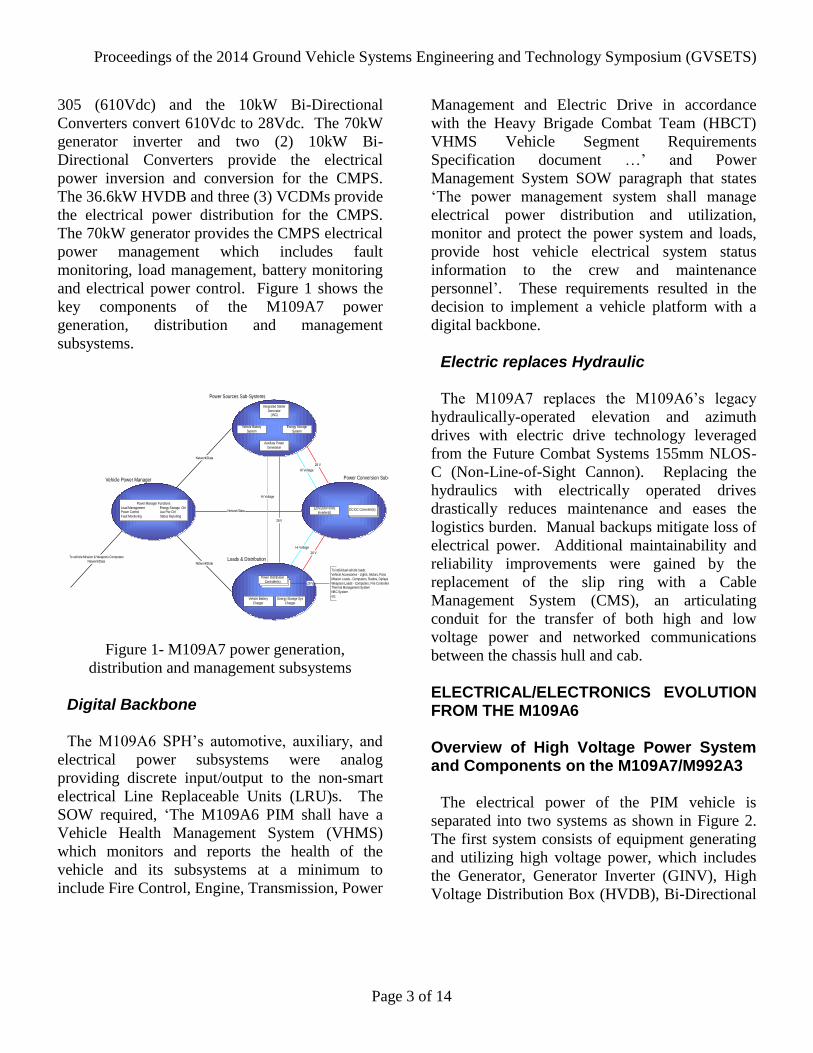
610VDC power. Figure 3 shows the high level
architecture of the high voltage power system.
Figure 3 - High Voltage System Architecture
Generator
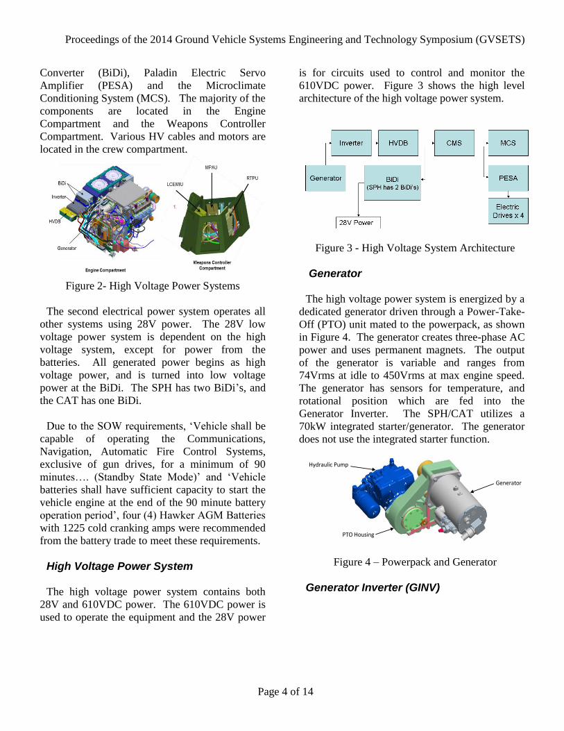
The high voltage power system is energized by a
dedicated generator driven through a Power-Take-
Off (PTO) unit mated to the powerpack, as shown
in Figure 4. The generator creates three-phase AC
power and uses permanent magnets. The output
of the generator is variable and ranges from
74Vrms at idle to 450Vrms at max engine speed.
The generator has sensors for temperature, and
rotational position which are fed into the
Generator Inverter. The SPH/CAT utilizes a
70kW integrated starter/generator. The generator
does not use the integrated starter function.
Hydraulic Pump
PTO Housing
Generator
Figure 4 – Powerpack and Generator
Generator Inverter (GINV)
Proceedings of the 2014 Ground Vehicle Systems Engineering and Technology Symposium (GVSETS)
Page 5 of 14
The Generator Inverter (GINV) converts the 3-
Phase AC power from the generator to 610VDC.
The 610VDC output is a direct current, two-wire
system having a nominal output of 610VDC. The
610VDC is balanced with high impedance with
respect to chassis ground in the GINV such that
the positive output is nominally +305VDC and the
negative output is nominally -305VDC. The
GINV has ground fault detection capability for the
high voltage bus, diagnostic sensors for internal
voltage, current and temperatures, as well as
sensors for generator voltage, current, and
temperature measurement. The GINV also
provides over current, over voltage, and under
voltage protection for the 610VDC high voltage
bus. The GINV will disconnect or not allow high
voltage power at its output if any sensors show
that they are operating outside of the defined
envelope.
The HV power from the GINV is also controlled
by an interlock continuity loop circuit. The
interlock circuit is continuous whenever the HV
system is assembled properly. Once internal
diagnostics are complete and the GINV is
receiving power from the generator, the GINV
will release its 610VDC power.
The high voltage power from the GINV is passed
to the HVDB which distributes it to the rest of the
system.
High Voltage Distribution Box (HVDB)
The HVDB takes power from the Inverter and
distributes it to the BiDi, the PESA (SPH Only),
and the MCS. In the SPH, the HVDB distributes
power to two BiDi’s. In the CAT, the HVDB
distributes power to one BiDi.
The HVDB releases power to the PESA and to
the MCS individually, when those devices
command it. The command is initiated through
interlock loop continuity which is controlled
within the PESA and the MCS. When the MCS
and/or the PESA interlock loop are closed, the
HVDB releases power to the respective system.
In addition to distributing power to the various
systems, the HVDB also places current limiting
fuses on each high voltage output terminal which
protect against downstream short circuits. There
are individual fuses on the high-side (+305V) as
well as the low side (-305V) of each output.
Additionally, if the HVDB does not react to a
short circuit, there is still protection provided by
the GINV.
The HVDB also includes an EMI filter for power
traveling to the MCS and to the PESA.
Bi-Directional Converter (BiDi)
The SPH utilizes two BiDi’s, the CAT uses one.
The BiDi takes 610VDC power from the HVDB
and converts it to 28V power in order to supply
the low voltage components of the SPH/CAT.
Cable Management System (CMS) (SPH Only)
The high voltage circuit consists of equipment in
the hull and in the cab of the SPH vehicle. The
CMS links the two areas, allowing the cab to
rotate in relation to the hull. Cables come into the
cable management system from the hull
disconnect bracket, and attach to the cab
disconnect bracket when they leave the system.
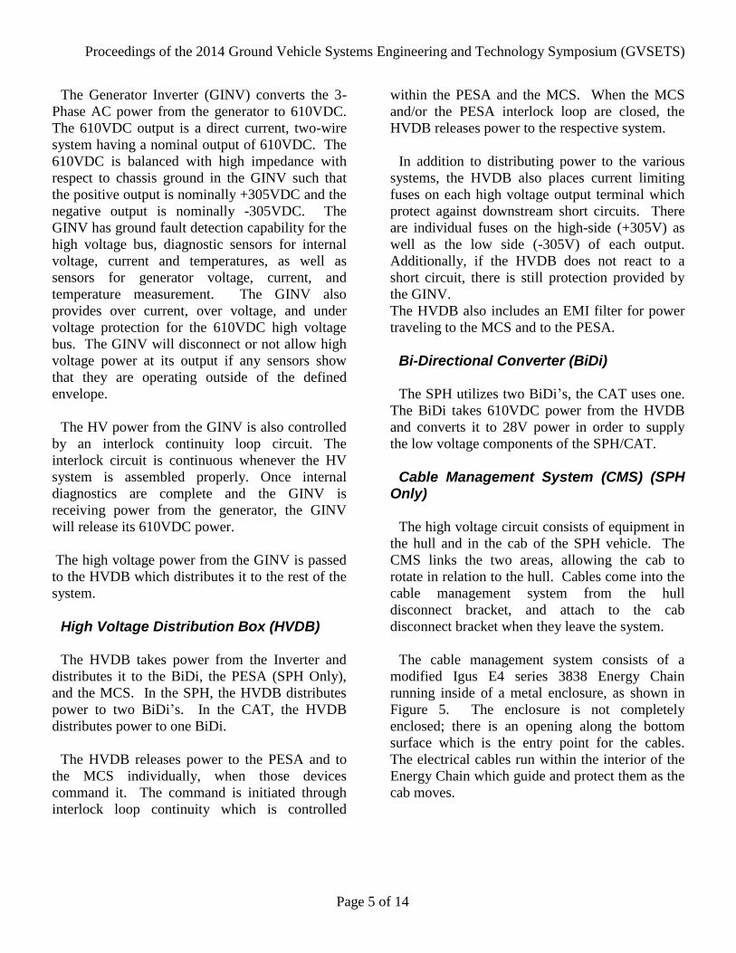
The cable management system consists of a
modified Igus E4 series 3838 Energy Chain
running inside of a metal enclosure, as shown in
Figure 5. The enclosure is not completely
enclosed; there is an opening along the bottom
surface which is the entry point for the cables.
The electrical cables run within the interior of the
Energy Chain which guide and protect them as the
cab moves.
Proceedings of the 2014 Ground Vehicle Systems Engineering and Technology Symposium (GVSETS)
Page 6 of 14
Figure 5 - Energy Chain system in the PIM SPH
enclosure (top of enclosure not shown)
High and low voltage power cables are both
routed through the same Energy Chain. They are
divided within the device by separators which
keep the cables organized into channels. The
cables are routed in the Energy Chain, and the
energy chain moves in a manner such that the
cables keep their arrangement to each other in the
vertical plane. There are two High Voltage cables
which run through the CMS. One cable serves the
power to the PESA, and one cable serves the
power to the MCS.
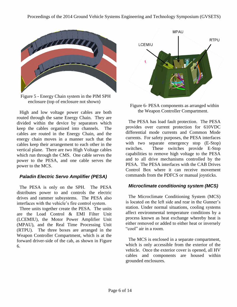
Paladin Electric Servo Amplifier (PESA)
The PESA is only on the SPH. The PESA
distributes power to and controls the electric
drives and rammer subsystems. The PESA also
interfaces with the vehicle’s fire control system.
Three units together create the PESA. The units
are the Load Control & EMI Filter Unit
(LCEMIU), the Motor Power Amplifier Unit
(MPAU), and the Real Time Processing Unit
(RTPU). The three boxes are arranged in the
Weapon Controller Compartment, which is at the
forward driver-side of the cab, as shown in Figure
6.
Figure 6- PESA components as arranged within
the Weapon Controller Compartment.
The PESA has load fault protection. The PESA
provides over current protection for 610VDC
differential mode currents and Common Mode
currents. For safety purposes, the PESA interfaces
with two separate emergency stop (E-Stop)
switches. These switches provide E-Stop
capabilities to remove high voltage to the PESA
and to all drive mechanisms controlled by the
PESA. The PESA interfaces with the CAB Drives
Control Box where it can receive movement
commands from the PDFCS or manual joysticks.
Microclimate conditioning system (MCS)
The Microclimate Conditioning System (MCS)
is located on the left side and rear in the Gunner’s
station. Under normal situations, cooling systems
affect environmental temperature conditions by a
process known as heat exchange whereby heat is
either removed or added to either heat or inversely
“cool” air in a room.
The MCS is enclosed in a separate compartment,
which is only accessible from the exterior of the
vehicle. Once the exterior cover is opened, all HV
cables and components are housed within
grounded enclosures.
Proceedings of the 2014 Ground Vehicle Systems Engineering and Technology Symposium (GVSETS)
Page 7 of 14
High Voltage Safety and the M109A7/M992A3
The high voltage systems of the SPH and CAT
are capable of mitigating hazardous situations and
protecting equipment and personnel from potential
injury. These safety feature capabilities include
aspects of ground fault protections, interlocks,
high voltage/energy discharge protection,
awareness, and training. In addition, the HV
components are designed to withstand partial and
total submersion.
These design requirements are intended to
prevent inadvertent or accidental contact with
hazardous voltages or to prevent damage or injury
from the uncontrolled release of electrical energy
during normal operation, maintenance, and
abnormal operating conditions.
Ground Fault Protections
Ground fault protection systems have been
designed into the Generator Inverter (GINV) and
PIM Electric Servo Amplifier (PESA). Multiple
layers of insulation, shielding and conduit if
compromised help trigger a ground fault condition
and safely shut down HV/HE in the system
The GINV high voltage output is a two wire
source which floats but is centered with respect to
chassis ground or 0V (centered by balancing
resistors in the GINV). Its differential output
voltage is regulated to be 610VDC resulting in its
positive output being at a potential of +305V with
respect to chassis ground and its negative output
being at a potential -305V with respect to chassis
ground.
The GINV defines a ground fault as a shift in the
+/-305V high voltage outputs with respect to
chassis ground (0V). The differential voltage is
monitored to account for normal regulation
tolerance of the 610VDC high voltage bus when
setting the trip point for the -305V output to
chassis ground threshold measurement.
When a ground fault to chassis occurs, it is
expected to pull the faulted output toward chassis
ground or 0V. In this case the potential of the
opposite line would be pulled away from 0V in
order to maintain the 610VDC nominal
differential regulation point of the GINV output
(Example, if the -305V line has a ground fault, it
should go toward 0V and the opposite line should
go toward +610V). Therefore by monitoring the -
305V output with respect to chassis ground a shift
in either +/305V output caused by a ground fault
to chassis ground can be detected.
Upon detection of a ground fault the GINV will
shut down and disconnect from the 610VDC high
voltage output in less than ~23.5mS.
High Voltage Interlock Circuits
Hazardous Voltage electrical circuits are
provided with an appropriate set of Automatic
disconnects, Manual disconnects and or Interlocks
to prevent inadvertent contact with the hazardous
voltage. There is a low voltage interlock wire
within the cables that carry HV power between the
HV components. If broken, the Low Voltage
(LV) interlocks in multiple subsystems shuts down
HV from the GINV.
Interlock circuits are utilized as a safety feature.
By incorporating an interlock circuit within the
same cables used for high voltage power, the
system can monitor the high voltage cables and
connections. Discontinuity in the interlock circuit
will show if a high voltage cable has been severed
or is not connected. A discontinuity in the
interlock circuit will remove power or prevent
power from being applied.
Since a break in the interlock circuit indicates an
unsafe condition and therefore removes power,
Proceedings of the 2014 Ground Vehicle Systems Engineering and Technology Symposium (GVSETS)
Page 8 of 14
other safety features (emergency stops, equipment
enclosures) are integrated into the interlock circuit
which will also break it.
All HV cables on the SPH/CAT are interlocked.
If any connector is unplugged during operation the
HV system will at a minimum shut down that
portion of the HV:
If the MCS HV cable is disconnected, the
HVDB MCS contactor will open
disconnecting power to the MCS
If the PESA HV cable is disconnected, the
HVDB PESA contactor will open
disconnecting power to the PESA
If any other HV cable between the GINV,
HVDB and BIDI’s are disconnected the:
o GINV output contactor will open
eliminating HV from exposed GINV
pins/sockets
o BIDI input contactors will open
eliminating HV from exposed BIDI
pins/sockets
o HVDB will bleed the HV down to <50V in
less than 2 seconds from exposed HVDB
pins/sockets
o The only voltage that will not shut off is
the generator 3 phase output, if
disconnected the HV system will shut off
but AC HV will still be present on
generator output sockets.
High Voltage/Energy Discharge Protection
When a short circuit occurs within the HV
system (+305 line touching -305 line) an arc flash
can occur. Temperatures during an electrical arc
are severely high (up to 35000°F). This heat
causes a sudden expansion of air, and the
vaporization of the conducting material.
Personnel can be injured from the heat of the arc,
or by the resulting sound and explosion caused by
the rapid expansion of air and other materials. On
the SPH/CAT, arc hazards are mitigated by the
limited energy within the system as well as the
speed with which energy is safely shut down in
the event of an arc.
Hazardous voltage cables, busses or wires routed
within unoccupied vehicle spaces are insulated,
firmly mounted, abrasion resistant and are
designed and installed to minimize service
personnel exposure to hazardous voltage circuits.
For hazardous voltage that is routed through
crew and passenger compartments, the design
includes metal HV cable guards that provide
physical separation of the hazardous voltage wires
from the personnel. The cables from the HVDB to
the PESA and to the MCS are completely enclosed
in cable guards while they are routed through the
crew space. The cables from the PESA to the
electric drives are enclosed for a significant
majority of the area that they are routed through
crew space.
The high voltage cable guard structure must be
capable of protecting the crew from a worst case
arc blast internal to the cable. The high voltage
cable guard cannot rupture or cannot deform to the
point of visually exposing the cable to the Crew.
Modeling and simulation results show that 3/16”
5083-H321 or 5052-H32 aluminum material cable
guard provides sufficient protection to the Crew in
all cases. An arc blast event, with an equivalent
130 mg TNT, will not cause any permanent
structural damage to the cable guard in either of
the aluminum material options.
Awareness
All of the SPH/CAT high voltage wiring harness
coverings (+/-300 600 VDC generator / motor
wires and buss bars) are identified with the use of
orange color conduit or sleeving/tubing and
boots/transitions. Individual high voltage cables
are also permanently marked with the voltage
level as shown in Figure 7.

Proceedings of the 2014 Ground Vehicle Systems Engineering and Technology Symposium (GVSETS)
Page 9 of 14
Figure 7 – High Voltage Warning on Electrical
Wiring Harnesses
In addition, High Voltage components (LRUs)
on the SPH/CAT include danger stickers as shown
in Figure 8 to notify the crew and maintainers
about the risk of electric shock.
Figure 8 – Danger sticker applied to High
Voltage LRUs
Training
All operators/maintainers on the SPH/CAT must
be trained regarding the HV system. Operators
and maintainers must have verified knowledge of
the system and the hazards present during the
operation or maintenance of the vehicles.
Distributed vs. Federated Architecture
Although it was clear that a flexible architecture
was needed, key decisions had to be made before
holistically advancing to a digital architecture.
Through the years, the M109 had evolved
primarily in a bottom-up fashion driven by the
opportunities to bolt on new capability. The
M109A7/ M992A3 design includes a new chassis,
engine, transmission, suspension, tracks, and
steering system which leverage common
components from the Bradley Fighting Vehicle.
The M109A7 / M992A3 vastly differs from its
predecessor platforms with new vision of net-
centricity, diagnostics, sustained growth potential,
cost stewardship, and obsolescence avoidance all
of which promoted a clean-sheet opportunity for
top-down design. Top-down design encompasses
the big picture for meeting legacy, current and
future forecasted requirements.
Factors such as reliability, cost, ease of
maintenance, and scalability all played a part in
confirming the next generation architecture for the
M109A7/M99A2A3. A primary design goal was
to maintain high reliability and mission readiness,
limit variables included within the critical path of
mission critical capabilities. The architecture must
cost effectively and reliably support the
M109A7/M99A2A3’s mission critical functions to
shoot, move, and communicate. If vehicle power
is lost, degraded mode and/or manual backups
must be available to meet mission requirements. A
secondary design goal was to leverage common
components as much as possible to reduce the
logistic burdens on the battlefield.
Federated/centralized options were considered
but deemed cost prohibitive due to the LRU cost
plus the cost of integrating additional wiring
harnesses as compared with the distributed
approach. The integration of multiple centralized
LRUs also posed too many challenges to Size,
Weight, and Power (SWAP) reduction initiatives.
Proceedings of the 2014 Ground Vehicle Systems Engineering and Technology Symposium (GVSETS)
Page 10 of 14
Given the fact that a digital architecture was
required for the M109A7 SPH an informal trade
was conducted to determine a distributed digital
architecture which supports the Victory
Architecture Initiative or a Federated (Point
Solution) digital architecture. The Vetronics
Control and Distribution Module (VCDM) is the
remote terminal module for the Distributed
Architecture and the Digital Vehicle Distribution
Box (DVDB) is the Point Solution for the
Federated Architecture.
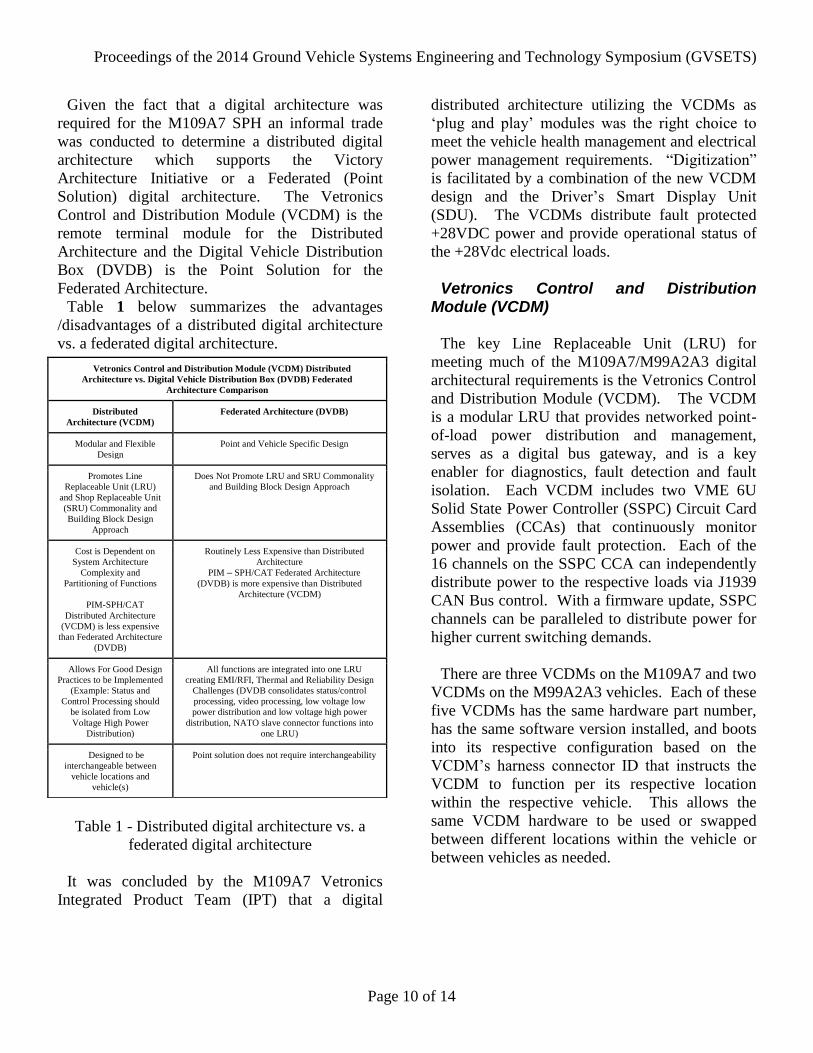
Table 1 below summarizes the advantages
/disadvantages of a distributed digital architecture
vs. a federated digital architecture.
Table 1 - Distributed digital architecture vs. a
federated digital architecture
It was concluded by the M109A7 Vetronics
Integrated Product Team (IPT) that a digital
distributed architecture utilizing the VCDMs as
‘plug and play’ modules was the right choice to
meet the vehicle health management and electrical
power management requirements. “Digitization”
is facilitated by a combination of the new VCDM
design and the Driver’s Smart Display Unit
(SDU). The VCDMs distribute fault protected
+28VDC power and provide operational status of
the +28Vdc electrical loads.
Vetronics Control and Distribution Module (VCDM)
The key Line Replaceable Unit (LRU) for
meeting much of the M109A7/M99A2A3 digital
architectural requirements is the Vetronics Control
and Distribution Module (VCDM). The VCDM
is a modular LRU that provides networked point-
of-load power distribution and management,
serves as a digital bus gateway, and is a key
enabler for diagnostics, fault detection and fault
isolation. Each VCDM includes two VME 6U
Solid State Power Controller (SSPC) Circuit Card
Assemblies (CCAs) that continuously monitor
power and provide fault protection. Each of the
16 channels on the SSPC CCA can independently
distribute power to the respective loads via J1939
CAN Bus control. With a firmware update, SSPC
channels can be paralleled to distribute power for
higher current switching demands.
There are three VCDMs on the M109A7 and two
VCDMs on the M99A2A3 vehicles. Each of these
five VCDMs has the same hardware part number,
has the same software version installed, and boots
into its respective configuration based on the
VCDM’s harness connector ID that instructs the
VCDM to function per its respective location
within the respective vehicle. This allows the
same VCDM hardware to be used or swapped
between different locations within the vehicle or
between vehicles as needed.
Vetronics Control and Distribution Module (VCDM) Distributed
Architecture vs. Digital Vehicle Distribution Box (DVDB) Federated
Architecture Comparison
Distributed
Architecture (VCDM) Federated Architecture (DVDB)
Modular and Flexible
Design Point and Vehicle Specific Design
Promotes Line
Replaceable Unit (LRU)
and Shop Replaceable Unit
(SRU) Commonality and
Building Block Design
Approach
Does Not Promote LRU and SRU Commonality
and Building Block Design Approach
Cost is Dependent on
System Architecture
Complexity and
Partitioning of Functions
PIM-SPH/CAT
Distributed Architecture
(VCDM) is less expensive
than Federated Architecture
(DVDB)
Routinely Less Expensive than Distributed
Architecture PIM – SPH/CAT Federated Architecture
(DVDB) is more expensive than Distributed
Architecture (VCDM)
Allows For Good Design
Practices to be Implemented
(Example: Status and
Control Processing should
be isolated from Low
Voltage High Power
Distribution)
All functions are integrated into one LRU
creating EMI/RFI, Thermal and Reliability Design
Challenges (DVDB consolidates status/control
processing, video processing, low voltage low
power distribution and low voltage high power
distribution, NATO slave connector functions into
one LRU)
Designed to be
interchangeable between
vehicle locations and
vehicle(s)
Point solution does not require interchangeability
Proceedings of the 2014 Ground Vehicle Systems Engineering and Technology Symposium (GVSETS)
Page 11 of 14
Driver’s Display
The Smart Display Unit (SDU) is a 10.4” display
and computer integrated into one package. The
SDU runs application software and is capable of
performing video and graphics processing. The
SDU includes gigabit Ethernet, CAN Bus, serial,
USB, RS-170 video, RGB video, audio input and
output, and a removable Solid State Disk (SSD).
The SDU provides the driver with a virtual
instrument cluster and serves as the main
diagnostics interface to support fault detection and
isolation.
MIGRATION OF THE SOFTWARE ARCHITCTURE
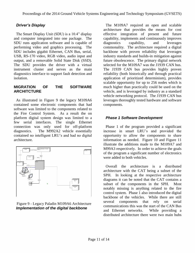
As illustrated in Figure 9 the legacy M109A6
contained some electronic components that had
software was limited to the components related to
the Fire Control System. As a result the on
platform digital system design was limited to a
few serial interfaces. The single Ethernet
connection was only used for off-platform
diagnostics. The M992A2 vehicle essentially
contained no intelligent LRU’s and had no digital
architecture.
Figure 9 - Legacy Paladin M109A6 Architecture
Implementation of the digital backbone
The M109A7 required an open and scalable
architecture that provides the means for cost
effective integration of present and future
capability, implements and continuously improves
diagnostics capability, and leverages
commonality. The architecture required a digital
backbone with proven reliability that leverages
industry standards and builds-in mitigation against
future obsolescence. The primary digital network
selected for the M109A7 was the J1939 CAN bus.
The J1939 CAN bus provides highly proven
reliability (both historically and through practical
application of prioritized determinism), provides
scalable opportunity for up to 256 nodes which is
much higher than practically could be used on the
vehicle, and is leveraged by industry as a standard
vehicle networking protocol. The J1939 CAN bus
leverages thoroughly tested hardware and software
components.
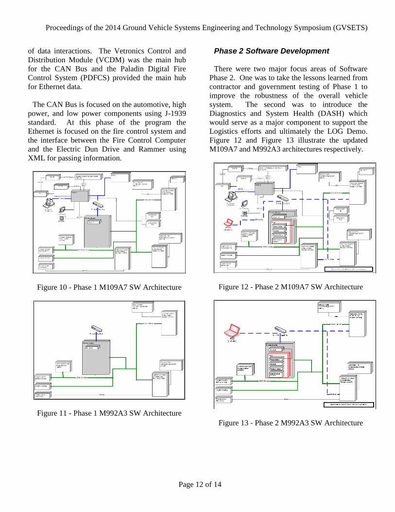
Phase 1 Software Development
Phase 1 of the program provided a significant
increase in smart LRU’s and provided the
opportunity to allow the components to share
information as needed. Figure 10 and Figure 11
illustrate the additions made to the M109A7 and
M99A3 respectively. In order to achieve the goals
of the program a significant number of electronics
were added to both vehicles.
Overall the architecture is a distributed
architecture with the CAT being a subset of the
SPH. In looking at the respective architecture
diagrams it can be noted that the CAT contains a
subset of the components in the SPH. Most
notably missing is anything related to the fire
control system. Phase 1 also introduced the digital
backbone of the vehicles. While there are still
several components that rely on serial
communications this was the start of the CAN Bus
and Ethernet networks. While providing a
distributed architecture there were two main hubs
Proceedings of the 2014 Ground Vehicle Systems Engineering and Technology Symposium (GVSETS)
Page 12 of 14
of data interactions. The Vetronics Control and
Distribution Module (VCDM) was the main hub
for the CAN Bus and the Paladin Digital Fire
Control System (PDFCS) provided the main hub
for Ethernet data.
The CAN Bus is focused on the automotive, high
power, and low power components using J-1939
standard. At this phase of the program the
Ethernet is focused on the fire control system and
the interface between the Fire Control Computer
and the Electric Dun Drive and Rammer using
XML for passing information.
Figure 10 - Phase 1 M109A7 SW Architecture
Figure 11 - Phase 1 M992A3 SW Architecture
Phase 2 Software Development
There were two major focus areas of Software
Phase 2. One was to take the lessons learned from
contractor and government testing of Phase 1 to
improve the robustness of the overall vehicle
system. The second was to introduce the
Diagnostics and System Health (DASH) which
would serve as a major component to support the
Logistics efforts and ultimately the LOG Demo.
Figure 12 and Figure 13 illustrate the updated
M109A7 and M992A3 architectures respectively.
Figure 12 - Phase 2 M109A7 SW Architecture
Figure 13 - Phase 2 M992A3 SW Architecture
Proceedings of the 2014 Ground Vehicle Systems Engineering and Technology Symposium (GVSETS)
Page 13 of 14
The biggest addition was the expansion of the
Ethernet bus as it provided the transport
mechanism for the data necessary to support
DASH. However since there are a large number
of subsystems with no access to the Ethernet there
needed to be a way to communicate from DASH
to these other subsystems. The VCDM was
originally designed to provide the solution to
address this need.
The VCDM was designed with two
microprocessors. One of the microcontroller
boards was designated to perform all of the low
voltage power distribution tasks. The second
microcontroller board contained all the hardware
necessary to support Ethernet communications as
well as a dual port memory area to allow the
exchange of data between the two. As a result the
VCDM became the bridge between the CAN Bus
and the Ethernet networks on the vehicle. This
bridge network provides two way communications
with the CAN Bus subsystems which allows
DASH to send Interactive Built-In-Test (IBIT)
commands to the various subsystems as well as
receive the results.
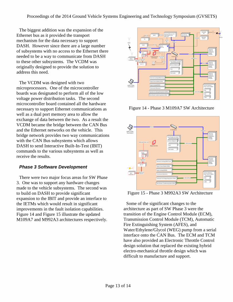
Phase 3 Software Development
There were two major focus areas for SW Phase
3. One was to support any hardware changes
made to the vehicle subsystems. The second was
to build on DASH to provide significant
expansion to the IBIT and provide an interface to
the IETMs which would result in significant
improvements in the fault isolation capabilities.
Figure 14 and Figure 15 illustrate the updated
M109A7 and M992A3 architectures respectively.
Smart Display Unit (SDU)
Dynamic Reference Unit Hybrid Replacement (DRU-H-R)
DAGR
PIK
RS-422 Gun Drive & Rammer (GDR)
Transmission Electronics
Engine Cooling (BODAS)
Engine Control Module (ECM)
Vetronics
Control &
Distribution
Module
(VCDM)
Automatic Fire Extinguishing System (AFES)
Ethernet
MicroClimatic Conditioning System (MCS)
MVRS
RS-232
SINCGARSINC
Display Unit (DU)(CoS Display)
SINCGARS(Voice)
RS-422
Dash
Drivers Display UI
Ethernet
TACKLINK
E-net Switch
Vetronics
Control &
Distribution
Module
(VCDM)
Vetronics
Control &
Distribution
Module
(VCDM)
MSD(DASH, ITEMs,Downloader)
RS-422SDLC
Ethernet
JV-5
DedicatedEthernet
C
KeypadKGV-72
DedicatedEthernet
RS-422
RS-422
FBCB2
PDCU-R(PDFCS-R)
FBCB2
DedicatedEthernet
FBCB2Transceiver
KVG SwitchDiscrete
Electronics Cooling (WEG) Pump
J-1939 CAN Bus
J-1939 CAN Bus
LVDS | USB
Common Modular Power System (CMPS)
BiDi
BiDi
GINV
AFATDS
SW Installer
Figure 14 - Phase 3 M109A7 SW Architecture
Smart Display Unit (SDU)
Vetronics
Control &
Distribution
Module
(VCDM)
Automatic Fire Extinguishing System (AFES)
MicroClimatic Conditioning System (MCS)
Dash
Drivers Display UI
EthernetE-net Switch
Vetronics
Control &
Distribution
Module
(VCDM)
MSD(DASH, IETMs,Downloader)
Ethernet
KGV-72
DedicatedEthernet
BFT2Transceiver
DedicatedEthernet
Display Unit (DU)
JV-5
BFT2
Dedicated Video Line
Transmission Electronics
Engine Cooling (BODAS)
Engine Control Module (ECM)
Electronics Cooling (WEG) Pump
J-1939 CAN Bus
J-1939 CAN Bus
Common Modular Power System (CMPS)
BiDi
GINV
SW Installer
Figure 15 - Phase 3 M992A3 SW Architecture
Some of the significant changes to the
architecture as part of SW Phase 3 were the
transition of the Engine Control Module (ECM),
Transmission Control Module (TCM), Automatic
Fire Extinguishing System (AFES), and
Water/Ethylene/Glycol (WEG) pump from a serial
interface onto the CAN Bus. The ECM and TCM
have also provided an Electronic Throttle Control
design solution that replaced the existing hybrid
electro-mechanical throttle design which was
difficult to manufacture and support.
Proceedings of the 2014 Ground Vehicle Systems Engineering and Technology Symposium (GVSETS)
Page 14 of 14
LESSONS LEARNED
This final overview section will identify some of
the customer, program and technical issues
encountered to design, integrate and test the
M109A7 SPH CMPS and Digital Distributed
Architecture.
High Voltage Safety
The M109A7 is the first Heavy Brigade vehicle
to go into Low Rate Initial Production (LRIP) with
a 70kW High Voltage system. A High Voltage
training program needed to be created leveraging
the Future Combat System (FCS) Hybrid Electric
Drive (HED) documentation. The USG and
industry had to develop new infrastructure,
logistics and procedures to safely operate and
maintain the M109A7 High Voltage CMPS.
Grounding and Bonding Grounding and bonding is very important when
designing and integrating a high voltage electrical
power system. Special attention is required to
make sure electrical bonds/grounds are properly
installed to avoid DC and AC ground faults.
High Voltage Maturity
As a result of the addition of the new technology
it was necessary to convince USG that the High
Voltage CMPS electronic components were at a
high enough readiness level from a technical and
manufacturing function to be fielded for the
troops.
Information Assurance
The awareness of the threat due to computer
security issues has grown significantly since the
fielding of the M109A6. As a result what was
acceptable for the previous vehicle is no longer
acceptable in today’s world. So, while the digital
architecture provided a mechanism for the
communication of information between the
various subsystems and improved overall
diagnostic capabilities it also then required
additional work to insure that the proper security
measures were satisfied.
Commonality
For each hardware commonality effort ensure
that the LRU requirements and qualification tests
encompass all necessary operational and
environmental requirements (shock & vibration,
hot and cold operational temperatures, radiated
emissions etc.) for all vehicle types being
considered.
REFERENCES
[1] Defense Industry Daily Staff, “Have Guns, will
Upgrade: The M109A7 Paladin PIM Self-
Propelled Howitzer” Defense Industry Daily,
2014.