bristol composites institute (accis) research speakers ... · pseudo-ductility of unidirectional...
TRANSCRIPT

Chair: • Marco Longana
• Ian Gent
Bristol Composites Institute (ACCIS) Research
Showcase: Session 2Speakers:• Aakash Paul (presentation not included)
• Putu Suwarta• Rita Palumbo• Jiajia Shen• Alexis Kordolemis

Pseudo-ductility of Unidirectional Thin-Ply Hybrid Composites in Longitudinal Compression
Putu Suwarta, Gergely Czél, Mohamad Fotouhi, Jakub Rycerz, Michael R. Wisnom
ACCIS conference 2018
22-11-2018
1

STIFF & LIGHTWEIGHT
2
Advantages:
Carbon Fibre Composites
Disadvantages:
BUT Failure is BRITTLE & CATASTROPHIC
Pseudo‐ductility of Unidirectional Thin Ply Hybrid Composites in Longitudinal Compression

3DUCTILITY for Safety
Gradual and progressive failure
Visible deformation beforefailure
High Performance Ductile Composites Technology
Pseudo‐ductility of Unidirectional Thin Ply Hybrid Composites in Longitudinal Compression

4The HiperDuct Challenge
• Is it possible to create high performance composites that showductile or pseudo‐ductile response??
• To impart gradual failure in composites.• Retain high strength and stiffness in various loading condition.• Adding benefits:‐ Benign failure‐ Increased damage tolerance‐Warning of overloading‐ Greater work of fracture
Pseudo‐ductility of Unidirectional Thin Ply Hybrid Composites in Longitudinal Compression

5Challenge in Compression
• Is it possible to impart gradual failure of composites inlongitudinal compression?
• To explore the pseudo-ductile behavior of UD glass/thin plycarbon hybrid composites in longitudinal compression.
• To understand the key micro-mechanisms active in UDglass/carbon hybrids under longitudinal compression.
Pseudo‐ductility of Unidirectional Thin Ply Hybrid Composites in Longitudinal Compression

6Compression Properties of Composites
• Typical failure mode in compression : brittle and sudden.
• Stress‐strain curve ofcarbon/epoxy under longitudinalcompressive loading [1].
• Kink band governed by shearinstability [1].
• Dictate final failure incompression.
Pseudo‐ductility of Unidirectional Thin Ply Hybrid Composites in Longitudinal Compression

7Specimen Geometry for Longitudinal CompressionSpecimen
ConfigurationWidth
nominal[mm]
Thickness nominal[mm]
Glass Layers
Carbon Layers
s
[SG1/(C1/SG1)17] 10 3.31 18 17 12.5[SG1/(C2/SG1)17] 3.83 34 10.8[SG1/(C3/SG1)17] 4.35 51 9.5
Slenderness ratio :
Lg : gauge length = 12 mm
t : nominal thickness
To avoid buckling, s should be below 20[2]
Pseudo‐ductility of Unidirectional Thin Ply Hybrid Composites in Longitudinal Compression

8TABLE I. FIBRE PROPERTIES OF THE APPLIED UD PREPREGS [3]
Fibre type Manufacturer E ρ εt σt
( GPa) (g/ cm3) ( % ) ( GPa )
Torayaca M55JB Toray 540 1.91 0.8 4.02
FliteStrand S ZT S‐glass Owens Corning 88 2.45 5.5 4.8‐5.1
TABLE II. CURED PLY PROPERTIES OF THE APPLIED UD PREPREGS [3]
Prepreg type Fibre mass per unit area (g/m2)
t Vf Ei εt εc
( m) (%) (GPa) (%) (%)
M55 carbon/epoxy 30 30.5 52 280a 0.6b 0.26b
S‐glass/epoxy 190 155 51 45.7 3.98 [5] 2.33b
a calculated for the given volume fraction.b based on manufacturer’s data for 60% carbon fibre volume fraction.
Pseudo‐ductility of Unidirectional Thin Ply Hybrid Composites in Longitudinal Compression

9Experimental Technique
Imperial College compression test rig
Strain measurement using video gauge:
Speckle pattern for deformation tracking
Pseudo‐ductility of Unidirectional Thin Ply Hybrid Composites in Longitudinal Compression

10Stress-Strain Curve
Pseudo‐ductility of Unidirectional Thin Ply Hybrid Composites in Longitudinal Compression

11
Pseudo‐ductility of Unidirectional Thin Ply Hybrid Composites in Longitudinal Compression
Change in Slope due to Fragmentation
[SG1/(C1/SG1)17]
[SG1/(C2/SG1)17][SG1/(C3/SG1)17]
Interrupted test at -0.80% strain
Interrupted test at -0.41%

12Progressive Failure under Compression• 4PB testing to study the damage
behavior of UD hybrids undercompression [3]
Pseudo‐ductility of Unidirectional Thin Ply Hybrid Composites in Longitudinal Compression

13Fragmented Carbon Layers
• Optical microscopy images ofcarbon layer cracks showingsliding displacement.
Carbon strain: ‐1.2%0%
Pseudo‐ductility of Unidirectional Thin Ply Hybrid Composites in Longitudinal Compression

14Micro-Damage Mechanisms
• Carbon layers were still able to transfer axial load between them through thefragmented surface.
• The load between glass/epoxy and carbon/epoxy layers is transferred primarilythrough direct compression mechanism.
• Sliding displacement is responsible for local delamination.
FF
Glass/epoxy
Glass/epoxy
Carbon/epoxy
Sliding Localdelamination
Specimen’s top surface
Pseudo‐ductility of Unidirectional Thin Ply Hybrid Composites in Longitudinal Compression
[4]

15Strain vs Carbon Layer Thickness
• Energy release rate increases with the thickness of carbon layers.• Delamination occurs at lower strain with increasing thickness of carbon
layers.
Pseudo‐ductility of Unidirectional Thin Ply Hybrid Composites in Longitudinal Compression

16Conclusions
• Pseudo‐ductile behaviour under longitudinal compression has been obtained for
[SG1/(C1/SG1)17] and [SG1/(C2/SG1)17] laminates.
• The responsible mechanisms for decrease of stiffness for [SG1/(C1/SG1)17] and
[SG1/(C2/SG1)17] laminates was carbon fibre fragmentation and dispersed
delamination.
• The carbon layers fragmented at a lower strain than in tension.
• After carbon layers fragmented the stress rises further due to the ability of the
layers to still transfer load.
• The different damage behaviours underpin the crucial role of carbon layer
thickness and carbon/glass volume ratio in unidirectional glass/carbon hybrid
laminates under longitudinal compressive loading.
Pseudo‐ductility of Unidirectional Thin Ply Hybrid Composites in Longitudinal Compression

17References
1. Daniel ,I.M., Hsiao, H.M., Is there a thickness effect on compressive strength ofunnotched composite laminates?” , Int. Journal of Fracture, vol. 95, no. 6, pp.143–158, 1999
2. Häberle, J. G. and F. L. Matthews, “An improved technique for compressiontesting of unidirectional fibre-reinforced plastics; development and results,”Composites, 25(5): 358–371, 1994
3. G. Czél, M. Jalalvand, M.R. Wisnom, Hybrid specimens eliminating stressconcentrations in tensile and compressive testing of unidirectional composites,Composites Part A: Applied Science and Manufacturing, 91, pp.436-447, 2016
4. G. Czél, P.Suwarta, M. Jalalvand, M.R. Wisnom, Investigation of the compressionperformance and failure mechanism of pseudo-ductile thin-ply hybrid composites,21st International Conference on Composite Materials, Xi’an, 20-25th August 2017


A multi-scale-reinforced sandwich panel for vibroacoustic applications
Rita Palumbo
11th ACCIS Annual Conference
22/11/2018
1

Main target: inclusion of vibroacoustics design rules at early stages of products development, through the use of periodic
media.
VIPER project2
European Joint Doctorate network focused on VIbroacoustics of PERiodic media
November the 22nd, 2018
11th ACCIS annual Conference

Project consortium3
Beneficiaries
Academic and industrial partners
ESR project duration: 36 monthsTime to spend on Secondments: 10 months
12 Early Stage Researchers (ESRs)
November the 22nd, 2018
11th ACCIS annual Conference

ESRs4
ESR project duration: 36 monthsTime to spend on Secondments: 10 months
• Primary focus on scientific research• Exposure to the non-academic sector• Secondments• Curricular trainings• Extra-curricular trainings (transferable skills)• Technical schools twice a year• Special sessions within conferences• Social events and networking
November the 22nd, 2018
11th ACCIS annual Conference

ESR 8 – PhD position within VIPER5
Main Institution:University of Bristol, Bristol Composites Institute
Supervision:Fabrizio Scarpa, Professor of Smart Materials & StructuresDmitry Ivanov, Senior Lecturer in Aerospace Engineering
Joint Institution:Ecole Centrale de Lyon, Laboratory of Tribology and Systems Dynamics (LTDS),
Vibro-Acoustics and Complex Media Research Group (ViAME)
Supervision:Mohamed Ichchou, Professor of Solid MechanicsOlivier Bareille, Associate Professor
Partners:Prof. Noureddine Atalla Dr. Luca LanziSupervision:
November the 22nd, 2018
11th ACCIS annual Conference

ESR 8 – Research contribution to VIPER6
www.stressebook.com/solid‐metal‐versus‐sandwich‐panels/ http://www.econcore.com/en/marketshttps://www.limetech.asia/
https://www.polskieradio.pl/
High bending stiffness
Low density Versatility - skins
and core’s materials
Wide range of applications
November the 22nd, 2018
11th ACCIS annual Conference
Sandwich panels

ESR 8 – Research contribution to VIPER7
High specific bending stiffness
Sandwich panelsGood mechanical performances
Poor vibroacoustic behaviour
Main thesis objective: manufacturing of a sandwichpanel with enhanced vibroacoustics performances.Methods: adoption of novel materials andmanufacturing techniques.
November the 22nd, 2018
11th ACCIS annual Conference

ESR 8 – Research contribution to VIPER8
: core shear transition frequency
F. Fahy, P. Gardonio, Sound and Structural Vibration: Radiation, Transmission and Response, Academic Press, second edition (2007)
Fundamental indicator of the
macro-behaviour of sandwich panels
November the 22nd, 2018
11th ACCIS annual Conference
Target: increasing as much as possible

Design solutions – topology and material 9
Square cell:• Industrial applications• Easy to model and
manufacture• Focus on the material
Biotex Flax 400gr/m2 2x2 twill :• High vibration damping• Low density• Good environmental impact• Cheap
PFA resin:• Bio-resin• Sustainable• Fire-retardant
November the 22nd, 2018
11th ACCIS annual Conference

Design solutions – viscoelastic inserts10
CNT-reinforced resin:deposited by means of LiquidResin Printing (LRP)
CNT-reinforced resininjected at the corners
• Core stiffening• Core strengthening• Increased vibration
damping (nanotubes stick-slip mechanism)
November the 22nd, 2018
11th ACCIS annual Conference

Results: shear transition frequency11
yz
ATOP ABASE
hCOREATOP
: panel with inserts , : panel without inserts
Results obtained applying Guillaumie’s exact analytic formula, where the shear modulus is evaluated numerically. Core walls lay-up sequence: 0/90
November the 22nd, 2018
11th ACCIS annual Conference

Future work12
• Panels manufacturing for vibroacoustics and static characterization tests
• Vibration and acoustics tests
• Numerical wave propagation characterization
• Static characterization (flatwise compression)
• Materials characterization of flax prepreg and reinforced resin
November the 22nd, 2018
11th ACCIS annual Conference

Acknowledgements13
November the 22nd, 2018
11th ACCIS annual Conference
This work is part of a project that has received funding from the European Union’s Horizon 2020 research and innovation
programme under the Marie Skłodowska-Curie grant agreement No 675441.


Virtual testing of experimental path‐following
Rainer M.J. Groh, Alberto Pirrera, Mark Schenk, Robin M. Neville, Jiajia Shen
Bristol Composites Institute (ACCIS) Conference 201822 November 2018
1

Outline2
• Background
• Method and implementation
• Virtual testing results and verification
• Concluding remarks

3
Background
Force
Deflection
Deflection
Force
Snap-through
Snap-back
• Emerging use of well‐behaved nonlinear structures for shape adaption, energy absorption, energy harvesting, etc.e.g. adaptive structures for flow control (from G. Arena et al. (2018))

4
Disp.
Force
ForceForce
Force Force
Disp.Disp.
Disp. Disp.
Traditional testing methods and limitations
Disp.limit
Disp.limit
Force limit
Force limit
Inaccessible

5
Shape control – decouple disp. and forceProbes Actuation point

Virtual testing environment6
• Key features:
Provides an efficient and economical way to design a experimental setting for nonlinear structures.
Digital twin of the experimental setting (nonlinear structure + probes + actuation point) in the FE package ABAQUS.
Using the arc‐length method to traverse limit points and path‐follow the unstable path.
Modular functionality and versatile for a variety of different structures.

7
Results and verification• Example 1.1: shallow arch with one pair of probes.

8
Results and verification• Example 1.2: shallow arch with different probe locations

Results and verification9
• Example 2: shallow roof with two independent pairs of probes.

Concluding remarks 10
• The proposed experimental path‐following method can traverses limit points and path‐follow along nonlinear unstable equilibrium curves.
• The virtual testing environment provides a robust tool for future experiment design of novel nonlinear structures.

Acknowledgements11
• RMJG is supported by the Royal Academy of Engineeringunder the Research Fellowship scheme [RF/201718/17178].
• AP is funded by the Engineering and Physical Sciences Research Council (EPSRC) under their Research Fellowship scheme [EP/M013170/1].
• RN is supported by the EPSRC under grant number [EP/N509619/1]. • The support of all funders is gratefully acknowledged.

Thank you!Questions?
12

Estimation of microstructural lengths through homogenization of corrugated panelsAlexis Kordolemis, Paul M. Weaver
ACCIS Conference – Research Showcase
22-11-2018
1

Multiscale Analysis2
Corrugated panel Flat Plate (Strain gradient)
Research Showcase – 22/11/2019
ACCIS Conference

Generalised Continuum Theories
Research Showcase – 22/11/2019
ACCIS Conference
3
Cauchy’s postulate: no longer valid
Different theories: Cosserat, micropolar, micromorphic, strain gradient, couple stress, etc.Our analysis: Strain gradient theory
,,ij ij kU U ε ε
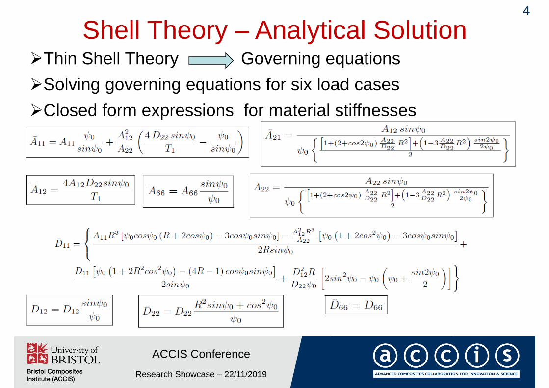
Shell Theory – Analytical Solution
Research Showcase – 22/11/2019
ACCIS Conference
4
Thin Shell Theory Governing equationsSolving governing equations for six load cases Closed form expressions for material stiffnesses

Validation with FEA
Research Showcase – 22/11/2019
ACCIS Conference
5

Orthotropic strain gradient theory
Research Showcase – 22/11/2019
ACCIS Conference
6
Constitutive law of a thin flat orthotropic plate
Material stiffness
Models comparison - Energy approach
