british aerospace bae 146-200a vh-jjp near meekatharra ... · british aerospace bae 146-200a vh-jjp...
TRANSCRIPT

Department of Transport
Bureau of Air Safety Investigation
INVESTIGATION REPORT
B/925/3042
British Aerospace BAe 146-200A VH-JJPNear Meekatharra, Western Australia
22 March 1992
Released by the Director of the Bureau of Air Safety Investigationunder the provisions of Air Navigation Regulation 283

ii
This report was produced by the Bureau of Air Safety Investigation (BASI), PO Box 967, Civic Square ACT 2608.
The Director of the Bureau authorised the investigation and the publication of this report pursuant to his delegated powersconferred by Air Navigation Regulations 278 and 283 respectively. Readers are advised that the Bureau investigates for thesole purpose of enhancing aviation safety. Consequently, Bureau reports are confined to matters of safety significance andmay be misleading if used for any other purpose.
As BASI believes that safety information is of greatest value if it is passed on for the use of others, copyright restrictions do not apply to material printed in this report. Readers are encouraged to copy or reprint for further distribu-tion, but should acknowledge BASI as the source.
ISBN 0 642 20130 7 February 1994
When the Bureau makes recommendations as a resultof its investigations or research, safety (in accordancewith its charter) is its primary consideration. However,the Bureau fully recognises that the implementation ofrecommendations arising from its investigations will insome cases incur a cost to the industry.
Readers should note that the information in BASI reportsis provided to promote aviation safety: in no case is itintended to imply blame or liability.

iii
CONTENTS
TERMS AND ABBREVIATIONS ... . . . . . . . . . . . . . . . . . . . . . . . . . . . . . . . . . . . . . . . . . . . . . . . . . . . . . . . . . . . . . . . . . . . . . . . . . . . . . . . . . . . . . . . . . . . . . . . . . . . . . . . . . . . . . . . . . . . . . . . . . . . . . . . . . . . . . . . . . . . . . . . . . . . . . . . . . . . . . . . . . . . . . . . . . . . . . . . . . . . . . iv
SYNOPSIS .. . . . . . . . . . . . . . . . . . . . . . . . . . . . . . . . . . . . . . . . . . . . . . . . . . . . . . . . . . . . . . . . . . . . . . . . . . . . . . . . . . . . . . . . . . . . . . . . . . . . . . . . . . . . . . . . . . . . . . . . . . . . . . . . . . . . . . . . . . . . . . . . . . . . . . . . . . . . . . . . . . . . . . . . . . . . . . . . . . . . . . . . . . . . . . . . . . . . . . . . . . . . . . . . . . . . . . . . . . . . . . . . . . . . . . . . . . . . . . . . . . . . . . . . . 1
1. FACTUAL INFORMATION ... . . . . . . . . . . . . . . . . . . . . . . . . . . . . . . . . . . . . . . . . . . . . . . . . . . . . . . . . . . . . . . . . . . . . . . . . . . . . . . . . . . . . . . . . . . . . . . . . . . . . . . . . . . . . . . . . . . . . . . . . . . . . . . . . . . . . . . . . . . . . . . . . . . . . . . . . . . . . . . . . . . . . . . . . . . . . . 1
1.1 History of the flight ... . . . . . . . . . . . . . . . . . . . . . . . . . . . . . . . . . . . . . . . . . . . . . . . . . . . . . . . . . . . . . . . . . . . . . . . . . . . . . . . . . . . . . . . . . . . . . . . . . . . . . . . . . . . . . . . . . . . . . . . . . . . . . . . . . . . . . . . . . . . . . . . . . . . . . . . . . . . . . . . . . . . . . . . . . . . 1
1.2 Injuries to persons .. . . . . . . . . . . . . . . . . . . . . . . . . . . . . . . . . . . . . . . . . . . . . . . . . . . . . . . . . . . . . . . . . . . . . . . . . . . . . . . . . . . . . . . . . . . . . . . . . . . . . . . . . . . . . . . . . . . . . . . . . . . . . . . . . . . . . . . . . . . . . . . . . . . . . . . . . . . . . . . . . . . . . . . . . . . . . . . . . . . . 3
1.3 Damage to aircraft .. . . . . . . . . . . . . . . . . . . . . . . . . . . . . . . . . . . . . . . . . . . . . . . . . . . . . . . . . . . . . . . . . . . . . . . . . . . . . . . . . . . . . . . . . . . . . . . . . . . . . . . . . . . . . . . . . . . . . . . . . . . . . . . . . . . . . . . . . . . . . . . . . . . . . . . . . . . . . . . . . . . . . . . . . . . . . . . . . . . . 3
1.4 Other damage .. . . . . . . . . . . . . . . . . . . . . . . . . . . . . . . . . . . . . . . . . . . . . . . . . . . . . . . . . . . . . . . . . . . . . . . . . . . . . . . . . . . . . . . . . . . . . . . . . . . . . . . . . . . . . . . . . . . . . . . . . . . . . . . . . . . . . . . . . . . . . . . . . . . . . . . . . . . . . . . . . . . . . . . . . . . . . . . . . . . . . . . . . . . . . . . . . . 4
1.5 Personnel information .. . . . . . . . . . . . . . . . . . . . . . . . . . . . . . . . . . . . . . . . . . . . . . . . . . . . . . . . . . . . . . . . . . . . . . . . . . . . . . . . . . . . . . . . . . . . . . . . . . . . . . . . . . . . . . . . . . . . . . . . . . . . . . . . . . . . . . . . . . . . . . . . . . . . . . . . . . . . . . . . . . . . . . . . 4
1.6 Aircraft information .. . . . . . . . . . . . . . . . . . . . . . . . . . . . . . . . . . . . . . . . . . . . . . . . . . . . . . . . . . . . . . . . . . . . . . . . . . . . . . . . . . . . . . . . . . . . . . . . . . . . . . . . . . . . . . . . . . . . . . . . . . . . . . . . . . . . . . . . . . . . . . . . . . . . . . . . . . . . . . . . . . . . . . . . . . . . . . . 4
1.7 Meteorological information .. . . . . . . . . . . . . . . . . . . . . . . . . . . . . . . . . . . . . . . . . . . . . . . . . . . . . . . . . . . . . . . . . . . . . . . . . . . . . . . . . . . . . . . . . . . . . . . . . . . . . . . . . . . . . . . . . . . . . . . . . . . . . . . . . . . . . . . . . . . . . . . . . . . . . . . . 4
1.8 Aids to navigation .. . . . . . . . . . . . . . . . . . . . . . . . . . . . . . . . . . . . . . . . . . . . . . . . . . . . . . . . . . . . . . . . . . . . . . . . . . . . . . . . . . . . . . . . . . . . . . . . . . . . . . . . . . . . . . . . . . . . . . . . . . . . . . . . . . . . . . . . . . . . . . . . . . . . . . . . . . . . . . . . . . . . . . . . . . . . . . . . . . . . . 5
1.9 Communications .. . . . . . . . . . . . . . . . . . . . . . . . . . . . . . . . . . . . . . . . . . . . . . . . . . . . . . . . . . . . . . . . . . . . . . . . . . . . . . . . . . . . . . . . . . . . . . . . . . . . . . . . . . . . . . . . . . . . . . . . . . . . . . . . . . . . . . . . . . . . . . . . . . . . . . . . . . . . . . . . . . . . . . . . . . . . . . . . . . . . . . . . 5
1.10 Aerodrome information .. . . . . . . . . . . . . . . . . . . . . . . . . . . . . . . . . . . . . . . . . . . . . . . . . . . . . . . . . . . . . . . . . . . . . . . . . . . . . . . . . . . . . . . . . . . . . . . . . . . . . . . . . . . . . . . . . . . . . . . . . . . . . . . . . . . . . . . . . . . . . . . . . . . . . . . . . . . . . . . . . . . 5
1.11 Flight recorders .. . . . . . . . . . . . . . . . . . . . . . . . . . . . . . . . . . . . . . . . . . . . . . . . . . . . . . . . . . . . . . . . . . . . . . . . . . . . . . . . . . . . . . . . . . . . . . . . . . . . . . . . . . . . . . . . . . . . . . . . . . . . . . . . . . . . . . . . . . . . . . . . . . . . . . . . . . . . . . . . . . . . . . . . . . . . . . . . . . . . . . . . . . . . . . 5
1.11.1 Digital flight data recorder .. . . . . . . . . . . . . . . . . . . . . . . . . . . . . . . . . . . . . . . . . . . . . . . . . . . . . . . . . . . . . . . . . . . . . . . . . . . . . . . . . . . . . . . . . . . . . . . . . . . . . . . . . . . . . . . . . . . . . . . . . . . . . . 5
1.11.2 Cockpit voice recorder .. . . . . . . . . . . . . . . . . . . . . . . . . . . . . . . . . . . . . . . . . . . . . . . . . . . . . . . . . . . . . . . . . . . . . . . . . . . . . . . . . . . . . . . . . . . . . . . . . . . . . . . . . . . . . . . . . . . . . . . . . . . . . . . . . . . . . . . . . . . 5
1.11.3 Engine health monitoring system ... . . . . . . . . . . . . . . . . . . . . . . . . . . . . . . . . . . . . . . . . . . . . . . . . . . . . . . . . . . . . . . . . . . . . . . . . . . . . . . . . . . . . . . . . . . . . . . . . . . . . . . . . 5
1.12 Wreckage and impact information ... . . . . . . . . . . . . . . . . . . . . . . . . . . . . . . . . . . . . . . . . . . . . . . . . . . . . . . . . . . . . . . . . . . . . . . . . . . . . . . . . . . . . . . . . . . . . . . . . . . . . . . . . . . . . . . . . . . . . . . . . . . . 5
1.13 Medical and pathological information ... . . . . . . . . . . . . . . . . . . . . . . . . . . . . . . . . . . . . . . . . . . . . . . . . . . . . . . . . . . . . . . . . . . . . . . . . . . . . . . . . . . . . . . . . . . . . . . . . . . . . . . . . . . . . . . . . . 5
1.14 Fire .. . . . . . . . . . . . . . . . . . . . . . . . . . . . . . . . . . . . . . . . . . . . . . . . . . . . . . . . . . . . . . . . . . . . . . . . . . . . . . . . . . . . . . . . . . . . . . . . . . . . . . . . . . . . . . . . . . . . . . . . . . . . . . . . . . . . . . . . . . . . . . . . . . . . . . . . . . . . . . . . . . . . . . . . . . . . . . . . . . . . . . . . . . . . . . . . . . . . . . . . . . . . . . . . . . . . . . . . . . . . . . . . . . . 5
1.15 Survival aspects .. . . . . . . . . . . . . . . . . . . . . . . . . . . . . . . . . . . . . . . . . . . . . . . . . . . . . . . . . . . . . . . . . . . . . . . . . . . . . . . . . . . . . . . . . . . . . . . . . . . . . . . . . . . . . . . . . . . . . . . . . . . . . . . . . . . . . . . . . . . . . . . . . . . . . . . . . . . . . . . . . . . . . . . . . . . . . . . . . . . . . . . . . . . . . 6
1.16 Tests and research .. . . . . . . . . . . . . . . . . . . . . . . . . . . . . . . . . . . . . . . . . . . . . . . . . . . . . . . . . . . . . . . . . . . . . . . . . . . . . . . . . . . . . . . . . . . . . . . . . . . . . . . . . . . . . . . . . . . . . . . . . . . . . . . . . . . . . . . . . . . . . . . . . . . . . . . . . . . . . . . . . . . . . . . . . . . . . . . . . . . . . . 6
1.16.1 Bleed-air demand ... . . . . . . . . . . . . . . . . . . . . . . . . . . . . . . . . . . . . . . . . . . . . . . . . . . . . . . . . . . . . . . . . . . . . . . . . . . . . . . . . . . . . . . . . . . . . . . . . . . . . . . . . . . . . . . . . . . . . . . . . . . . . . . . . . . . . . . . . . . . . . . . . . . . 6
1.16.2 Fuel control unit calibration ... . . . . . . . . . . . . . . . . . . . . . . . . . . . . . . . . . . . . . . . . . . . . . . . . . . . . . . . . . . . . . . . . . . . . . . . . . . . . . . . . . . . . . . . . . . . . . . . . . . . . . . . . . . . . . . . . . . . . . . . 7
1.17 Additional information .. . . . . . . . . . . . . . . . . . . . . . . . . . . . . . . . . . . . . . . . . . . . . . . . . . . . . . . . . . . . . . . . . . . . . . . . . . . . . . . . . . . . . . . . . . . . . . . . . . . . . . . . . . . . . . . . . . . . . . . . . . . . . . . . . . . . . . . . . . . . . . . . . . . . . . . . . . . . . . . . . . . . . . 7
1.17.1 Engine aspects ... . . . . . . . . . . . . . . . . . . . . . . . . . . . . . . . . . . . . . . . . . . . . . . . . . . . . . . . . . . . . . . . . . . . . . . . . . . . . . . . . . . . . . . . . . . . . . . . . . . . . . . . . . . . . . . . . . . . . . . . . . . . . . . . . . . . . . . . . . . . . . . . . . . . . . . . . . . . . . . 7
1.17.2 Other aspects ... . . . . . . . . . . . . . . . . . . . . . . . . . . . . . . . . . . . . . . . . . . . . . . . . . . . . . . . . . . . . . . . . . . . . . . . . . . . . . . . . . . . . . . . . . . . . . . . . . . . . . . . . . . . . . . . . . . . . . . . . . . . . . . . . . . . . . . . . . . . . . . . . . . . . . . . . . . . . . . . . . 8
2. ANALYSIS .. . . . . . . . . . . . . . . . . . . . . . . . . . . . . . . . . . . . . . . . . . . . . . . . . . . . . . . . . . . . . . . . . . . . . . . . . . . . . . . . . . . . . . . . . . . . . . . . . . . . . . . . . . . . . . . . . . . . . . . . . . . . . . . . . . . . . . . . . . . . . . . . . . . . . . . . . . . . . . . . . . . . . . . . . . . . . . . . . . . . . . . . . . . . . . . . . . . . . . . . . . . . . . . . . . . . . . . . . . . . . . . . . . . 11
2.1 The roll-back .............................................................................................................................................................................................................................. 11
2.2 Cockpit crew actions ... . . . . . . . . . . . . . . . . . . . . . . . . . . . . . . . . . . . . . . . . . . . . . . . . . . . . . . . . . . . . . . . . . . . . . . . . . . . . . . . . . . . . . . . . . . . . . . . . . . . . . . . . . . . . . . . . . . . . . . . . . . . . . . . . . . . . . . . . . . . . . . . . . . . . . . . . . . . . . . . . . . . . . 12
2.3 Use of engine anti-ice ... . . . . . . . . . . . . . . . . . . . . . . . . . . . . . . . . . . . . . . . . . . . . . . . . . . . . . . . . . . . . . . . . . . . . . . . . . . . . . . . . . . . . . . . . . . . . . . . . . . . . . . . . . . . . . . . . . . . . . . . . . . . . . . . . . . . . . . . . . . . . . . . . . . . . . . . . . . . . . . . . . . 12
2.4 Cabin safety aspects ... . . . . . . . . . . . . . . . . . . . . . . . . . . . . . . . . . . . . . . . . . . . . . . . . . . . . . . . . . . . . . . . . . . . . . . . . . . . . . . . . . . . . . . . . . . . . . . . . . . . . . . . . . . . . . . . . . . . . . . . . . . . . . . . . . . . . . . . . . . . . . . . . . . . . . . . . . . . . . . . . . . . . . . . . 13
3. CONCLUSIONS .. . . . . . . . . . . . . . . . . . . . . . . . . . . . . . . . . . . . . . . . . . . . . . . . . . . . . . . . . . . . . . . . . . . . . . . . . . . . . . . . . . . . . . . . . . . . . . . . . . . . . . . . . . . . . . . . . . . . . . . . . . . . . . . . . . . . . . . . . . . . . . . . . . . . . . . . . . . . . . . . . . . . . . . . . . . . . . . . . . . . . . . . . . . . . . . . . . . . . . . . . . . . . . . 14
3.1 Findings .. . . . . . . . . . . . . . . . . . . . . . . . . . . . . . . . . . . . . . . . . . . . . . . . . . . . . . . . . . . . . . . . . . . . . . . . . . . . . . . . . . . . . . . . . . . . . . . . . . . . . . . . . . . . . . . . . . . . . . . . . . . . . . . . . . . . . . . . . . . . . . . . . . . . . . . . . . . . . . . . . . . . . . . . . . . . . . . . . . . . . . . . . . . . . . . . . . . . . . . . . . . . . . . . . 14
3.2 Significant factors .. . . . . . . . . . . . . . . . . . . . . . . . . . . . . . . . . . . . . . . . . . . . . . . . . . . . . . . . . . . . . . . . . . . . . . . . . . . . . . . . . . . . . . . . . . . . . . . . . . . . . . . . . . . . . . . . . . . . . . . . . . . . . . . . . . . . . . . . . . . . . . . . . . . . . . . . . . . . . . . . . . . . . . . . . . . . . . . . . . . . 14
4. SAFETY ACTION ... . . . . . . . . . . . . . . . . . . . . . . . . . . . . . . . . . . . . . . . . . . . . . . . . . . . . . . . . . . . . . . . . . . . . . . . . . . . . . . . . . . . . . . . . . . . . . . . . . . . . . . . . . . . . . . . . . . . . . . . . . . . . . . . . . . . . . . . . . . . . . . . . . . . . . . . . . . . . . . . . . . . . . . . . . . . . . . . . . . . . . . . . . . . . . . . . . . . . . . . . . . . 16
4.1 Safety actions taken ... . . . . . . . . . . . . . . . . . . . . . . . . . . . . . . . . . . . . . . . . . . . . . . . . . . . . . . . . . . . . . . . . . . . . . . . . . . . . . . . . . . . . . . . . . . . . . . . . . . . . . . . . . . . . . . . . . . . . . . . . . . . . . . . . . . . . . . . . . . . . . . . . . . . . . . . . . . . . . . . . . . . . . . . . . . . . . . 16
4.2 Safety Advisory Notices .. . . . . . . . . . . . . . . . . . . . . . . . . . . . . . . . . . . . . . . . . . . . . . . . . . . . . . . . . . . . . . . . . . . . . . . . . . . . . . . . . . . . . . . . . . . . . . . . . . . . . . . . . . . . . . . . . . . . . . . . . . . . . . . . . . . . . . . . . . . . . . . . . . . . . . . . . . . . . . . . . . . . 16
4.3 Final recommendations .. . . . . . . . . . . . . . . . . . . . . . . . . . . . . . . . . . . . . . . . . . . . . . . . . . . . . . . . . . . . . . . . . . . . . . . . . . . . . . . . . . . . . . . . . . . . . . . . . . . . . . . . . . . . . . . . . . . . . . . . . . . . . . . . . . . . . . . . . . . . . . . . . . . . . . . . . . . . . . . . . . . . 16
Appendix 1 Meteorological conditions associated with BAe 146 incidenton 22 March 1992 northwest of Meekatharra WA ... . . . . . . . . . . . . . . . . . . . . . . . . . . . . . . . . . . . . . . . . . . . . . . . . . . . . . . . . . . . . . . . . . . . . . . . . . . . . . . . . . . 19
Appendix 2 Flight recorder data plot .. . . . . . . . . . . . . . . . . . . . . . . . . . . . . . . . . . . . . . . . . . . . . . . . . . . . . . . . . . . . . . . . . . . . . . . . . . . . . . . . . . . . . . . . . . . . . . . . . . . . . . . . . . . . . . . . . . . . . . . . . . . . . . . . . . . . . . . . . . . . . . . . . . . . . . . . . . . . . . . . . . 31
Appendix 3 Notice to aircrew: Operational Notice No. 25 ... . . . . . . . . . . . . . . . . . . . . . . . . . . . . . . . . . . . . . . . . . . . . . . . . . . . . . . . . . . . . . . . . . . . . . . . . . . . . . . . . . . . . . . . . . . . . . . . 32
TERMS AND ABBREVIATIONS
AIREP Air Report (by a pilot detailing actual weather conditions)
ATPL Airline Transport Pilot Licence
CAA Civil Aviation Authority
CAO Civil Aviation Order
ECS Environmental Control System
ELC Engine Life Computer
FCU Fuel Control Unit
FL Flight Level
IAS Indicated Air Speed
ISA International Standard Atmosphere
M Mach
IMN Indicated Mach Number
MCT Maximum Continuous Thrust
N1 Engine Fan Speed (%)
N2 High Pressure Rotor Speed (%)
OAT Outside Air Temperature
PA Public Address
TGT Turbine Gas Temperature (°C)
TMS Thrust Modulation System
PAN A radiotelephony signal, indicating that an aircraft’s safety is threatened however,immediate assistance is not required.
Mayday A radiotelephony signal, indicating that an aircraft is threatened by serious and/orimminent danger and requires immediate assistance.
All times are Australian Western Standard Time (Co-ordinated Universal Time + 8 hours)unless otherwise stated.
iv

1
SYNOPSIS
The aircraft was on a scheduled domestic passenger service flight from Karratha to Perthat Flight Level 310 (31,000 ft). As the aircraft entered cloud while diverting around a largethunderstorm, there was a sudden and significant rise in the outside air temperature. Ashort time later, all four engines progressively lost power and the aircraft was unable tomaintain altitude. During the next 17 minutes, numerous attempts to restore engine powerwere made without success until, approaching 10,000 ft altitude, normal engine operationwas regained. The aircraft diverted to Meekatharra where a normal landing wascompleted.
The investigation determined that during high altitude cruise, the aircraft entered an areaof moist air significantly warmer than the surrounding air. This resulted in a need to selectengine and airframe anti-ice which in turn placed high bleed air demand on the engines.Under these conditions the fuel control units were unable to schedule sufficient fuel to theengines, thereby causing them to lose power, a phenomenon known as ‘roll-back’.
1. FACTUAL INFORMATION
1.1 History of the flight
The aircraft departed Karratha, WA, at 2005 hours on 22 March 1992. There were 51passengers, two pilots and three cabin crew on board.
Takeoff and departure were normal and the aircraft was climbed towards the planned cruiselevel of FL 280. Approaching this level, the crew decided to continue the climb to FL 310(maximum approved altitude) to avoid thunderstorms ahead. Because of the anticipated lowertemperature at FL 310, engine icing was not expected. Cruise was established at FL 310 and thecrew set the TMS to TGT mode with 800°C selected as reference.
At 2030 hours the aircraft reported maintaining FL 310. Included with this report was anAIREP indicating that the OAT at this level was -39°C and that the aircraft was cruising at anindicated Mach number of 0.67M. At 2033 hours, the crew requested clearance to divert up to20 NM right of track to avoid a thunderstorm cell. This placed the aircraft about 30 NM fromthe thunderstorm cell. As the aircraft entered cloud tops abeam the cell, the ice detector lightilluminated on the master warning system panel, and the crew noticed that the OAT had risento above -35°C and was still rising. In response to this, anti-ice was selected ON for all enginesand the crew visually checked for ice accumulation on the wings. Deciding that ice may havebeen present, the crew ensured that the TGT was at 800°C, that the engine fan (N1) RPMindications were between 90% and 92% and the engine core (N2) RPM indications were92–93%, and then selected wing anti-ice ON. After 2 minutes the wing anti-ice was turned offand the tail anti-ice was selected ON. The IMN was noted at 0.62M and still decreasing.
At 2040 hours the crew, suspecting airframe icing, requested a descent to FL 290, at the sametime selecting a TGT of 840°C and both wing and tail anti-icing ON. With the aircraftapproaching FL 290 with 1,000 ft/min rate of descent and holding an IAS of 220 kts, the OATreading was -22°C.
At 2043 hours, the crew requested a further descent to FL 270 and noted that the engine N1RPM indications were decreasing towards 75%, although the N2 indications were unchanged.Engine ignition was selected ON. Maximum continuous thrust was selected on the TMS andthe wing and tail anti-icing selected OFF.

2
At 2046 hours, the crew requested a descent to FL 250. At about that time the autopilotdisengaged and the IAS decreased to 200 kts with a rate of descent of 1,500 ft/min. The TMSwas disconnected when the intake low pressure warning illuminated. By then the N1 RPMgauges indicated about 60% and the crew perceived that the no. 4 engine appeared ready toflame out.
At 2047 hours, the captain retarded the no. 1 engine thrust lever to assess the engine-idleparameters. They were well below normal flight-idle indications and deteriorating rapidly, sothe lever was moved forward to match the position of the other levers. The no. 4 engine wasshut down by the crew. The other thrust levers were fully advanced with no obvious effect onN1 RPM indications. The engine parameters at this time, as later obtained from the ELCrecording, were as follows:
No.1 No. 2 No. 3 No. 4
N1 RPM(%) 61 59.6 70.9 26.5
N2 RPM(%) 88.1 90.7 89.9 37.8
TGT (°C) 865 860 855 664
Fuel flow (lb/hour) 292 279 365 0
Engine anti-ice on on on off
Engine bleed air on on on on
Air conditioning packs 1 and 2 were both on.
At 2047.24 hours, the crew transmitted a PAN call, advising:
• a loss of power on all engines;
• that altitude could not be maintained;
• that they were descending through FL 250; and
• that they were setting course for Carnarvon.A short time later, the destination was changed to Meekatharra, which was slightly closer.
At 2048.30 hours, both engine-driven generators were off-line. The no. 4 engine was restartedand the ELC data was then as follows:
No.1 No. 2 No. 3 No. 4
N1 RPM(%) 52.2 51.0 62.5 24.8
N2 RPM(%) 85.6 88.4 89.7 30.2
TGT (°C) 864 859 855 693
Fuel flow (lb/hour) 254 244 319 85
Engine anti-ice on on on off
Engine bleed air on on on on
Air conditioning packs 1 and 2 were both on.
At about 2050 hours, the no. 1 engine-driven generator and the hydraulically driven standbygenerator were constantly cycling on and off line, resulting in relay chatter and an unstablepower supply. This required the aircraft to be hand flown using standby flight instruments.During this period, several warning and overhead panel lights illuminated, including the cabinhigh-altitude warning light. The crew noted that the cabin altitude was increasing at the rate ofabout 2,000 ft/min while the aircraft, at an IAS of 200 kts, was descending at about 2,000 ft/min.The crew fitted their oxygen masks and manually deployed passenger oxygen masks.
The purser then reported a burning smell and high temperature in the rear cabin. At about the sametime, light smoke and a burning smell were detected in the cockpit but this quickly dispersed.

3
At 2051.43 hours, the crew transmitted a Mayday call advising that the aircraft was passing FL 190 in an emergency descent, unable to maintain altitude, and heading for Meekatharra.The purser was then briefed to prepare for a forced landing in approximately 12 to 15 minutes.
The crew shut down the nos.1 and 3 engines by placing the relevant thrust levers in the fuel-offposition. The nos. 2 and 4 thrust levers were set well forward but not fully forward; theseengines remained below flight-idle. Generator no. 1 and engine no. 3 hydraulic pump wereselected off, as were the anti-ice and air bleeds for all engines. Flight-idle was then selected fornos.1 and 3 engines and both started but did not accelerate.
At 2053.23 hours, the auxiliary power unit was started and normal electrical power supply wasrestored to the left side of the cockpit. The no. 2 engine oil pressure warning was illuminated atthis time.
The ELC data at 2054.03 hours was as follows:
No.1 No.2 No. 3 No. 4
N1 RPM(%) 24.7 21.7 24.9 24.1
N2 RPM(%) 42.3 28.6 45.0 40.9
TGT (°C) 700 931 741 570
Fuel flow (lb/hour) 83 120 80 90
Engine anti-ice off off off off
Bleed air on on on on
Air conditioning packs 1 and 2—both off
At 2054 hours, as the aircraft descended through FL 160, the no. 1 engine low oil pressurewarning illuminated. At 2054.25 hours, the no. 4 engine low oil pressure light illuminatedwhile a similar indication for no. 3 engine occurred 35 seconds later. ELC data for this periodindicated that the engines were continuing to roll back.
At 2056 hours, the crew shut down nos.1 and 3 engines and then shortly afterwards attemptedto restart them. Both engines did not accelerate past their pre-shutdown condition. As theaircraft was passing FL 120, no. 1 engine accelerated (TGT reached 920°C) and the aircraftyawed. Six seconds later, no. 3 engine accelerated. All indications for these engines were normalless than 1 min later. As the aircraft was levelled at 10,000 ft, nos. 2 and 4 engines acceleratedand were soon operating normally. The remainder of the flight to Meekatharra proceededuneventfully.
1.2 Injuries to persons
There were no injuries to the passengers or crew.
1.3 Damage to aircraft
The TGT limit was exceeded on nos.1 and 2 engines during the occurrence. The exceedence onthe no. 1 engine was minor and caused no damage. However, the no. 2 engine was subjected totemperatures in excess of 20% above the TGT limit for more than 3.5 minutes. A temperatureexceedence of this extent required that the engine be removed for a major inspection. Duringthe inspection, four blades from the first stage high-pressure compressor were found to havesoft foreign object damage consistent with ice ingestion. No other damage was found.
1.4 Other damage
No other damage was reported.
4
1.5 Personnel information
The pilot in command was aged 43 and held an ATPL. He was endorsed to fly BAe 146 aircraftand at the time of the incident had a total flying experience of 11,400 hours, of which over2,000 were on BAe 146 aircraft. In the 30 days prior to the incident, he had flown 70 hours aspilot in command of BAe 146 aircraft. The pilot’s flight proficiency was last checked inNovember 1991, and he had no medical restrictions. The pilot regularly flew the route betweenKarratha and Perth.
The first officer was aged 41 and held an ATPL on which he was endorsed to fly BAe 146aircraft. At the time of the incident he had a total flying experience of 16,096 hours, of which503 were on BAe 146 aircraft as first officer. In the 30 days prior to the incident, the first officerhad flown 77 hours. His flight proficiency was last checked in January 1992 and he had nomedical restrictions. The first officer, because of his extensive general aviation experience in thearea, was familiar with the sector between Karratha and Perth.
1.6 Aircraft information
The aircraft was manufactured in the United Kingdom by British Aerospace in 1985, as a BAe146-200A with Serial No. E2037 and later that year was registered in Australia as VH-JJP.
It had been maintained in accordance with the approved maintenance schedule and the lastmajor scheduled inspection was conducted on 6 November 1991. At the time of the incident,the aircraft had accumulated approximately 19,800 flight hours.
Four Textron Lycoming ALF502R-5 turbo-fan engines were fitted to the aircraft, two mountedunder each wing. The engines were maintained on condition and inspected as part of acontinuous maintenance program.
There was no evidence that the engines, airframe or accessories had any defects or outstandingmaintenance requirements which could have contributed to the incident.
The take-off weight and centre of gravity of the aircraft were within the specified limits.
The aircraft fuel used was aviation turbine fuel (Avtur). There was no evidence ofcontamination in the aircraft fuel system.
1.7 Meteorological information
The general synoptic situation featured a high pressure ridge to the south of Western Australiaand a low pressure system located over the central Kimberley area. Embedded in the broadeasterly airflow between these two pressure centres was a trough running roughly north-souththrough the incident area.
The atmosphere over much of Western Australia was unstable, and, coupled with the highlevels of moisture and triggered by the afternoon heating gave rise to embedded thunderstormswithin a pre-existing middle level cloud mass.
Winds in the area of the incident at FL 310 were north-westerly at 30–40 kts.
A meteorological report, communicated from the aircraft shortly before the commencement ofthe incident, indicated that the OAT was -39°C. At that time, the aircraft was clear of cloud atFL 310.
The Bureau of Meteorology provided an evaluation and analysis of the weather-relatedcircumstances surrounding the incident (see appendix 1).
1.8 Aids to navigation
Not relevant.

1.9 Communications
The aircraft was operating under the control of Perth Air Traffic Control (Sector 2) at the timeof the incident. The automatic voice recording tape of communications between Sector 2 andthe aircraft indicated that satisfactory two-way communications existed during the period ofthe occurrence.
1.10 Aerodrome information
Not relevant.
1.11 Flight recorders
1.11.1 Digital flight data recorder
The aircraft was equipped with a Plessey PV1584J digital flight data acquisition and recordingunit, with the capacity to record the last 25 hours of flight data. The recorder on VH-JJPrecorded 32 continuous engineering parameters and 33 other discrete parameters. Initialexamination of the recording revealed that data for a number of parameters was corrupt. Theaffected parameters included:
• pressure altitude;
• indicated airspeed; and
• N1 RPM for each engine.
Examination of the recorder indicated that there had been a failure of the reference voltage tothe sensors for these parameters. The fault was traced to a voltage regulator. The equipmentmanufacturer reported that this was the only such failure recorded for this type of recorder.Despite the failure, the recording did contain useful data. A plot of selected parameters wasproduced for the period 2030:00 hours to 2103:00 hours, covering the time of this incident(appendix 2).
1.11.2 Cockpit voice recorder
VH-JJP was equipped with a cockpit voice recorder with a recording duration of 30 minutes.Because more than 30 minutes elapsed between power being restored on the engines and theaircraft arriving at Meekatharra, all information pertaining to the occurrence had been over-recorded.
1.11.3 Engine health monitoring system
The aircraft was equipped with an ELC which recorded a data block of engine parameterswhenever an out-of-limit warning occurred. Each block of data covered 21 seconds of engineoperation from 5 seconds before the triggering event to 15 seconds after. Information from anumber of recorded data blocks was included in section 1.1 of this report.
1.12 Wreckage and impact information
Not relevant.
1.13 Medical and pathological information
Not relevant.
1.14 Fire
Four passengers reported what appeared to be a fire from the engines on the left side of theaircraft. Post flight examination did not reveal any evidence of an in-flight fire.
5

6
1.15 Survival aspects
Not relevant.
1.16 Tests and research
1.16.1 Bleed air demand
The ALF502R-5 engine is fitted with an interstage bleed air overboard dump valve which iscontrolled by the FCU and is opened under certain operating conditions to protect the engineagainst compressor surge and/or stall. In addition, the aircraft has a number of systems whichrequire bleed air from the engines. These are:
• outer wing anti-ice (supplied by both engines on the applicable wing);
• inner wing de-ice (supplied by both engines on the applicable wing);
• tailplane anti-ice (supplied by all engines);
• environmental control system (ECS) (supplied by all engines); and,
• engine anti-ice (supplied by the corresponding engine).
It was not possible to positively determine the selection of the ECS. Initial informationindicated it was in the fresh air mode, but later information suggests that it may have been inthe recirculating mode. On this basis, calculations were performed for both cases.
Using data on the bleed air flow rates required by the aircraft and engine systems listed above,comparisons were made of the maximum bleed air drain on the engines under the conditionsexperienced by the aircraft prior to, and after entering, the higher temperature air mass. Thesecomparisons are summarised as follows:
Event Ambient air Bleed air services Bleed air extractiontemperature operating Fresh Recirc.
Prior to OAT rise -33.4°C ECS 3.0% 1.7%(ISA + 11°C)
ECS 5.6% 4.3%plus engine anti-ice
At initial OAT rise -22.4°C ECS 6.1% 4.7%(ISA + 22°C) plus engine anti-ice
ECS 8.21% 6.9%plus engine anti-iceplus outer wing anti-ice
ECS 7.6% 6.2%plus engine anti-iceplus tail anti-ice
When power was -22.4°C ECS 9.1% 7.8% increased (ISA + 22°C) plus engine anti-ice
plus outer wing anti-iceplus tail anti-ice
At maximum -15.4°C ECS 9.6% 8.3%OAT (ISA + 29°C) plus engine anti-ice
plus outer wing anti-iceplus tail anti-ice

The engine installation instructions specified that the maximum bleed air demand for aircraftand engine services should not exceed 8% of total air mass flow through each engine. However,the instructions did permit a total of 9.5% in icing conditions.
The ECS system can be operated in either the fresh air or the recirculating mode. As the abovedata shows, operating in the recirculating mode reduces the bleed air demand on the enginesby about 1.2%.
Note that the above calculations apply only when the engine interstage bleed valves remainclosed. If the bleed valves open, the core engine flow is reduced and the percentage of airextracted increases. Data on the amount of air dumped by the interstage bleed air valves wasnot available.
1.16.2 Fuel control unit calibration
Following the incident, the FCUs were removed from the engines and tested.
All the FCUs were within tolerance at the high RPM point (equivalent to 88.6% N2). The unitsfrom nos. 1, 2 and 3 engines were close to the centre of the tolerance band, but the FCU fromno. 4 engine was near the low fuel flow limit of the band.
At the intermediate RPM point (79.2% N2), the FCU from no. 2 engine was outside the upperlimit of the tolerance band.
At the minimum fuel flow point, the FCUs from nos. 1 and 2 engines were outside the upperlimit of the tolerance band.
1.17 Additional information
1.17.1 Engine aspects
Electrical load
In the immediate lead-up to the occurrence, the cabin crew were operating the galley ovensand other equipment prior to serving a meal. The resultant high electrical load would haveplaced additional mechanical load on those engines fitted with generators (nos. 1 and 4engines).
Factors affecting roll-back
The phenomenon in which aircraft engines lose power as described in section 1.1 is commonlyreferred to as engine ‘roll-back’.
At the time of this occurrence, the factors involved in engine roll-back in BAe 146 aircraft wereunder investigation by the engine and aircraft manufacturers as a result of three earlierincidents. These similar incidents, which occurred overseas, involved roll-backs in one, two,and three engines. However, the VH-JJP occurrence was the first in which all four engines on aBAe 146 aircraft were affected. All incidents occurred at high altitude (28,000 ft or above), athigher than standard temperatures (ISA + 10°C or greater), and in moist conditions wherebleed air was being drawn from the engines for airframe and/or engine anti-icing.
The basic causes of roll-back are as follows:
• In the low air densities at high altitudes, the aircraft engines must be operated atrelatively high power settings for the necessary thrust to be developed. Loading on theengines is increased by higher than standard OATs, by power demands from the enginefor services such as pumps and generators, and by high bleed air demand to the ECS oranti-ice systems. Under such conditions, the FCUs will schedule a relatively high fuel air
7

ratio and the TGTs will, correspondingly, be towards the upper limit.
• As the FCU increases fuel flow to the engine in response to higher loads, a point isreached where the interstage bleed valves are triggered open to maintain smooth airflowthrough the compressor, thereby dumping part of the engine core air overboard andreducing the power output of the engine. The FCU responds to this by increasing thefuel flow to the engine until the acceleration limit is reached after which no additionalfuel can be supplied.
• Before this limit is reached, the high pressure turbine will have been extracting anincreasing proportion of the power available from the (reduced) core flow to meet theneeds of the compressor (and other power demands), thereby reducing the poweravailable to drive the low-pressure turbine which drives the fan. Hence, fan (N1) RPMwill begin to decrease before engine core (N2) RPM shows any significant fall. As N2 RPMdecreases, core air flow falls as does the fuel-air ratio via the FCU. Furthermore, bleedair represents an increasing percentage of core flow as core air flow falls. Thus, theprocess becomes self sustaining unless action is taken to relieve the power extractionfrom the engines.
Advice on engine roll-back to aircraft crews
The possibility of engine roll-back during high altitude cruise in high ambient temperatures,with engine and airframe anti-ice on, was addressed by the aircraft manufacturer in severalNotices to Aircrew prior to the VH-JJP occurrence. Details of these notices were as follows:
1. Operational Notice to Aircrew OP 17 was issued in October 1987 and titled EngineN1/N2 mismatch with anti-ice selected.
2. Operational Notice to Aircrew OP 22 was issued in May 1991 and replaced OP 17. It was titled Engine N1/N2/TGT abnormal relationship with airframe anti-icing selectedON.
3. Operational Notice to Aircrew OP 25 was issued in November 1991 and replacedOP 22. It was titled Engine bleed band open with airframe outer wing and tail anti-ice
on above 25,000 ft (appendix 3).
The crew of VH-JJP had received OP 25 during the week before the incident. However, theydid not initiate the actions listed in OP 25 because they did not equate the symptoms withwhich they were confronted with the description in OP 25.
Company procedures
Company procedures required the use of engine anti-ice if any free moisture was present and ifthe OAT was warmer than -35°C. This compares with the minimum temperature for theexistence of supercooled water, as established by laboratory tests, of -40°C.
1.17.2 Other aspects
Crew teamwork
When the cabin crew detected a burning smell in the aircraft cabin, the information wasimmediately passed to the cockpit. Four passengers seated on the left side of the cabin reportedseeing signs of fire from the left engine(s) in the form of flames and engines ‘glowing’. At leastone passenger reported this observation to a cabin crew member who did not convey it to thecockpit as she thought the cockpit crew were already aware of the problem.
8

9
Crew use of oxygen masks
With the pilots wearing oxygen masks, intra-cockpit communications are by way ofmicrophones fitted within the masks and the cockpit overhead speakers. The aircraft electricalsystem is so arranged that, when the generators are off-line and the aircraft batteries arepowering essential electrics, the speaker on the first officer’s side of the cockpit is deactivated,thereby affecting the quality of intra-cockpit communications.
The purser’s oxygen mask was not fitted with a microphone, so to make PA announcements tothe cabin, he had to remove the mask. Civil Aviation Order 20.11 appendix IV requires crewmembers to have a theoretical knowledge of altitude and the effects of hypoxia. However,pursers do not receive practical training in the effects of hypoxia and, in this instance, thepurser reported that he was not familiar with the physical manifestations of the onset of thiscondition.
Flight attendant seating—view into cabin
The flight attendant seating positions were:
• purser adjacent to the left forward door facing forwards;
• position two in the cabin behind the last rear seat on the left side; and,
• position three adjacent to the left rear door, facing rearwards.
This arrangement meant that only the attendant in position two could see the passenger cabinwhen seated. This is also the only attendant position without a communications panel.
Regulations do not require the cabin to be under observation by a flight attendant with acommunications panel. However, the cabin crew need to able to see events in the cabin so thatthey can pass relevant information to the cockpit.
Facilities exist to install a mirror in the cabin to enable the purser to view most of the cabin,and all aircraft from this company were delivered with mirrors installed at front and rearvestibules. Some BAe 146 aircraft operated by the company which were inspected during theinvestigation, did have mirrors fitted, but VH-JJP did not, so the purser could not monitor thepassengers whilst seated at his station during the incident sequence.
Cabin equipment/procedures
Interviews with the cabin crew highlighted the following issues:
1. During the descent, the cabin lights flickered on and off and chimes soundedrepeatedly. The cabin crew reported that this alarmed the passengers and made theirtask of reading the passenger safety checklist more difficult because of insufficient light.
2. The cabin crew reported difficulty in reading the emergency checklist pages whichwere printed in black on grey paper. The purser reported that he used the glow of theemergency exit lighting to read the cabin announcements. Torches were provided forthe cabin crew but could not be used when both hands were required to hold anemergency procedures booklet or to support the crew member. The aircraft was notequipped with an independently powered emergency cabin lighting system for use insuch circumstances.
3. Aisle seated passengers on the three-abreast seating side of the aircraft experienceddifficulties in fitting their oxygen masks due to the limited length of the oxygen tubes.One passenger pulled the mask from its fitting. In addition, the hoses were not longenough for the passengers to practice the brace position while wearing their oxygenmasks.

10
4. The flight attendant at position three experienced difficulty in hearing the speakerand watching for the call light during the incident. This was because of the location ofthe speaker and call light for that position.
5. The purser’s PA announcement instructed passengers to remove certain articles(including ‘glasses’—presumably spectacles) and to stow them in the seat pocket. Atthe end of the announcement the passengers were then instructed to study the safetycard in the seat pocket. This would not have been possible for a passenger requiringreading spectacles.
Passenger questionnaire
A cabin-safety questionnaire was sent to 47 of the passengers on the aircraft. Replies werereceived from 34 passengers. Significant responses were as follows:
1. All respondents reported that they knew the location of the nearest emergency exit,and had obtained this information from the pre-flight briefing or, because they werefrequent air travellers, already knew the location of exits. One respondent stated thatemergency exits were always half-way along the cabin. In the BAe 146 aircraft thereare no centre-cabin exits.
2. Only three respondents stated that they neither watched nor listened to the pre-flightbriefing. Of the remainder, 24 reported that they listened to and watched the briefing;
3. All except one of the respondents reported that they understood the emergencybriefing from the flight attendant at the time of the incident;
4. Twelve respondents read the safety briefing card prior to the incident;
5. Six respondents found difficulty in adopting the brace position in response to thepurser’s instructions because their head contacted the back of the seat in front.
6. Most respondents commented favourably on the cabin crew’s performance and theirconcern for the passengers’ safety. However, some felt that the airline should haveoffered some form of stress de-briefing after the event.
Visual wing-ice inspection
The cockpit crew reported being unable to visually confirm the extent of wing icing becausethe colour of the wing leading edge offered no contrast against which ice might be seen.
Operations Manual inaccuracies
During the course of the investigation, it was discovered that the manufacturer’s OperationsManual supplied to and used by the company for the BAe 146 aircraft, contained incorrectinformation regarding the way in which bleed air is distributed to the wing anti-ice system.The company used the information in that Operations Manual, for systems training of aircrewand engineering personnel.
The same incorrect information was found in the BAe 146 Series 100/200 Type Record(description of the aircraft and its build standard at the time of certification).

11
2. ANALYSIS
2.1 The roll-back
The investigation revealed that there were no significant material or calibration deficiencies ineither the aircraft or the engines which would have contributed to the occurrence. The roll-backoccurred under unusual, but not extreme, environmental conditions when the aircraft wascruising at its maximum approved altitude. When anti-ice was selected in response to theairframe ice warning, no. 4 engine could not support the additional bleed air drain andcommenced to roll back. This was followed by the other three engines.
ELC data indicated that the initial (no. 4 engine) roll-back probably began 2 to 3 minutes afterthe sudden rise in OAT and after the crew had activated the outer wing anti-ice system.Consequently, five factors can be correlated with the commencement of no. 4 engine roll-back.These were:
1. a pre-existing bleed air extraction for ECS and engine anti-ice;2. a decrease in air mass flow through the engine due to lower air density at the
increased temperature;3. aircraft entry into an area of icing;4. an increase in bleed air extraction following the selection by the crew of outer wing
anti-ice; and5. placement of a high mechanical load on nos. 1 and 4 engines by the high electrical
demand at the time.
Calculations showed that the combined effect of the temperature increase and the selection ofengine and airframe anti-ice increased the bleed air extraction from 3% to 9.6% with ECS infresh air mode (1.7% to 8.3% with ECS in RECIRC) at the point of maximum OAT. Thesehigher figures are close to, or slightly above, the maximum bleed air extraction of 8% (9.5% inicing conditions) stipulated by the manufacturer.
Prior to the incident, the TMS was engaged in the TGT mode with 800°C initially selected.This was later increased to 840°C, then MCT, and finally the TMS was deselected. The use ofTMS would have inhibited the engine FCUs from initially scheduling maximum fuel flow andmay have accelerated the initial stages of the roll-back. However, after the MCT selection, theuse of TMS would have had no influence on subsequent events.
What direct effect, if any, icing may have had on the initiation of the roll-back could not bedetermined. Nevertheless, later in the descent, after the engines had not responded to thecrew’s initial actions, icing of the engine core is likely to have prolonged the roll-back.
The reason for no. 4 engine rolling back first is explained by the FCU calibration figures whichshow that, at the high RPM point, the FCU from no. 4 engine was near the low limit of thetolerance band while the other three engines’ FCUs were close to the centre of the band.Consequently, the maximum fuel flow available to no. 4 engine was less than that available tothe other engines.
ELC data shows that the N2 RPM for all engines remained steady until the N1s had decreasedto below about 60% when the N2s also began falling. While the N2s remained constant, theTGTs were maintained at the MCT value by the FCUs. After the N2s fell below about 88%, theTGTs also began to decrease, indicating a lower fuel-air ratio. These trends in TGT indicatedcorrect operation of the FCUs. The engines continued to roll back until a sub-idle conditionwas reached.

12
Recovery from the roll-back did not commence until the aircraft reached the forecast freezinglevel. This is consistent with airflow through the engine cores being degraded by a build-up ofice. The failure of the engines to recover or stabilise after the crew actions of shutting down andrestarting engines, adjusting thrust levers, and selecting all engine and airframe anti-ice, andthe ECS system off, is also consistent with ice already having formed within the compressorand affecting the airflow through the engine cores. Icing of the core under a low power or sub-idle condition was likely because any bleed air that might have been available for anti-ice usewould have been at too low a temperature to have had any useful effect.
2.2 Cockpit crew actions
The flight crew were aware of Operational Notice 25 but because they did not associate thecockpit indications with the information contained in Operational Notice 25, they used alogical and knowledge-based approach in attempting to regain normal engine operation. Theydid not remove all bleed air and mechanical load from the engines until the later stages of theoccurrence, even though post-event analysis indicates that early implementation of theseactions may have aided in the recovery from the initial stages of the roll-back development.When the crew did initiate the actions, it is likely that they were ineffective because, by thattime, the engines were affected by ice within the compressor sections. Under thesecircumstances, there was little the crew could do until the ice had melted and the compressorairflow had returned to normal.
There were shortcomings in Operational Notice 25, namely:
1. It did not address the possibility that more than one engine could be affected.
2. It did not mention the possibility of further reduction or possible roll-back to a sub-idle condition if the crew did not take prompt action.
3. It did not address the possibility of the affected engine failing to respond to therecommended corrective action.
4. It suffered from technical wording that did not emphasise factors which would havebeen of prime interest to the crew in recognising the initial stages of roll-back.
The initial symptoms as described by the crew were not aligned with those set out inOperational Notice 25. The increase in OAT followed by the airframe ice warning and thenthe deterioration in aircraft performance were consistent with airframe icing. The engine N1RPM indication remained steady until the aircraft had descended to about FL 290. When thecrew saw the engine N1 RPM indications approaching 75%, the wing and tail de-icing wasselected off. However, both ECS packs and engine anti-ice and bleed air were left on,probably prolonging the roll-back. The actions of the crew, therefore, were partially in linewith those listed in Operational Notice 25 and were consistent with good cockpit resourcemanagement given the deficiencies in the Operational Notice and the initial indications ofthe problem.
The inaccuracies in the manufacturer’s Operations Manual and subsequent training given tothe flight crew based on this inaccurate information, had no bearing on the development of theroll-back incident. The crew’s actions were based on their general understanding of the bleeddemand and not on the specifics of the distribution system as described in the Manual.
2.3 Use of engine anti-ice
The company procedure of using engine anti-ice if any free moisture is present and the OAT isabove -35°C (compared to the minimum temperature for supercooled water of -40°C) doesnot make allowance for the possibility of warm/moist air encounters such as occurred in this

13
instance. A change in the temperature above which engine anti-ice is used to -40°C wouldprovide a greater buffer in the event of a warm/moist air encounter.
2.4 Cabin safety aspects
The cabin crew performed their duties in accordance with training standards, despite beingplaced in an unforeseen and unrehearsed set of circumstances. However, during theinvestigation, a number of deficiencies were identified which impinge on cabin safety. Theseare mentioned in section 1.17.2 and, while they in no way related to the basic factors leadingto this incident, they could affect the safety of the passengers and cabin crew in certaincircumstances.
Some of these deficiencies should have been discovered or eliminated during certificationand/or training. That they were present indicated that both certification and training processeswere not structured to highlight adequately some safety problem areas. Safetyrecommendations regarding these deficiencies are made at the end of this report.

14
3. CONCLUSIONS
3.1 Findings
1. The pilots were qualified and medically fit for the flight.
2. The aircraft was serviceable and its weight and centre of gravity were within limits.
3. While passing about 30 NM abeam a thunderstorm at FL 310, the aircraft encountered apool of moist air which was significantly warmer than the surrounding air, prompting thecrew to activate the engine and aircraft anti-ice systems.
4. The combined effect of the temperature increase and bleed air demand for the anti-icesystems caused the bleed air demand on the engines to be close to or slightly above themaximum stipulated by the engine manufacturer. The response of the FCUs was initiallyinhibited by operating the TMS in the TGT mode.
5. The interstage bleed opened and the combination of airframe and engine anti-ice bleedand compressor interstage bleed resulted in a fuel flow demand greater than the FCU couldprovide.
6. No. 4 engine was the first to roll back, followed shortly thereafter by the other threeengines.
7. The effect, if any, of icing on the initiation of the roll-back could not be determined.
8. During the descent, when the engines did not respond to the crew’s attempts to restorepower, icing of the engine cores probably prolonged the roll-back.
9. All engines returned to normal operation after the aircraft descended below the freezinglevel (about 13,500 ft).
10. There were deficiencies in Operational Notice 25 issued by the aircraft manufacturer whichaddressed the possibility of engine roll-back during high altitude cruise in high ambienttemperatures, with engine and airframe anti-ice on.
11. The actions of the cockpit crew were in accordance with the information available to them
12. Information concerning possible signs of fire in the engines on the left side of the aircraftwas not passed from the cabin to the cockpit crew.
13. The speaker on the first officer’s side of the cockpit was deactivated when the aircraftbatteries were powering the essential electrics, degrading the quality of intra-cockpitcommunications.
14. No microphone was fitted to the purser’s oxygen mask to allow the purser to make PAannouncements while wearing the mask.
15. Emergency procedures checklists for the cabin crew were difficult to read in reduced lightconditions.
16. The only flight attendant seating position offering a view into the passenger cabin was notequipped with a communications panel.
17. Aisle passengers on the three-abreast seating side of the aircraft had difficulty fitting theiroxygen masks due to the limited length of the tube to the mask.

15
3.2 Significant factors
1. During high altitude cruise, the aircraft encountered a pool of moist air which wassignificantly warmer than the surrounding air.
2. The selection of engine and airframe anti-ice by the crew placed a bleed air demand at, orslightly above, the maximum on the four engines, causing them to ‘roll back’.
3. An Operational Notice published by the aircraft manufacturer did not provide informationof sufficient clarity to enable the crew to recognise and deal with the ‘roll-back’.
4. Engine core icing probably prevented the recovery from the ‘roll-back’ until the aircraftdescended below the freezing level.

16
4 SAFETY ACTION
4.1 Safety actions taken
(i) Following this occurrence the Civil Aviation Authority approved and issued Flight ManualSupplement A/146-100/8 dated 08:07:92 titled, “Maximum Operating Altitude”. Thisamendment is reproduced below:
“Maximum Operating Altitude
Pending further investigation into the problems arising from the use of anti-icingsystems in certain conditions above 25000 feet and to reduce the possibilities ofengine difficulties, the following must be employed until further notice:
1. The maximum operating altitude is 28000 feet by night and 31000 feet by day,subject to condition 2 below.
2. Operating above 25000 feet in known or forecast icing conditions is prohibited.
It is emphasised that the presence or forecast of any cumuliform or convective (iepotential icing) cloud above FL250 on or adjacent to the proposed route (includingpossible alternates) constitutes ‘known or forecast icing conditions’ for the purposeof this limitation and the aircraft must accordingly be dispatched with a plannedcruise level at or below FL250.”
(ii) Reference issue 5, para 1.17.2.– Cabin Equipment/Procedures. The operator has modifiedprocedures to retain reading spectacles until the safety card has been studied. Both thecard and the spectacles are then stowed.
(iii) Reference para 1.16.2.– Fuel Control Unit Calibration. Since this occurrence, the enginemanufacturer has altered the FCU calibration requirements to increase the maximumavailable fuel flow which will improve the engine tolerance to a high mechanicalload/bleed air extraction. The fuel flow at which the interstage bleeds open has also beenincreased slightly. These changes have been successfully tested at altitude, but not at themost adverse combination of possible operating conditions within the flight envelope.
4.2 Safety Advisory Notices
In addition to the formal recommendations above, the Bureau of Air Safety Investigation alsomakes the following Safety Advisory statements for further consideration:
(i) That the BAe 146 aircraft manufacturer, in consultation with the aircraft operators, giveconsideration to the application of a contrast colour band along the lower leading edges ofthe wings which may give a visual indication, and confirmation, of ice build up.
(ii) That the Bureau of Meteorology continue their research to develop and document thephenomenon of the anomalous air zones which this aircraft encountered, with the view toeducating operators and pilots worldwide, in identifying their existence and onprocedures and methods for avoidance.
(iii) That the Australasian Airlines Flight Safety Council, and all RPT operators, giveconsideration to, and take an active part in, the development of a post occurrence stresstrauma counselling/debriefing infrastructure for passengers.

17
4.3 Final recommendations
The Bureau of Air Safety Investigation recommends that:
1. The Civil Aviation Authority minimise the risk of engine roll-back on BAe 146 Aircraft byensuring that the aircraft can be operated throughout the certificated operational flightenvelope, under all environmental conditions, with an adequate margin of safety abovethe threshold at which engine roll-back may occur.
2. The Civil Aviation Authority, in consultation with the engine and aircraft manufacturers,ensure that the BAe 146 aircraft flight manual contains unambiguous instructions for theoperating crew to recognise and correct a developing engine roll back situation.
3. The Civil Aviation Authority, in consultation with the aircraft manufacturer, identify thosespecial operating procedures which may apply to limit the total mass bleed air flow andensure that the procedures for doing so are adequately documented in the proceduressection of the aircraft flight manual.
4. The Civil Aviation Authority, in consultation with the engine and aircraft manufacturersand BAe 146 operators, and giving consideration to the weather phenomenon whichexisted at the time of this occurrence, review the best temperature at which the engineanti-icing should be switched ON and amend the pilots operating instructionsaccordingly.
Note: During this investigation British Aerospace amended their Operations Manual forthis aircraft to reflect the lower temperature of -40°C for the use of engine anti-ice.
5. The Civil Aviation Authority ensure that for this and other aircraft certificated foroperations in the RPT category, the passenger oxygen masks have sufficient reach to enableall cabin occupants to don and use masks from their normal seated positions.
6. The Civil Aviation Authority ensure that cabin crew emergency procedures booklets/manuals are legible in the reduced light conditions of the cabin during an emergency.
Note: The operator’s Emergency procedures books have been reprinted using black printon white background.
7 The Civil Aviation Authority, in consultation with BAe 146 Operators, evaluate andconsider changes to ensure that surveillance of the passenger cabin is possible by membersof the cabin crew when seated, who are able to communicate with the other cabin crewmembers and the flight crew.
8. The Civil Aviation Authority, in consultation with the Civil Aviation Authority (UK) andthe aircraft manufacturer evaluate the certification of the flight crew communicationsystem during an emergency, when both flight crew members are wearing oxygen masksand with essential electrical systems in use, to ensure that the intra cockpitcommunications are maintained and not compromised by deactivation of the firstofficer’s overhead speaker.
9. The Civil Aviation Authority ensure that the senior cabin attendant (the purser) is capableof immediate operation of the intercom and Public Address (PA) system in accordancewith Civil Aviation Order 20.11 para 14.1.6, by providing that person with access to anoxygen mask which has a microphone installed.
10. The Civil Aviation Authority consider changes to CAO 20.11 para 12 to include as arequirement that flight crew members and those cabin crew members designated as purserand/or senior crew should have undertaken practical training in the symptoms and effects of hypoxia in addition to the theoretical knowledge requirements.

18
11. The Civil Aviation Authority review the requirements of CAO 20.11 Appendix IV andalign them to the US Federal Aviation Administration or the UK Civil Aviation Authority.This is particularly necessary in regard to periodic simulation of procedures to be adoptedin emergencies and co-ordination /interaction between the flight deck and cabin crews.
12. The Civil Aviation Authority, in consultation with the CAA (UK) and the aircraftmanufacturer review documentation supplied to operators and regulatory authorities withregard to distribution of bleed air to the outer-wing anti-ice system of the BAe 146 Series100/200, and make corrections where necessary.

APPENDIX 1
METEOROLOGICAL CONDITIONS ASSOCIATED WITH BAe 146 INCIDENT ON 22 MARCH 1992 NORTHWEST OF MEEKATHARRA WA.
(PROVIDED BY THE BUREAU OF METEOROLOGY, PERTH)
Background:An Ansett Airlines of Western Australia BAe 146 aircraft flew a regular public transport flight from Perthto Karratha and return on the evening of 22 March 1992. The initial leg to Karratha was completedwithout incident, however on the return journey the aircraft, which had been cruising at an altitude of31000 feet, experienced a loss of power in all four engines. This occurred when the aircraft was locatedapproximately 120 nautical miles to the northwest of Meekatharra.
Concomitantly, an abnormal and rapid warming of up to 20°C was observed in the outside airtemperature (OAT). This phenomenon continued as the aircraft descended to 28000 feet, but OATreadings abruptly returned to normal below this level. Control of the aircraft’s engines was regained at analtitude of approximately 10000 feet. The aircraft then made a successful landing at Meekatharra, thenearest suitable airport
The cause of the abnormal behaviour of the engines appears to be weather related.
General synoptic situation:At 1200Z 22 March 1992, a high pressure ridge lay with its axis to the south of the state. High centres ofapproximately 1023 hectopascals (hPa) were identified near 31°S 105°E and 36°S 131°E (Figure 1). A lowof 1007 hPa was located over the central Kimberley area.
Between these two features was a broad easterly airflow and embedded in this was a trough runningroughly north/south from Mount Phillip to Paynes Find to Norseman.
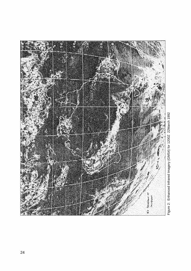
The atmosphere over a large part of Western Australia was unstable which, coupled with high levels ofmoisture (dewpoint temperatures were of the order of 17°C) and triggered by afternoon heating, gave riseto embedded thunderstorms within a pre-existing middle level cloud mass.
From the infrared satellite image (GMS4) taken at 1130Z on 22 March (Figure 2), it can be seen that themost active weather area Australia-wide was located in the general vicinity of the incident.
Upper level winds over Western Australia:The 300 hPa contour analysis for 1200Z 22 March 1992 issued by the National Meteorological Centre(NMC) Melbourne is shown in Figure 3. The Meekatharra area was lying nearly halfway between a ridgeover Alice Springs and a trough off the west coast. The pattern was slow moving.
Observational evidence in support of this analysis is shown in Figure 4. Bureau of Meteorology upper airstations are supplemented by reports from aircraft (both the BAe 146 involved in the incident and anotherBAe 146 on the same route that night) and indicate that winds along the track were generally northwesterly at30 to 40 knots, although a northerly wind at 20 knots was reported by the BAe 146 just prior to the incident.
The wind profile through the atmosphere was essentially similar down to near 14000 feet but withnorthwesterly winds easing off to 10 to 20 knots.
From 14000 feet to 10000 feet, the airflow appeared to converge into the area between Meekatharra andthe west coast, and below 7000 feet the structure of the trough became apparent.
The structure of the atmosphere at the time of the incident:The high resolution enhanced infrared satellite image for 1230Z 22 March 1992 (Figure 5) indicates theapproximate cloud top temperatures at the time of the incident. The position of the aircraft is shown.
19

The black area to the east of the aircraft represents the coldest cloud (somewhere between minus 63°C andminus 68°C), and hence the strongest convective activity within the cloud system.
Cloud top temperatures in the vicinity of the aircraft were around minus 57°C. Observations by the flight crewindicate the BAe 146 was flying in clear air at 31000 feet with an OAT of minus 39°C, prior to the incident.
The satellite imagery suggests that the cloud tops were being blown off towards the southeast, consistentwith the observed northwesterly environmental flow. The cloud pattern is asymmetrical, with the black(coldest) area displaced to the east of the main cloud mass. This may have been the result of earlierconvection to the west which was in the process of dissipating at the time of the imagery. The pilot(personal communication) mentioned that there appeared to be decaying cells in the area.
The freezing level (height of the zero°C isotherm) in the area of the incident was estimated fromsurrounding radiosonde data to be near 13800 feet.
A possible explanation for the observed temperature anomalies:It is significant that the temperature anomalies occurred on the western side of and in close proximity tothe area of strongest convection within the cloud system. The nearest temperature sounding to theincident was taken at Learmonth Meteorological Office, and this indicated that the tropopause was locatedat around 41000 feet. The convective turrets from the principal thunderstorm cell penetrated thetropopause (normally the cap for cloud development and the cause of the flat anvil shape of welldeveloped cumulonimbus clouds) and over-shot into the stratosphere.
It is most likely that air flowing out of the thunderhead encountered environmental northwesterly winds.This confluence of air of differing origins and physical characteristics would have caused the outflowing airon the western flank of the thunderhead to return from the stratosphere to the troposphere (Fig. 6) and, indescending, to rapidly warm. Adiabatic warming of a parcel from the top of the thunderhead (temperatureof around minus 62°C determined from infrared satellite imagery) to the flight level of the aircraft (31000feet) would produce a temperature near to minus 28°C which is in good agreement to the reportedanomaly (Fig. 7).
A possible reconstruction of the state of the atmosphere at the time of the incident is shown in Fig. 8. Theflight path of the aircraft is shown, indicating where descent to various flight levels occurred. The graph iszeroed at the point where significant anomalous warming first takes place and corresponds to around12:36:00Z . The diagram looks north south and shows the relative position of the main convective cell andthe most probable cloud profiles. A graph of the OAT is superimposed on the diagram to show the extentof the anomalous warming.
Possible characteristics of the temperature anomaly.This type of phenomenon has not been well documented in the scientific literature, and the question wasraised of how common these events are in the atmosphere.
A similar event was reported to have occurred on the western periphery of tropical cyclone Kerry in 1979,when a Boeing 747 enroute from Port Moresby to Brisbane encountered an 18°C temperature rise in 32 nmwhen diverting to avoid a strong convective area (Holland et al, 1984). The aircraft was flying at 37000 feetand lost considerable power as a result of the encounter with the temperature anomaly.
A survey was initialled asking QANTAS pilots if they had ever encountered similar temperature rises. Theresult was overwhelmingly in the affirmative. The phenomenon appears to be reasonably common,particularly in tropical areas.
The phenomenon is almost certainly the result of folding of stratospheric air back into the tropospherewith concomitant warming as it descends. The most likely mechanism for this to occur is strongconvection (and for the pilot, strong returns on his weather radar). It is reasonable to assume that, wherethere is strong thunderstorm activity, there is a fair likelihood that an area of anomalous warming will bepresent somewhere around the storm cell.
20

The vertical extent of the anomaly is difficult to ascertain and is probably dependent on the strength of theoutflow from the storm and its interaction with the environmental flow, but in this case, with thetropopause at 41000 feet, observations from the aircraft indicated that the warming stopped abruptly at28000 feet.
The horizontal distribution of the anomaly is most likely to be concentrated in a zone of confluencebetween the environmental flow and the thunderstorm outflow, as that would be the area where maximumdescent was occurring, associated with the largest perturbation of the tropopause. In this case the anomalytook place on the western flank of the main convective activity. It is unlikely that any anomalous warmingwould have occurred on the eastern side of the storm as there would have been no confluence and notropopausal perturbation. The temperature anomaly was observed over a horizontal distance ofapproximately 60 nm. By comparison, the incident in 1979 took place within a distance of near 40 nm.
It is appropriate to relate some of the pilots’ comments here. His normal practice (and it is understoodthat this is standard practice) when diverting around radar echoes was to ensure a buffer of 10 nm betweenthe radar echo and the aircraft. As an extra safety margin on this occasion he diverted 30 nm from thestrongest echo and in doing so encountered the phenomenon. Perhaps this is a reason why it is notencountered regularly by aircraft - most pilots (in maintaining the normal 10 nm buffer) may travelbetween the anomalous zone and the thunderstorm. It is estimated that in the incident associated withtropical cyclone Kerry in Queensland, the aircraft encountered the temperature anomaly about 40 nm onthe western flank of the main convection area.
The BAe 146 pilot also commented that he had been flying in an area of innocuous radar returns - visibleas a “green fuzz” on his radar screen. He noticed that the warming commenced as they flew along theboundary between the weak returns and the clear air. It is suggested that that boundary was an indicationof the delineation between air masses of differing characteristics.
Another interesting comment was that prior to the incident there had been an incredible display of St Elmo’sFire, the best that he had ever seen. Whether this was a precursor to this type of event or merelycoincidence is conjectural at this stage.
Summary and conclusions:A BAe 146 aircraft enroute from Karratha to Perth experienced an extraordinary warming of up to 20°Cabove the environmental temperature for approximately 60 nm along its track. The incident took placeabout 120 nm northwest of Meekatharra, in close proximity to thunderstorm activity.
The probable cause of the warming was the descent of air from the stratosphere, associated with theinteraction of air outflowing from the thunderhead and the surrounding environmental air. Estimation ofthe extent of warming by descent of an air parcel gave close agreement to OAT recorded by the aircraft.
The probable vertical extent of the temperature anomaly was from around 38000 feet (where theanomalous warming of descending air from the stratosphere became greater than 5°C) to around 28000 feet,where the anomaly was observed to abruptly stop.
This localised area of warming is probably present in association with the life cycle of those thunderstormswhich are energetic enough to penetrate the stratosphere, as long as the environment is conducive to thesetup of a perturbation on the tropopause that will allow the downward transport of stratospheric air withresultant rapid warming.
This suggests the strength of the wind regime of the atmosphere is critical and should neither be too strong(say greater than 40 knots) nor too weak (say less that 20 knots), otherwise the phenomenon may notoccur. The direction of the wind flow relative to the outflow is also critical in identifying where (relative tothe cumulonimbus outflow) the anomaly will occur.
The anomalous zone appears to exist away from the main convective area, and may be transitory in nature,dependent on the current strength of the storm and its interaction with the environment. It is also
21

relatively small in area. It appears nonetheless to be a significant hazard for aviation and the problem ofavoiding these anomalies needs to be addressed by the industry.
Reference:Holland, G.J., T.D. Keenan, and G.D. Crane, 1984: Observations of a Phenomenal Temperature Perturbationin Tropical Cyclone Kerry (1979). Mon.Wea.Rev., 112, pp 1074-1082.
22

Fig
ure
1: M
SLP
Ana
lysi
s fo
r 12
00Z
22
Mar
ch 1
992
23
24
Fig
ure
2: E
nhan
ced
Infr
ared
Imag
ery
(GM
S4)
for
1200
Z 2
2Mar
ch 1
992

25
Fig
ure
3: 3
00 h
Pa
cont
our
heig
ht a
naly
sis
for
1200
Z 2
2 M
arch
199
2

26

27
Fig
ure
5: E
nhan
ced
Infr
ared
Imag
ery
(GM
S4)
for
Wes
tern
Aus
tral
ia fo
r 12
00Z
22
Mar
ch 1
992.
App
roxi
mat
e lo
catio
n of
inci
dent
den
oted
by
(x).

28
Figure 6: Schematic of interaction between environmental northwesterly winds andthunderstorm outflow. Airep from BAe146 is plotted relative to the storm.

29
Figure 7: Temperature profile from Bureau of Meteorology station closest to incident (Learmonth)

30
Fig
ure
8: S
chem
atic
nor
th/s
outh
cro
ss-s
ectio
n of
atm
osph
ere
at ti
me
of in
cide
nt s
how
ing
mos
t lik
ely
clou
d st
ruct
ure.
Out
side
air
tem
pera
ture
(O
AT
) fr
om B
Ae1
46 s
how
ing
war
min
g re
lativ
e to
sto
rm p
ositi
on is
als
o pl
otte
d.


APPENDIX 3
BAe 146 MANUFACTURER’S OPERATIONS MANUAL
NOTICE TO AIRCREW
OPERATIONAL NOTICE : NO.OP25
APPLICABILITY : BAe 146 ALL SERIES
VALID: : Until further notice
ENGINE BLEED BAND OPEN WITH AIRFRAME OUTERWING AND TAIL ANTI-ICE ON ABOVE 25,000 ft.
Following further engineering studies the advice pertaining to operation of the engine with airframe anti-icing at high
altitude has been reviewed; Notice to Aircrew Op 22 is withdrawn, to be replaced by the amplified advice contained in
this notice. A Flight Manual Temporary Revision will be published.
With engine and airframe anti-icing selected ON at high altitude, the N2 speed at which the engine bleed band opens
increases markedly. This is because the high bleed demand increases the ratio between fuel flow and compressor
discharge pressure; this ratio is the criteria used to control the engine’s bleed band. At high ambient temperatures the
bleed band may be signalled open at N2 speeds normally associated with Long Range Cruise/Rough Air Speeds,
particularly when the thrust lever has been retarded to decelerate the aircraft and then advanced to stabilise speed. If
this should occur, the effect of the bleed band being open further increases this ratio, introducing a hysteresis effect
such that, in the extreme case, the bleed band cannot be closed by advancing the thrust lever. It is therefore necessary
to remove some or all of the air extraction first. Once the bleed band has been closed in this way, full air bleed is
available, provided that an appropriate N2 speed is set prior to selecting airframe anti-icing ON.
The relationship between N1 and N2 is different with the engine interstage bleed open and closed. When the bleed
band opens N1 speed is decrease by 5-8%, causing an associated reduction in thrust, while N2 remains nominally
constant; a rise in TGT may also occur. At high altitude the trigger point for the bleed band to open is normally
increased to 85% N2 and may be further increased by airframe bleed. The indications of bleed band opening will be
affected by the TMS mode in use, and an N1 oscillation of about 1.5% may occur if the bleed band operates with the
TMS engaged in N1 SYNC mode. This oscillation is caused by non-master engine(s) operating close to the bleed band
operating trigger point such that the bleed band is continually opening and closing. The oscillation can be stopped by a
small change in the N1 of the master engine.
In high ambient temperatures above FL250 with airframe anti-ice on the engine bleed band may open. This is
characterized by:
a) A high TGT (840 deg.C or above) with relatively low N1.
b) N1 is less than N2.
c) Slow engine response to thrust lever advance giving rapid TGT rise, in extreme ambient conditions the TGT
rise could occur without corresponding N1 and N2 increase.
d) A reduction in thrust due to low N1.
When airframe anti-ice is required above FL250:
1) Select cabin air to RECIRC.
2) Set all engines to 90% N2 prior to selecting wing and tail anti-ice on, thereafter maintain 87% N2. Airframe
inner wing de-ice should not be used above FL250.
2.00.23
NTA OP25 Page 1 of 3
Printed in England Iss.No.1 Nov 91
32

BAe 146 MANUFACTURER’S OPERATIONS MANUAL
NOTICE TO AIRCREW
OPERATIONAL NOTICE : NO.OP25 - continued
When operating the engines with TMS control and TGT limiting at 857 deg.C the thrust levers should not be further
advanced. Before disconnecting the TMS the thrust levers must be retarded to ensure that the centering of the TMS
actuators does not cause the engine temperature limit (882 deg.C) to be exceeded.
If the engine bleed band opens, carry out the ENGINE BLEED BAND OPEN WITH AIRFRAME ANTI-ICE ON ABOVE FL250
procedure attached, which will be published in MOM Col 3 Pt 2: Abnormal and Emergency Checklist;
NOTE: 1. BAe Mod HCM.01285A inhibits the airbrake auto retract feature, thus airbrake
can be used to initiate descent whilst maintaining 87% N2.
2. The engine maximum temperature limit is to be amended by flight manual
revision. The amendment will allow an overswing in the range 882 deg.C to
904 deg.C. for up to 15 sec.
ENGINE BLEED BAND OPEN WITH AIRFRAME OUTERWING AND TAIL ANTI-ICE ON ABOVE 25,000 ft.
NOTE: Engine bleed band open with airframe outerwing and tail anti-ice selected on can
be indicated by the following symptoms;
(1) A high TGT (840 deg. C or above) with relatively low N1,
(2) N1 is less than N2,
(3) Slow engine response to thrust lever advance giving rapid TGT rise. In extreme
ambient conditions the TGT rise could occur without corresponding N1 or N2 increase,
(4) A reduction in thrust due to low N1.
All AIRFRAME ANTI-ICE/DE-ICE : OFF
If continued airframe anti-icing is required:
ENG ANTI-ICE : : : Confirm ON
CABIN AIR : : : Confirm RECIRC
TMS : : : Disconnect
NOTE: When disconnecting TMS observe engine limits.
THRUST LEVERS (all) : : Adjust to 90% N2 Minimum
OUTER WING & TAIL ANTI-ICE : : ON - Monitor N1/N2/TGT
NOTE: The INNER WING DE-ICE should not be used above FL250.
THRUST LEVERS : : Maintain 87% N2 minimum
(Continued ...)
2.00.23
NTA OP25 Page 2 of 3
Printed in England Iss.No.1 Nov 91
33

BAe 146 MANUFACTURER’S OPERATIONS MANUAL
NOTICE TO AIRCREW
OPERATIONAL NOTICE : NO.OP25 - continued
Is bleed band still open ? NO No further action (continue
to monitor engines). Revert
to normal operation when
YES clear of icing conditions.
OUTER WING & TAIL ANTI-ICE .. OFF
Affected engine:
ENG AIR .. .. OFF
ENG ANTI-ICE .. .. OFF
THRUST LEVER .. .. Re-adjust to 90% N2.
Is bleed band still
open after 2 minutes ? NO ENG ANTI-ICE .. .. ON
ENG AIR .. .. ON
OUTER WING & TAIL
ANTI-ICE .. .. ON
If bleed band opens descend
YES as soon as possible to
FL250 or below.
When clear of icing conditions
INNER WING DE-ICE .. ON for
1 minute
ENG ANTI-ICE .. .. ON
THRUST LEVER .. .. Retard to maintain
below 857 deg.C TGT.
Descend as soon as possible to FL250 or below.
ENG AIR .. ON
OUTER WING & TAIL ANTI-ICE .. ON (if req’d)
When clear of icing conditions.
INNER WING DE-ICE .. .. ON for 1 minute.
* * *
2.00.23
NTA OP25 Page 3 of 3
Printed in England Iss.No.1 Nov 91
Note: This notice has been reproduced by BASI from the original document
34