british sulphur publishing presents … sulphur publishing presents nitrogen '99 caracas,...
TRANSCRIPT

BRITISH SULPHUR PUBLISHING PRESENTS
NITROGEN '99 Caracas, Venezuela
28 February - 2 March, 1999
CASALE GROUP EXPERIENCE IN REVAMPING AMMONIA, METHANOL AND UREA COMPLEXES
by M. Badano, Ammonia Casale S.A. and F. Zardi, Urea Casale S.A.
Via Sorengo 7, CH-6900 Lugano, Switzerland
paper/conf/amm/meetings/nitrogen99paper.doc

AMMONIA CASALE S.A.
_______________________1_______________________ NITROGEN '99
Caracas, Venezuela, 28 February - 2 March, 1999
BRITISH SULPHUR PUBLISHING PRESENTS
NITROGEN '99 Caracas, Venezuela
28 February - 2 March, 1999
CASALE GROUP EXPERIENCE IN REVAMPING AMMONIA, METHANOL AND UREA COMPLEXES
by
M. Badano, Ammonia Casale S.A. and F. Zardi, Urea Casale S.A. Via Sorengo 7, CH-6900 Lugano, Switzerland
ABSTRACT This paper presents the approach taken by the Casale companies (Ammonia Casale S.A., Methanol Casale S.A. and Urea Casale S.A.) to revamp ammonia and urea plants and to transform an ammonia plant into a methanol plant at the Togliatti Azot complex located in Russia, in order to reduce the energy consumption and increase production capacity with a minimum investment cost and the highest benefits. The approach utilized is based on a number of new technologies developed especially by the Casale companies, that are here illustrated. Ammonia Casale has successfully completed the revamp of four Chemico ammonia converters and loops with the capacity of 1360 MTD each, by installing its patented axial-radial internals and make-up gas drying units by ammonia washing, obtaining a considerable energy saving. Methanol Casale has designed a new 1350 MTD methanol plant reusing some ammonia plant equipment available at site. Among them a complete GIAP, top-fired, steam reforming and heat recovery section, high pressure waste heat boilers, air coolers, etc. were re-utilised. Urea Casale has revamped two 1500 MTD urea plants originally designed according to the Snamprogetti technology. By installing the Casale-Dente high efficiency trays in the reactor, a heat recovery section, the Casale Urea Recovery system and revamping the CO2 compressor, the capacity was increased by 15 % with a significant steam consumption reduction. paper/conf/amm/meetings/nitrogen99paper.doc
AMMONIA CASALE S.A.
_______________________2_______________________ NITROGEN '99
Caracas, Venezuela, 28 February - 2 March, 1999
INTRODUCTION Casale Companies (Ammonia, Urea, Methanol and Chemicals) have a wide experience in revamping ammonia, urea and methanol plants having revamped more than 100 ammonia converters, over 50 urea plants and 16 methanol plants with different capacities. The case history described in this paper is an example of the peculiarity of Casale companies to revamp complete and integrated ammonia-urea large complexes. Togliatti Azot (TOAZ) chemical complex is located at Togliatti, Samara region, (C.S.I.) and it has the largest installed capacity of ammonia production in a single complex in the world with just less than 10’000 MTPD (11’000 STPD) divided among 4 Chemico plants (which went on stream at the end of the seventy’s) and 3 GIAP AM 76 (which went on stream in middle of the eighty’s), each plant designed for abut 1’360 MTPD (1500 STPD). Two SNAM Progetti urea plants were commissioned in ‘79-‘80, while a new methanol plant, designed by Methanol Casale S.A. is under erection and will be on stream by the end of this year.

AMMONIA CASALE S.A.
_______________________3_______________________ NITROGEN '99
Caracas, Venezuela, 28 February - 2 March, 1999
1 - Ammonia plant revamping Ammonia Casale S.A. started to collaborate with TOAZ in ’91 getting the contract to revamp the 4 Chemico ammonia converters and to install a make up gas drying unit by ammonia washing in the same plant. The ammonia revamping was carried out in two phases: 1st phase: revamping of ammonia converter internals (1993/94) 2nd phase: installation of MUG drying unit (1994/95) 1.1 - 1st phase: Chemico ammonia converter modernization 1.1.1 Technology back-ground. The ammonia converter is, of course, one of the most important items when planning a revamp for energy saving or capacity increase, and in fact it is, in most cases, the first item to be revamped thanks to the relatively low cost and very high return. AMMONIA CASALE is very active in this field and has introduced fundamental innovations in the converter design and revamping, such as the "in situ" modification of bottle-shaped converters as the Kellogg ones, and the three-bed intercooled configuration that is being used by CASALE for over ten years now. This activity has been very rewarding and now AMMONIA CASALE has more then 100 converters on stream, out of which about 50 are "in situ" modifications, and the majority of the others are revamps of full-bore opening converters. The most important ingredients for this success are the axial radial beds, (see figure 1), and the three-bed configuration adopted both for revamping of any kind of converters and for new converters as well (see figure 2).
Fig. 1 - Axial-Radial Flow These two elements give the highest utilization of the catalyst volume available, thanks to the axial-radial configuration, and the most thermodynamically efficient cartridge configuration, the three-bed interchanger one, with cooling achieved by means of heat exchanger both between 1st and 2nd bed and between 2nd and 3rd bed.
Fig. 2 - 3 Beds - 2 Interchangers

AMMONIA CASALE S.A.
_______________________4_______________________ NITROGEN '99
Caracas, Venezuela, 28 February - 2 March, 1999
It is possible to use small-size, more active catalyst with the axial-radial configuration, and it is well known that small-size catalyst is more efficient than the large-size one. Therefore, the design of the cartridge lay-out with three adiabatic beds and two interchangers, and the use of 1.5 ÷ 3 mm size catalyst, makes it possible to obtain a high ammonia conversion and a low pressure drop. A particular feature of the design is its simplicity: the catalyst-containing baskets are easy to be handled and have a low cost. Moreover, the use of a reverse bottom increases the catalyst filling
efficiency (see figure 2). 1.1.2 - Case history The original Chemico converters were designed with 3 beds and quenches between 1st and 2nd bed and 2nd and 3rd bed. The configuration was changed, by in-situ modification, keeping the same 3 beds lay out, but installing 2 interchangers: one between 1st and 2nd bed and one between 2nd and 3rd bed and adopting the Casale patented axial-radial flow of the gas through the beds.

AMMONIA CASALE S.A.
_______________________5_______________________ NITROGEN '99
Caracas, Venezuela, 28 February - 2 March, 1999
Fig. 3 - Chemico ammonia converters (original and revamped)
The performances achieved by the modified converters have been indicated in the following table (see Table 1).

AMMONIA CASALE S.A.
_______________________6_______________________ NITROGEN '99
Caracas, Venezuela, 28 February - 2 March, 1999
Table 1: Performances of ACSA internals in Chemico ammonia converters
unit Original Chemico
ACSA revamping (Test run)
Ammonia MTPD 1’360 1’345 STPD 1’500 1’482
Converter pressure bar a 311 197
INLET Temperature °C 141 140 °F 286 284 Ammonia conc. % vol. 3.5 2.37 Inerts conc. % vol. 16.7 10.83
OUTLET Temperature °C 328 295 °F 622 563 Ammonia conc. % vol. 16.7 17.04
Energy saving kcal/MT 400’000 Btu/ST 1’400’000
1.2 - 2nd phase: MUG drying unit The 2nd phase of the ammonia loop revamping started as soon as the 1st phase was completed. It is well known that the advantage of feeding dried make-up gas to the loop in terms of reduction of evaporating ammonia and saving of power over the circulator compressor. Two main techniques can be used: 1. molecular sieves 2. MUG washing with liquid ammonia. Even if the first solution gives a higher energy saving, the second is cheaper and more reliable. For these reasons TOAZ chose to adopt the second alternative. The scheme proposed and adopted is showed in figure 4.
AMMONIA CASALE S.A.
_______________________7_______________________ NITROGEN '99
Caracas, Venezuela, 28 February - 2 March, 1999
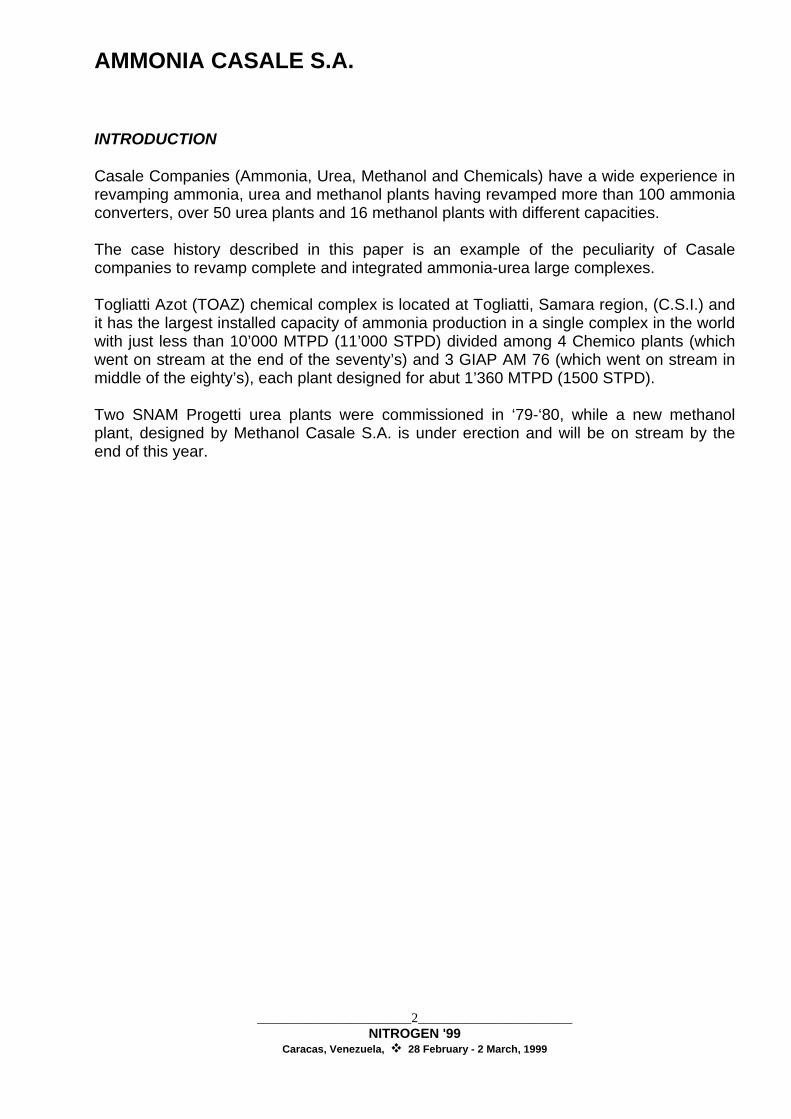
Fig 4 - Revamped Chemico Ammonia Loop
The main modifications are here below summarised: a) Make up gas compressor section:
About one third of the liquid ammonia produced, coming from the separator G-701 and G-702, is mixed with the make up gas exiting the 2nd interstage separator of K-601 compressor and fed to the co-current ammonia wash contactor F-1601; the MUG is then separated from the liquid ammonia in G-1602 and then reheated in E-1610 cooling down the 3rd stage compressor discharge. The liquid ammonia, contained the water and the carbon oxides removed from the MUG, is then sent back to the ammonia catch pot G-703.
b) Ammonia synthesis loop:
The modification of the syn-loop mainly concerned the piping lay out. Thanks to the absence of oxygenate compounds in the MUG, the gas could be fed directly to the ammonia converter inlet, just up stream the hot gas-gas exchangers E-703 A/B. Furthermore the purge gas point was moved from the exit of the hot ammonia separator G-701 to the exit of the cold ammonia separator G-702. The final MUG air cooler E-607 was reused in parallel with the loop main air cooler E-705 reducing the evaporating ammonia required from the chillers (E-709 and E-708 A/B). The 4 ammonia washing units went on stream between 1994/95 with an energy saving of about 90’000 kcal/MT of ammonia (324’000 BTU/ST).

AMMONIA CASALE S.A.
_______________________8_______________________ NITROGEN '99
Caracas, Venezuela, 28 February - 2 March, 1999
2 - Methanol plant 2.1 - Technology back-ground. From 1928 onwards Ammonia Casale S.A. started to engineer and construct methanol synthesis plants as well reaching 40 % of the world production in the years 1928 ÷ 1930. Then the Ammonia Casale market share activity decreased down to the 10 % of the late nineteen sixties, due to the massive new entries based on the second generation, low pressure large units. This activity has been recently resumed by Methanol Casale S.A. with a very successful breakthrough in the field of the present methanol synthesis technologies. In collaboration with Imperial Chemical Industries (ICI), Methanol Casale S.A. is modernizing several plants based on ICI technology by introducing original innovations: the A.R.C. - Advanced Reactor Concept (see figure 5), and new methanol plants have been built or are under construction using the most advanced designs developed by Methanol Casale.
Fig. 5 - A.R.C. converter The following results, among others, can be obtained when retrofitting: reduced synthesis gas specific consumption, and raw methanol quality improvement methanol synthesis. Adiabatic methanol converters have also been studied and patented by Methanol
Casale S.A. in order to recover in a more efficient way the reaction heat. The horizontal converter (see figure 6) is one of these and this technology has been applied to the new TOAZ methanol plant. Due to the milder operating conditions in terms of pressure and temperature than in an ammonia converter, the horizontal lay-out becomes an attractive solution for modern large capacity reactors.
quench slots
bed 1
bed 2
bed 3
bed 4
detail of the ARC mixer

AMMONIA CASALE S.A.
_______________________9_______________________ NITROGEN '99
Caracas, Venezuela, 28 February - 2 March, 1999
The pressure vessel is a simple cylindrical shell laid down horizontally and contains all catalyst baskets and inter beds heat exchangers and boilers. Fig. 6 - Horizontal converter
Bed 1 Bed 2 Bed 3 Bed 4 OutletInlet
The important features of the CASALE HORIZONTAL CONVERTER design are as follows: ♦ Possibility to recover the reaction heat raising steam up to 25 bar. ♦ Simple mechanical design: the catalyst baskets are just empty containers, without
complicated internals like tubing, coils etc. ♦ All exchangers are completely removable form the pressure shell, for easy
maintenance. ♦ Single vessel lay-out, for any capacity, up to 3000 mtd and more (3300 std). ♦ Low pressure drops thanks to the cross flow pattern, rather than axial, of the catalyst. ♦ Maximum utilization of the vessel's internal volume. ♦ The design allows to fill with catalyst more than 80 % of the vessel volume thus
resulting in compact, low cost units. Further more no external high temperature piping is necessary to connect the exchangers. Also the steam/bfw pipework is greatly simplified since the steam drums can be located very close to the reactor. Standard, well proven shell and tube heat exchangers are used and a very simple foundation lay-out. The package of reactor and exchangers needs only two saddles for support. The converter and related equipment, like boilers and steam drums, are all at ground level. 2.2 - Case history
In ’94, due to the rise of methanol prices and to the low price of ammonia, TOAZ asked Methanol Casale to study the possibility to transform one of the 3 GIAP AM 76 ammonia plants in one methanol plant keeping the same production capacity. At the end of ’95 TOAZ decided not to transform one of the existing ammonia plant but to build a new methanol plant, using as many as possible the equipment present in its warehouse, originally design for the eighth ammonia plant.

AMMONIA CASALE S.A.
_______________________10_______________________ NITROGEN '99
Caracas, Venezuela, 28 February - 2 March, 1999
A new methanol plant with a capacity of 1350 MTPD (1477 STPD) was design by methanol Casale S.A. taking into account TOAZ requirements not only to maximise the use of the equipment present at site, but also to maximise the manufacturing of the new equipment inside the C.I.S. countries that was done under Casale supervision and responsibility. In the following flow sheet we have pointed out the equipment reused and manufactured within C.I.S. countries and abroad. There are two main features of the new methanol plant: a) the redesign of the existing ammonia reformer in order to meet the requirement of a
new methanol reformer; b) the new horizontal methanol converter

AMMONIA CASALE S.A.
_______________________11_______________________ NITROGEN '99
Caracas, Venezuela, 28 February - 2 March, 1999
AMMONIA CASALE S.A.
_______________________12_______________________ NITROGEN '99
Caracas, Venezuela, 28 February - 2 March, 1999
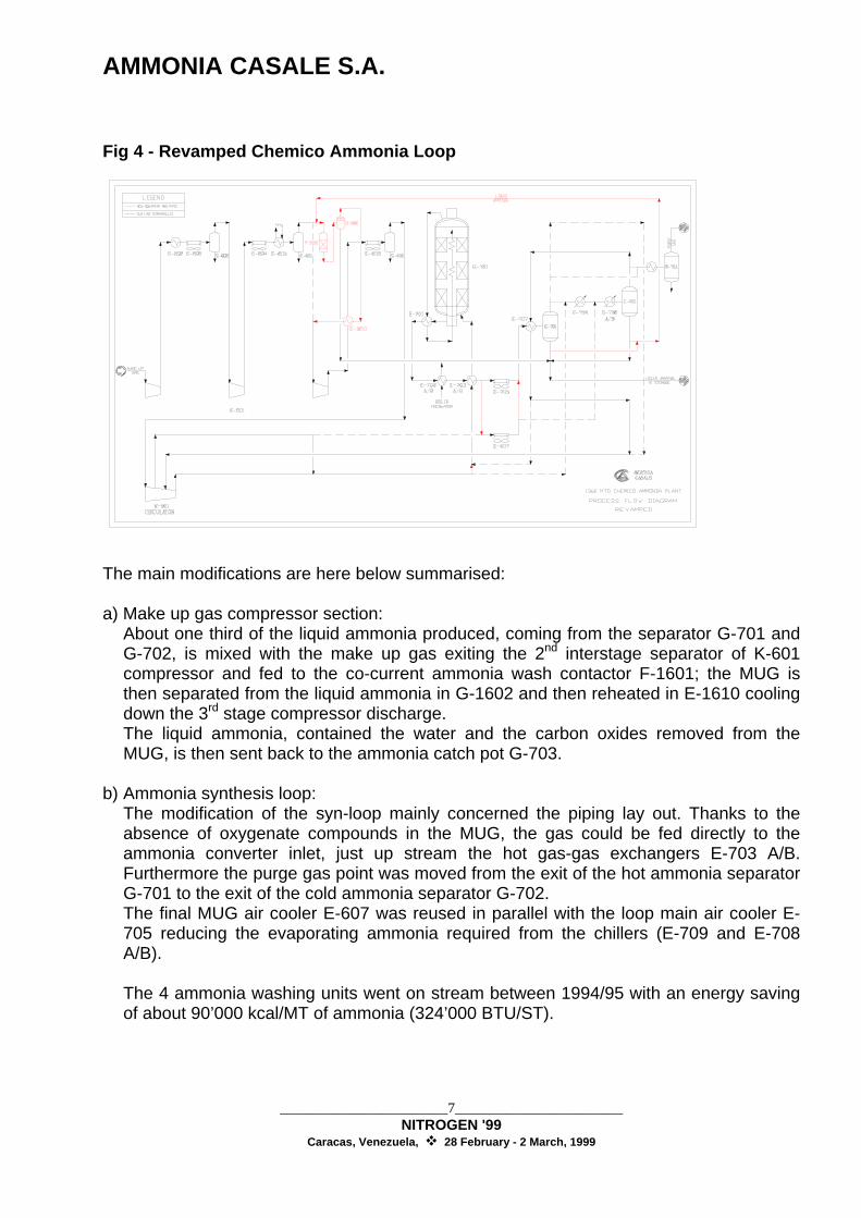
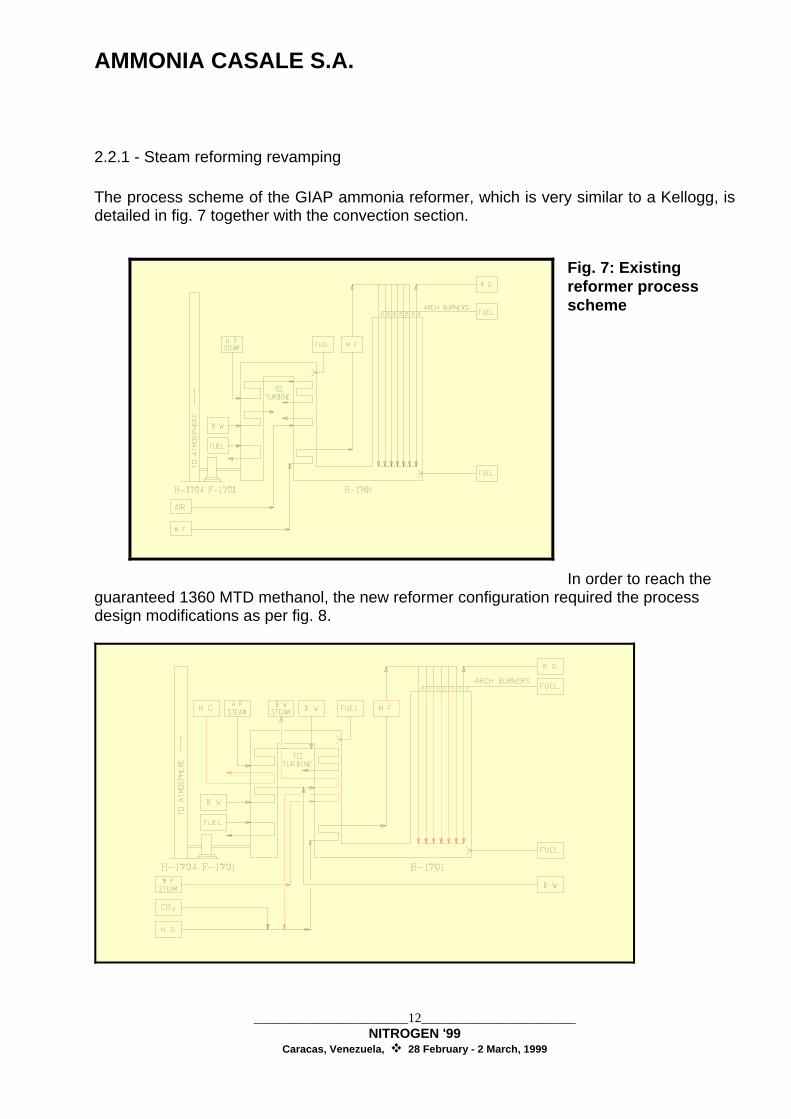
2.2.1 - Steam reforming revamping The process scheme of the GIAP ammonia reformer, which is very similar to a Kellogg, is detailed in fig. 7 together with the convection section.
Fig. 7: Existing reformer process scheme In order to reach the
guaranteed 1360 MTD methanol, the new reformer configuration required the process design modifications as per fig. 8.

AMMONIA CASALE S.A.
_______________________13_______________________ NITROGEN '99
Caracas, Venezuela, 28 February - 2 March, 1999
Fig. 8: Retrofitted reformer process scheme The main revamping features are the following: - Increase of reforming catalyst quantity from 20,8 m3 to 37,6 m3 by changing catalyst
tubes; - Increase of radiant heat liberation from 170'000'000 kcal/h to 227'000'000 kcal/h by
modification of roof burners; - Addition of one BFW heater/boiler convection coil; - Addition of one natural gas preheater convection coil; - Utilization of existing air preheater convection coil to heat MP process steam; - Addition of inline de-superheater between 1st and 2nd stage H.P. steam
superheaters to control the temperature at H.P. turbine inlet. 2.2.2 - New horizontal methanol converter The above described features of the Horizontal Methanol Converter have led to the realization of a reactor with the following benefits: - low cost, including installation - reduced energy consumption thanks to the low pressure drop - long term reliability since very simple, standard design equipment are used - very easy maintenance of the internals, should it be required - catalyst loading / unloading of the beds can be carried out in parallel The horizontal converter under installation in TOAZ methanol plant has the following features: - Capacity: 1350 MTD - Lay-out: 4 beds with boiler after, respectively, bed 1 and 2 and one gas/gas exchanger
after bed 3 - Pressure of the steam raised: up to 18 bar.
AMMONIA CASALE S.A.
_______________________14_______________________ NITROGEN '99
Caracas, Venezuela, 28 February - 2 March, 1999
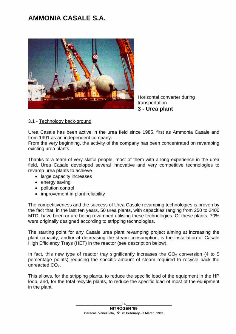
Horizontal converter during transportation 3 - Urea plant
3.1 - Technology back-ground Urea Casale has been active in the urea field since 1985, first as Ammonia Casale and from 1991 as an independent company. From the very beginning, the activity of the company has been concentrated on revamping existing urea plants. Thanks to a team of very skilful people, most of them with a long experience in the urea field, Urea Casale developed several innovative and very competitive technologies to revamp urea plants to achieve :
• large capacity increases • energy saving • pollution control • improvement in plant reliability
The competitiveness and the success of Urea Casale revamping technologies is proven by the fact that, in the last ten years, 50 urea plants, with capacities ranging from 250 to 2400 MTD, have been or are being revamped utilising these technologies. Of these plants, 70% were originally designed according to stripping technologies. The starting point for any Casale urea plant revamping project aiming at increasing the plant capacity, and/or at decreasing the steam consumption, is the installation of Casale High Efficiency Trays (HET) in the reactor (see description below). In fact, this new type of reactor tray significantly increases the CO2 conversion (4 to 5 percentage points) reducing the specific amount of steam required to recycle back the unreacted CO2. This allows, for the stripping plants, to reduce the specific load of the equipment in the HP loop, and, for the total recycle plants, to reduce the specific load of most of the equipment in the plant.

AMMONIA CASALE S.A.
_______________________15_______________________ NITROGEN '99
Caracas, Venezuela, 28 February - 2 March, 1999
If the required capacity increase is not too high, it is, therefore, enough to install the HET to de-bottleneck the HP section, eliminating the need for additional HP equipment and thus maximising the capacity increase with minimum investment. It is, in fact, very important to avoid, for small capacity increase projects, any change in the HP section which would drastically increase the return time of the investment. Through a complete check of the downstream section, the few changes /additions necessary to eliminate the bottlenecks which would still be present after HET installation, are determined. With this approach, i.e. installation of HET and few changes/additions in the downstream section, an increase in capacity up to 30÷35% can be obtained. This approach can be applied for both CO2 and NH3 stripping plants and for conventional total recycle plants. Urea Casale High Efficiency Trays After having found that heat and mass transfer phenomena are limiting the efficiency of most of the existing urea reactor, a new reactor tray design has been developed in order to improve heat and mass transfer rates. It was, in fact, also found that with the existing tray design the exchange between the liquid and the vapour phase (both present in a urea reactor) was, for several reasons, not optimal thus consequenting in poor heat and mass transfer between the two phases. The design improves the tray geometry realising better contact patterns of the phases, reducing the path length of the eddies' streamlines into the emulsion (mixed phase of bubble and liquid) and drastically increasing emulsion to clean liquid boundary surface. The new trays are, in fact, designed so that:
• separate and distributed paths through the tray are provided. They guarantee a steady state flow of the two phases and better approach an even uniform flow of the two phases throughout the whole reactor.
• These separated paths through the tray are chosen so that a very high mixing efficiency between vapour and liquid is obtained. Consequently a very high mass and heat transport within the liquid phase is realised.
• With an appropriate design, the diameter of the generated vapour bubbles is smaller than in any previous design. By consequence, the interfacial surface, for mass and heat transfer, is increased.
• A much larger surface of exchange between emulsion and clean liquid is created. • The quite shorter path length of recirculation streamlines into the emulsion phase
significantly decreases the transport resistance’s.

AMMONIA CASALE S.A.
_______________________16_______________________ NITROGEN '99
Caracas, Venezuela, 28 February - 2 March, 1999
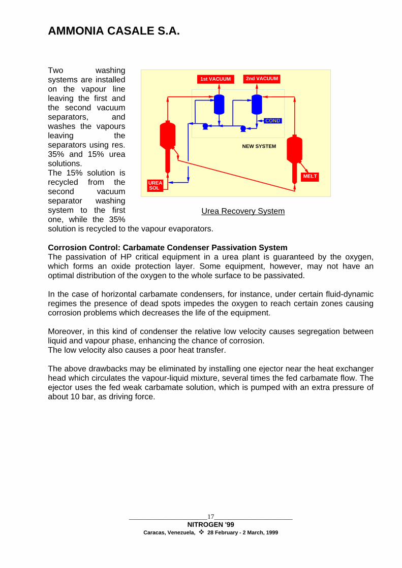
The trays (see Fig. 9) are made up by several inverted U beams with large perforations for liquid passage on the bottom wings, and small perforations for gas passage on the sloping and top sections. With this unique design, very small bubbles are generated, and by consequence, very high specific surface for the mass and heat transfer is obtained. This advantage is combined with a very high efficiency in the mixing between vapours and liquid. The above approach has been used to revamp the urea plant owned by Toaz in order to achieve capacity increase and energy consumption reduction. In addition to the above described technology, other technologies have been developed by Urea Casale for the cases when large capacity increase are required. With these technologies, it is possible to reach increases of 50÷60 % and more. In order to reduce the urea carry over from vacuum evaporators and the corrosions in the carbamate condenser Urea Casale has developed two technologies called Urea Recovery System (URS) and Carbamate Condenser Passivation System (CCPS) that are described here below. These technologies have also been applied for the revamping of the Toaz plant. Urea Recovery System (URS) A combined system can be offered for the recovery, from vacuum vapours, of 96-97% of urea carry-over as 35% urea solution that is directly reprocessed in the vacuum evaporators. With this system the urea content in the process condensate going to the waste water treatment section is brought down to 400÷500 ppm.
VAP. VAP.
VAP. VAP.
LIQ.LIQ.LIQ.
VAP.
VAP.
LIQ.
Fig.9 - Casale High Efficiency trays
AMMONIA CASALE S.A.
_______________________17_______________________ NITROGEN '99
Caracas, Venezuela, 28 February - 2 March, 1999
Two washing systems are installed on the vapour line leaving the first and the second vacuum separators, and washes the vapours leaving the separators using res. 35% and 15% urea solutions. The 15% solution is recycled from the second vacuum separator washing system to the first one, while the 35% solution is recycled to the vapour evaporators. Corrosion Control: Carbamate Condenser Passivation System The passivation of HP critical equipment in a urea plant is guaranteed by the oxygen, which forms an oxide protection layer. Some equipment, however, may not have an optimal distribution of the oxygen to the whole surface to be passivated. In the case of horizontal carbamate condensers, for instance, under certain fluid-dynamic regimes the presence of dead spots impedes the oxygen to reach certain zones causing corrosion problems which decreases the life of the equipment. Moreover, in this kind of condenser the relative low velocity causes segregation between liquid and vapour phase, enhancing the chance of corrosion. The low velocity also causes a poor heat transfer. The above drawbacks may be eliminated by installing one ejector near the heat exchanger head which circulates the vapour-liquid mixture, several times the fed carbamate flow. The ejector uses the fed weak carbamate solution, which is pumped with an extra pressure of about 10 bar, as driving force.
UREASOL
1st VACUUM 2nd VACUUM
MELT
NEW SYSTEM
Urea Recovery System

AMMONIA CASALE S.A.
_______________________18_______________________ NITROGEN '99
Caracas, Venezuela, 28 February - 2 March, 1999
The purpose of the ejector is to maintain the equipment completely full of liquid and avoid "dead spots" which are very dangerous from the corrosion point of view. This system, called the Carbamate Condenser Passivation System (CCPS), can, therefore, eliminate the dead spots increasing the corrosion control and, therefore, the reliability and the life of the equipment. Furthermore, the CCPS also increase the performances of the condenser as it increases the heat exchange coefficient. 3.2 - Case history At the beginning of the nineties, Toaz asked Urea Casale to study the revamping of the its 1500 MTD Urea plants to increase the capacity by 15 % decreasing the energy consumption and increasing plant reliability. Casale concluded that the following modifications were required to reach the new capacity :
• installation of Casale High Efficiency trays (HET) to increase reactor efficiency. • replacement of CO2 compressor internals to increase its capacity. • replacement of the internals of the carbamate pumps. • replacement of prilling bucket.
In order to reduce the energy consumption and the plant reliability, the following was suggested :
• installation of a heat recovery section to recover the heat from the MP evaporator vapours using it to evaporate the water from the urea solution.
• installation of the URS to reduce the urea carry over from the vacuum evaporator. • installation of the CCPS to reduce the corrosion of the HP carbamate condenser.
Its is to be noted that the installation of the Casale HET and the replacement of the CO2 compressor internals are also contributing to the reduction of the energy saving. During 1993 and 1994 the above modification for the capacity increase have been carried out in both plants achieving the 15 % capacity increase.
CARBAMATE
SOLUTION OUT
VAPORS
Carbamate Condenser Passivation System

AMMONIA CASALE S.A.
_______________________19_______________________ NITROGEN '99
Caracas, Venezuela, 28 February - 2 March, 1999
In addition, the following benefits in terms of energy consumption reduction have been obtained :
• the compressor was able to compress 15% more CO2 with the same amount of steam, this means that the steam consumption of the turbine has decrease by 15%.
• the steam consumption of the stripper has decreased by ab. 200 kg/MT due to the fact that the CO2 conversion in the reactor has increased by ab. 4-5 percentage points.
For the other modifications Casale has completed the supply but the erection has not completed yet. From previous experience, the following benefits are expected :
• saving of ab 200 kg/MT of LP steam • decrease of the urea content in the process condensate down to 500 ppm. • drastic reduction of the corrosion in the HP carbamate condenser and increase of
its exchange coefficient allowing to operate the stripper with a lower pressure (few bar) increasing its efficiency.
During the revamping of the urea plants, Casale has also supplied a replacement stripper (of the same size of the existing) for one line were the existing stripper reached the end of life.

AMMONIA CASALE S.A.
_______________________20_______________________ NITROGEN '99
Caracas, Venezuela, 28 February - 2 March, 1999
4 - Conclusion The Casale group has developed, since the start of its activity, several "breakthroughs" technologies to upgrade ammonia, methanol and urea plants and has been a pioneer in the field of plant revamping. Thanks to its new technologies, Casale can offer to the fertiliser Industry an economical way of revamping existing plants. These technologies, therefore, opened new horizons in the field of fertiliser plants modernisation, making the revamp of existing plants possible even when large capacity increases are required. This offers the market very competitive and flexible alternatives to the construction of new plants in today’s growing demand for fertilisers, also in view of the fact that Casale technologies can be applied to most kind of existing processes. The Casale concepts, in fact, reach the increment in capacity with an investment which is a fraction of the cost of a new plant. The range of Casale technologies and experience is so broad that Casale can revamp a whole nitrogen fertiliser complex, from the ammonia to the urea production units, and also complete methanol plants.