brno university of technology - nakladatelství vutium · diagnostics is carried out by optical...
TRANSCRIPT

BRNO UNIVERSITY OF TECHNOLOGY Faculty of Chemistry
Institute of Physical and Applied Chemistry
Ing. Zdenka Kozáková, Ph.D.
ELECTRIC DISCHARGES IN WATER SOLUTIONS
ELECTRICKÉ VÝBOJE VE VODNÝCH ROZTOCÍCH
Short version of habilitation thesis Physical Chemistry
BRNO 2013
KEYWORDS Discharges in liquids, non-thermal plasma, plasma diagnostics, electric
measurements, optical emission spectroscopy, absorption spectroscopy, reactive species, water treatment, decomposition of organic compounds, organic dyes, humic acids, plasma sterilisations, electrolysis
KLÍČOVÁ SLOVA Výboje v kapalinách, neizotermické plazma, diagnostika plazmatu, elektrická
měření, optická emisní spektroskopie, absorpční spektroskopie, reaktivní částice, čištění vody, rozklad organických sloučenin, organická barviva, huminové kyseliny, plazmová sterilizace, elektrolýza
Habilitation thesis is stored at the Institute of Physical and Applied Chemistry, Faculty of Chemistry, Brno University of Technology, Purkyňova 118, 612 00 Brno.
Habilitační práce je uložena na Ústavu fyzikální a spotřební chemie, Fakulta chemická, Vysoké učení technické v Brně, Purkyňova 118, 612 00 Brno.
© Zdenka Kozáková, 2013
ISSN 1213-418X ISBN 978-80-214-4762-2
CONTENT
1 INTRODUCTION............................................................................................................ 5
2 NON-THERMAL PLASMA OF DISCHARGES IN LIQUIDS.......................... 7
2.1 Plasma composition and generation................................................................................ 7 2.2 Breakdown theories........................................................................................................ 8 2.3 Physical and chemical properties.................................................................................... 8 2.4 Specific aspects of pin-hole discharges.......................................................................... 9
3 EXPERIMENTAL TECHNIQUES............................................................................. 10
3.1 Plasma reactors............................................................................................................... 10 3.2 Plasma diagnostics.......................................................................................................... 11 3.3 Chemical analyses of treated solutions........................................................................... 11
4 LIST OF PAPERS INCLUDED IN HABILITATION THESIS.......................... 13
5 OVERVIEW OF THE MOST IMPORTANT RESULTS..................................... 14
5.1 Discharge breakdown and plasma diagnostics............................................................... 14 5.1.1 Electric measurements...........................................................................................14 5.1.2 Visual records of plasma streamers and bubble formation...................................17 5.1.3 Plasma diagnostics by optical emission spectroscopy.......................................... 18
5.2 Physical and chemical processes.................................................................................... 19 5.2.1 Changes of solution properties during the discharge treatment........................... 20 5.2.2 Formation of chemical species.............................................................................. 20
5.3 Applications.................................................................................................................... 23 5.3.1 Decomposition of organic compounds.................................................................. 24 5.3.2 Plasma sterilisations............................................................................................. 26 5.3.3 Effects of electrolysis, UV radiation and ozone.................................................... 27
6 CONCLUSIONS AND PERSPECTIVES.................................................................. 28
7 REFERENCES.................................................................................................................. 29
ABSTRACT............................................................................................................................ 32
3
CURRICULUM VITAE Ing. Zdenka Kozáková, Ph.D. (roz. Stará) Osobní údaje Narozena 22. 1. 1979 v Ostravě Kontakt [email protected] Vzdělání 2006 (Ph.D.) Vysoké učení technické v Brně, Fakulta chemická, obor Fyzikální chemie,
téma disertační práce: Study of chemical processes in electrical discharges in liquids
2004 (Ing.) Vysoké učení technické v Brně, Fakulta podnikatelská, obor Řízení a ekonomika podniku, téma diplomové práce: Návrh rozvoje komunikačního mixu firmy
2002 (Ing.) Vysoké učení technické v Brně, Fakulta chemická, obor Spotřební chemie, téma diplomové práce: Diafragmový výboj v kapalinách
Zaměstnání od 2007 Vědecko-výzkumný pracovník, Ústav fyzikální a spotřební chemie,
Fakulta chemická VUT v Brně od 2006 Odborný asistent, Ústav fyzikální a spotřební chemie, Fakulta chemická
VUT v Brně 2004−2006 Technický pracovník, Ústav fyzikální a spotřební chemie, Fakulta
chemická VUT v Brně Vědecké aktivity Odborné zaměření chemie a fyzika nízkoteplotního plazmatu, výboje v plynech a kapalinách,
diagnostika plazmatu (optická emisní spektroskopie, elektrická měření, audio-vizuální záznamy), UV−VIS spektroskopie
Publikační činnost autorka a spoluautorka více než 100 původních vědeckých prací, z toho 20 prací a kapitol v odborných časopisech; 19 záznamů na WOS, 33 citací (bez autocitací), h-index 5
Grantová činnost řešitelka 3 grantových projektů (GAČR 202/07/P371 Studium procesů v elektrických výbojích ve vodných roztocích organických sloučenin, FRVŠ 2253/2009 Rozšíření a modernizace úloh v Praktiku z plazmochemie a FRVŠ 0894/2003 Diafragmové výboje v kapalinách), členka řešitelského nebo doktorského týmu dalších 4 grantových projektů
Pedagogické aktivity Garant předmětů Plazmochemie, Plasma Chemistry Výuka Plazmochemie (Plasma Chemistry) – přednášky, Fyzikální chemie I
(Physical Chemistry I) – cvičení, Praktikum z instrumentální analýzy SCH – praktické cvičení 1 úlohy;
vedoucí 11 obhájených bakalářských prací a 14 diplomových prací, školitel specialista 2 obhájených disertačních prací
Ocenění 2002 Cena rektora VUT v Brně za vynikající studijní výsledky
4
1 INDRODUCTION Plasma, often called the fourth state of the matter, is an environment consisting of both ionised
and neutral atoms and molecules. Depending on the ratio of ionised particles to all particles in the system, plasma can be distinguished as a thermal (ionisation of almost 100 %) or a non-thermal (ionisation up to 10 %) source. Due to substantial energy contained in high excited particles and their kinetic energy, plasma can be utilised as a tool for many interesting applications and technologies. Primary, plasma is created by the ionisation of gas atoms or molecules. However, generation of plasma in the liquid environment has become a challenging object of interest for researchers during the last few decades. One of the possibilities how to create plasma in the liquid is the application of high electric energy as an electric discharge into the system. Due to a wider spectrum of both physical and chemical processes initiated by the discharge in the liquid, electric discharges in liquids have become one of contemporary hot topics of the worldwide research.
Electric discharges generated in liquids have a unique position among the non-thermal plasma sources. Comparing to plasmas in gases, they require special conditions for their ignition due to substantially different properties of the ionized medium. Especially higher liquid density influences collision frequency of particles and thus the energy distribution as well. Another problem is liquid polarity if water or water solutions are used because charged particles strongly affect the applied electric field. Due to these differences, mechanisms of the discharges in liquids are not fully understood up to now although many researchers have been interested in this topic since the 1980s.
As it has been already mentioned above, the discharge generation in liquids initiates various physical and chemical processes, which could be utilised in a wide spectrum of applications. Among physical processes, strong electric field, UV radiation, and a formation of shockwaves in highly conductive liquids are the most important phenomena. On the other side, a creation of various chemically reactive species such as radicals, high energetic electrons, ions and molecules with high oxidation potential is the most usable chemical process.
Based on these processes, electric discharges in liquids are applied in many technologies. The high reactivity of chemical species could be utilised not only in water treatment (removal of organic compounds), but also in surface treatment and plasma sterilisations (inactivation or killing of microorganisms). It is even possible to remove inorganic materials from water. In this case, plasma transforms irreducible inorganic material into other form which could be removed more easily. The shockwave formation is commonly used for object destructions (lithotripsy or concrete demolition). Another application of underwater discharges is a synthesis of nanoparticles, especially on a carbon basis. If the capillary geometry is used in a plasma device, a substantial pumping effect appears in the system. This process could be utilised as a micro-pump in membranes. However, there are more interesting and promising applications, and their research is still in the progress.
Plasmas in liquids can be generated in devices with different electrode configuration (point-to-plate, coaxial, diaphragm or capillary, etc.). Further, various voltage regimes can be applied for the discharge ignition (DC pulsed, DC non-pulsed, AC, HF or MW). These alternatives allow plasma generation in many possible variants. However, not all of them are suitable for a stable plasma creation, and its further applications. Therefore, each plasma device requires its own optimal set of experimental conditions for a particular application.
The habilitation thesis is focused on electric discharges in water solutions. In the theoretical part, general problems of discharges in liquids are described in details in order to make a wide transparent overview about their ignition, initiated processes and potential applications. Electric discharges are presented as one of technologies based on the so-called Advanced Oxidation Processes (AOP) primary utilised for water treatment. Therefore, the main advanced oxidation techniques are briefly introduced as well. The experimental part of the thesis deals mainly with the
5
pin-hole configuration of the plasma reactor where the discharge can be ignited by the application of different high voltage regimes (DC pulsed and non-pulsed or AC voltage with high frequency). One part of the research is focused on the discharge ignition itself. Especially, detailed investigation of breakdown conditions as well as related process, such as bubble formation, UV radiation, electrolysis and generation of reactive chemical species, is in focus. The work takes into account an influence of the main experimental parameters on the discharge breakdown and its stable operation in order to find out optimal conditions for subsequent plasma processes. Plasma diagnostics is carried out by optical emission spectroscopy (OES) and electric measurements. Additionally, image diagnostics by an intensified CCD camera (ICCD) together with other visual records complete the description of the discharge creation and operation. Solution quality and formation of some chemical species is estimated by UV−VIS absorption spectroscopy, colorimetric methods or using inductively coupled plasma (ICP). The second main part of the research deals with several possible applications of the pin-hole discharge in water solutions. Within this work, decomposition processes of selected organic compounds (organic dyes and humic acids), plasma sterilisation effects and spectroscopic observations are in focus. All observed processes are studied for a wide range of experimental parameters in order to estimate optimal conditions for the particular application. The processes are also evaluated with respect to other techniques and their efficiency. Based on the results and conclusions suggested by this thesis, further research directions and promising applications of electric discharges in liquids are proposed.
6
2 NON-THERMAL PLASMA OF DISCHARGES IN LIQUIDS 2.1 PLASMA COMPOSITION AND GENERATION
Plasma is defined as a quasineutral ionised gas which particles are liable to collective behaviour. It consists of charged and neutral particles whereas the number of positively and negatively charged particles is equal in the total plasma volume. According to the degree of ionisation (the ratio of ionised particles to all particles in the system), plasma can be distinguished as a thermal (ionisation of almost 100 %) or a non-thermal (ionisation up to 10 %) source. Concerning the plasma sources on the Earth, most of them generate the non-thermal plasma which is sometimes called as the “cold” plasma because of relatively low temperature of neutral particles comparing to temperature of ionised particles and electrons.
Also the ignition of an electric discharge in the gas or liquid phase leads to the generation of non-thermal plasma, which can be utilised in various processes and technologies. The application of high electric energy into the system initiates an intensive movement of charged particles resulting in frequent collisions. The inelastic collisions lead to excitation and ionisation of neutral molecules. Finally, created plasma is formed by various charged particles, especially high energetic electrons, ions and radicals.
The discharge generation is dependent on the environment in which the plasma is ignited. There are at least three main factors distinguishing the liquid phase from gasses. The first one is a substantially higher density inducing higher collision frequency and low mobility of charged particles. The second problem appearing in aqueous solutions comes up from the high polarity and dielectric strength of water molecules. These properties lead to the creation of dipole momentum in the applied electric field, and cause inhomogeneous areas in the vicinity of an electrode surface. The third factor influencing the discharge creation in the liquid phase is the presence of ions and their different mobility in the solution. In particular, fast electrons and slow heavy ions alter the propagation of discharge channels. Thus the role of solution conductivity is one of the most important parameters for the discharge generation in liquids.
Based on the previously mentioned facts, there are only a few limited configurations convenient for the discharge ignition and stable operation in the liquid phase. A common feature of these configurations is the amplification of the applied electric field in order to achieve high electric intensity sufficient for the discharge breakdown. In the gas phase, the required electric intensity is about 30 kV/cm at atmospheric pressure. Due to the previously mentioned factors, the breakdown of liquids appears if the electric intensity of 1 MV/cm is reached [1]. This condition is easier accomplished in following electrode systems: point-to-plate [2−11], coaxial [1] or pin-hole geometry (diaphragm [12−21] or capillary [22−24]). An operation of these systems can be improved by a deposited layer of porous ceramics which enables formation of micro-discharges in pores. Some configurations combine the discharge ignition in both gaseous as well as liquid phases (so called hybrid systems). The most common hybrid reactors utilise the point-to-plate electrode geometry, whereas the needle is installed above and the plate electrode under water surface [25, 26]. In another hybrid reactor type based on dielectric barrier discharge (DBD), the discharge is generated above water wall flowing on the electrode surface [27−29]. There are also some special systems using foam [30] or bubble [31, 32] environment.
Discharges in the liquid phase can be ignited by the application of DC or AC high voltage. The DC voltage can be applied in a form of high voltage pulses or in a continual regime. In case of AC voltage, high frequency (HF) regime as well as other regimes over 50 Hz can be used.
Concerning the liquid phase, mainly water and water solutions have been studied for the purpose of the discharge ignition and its applications. However, the discharge breakdown in several different liquids such as oil [33, 34], glycerine [35] or hydrocarbons [36] has been investigated, too.
7
2.2 BREAKDOWN THEORIES
Breakdown phenomena in liquids have been already studied since 1970s [35, 37−38]. However, the detailed mechanism of the discharge initiation in the liquid phase is still not fully understood comparing to the gas phase discharges. In general, there are two main theories proposed for the discharge breakdown in liquids: thermal (bubble) and electron theory.
According to the thermal theory [39−41], the high current density induced by the application of high electric field causes an intensive heating of the liquid (Joule heating). The evaporating liquid forms bubbles which periodically grow and finally explode. The high intensity of electric field creates a high potential gradient within the bubble region leading to the breakdown and ionisation of the liquid vapour in the bubble. Thus the primary plasma is generated in the gaseous phase. Further propagation of plasma channels leads into the liquid phase as well, through the excitation and ionisation of the liquid molecules.
The electron theory represents the Townsend´s theory of electron avalanches in gases. Free electrons are accelerated by the high electric field to the high voltage electrode. They may collide with neutral liquid molecules, and ionise them. These processes induce an exponential enhancement of free electrons in avalanches (plasma channels or streamers), and lead to the liquid breakdown [42].
Formation of plasma channels (streamers) substantially depends on the polarity of the high voltage electrode (in the case of point-to-plate geometry where the high voltage electrode is the point electrode). If the positive DC voltage is applied, free electrons are attracted towards the high voltage electrode. The drift of electrons leaves a positive charge at the streamer head, which enhances the applied electric field, and electrons of the secondary avalanche are accelerated with higher intensity. Such propagation of electron avalanches creates very long plasma channels around the point electrode. On the other hand when the polarity is reversed (i.e. negative voltage is applied), the avalanche starts to propagate from the region with the strong electric field towards the weak field region. The positive space charge in the primary avalanche channel reduces the electric field intensity at the end of the streamer, which significantly slow down development of further electron avalanches. Therefore, the plasma channels formed around the high voltage point electrode are shorter comparing to the opposite polarity [12, 34, 36, 43−45]. In the case of the pin-hole discharge configuration, the situation is similar to the point-to-plate geometry where the point high voltage electrode is replaced by the pin-hole in the dielectric barrier separating two high voltage electrodes on each side of the barrier. Then, the plasma channels propagate in different shapes on both sides of the pin-hole when the DC high voltage is applied (see Figure 1, right).
2.3 PHYSICAL AND CHEMICAL PROCESSES
Electrical discharges in liquids initiate various physical and chemical processes. Among physical processes, a strong electric field (in the order of MV/cm), UV radiation and a formation of shockwaves are the most important phenomena [44].
On the other hand, generation of various reactive species represents the main chemical processes in the liquid discharge. The particles formed by the excitation and ionisation of liquid molecules can be distinguished as short lived (mainly radicals) and long lived (ions and neutral molecules with a high oxidation potential). In case of water and water solutions, hydroxyl, hydrogen and oxygen radicals, hydrogen peroxide, ozone, and some other species are produced by the discharge operation [1, 42, 46−49].
8
2.4 SPECIFIC ASPECTS OF PIN-HOLE DISCHARGES
A group of electric discharges using the pin-hole configuration can be divided into the diaphragm or capillary systems, according to the dimensions of the dielectric barrier and the orifice (pin-hole) separating the electrode parts. In the diaphragm system, the thickness of the barrier and the orifice diameter are approximately equal, e.g. 1:1 [12−21]. In the capillary configuration, the capillary length given by the barrier thickness is considerably greater than the orifice diameter [22−24]. Several researchers use multi-orifice devices where the discharge is operated in more uniform pin-holes simultaneously [50]. The discharge can be generated by DC as well as by AC high voltage. In the DC regime, mainly pulsed high voltage is commonly applied for the discharge ignition. Concerning the AC regime, a wide range of frequencies from standard 50 Hz up to audio-region of tens of kHz can be used.
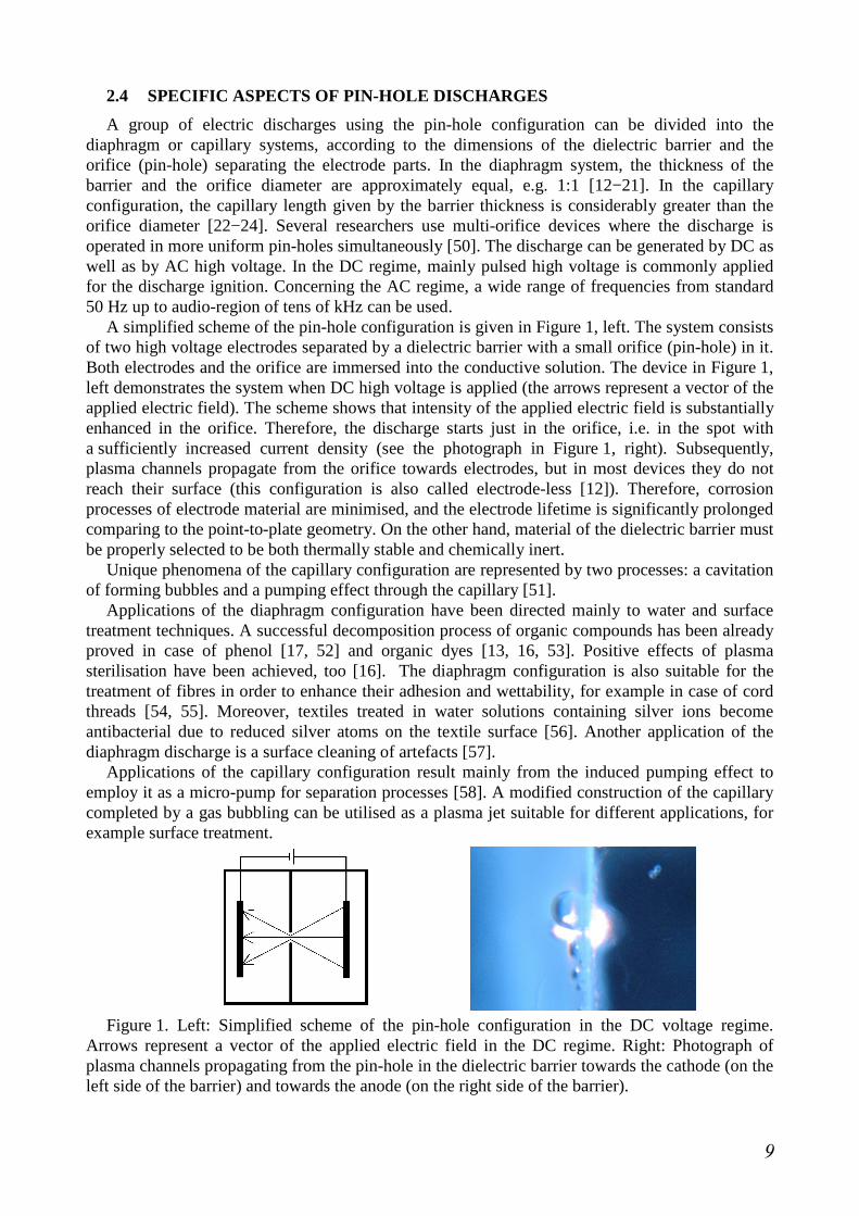
A simplified scheme of the pin-hole configuration is given in Figure 1, left. The system consists of two high voltage electrodes separated by a dielectric barrier with a small orifice (pin-hole) in it. Both electrodes and the orifice are immersed into the conductive solution. The device in Figure 1, left demonstrates the system when DC high voltage is applied (the arrows represent a vector of the applied electric field). The scheme shows that intensity of the applied electric field is substantially enhanced in the orifice. Therefore, the discharge starts just in the orifice, i.e. in the spot with a sufficiently increased current density (see the photograph in Figure 1, right). Subsequently, plasma channels propagate from the orifice towards electrodes, but in most devices they do not reach their surface (this configuration is also called electrode-less [12]). Therefore, corrosion processes of electrode material are minimised, and the electrode lifetime is significantly prolonged comparing to the point-to-plate geometry. On the other hand, material of the dielectric barrier must be properly selected to be both thermally stable and chemically inert.
Unique phenomena of the capillary configuration are represented by two processes: a cavitation of forming bubbles and a pumping effect through the capillary [51].
Applications of the diaphragm configuration have been directed mainly to water and surface treatment techniques. A successful decomposition process of organic compounds has been already proved in case of phenol [17, 52] and organic dyes [13, 16, 53]. Positive effects of plasma sterilisation have been achieved, too [16]. The diaphragm configuration is also suitable for the treatment of fibres in order to enhance their adhesion and wettability, for example in case of cord threads [54, 55]. Moreover, textiles treated in water solutions containing silver ions become antibacterial due to reduced silver atoms on the textile surface [56]. Another application of the diaphragm discharge is a surface cleaning of artefacts [57].
Applications of the capillary configuration result mainly from the induced pumping effect to employ it as a micro-pump for separation processes [58]. A modified construction of the capillary completed by a gas bubbling can be utilised as a plasma jet suitable for different applications, for example surface treatment.
Figure 1. Left: Simplified scheme of the pin-hole configuration in the DC voltage regime.
Arrows represent a vector of the applied electric field in the DC regime. Right: Photograph of plasma channels propagating from the pin-hole in the dielectric barrier towards the cathode (on the left side of the barrier) and towards the anode (on the right side of the barrier).
9

3 EXPERIMENTAL TECHNIQUES The experimental work was realised in several plasma devices (discharge reactors) based on
a similar electrode configuration (diaphragm or capillary) in a batch reactor. Constructions of the devices have been improved and adapted during the research in order to ensure requirements for particular studied processes and plasma parameters. It was possible to connect all discharge reactors to several high voltage sources providing different power supplies: DC non-pulsed, DC pulsed and AC high frequency regime. The whole experimental apparatus was completed by other components used mainly for plasma diagnostics: multi-meters, oscilloscopes and high voltage probes, spectrometers connected by an optical fibre to the reactor, high speed and ICCD cameras or a microphone.
3.1 PLASMA REACTORS
Construction of plasma reactors enabling generation of electric discharges directly in the liquid environment was one of the main parts of this work. The devices were modified and designed for various experimental conditions including a volume of the treated solution, necessity of the cooling or mixing system, fixation and changeability of particular reactor components (electrodes, dielectric barrier, etc.), types of plasma diagnostic devices connected to the reactor, etc. Each improved plasma reactor was tested at the set experimental conditions in order to estimate its optimal operation regime.
The first prototype of the discharge reactor for the plasma generation in liquids was constructed at our laboratory in 2001 [59], and it has been used in experiments up to now. Its scheme and photograph are shown in Figure 2. The main body of the reactor is made of polycarbonate (the thickness of 16 mm), and it can be filled by water solution of total volume varied from 3 to 4 litres. This reactor uses the pin-hole configuration with a replaceable dielectric barrier. The barrier material has to be both chemically inert and thermally stable. The most used ones are PET and Shapal-MTM ceramics [60]. Some other materials were studied in [61], too. The diaphragm thickness can vary from 0.05 up to 5 mm. The orifice diameter can vary from 0.2 to several millimetres as well, depending on the barrier thickness. One central orifice is usually used in the diaphragm. However, it is possible to make more identical pin-holes in the diaphragm. Planar high voltage electrodes (5×12 cm) are installed in a fixed distance of 2 cm with respect to the dielectric barrier. Electrode material used in experiments is mainly stainless steel or platinum (titanium electrodes covered by a 0.25 µm platinum layer). The device is equipped with a mixing system, and with two batch cooling boxes containing icy water. The reactor is covered by a security top without which it is not possible to generate the discharge.
Figure 2. Scheme (left) and photograph (right) of the prototype discharge reactor: 1 − dielectric
barrier, 2, 3 − high voltage electrodes, 4, 5 − cooling boxes, 6 − optical fibre, 7 − security pin, HV – high voltage source.
10

Next plasma reactors for the pin-hole discharge generation in water solutions were constructed on the similar basis as the first prototype device. As it has been already mentioned above, they differ mainly in the volume of the treated solution and in the possibility of connected components for plasma diagnostics. The most specific devices are shown in Figure 3.
Figure 3. Specific plasma reactors for plasma diagnostics: reactor for ICCD imaging in the pin-
hole discharge axis (left; volume of 50 ml) and reactor for short electric measurements (right; volume of 10 ml).
3.2 PLASMA DIAGNOSTICS
Plasma generated by the electric discharge in water solutions was studied using several diagnostic methods in order to estimate important plasma parameters. Both qualitative and quantitative parameters were in the focus. The qualitative parameters included determination of various chemical species formed by the discharge in water solution, estimation of the discharge breakdown moment, identification of the discharge character (types of created plasma channels) or bubble formation. Among quantitative parameters, concentration of particular chemical species (hydrogen peroxide, hydroxyl, hydrogen and oxygen radicals, electrons, etc.), electron and rotational temperature or electron density were determined.
Estimation of the discharge breakdown moment in water solutions was carried out by electric measurements using multi-channel oscilloscopes (mostly Tektronix 1012B and 2024B or LeCroy LT374L) and standard multi-meters (METEX M-4650CR). Simultaneously, electric parameters such as breakdown voltage, current, power and their mean values were evaluated as a function of different experimental conditions.
Processes of plasma creation, propagation of plasma channels (streamers) and bubble formation were investigated visually by detailed photographs as well as by ICCD and high speed camera records. A substantial part of this research was realised in the Laboratory of Plasma Physics at Ecole Polytechnique in Paris where the ICCD camera Andor iStar with the objective Cosmicar/Pentax (TV lens 50 mm) was used.
Next method, the optical emission spectroscopy (OES), provided the detection of chemical species excited by the discharge in water solutions. From obtained emission spectra, plasma parameters such as rotational and electron temperature and electron density were estimated.
3.3 CHEMICAL ANALYSES OF TREATED SOLUTIONS
The liquid solution in which the discharge is generated must contain a sufficient amount of charged particles in order to ensure high current density for the discharge breakdown. This condition is represented by sufficient solution conductivity which optimal value is depended on the applied high voltage regime and the electrode configuration. In the case of water solutions, which are the most studied liquid systems in general, solution conductivity is adjusted by the addition of a simple inorganic electrolyte such as NaCl. Within this work, various inorganic as
11
well as organic electrolytes were used in order to adjust both initial solution conductivity and pH. Other compounds, especially on organic basis (organic dyes and humic acids), were added into the treated solution in order to study their decomposition process initiated by the discharge. Additionally, sterilisation effects of investigated plasma were studied on two selected microorganisms, spores of fungi Aspergillus niger and spores of bacteria Bacillus subtilis.
Several analytical methods were employed in order to determine chemical composition or properties of the treated solutions. In all experiments, physical properties such as conductivity, pH and temperature of the solution were observed, too.
The inductively coupled plasma (ICP) was used for both qualitative and quantitative estimation of atomic elements, especially metallic traces, contained in water solutions treated by the discharge.
The colorimetric method using a selective test titanium reagent was utilised for hydrogen peroxide estimation in water solutions. The method is based on the specific reaction of hydrogen peroxide with the test reagent forming a yellow coloured complex of pertitanic acid. Concentration of hydrogen peroxide in the complex is directly proportional to the complex absorption at 407 nm. Therefore, absorption spectrometers Unicam UV−Visible Helios Alfa or Omega were used for the hydrogen peroxide determination.
Solutions of organic compounds (dyes or humic acids) were analysed by the UV−VIS and fluorescence spectroscopy and by the HPLC−MS technique. For fluorescence analyses of humic solutions, the luminiscence spectrometer AMINCO-Bauman® Series 2 was used. Based on the ratio of the emission intensity at 470 and 400 nm, the humification index (HIX) [62] was calculated as a qualitative parameter characterising the humic solution representing the mutual content of aromatic and aliphatic components in the mixture.
The HPLC−MS analyses were ordered commercially at Povodí Moravy, s.p. Therefore, only a limited number of samples was analysed. The analyses were focused mainly on degradation products of the organic dye Direct Red 79, which was the most frequently used compound in other experiments and analyses. Devices utilised for solution analyses at Povodí Moravy, s.p. were Agilent 1200 Series for HPLC and Agilent 6410 Triple Quad for LC-MS. An electro-spray (ESI) method was used for sample ionisation.
In the case of plasma sterilisations, the evaluation of the spore concentration before and after the plasma treatment was carried out by the standard counting plate method (CFU method).
Detailed descriptions of particular experimental procedures are given in the habilitation thesis.
12

4 LIST OF PAPERS INCLUDED IN HABILITATION THESIS
[K1] Hlavatá, L., Krčma, F., Kozáková, Z. Influence of Electrode Configuration on DC Diaphragm Discharge Breakdown in Electrolyte Solution. Journal of Physics: Conference Series, 2011, 4 pages – accepted. ISSN 1742-6596
[K2] Kozáková, Z., Nejezchleb, M., Krčma, F., Halamová, I., Čáslavský, J., Dolinová, J. Removal of Organic Dye Direct Red 79 from Water Solutions by DC Diaphragm Discharge: Analysis of Decomposition Products. Desalination, 2010, vol. 258, pp. 93−99. ISSN 0011-9164
[K3] Stará, Z., Krčma, F., Procházková, J. Physical Aspects of Diaphragm Discharge Creation Using Constant DC High Voltage in Electrolyte Solution. Acta Technica CSAV, 2008, vol. 53, pp. 277−286. ISSN 0001-7043
[K4] Stará, Z., Krčma, F., Nejezchleb, M., Skalný, J. D. Influence of Solution Composition and Chemical Structure of Dye on Removal of Organic Dye by DC Diaphragm Discharge in Water Solutions. Journal of Advanced Oxidation Technologies, 2008, vol. 11, pp. 155−162. ISSN 1203-8407
[K5] Procházková, J., Stará, Z., Krčma, F. Optical Emission Spectroscopy of Diaphragm Discharge in Water Solutions. Czechoslovak Journal of Physics, 2006, vol. 56, pp. B1314−B1319. ISSN 0011-4626
[K6] Krčma, F., Stará, Z., Slavíček, P. Physical Phenomena Occurring During DC Diaphragm Discharge in Aqueous Solutions of Electrolytes. Proceedings of ESCAMPIG XVIII, 12–16 July 2006, Lecce, Italy, pp. 467–468.
[K7] Stará, Z., Krčma, F. Treatment of Humic Acids Solutions by Diaphragm Discharge, Czechoslovak Journal of Physics, 2006, vol. 56, pp. B1351−B1356. ISSN 0011-4626
[K8] Stará, Z., Krčma, F. Degradation of Organic Dyes Versus H2O2 Generation During the DC Diaphragm Discharge Treatment in Water Solutions. Acta Physica Slovaca, 2005, vol. 55, pp. 515−519. ISSN 0323-0465
[K9] Stará, Z., Krčma, F. The Study of H2O2 Generation by DC Diaphragm Discharge in Liquids. Czechoslovak Journal of Physics, 2004, vol. 54, pp. C1050−C1055. ISSN 0011-4626
13
5 OVERVIEW OF THE MOST IMPORTANT RESULTS This section presents the main results and substantial findings obtained during more than
10 year investigation focused on the electric discharges and related processes in water solutions. Studied problems are divided into three main chapters: the discharge breakdown and its diagnostics, physical and chemical processes initiated by the discharge including the formation of reactive species, and applications of the discharge in water solutions. The following chapters contain either links on selected articles in scientific journals and conference proceedings with already published results or a brief description of the substantial results which have not been published yet. The most important articles with fundamental results and conclusions are also attached in the habilitation thesis [K1−K9].
5.1 DISCHARGE BREAKDOWN AND PLASMA DIAGNOSTICS
As it was already mentioned above, ignition of the electric discharge in water solutions requires a special configuration of the plasma reactor as well as proper adjustment of experimental conditions. Both the device parameters and solution properties are important in the process of the discharge creation, and they are specific for each used system.
This part of work deals mainly with the DC non-pulsed discharge generated in the pin-hole configuration at atmospheric pressure. In additional experiments, modified DC pulsed or high frequency voltage was applied.
According to the theoretical background described in Chapter 2, the discharge ignition (breakdown) in water is represented by the ionisation of water molecules as a result of inelastic collisions with high excited electrons. The process is related to the substantial bubble formation and light emission in the form of plasma channels (streamers). Therefore, identification of the exact discharge breakdown moment can be realised by electric measurements and visual records using the high speed or ICCD camera. Estimation of the discharge breakdown by electric measurements was based on observations of the main electric parameters (voltage, current, resistance and power) in order to determine their rapid change due to the formation of ionised particles creating the plasma. Simultaneously, other important processes such as bubble formation and plasma streamers propagation were recorded by detailed imaging. Both electric measurements and detailed imaging were carried out at different discharge conditions in order to observe influence of particular experimental parameters on the studied processes, and to find out optimal conditions for the discharge operation for defined systems. Results related to these phenomena were published in several journals [K1, K3, K5, K9] and [63, 64] as well as conference proceedings [65−70] (a list of selected contributions).
Plasma diagnostics was completed by the optical emission spectroscopy (OES) in order to identify reactive species produced by the discharge in water solutions, determine quantity of particular species in the dependence on experimental conditions, and calculate important plasma parameters such as electron and rotational temperature, electron density, etc. Results related to plasma diagnostics by OES were published in journals [K5] and [63, 64, 71] as well as conference proceedings [66, 68, 72−76] (a list of selected contributions).
5.1.1 Electric measurements
The electric discharge ignition in water solutions was investigated in details for the pin-hole configuration and application of DC non-pulsed voltage. Typical results of electric measurements are presented for the discharge ignition in Na3PO4 electrolyte with initial conductivity of 500 µS/cm. Influence of different experimental conditions (solution composition and conductivity, reactor configuration, applied voltage regime, etc.) on the discharge breakdown is discussed below. Both time resolved and static current-voltage characteristics were employed to observe the
14

main electric parameters (discharge voltage, current, power and resistance) during the ignition process. Additionally, sound produced by bubble formation and light emitted by excited species in the discharge was recorded, too.
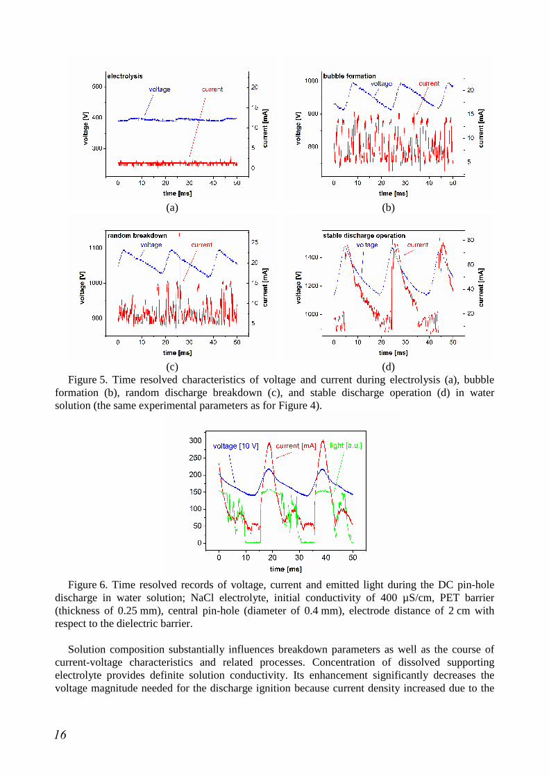
A typical current-voltage characteristic of the DC pin-hole discharge generated in water solution is demonstrated in Figure 4. This curve could be divided into three parts. Increasing the applied DC voltage, measured current slowly increased as well. During this starting part, only electrolysis takes place in the system, and the electrolyte solution is heated by the passing current (Joule effect). Going above the voltage of hundreds volts, the first significant breakpoint appears in the curve – mean current markedly arises. According to the time resolved characteristics (Figure 5, b), it can be assumed that this moment is related to the substantial creation of bubbles formed by the evaporating solution. Further enhancement of voltage provides only a small current increase until the second remarkable breakpoint is observed. From this moment, current is rapidly arising with only a small voltage enhancement. This second breakpoint is assumed to be the discharge breakdown moment which has been also confirmed by recorded light emission [63].
Selected time resolved characteristics of voltage and current, which were recorded during the main discharge phases, are demonstrated in Figure 5. At least three sections can be distinguished before and during the discharge ignition: an electrolytic part, bubble formation and stable discharge operation. During electrolysis at lower applied voltage up to 700 V, no significant peaks appears in regular voltage and current oscillations (Figure 5, a). Voltage oscillations are related to the HV source construction, and they have no significant influence on the observed phenomena. At higher applied voltage (700−1200 V), remarkably higher oscillations of both current and voltage are recorded (Figure 5, b). This phenomenon is related to the bubble formation due to the intensive solution heating by passing current. No light emission is observed during this period. Further enhancement of applied voltage provides irregular sharp current peaks that appear in the record (Figure 5, c). This phenomenon is related to random breakdown of vapour bubble, and short peaks of emitted light are recorded, too [63]. When breakdown voltage is overstepped (beyond 1200 V), the discharge is ignited in the pin-hole, and regular peaks of current (Figure 5, d) are recorded as well as the intensive light emission (Figure 6).
Figure 4. Typical A−V characteristic of the DC pin-hole discharge in water solution; Na3PO4
electrolyte, initial conductivity of 500 µS/cm, PET barrier (thickness of 0.25 mm), central pin-hole (diameter of 0.4 mm), electrode distance of 2 cm with respect to the dielectric barrier. Points (a)−(d) correspond to Figure 5.
15
(a) (b)
(c) (d) Figure 5. Time resolved characteristics of voltage and current during electrolysis (a), bubble
formation (b), random discharge breakdown (c), and stable discharge operation (d) in water solution (the same experimental parameters as for Figure 4).
Figure 6. Time resolved records of voltage, current and emitted light during the DC pin-hole
discharge in water solution; NaCl electrolyte, initial conductivity of 400 µS/cm, PET barrier (thickness of 0.25 mm), central pin-hole (diameter of 0.4 mm), electrode distance of 2 cm with respect to the dielectric barrier.
Solution composition substantially influences breakdown parameters as well as the course of
current-voltage characteristics and related processes. Concentration of dissolved supporting electrolyte provides definite solution conductivity. Its enhancement significantly decreases the voltage magnitude needed for the discharge ignition because current density increased due to the
16
higher concentration of charged particles in the solution. Further, solution conductivity also affects the other parts of A−V characteristics, especially the bubble formation. This process appears at lower applied voltage when higher solution conductivity is used. On the other hand, an influence of electrolyte itself on the breakdown and electric characteristics is not so obvious. More details about effects of solution properties on the discharge breakdown can be found in [K1, K3] and [63, 64, 66, 67].
Following parameters of the discharge reactor were changed in order to estimate an influence of the configuration on the discharge breakdown and related processes: electrode distance, pin-hole diameter, thickness of the dielectric barrier (defining the diaphragm or capillary system) and applied high voltage regime. Increasing the electrode distance with respect to the dielectric barrier, higher voltage must be applied for the discharge ignition. However, the shift of electrodes does not affect the other processes recorded in the A−V curve, e.g. the electrolysis and the bubble formation. Concerning the pin-hole diameter, its influence on the observed processes is not so remarkable in the studied range of dimensions. But a serious extension of the pin-hole requires significantly higher voltage applied for the discharge ignition. On the other hand, thickness of the dielectric barrier plays an important role in the discharge breakdown as well as in the process of bubble formation. Thicker barriers used in the capillary configuration require application of higher voltage for the discharge ignition than thinner diaphragm systems. However, discharge current seems to be independent on the barrier dimensions. More details about effects of the reactor configuration on the discharge breakdown and bubble formation can be found in [K1] and [65, 77].
The use of the capillary configuration causes an intensive bubble formation in and around the pin-hole. This phenomenon lead to the cavitation effect, and it is accompanied by a strong sound signal. Peaks of the recorded sound signal correspond to the peaks of voltage and current which are related to the discharge ignition in the forming bubbles (as it was described by the thermal theory in Chapter 2). The same effect was observed for three voltage regimes applied in the experimental series: DC non-pulsed, modified DC pulsed and high frequency voltage in the audiofrequency range. These quite recent results were published in [70].
5.1.2 Visual records of plasma streamers and bubble formation
The visual observation of the discharge generation in water solutions was realised in details for the pin-hole configuration and mostly for the application of DC non-pulsed voltage. Classic photographs, high speed camera records and ICCD imaging were employed in order to study plasma streamers propagation as well as bubble formation in the pin-hole. Due to relatively higher demands on the imaging quality (i.e. detailed photographs with high resolution), the related results were published quite recently in [69, 70]. Preliminary results are discussed in the habilitation thesis.
Confirmation of breakdown theories
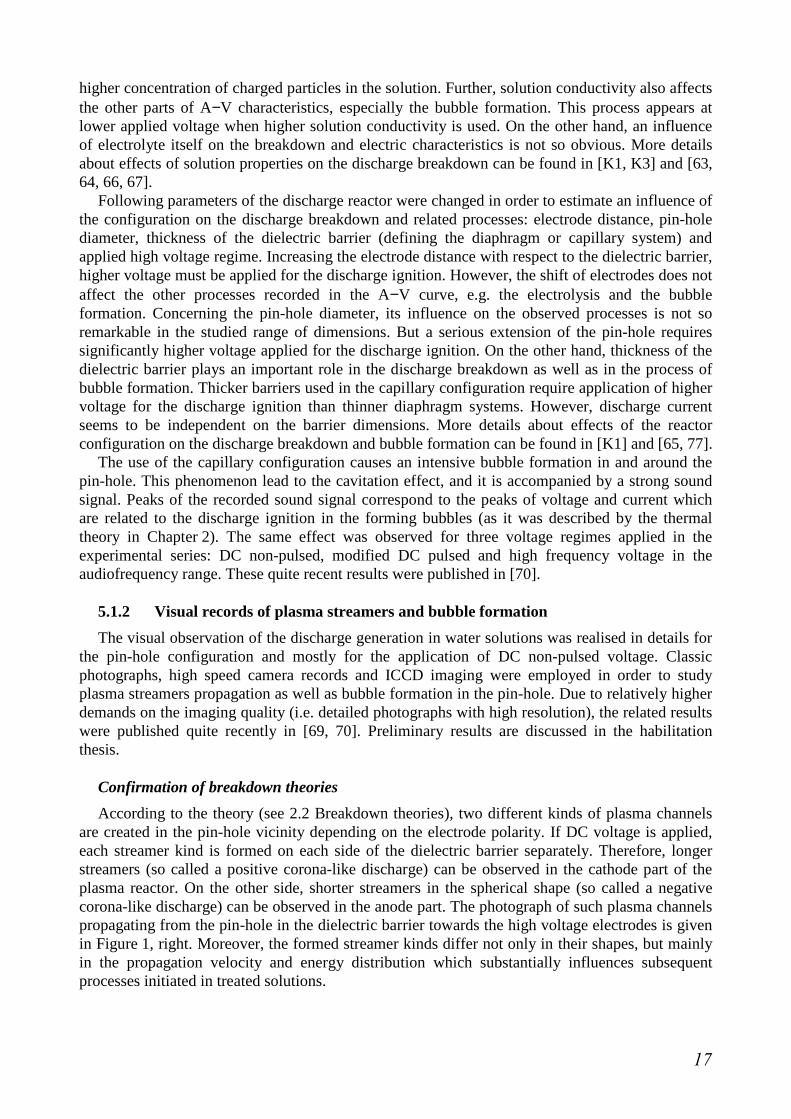
According to the theory (see 2.2 Breakdown theories), two different kinds of plasma channels are created in the pin-hole vicinity depending on the electrode polarity. If DC voltage is applied, each streamer kind is formed on each side of the dielectric barrier separately. Therefore, longer streamers (so called a positive corona-like discharge) can be observed in the cathode part of the plasma reactor. On the other side, shorter streamers in the spherical shape (so called a negative corona-like discharge) can be observed in the anode part. The photograph of such plasma channels propagating from the pin-hole in the dielectric barrier towards the high voltage electrodes is given in Figure 1, right. Moreover, the formed streamer kinds differ not only in their shapes, but mainly in the propagation velocity and energy distribution which substantially influences subsequent processes initiated in treated solutions.
17

Visual records were also employed in order to confirm the thermal (bubble) or electron breakdown theory of the pin-hole discharge in water solutions. As it has been already mentioned, formation of bubbles accompanied the discharge in the pin-hole before and after its breakdown due to the intensive heating of the solution (Joule heating). Detailed images of the ICCD camera gave a proper in look into this phenomenon. In general, two modes of the pin-hole discharge were observed [70]. Both situations are captured by images in Figure 7. The left picture shows the formation of bubbles in the pin-hole (a horizontal white stripe in the middle of the image represents the dielectric barrier). After their creation in the orifice, they are dragged into the solution volume. Moreover, the appearance of plasma streamers in the bubble below the dielectric barrier is clearly seen, too. On the other hand, the right picture shows the long plasma channels propagating through the solution towards the electrode (cathode) outside any bubble. Therefore, these photos confirm both the thermal and electron theory described above. Primary, the discharge breakdown appears in the gas phase of water vapour (in the bubble), and then plasma channels spread out by the dissociation and ionisation of water molecules into the solution volume.
Figure 7. ICCD images of micro-bubble formation and plasma streamers in the bubble (left)
and plasma streamers in the cathode part (right); NaCl electrolyte, initial conductivity of 1000 µS/cm (left) and 300 µS/cm (right), ceramic barrier (thickness of 0.3 mm), central pin-hole (diameter of 0.3 mm).
5.1.3 Plasma diagnostics by optical emission spectroscopy
Diagnostics of plasma generated by electric discharge in water solutions was completed by the optical emission spectroscopy (OES). Both qualitative and quantitative determination of reactive species produced by the discharge in water solutions and their dependence on experimental conditions is discussed in Chapter 5.2.2. Based on recorded emission spectra, important plasma parameters such as rotational temperature, electron density and electron temperature were calculated and evaluated as a function of different experimental conditions (applied power, solution conductivity or voltage polarity). Results related to this topic were preliminary published in [K5] and quite recently in [72].
A typical emission spectrum of the DC pin-hole discharge obtained in the water solution of NaCl electrolyte is shown in Figure 8. The presented spectrum confirms the formation of OH radicals (emission bands around 310 nm) as well as atomic hydrogen (emission lines Hα at 656 nm, Hβ at 486 nm, and Hγ at 434 nm). Additionally, spectral lines of elements dissolved in the treated solutions were detected, too. The spectrum contains a strong emission doublet of sodium atoms (589 nm) coming from the supporting NaCl electrolyte. Consequently, the detailed spectra of selected species were used for the calculation of plasma parameters such as rotational temperature (OH A-X 0-0 band at 310 nm), and electron density (Hβ line at 486 nm).
18
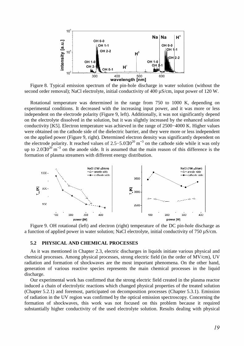
Figure 8. Typical emission spectrum of the pin-hole discharge in water solution (without the
second order removal); NaCl electrolyte, initial conductivity of 400 µS/cm, input power of 120 W. Rotational temperature was determined in the range from 750 to 1000 K, depending on
experimental conditions. It decreased with the increasing input power, and it was more or less independent on the electrode polarity (Figure 9, left). Additionally, it was not significantly depend on the electrolyte dissolved in the solution, but it was slightly increased by the enhanced solution conductivity [K5]. Electron temperature was achieved in the range of 2500−4000 K. Higher values were obtained on the cathode side of the dielectric barrier, and they were more or less independent on the applied power (Figure 9, right). Determined electron density was significantly dependent on the electrode polarity. It reached values of 2.5−5.0⋅1020 m−3 on the cathode side while it was only up to 2.0⋅1020 m−3 on the anode side. It is assumed that the main reason of this difference is the formation of plasma streamers with different energy distribution.
Figure 9. OH rotational (left) and electron (right) temperature of the DC pin-hole discharge as
a function of applied power in water solution; NaCl electrolyte, initial conductivity of 750 µS/cm. 5.2 PHYSICAL AND CHEMICAL PROCESSES
As it was mentioned in Chapter 2.3, electric discharges in liquids initiate various physical and chemical processes. Among physical processes, strong electric field (in the order of MV/cm), UV radiation and formation of shockwaves are the most important phenomena. On the other hand, generation of various reactive species represents the main chemical processes in the liquid discharge.
Our experimental work has confirmed that the strong electric field created in the plasma reactor induced a chain of electrolytic reactions which changed physical properties of the treated solution (Chapter 5.2.1) and foremost, participated on decomposition processes (Chapter 5.3.1). Emission of radiation in the UV region was confirmed by the optical emission spectroscopy. Concerning the formation of shockwaves, this work was not focused on this problem because it required substantially higher conductivity of the used electrolyte solution. Results dealing with physical
19
processes and changes of physical properties of the water solutions treated by the discharge were published in several journals [K7, K9] and [78, 79] as well as conference proceedings [K6] and [75, 80, 81] (a list of selected contributions). Results dealing with chemical processes which lead to the formation of reactive species are presented in Chapter 5.2.2. They are focused on the detection of radicals (especially, OH, H and O radicals) [K5; 63, 64, 66, 68, 73, 74−76], production of hydrogen peroxide [K8, K9; 63, 64, 68, 75, 76, 79, 80], and on the emission of metals contained in the treated solution [K6, K7; 63, 64, 76].
5.2.1 Changes of solution properties during the discharge treatment
Production of a number of reactive chemical species induced by the electric discharge generation in water solutions essentially affected physical properties of the treated solution such as conductivity and pH. Moreover, solution temperature is also changing during the discharge operation due to significantly increased current density. Therefore, the main three physical parameters (conductivity, pH and temperature) were precisely measured during all experiments.
In general, solution conductivity was significantly enhanced by the discharge operation at all applied high voltage regimes (DC or HF). The conductivity increase was dependent on the electrode polarity when the DC regime was used, and on the kind of electrolyte used for the adjustment of the initial solution conductivity. More details about this parameter are discussed in [K6, K7, K9; 75, 79].
Changes of solution pH during the pin-hole discharge operation in water solutions were more complicated as well as interesting. This parameter was dramatically influenced by the electrode polarity in the plasma device because of electrochemical reactions induced on the electrodes. Oxidation reactions on the anode produced the increased amount of hydrogen cation which significantly decreased pH to strongly acidic values. On the other hand, reduction reactions on the cathode provided the increase of pH up to basic conditions. Based on these processes, pH progress during the discharge treatment depended on the used plasma device as well as voltage regime. Moreover, problems of pH play an important role in consequent chemical processes initiated by the discharge in water solutions. Therefore, a special attention to the pH effect must be taken into account during the discharge applications. More details about pH changes and its influence on studied processes can be found in [K6, K7; 78, 80].
Solution temperature was enhanced by the discharge operation in the dependence on the set conditions. In case of the DC discharges, current density was high and thus the solution heating was more intensive. If the standard batch device (volume of 3 L) without the cooling system was used, temperature gradient of 10−15 °C per 20 minutes was observed, depending on the mean input power (150−250 W). Therefore, the cooling system was necessary to apply for longer experiments. In case of the HF discharges, the current stress was not so high and thus temperature reached only slightly enhanced values of approximately 2−3 °C [80]. Contrary to the applied power, no influence of solution composition and initial conductivity on the temperature progress was observed.
5.2.2 Formation of chemical species
Electric discharges generated in water solutions initiate a chain of various chemical reactions that produce a number of reactive chemical species. Processes such as excitation, ionisation and dissociation of water molecules lead to the formation of radicals (hydroxyl, hydrogen, oxygen, etc.), ions and molecules (hydrogen peroxide) with high oxidation potentials.
Detection of particles which emit light in the UV and visible range of wavelength (200−1000 nm) was carried out by the optical emission spectroscopy (OES). Especially radicals (OH, H and O) and metallic traces (alkaline metals such as Na, K, Li, etc.) were detected both qualitatively and quantitatively. A typical overview spectrum of the DC pin-hole discharge in
20

NaCl solution is demonstrated in Figure 8. It clearly shows emission atomic lines of hydrogen (Hα: 656 nm, Hβ: 486 nm and Hγ: 434 nm) and OH bands (the first order: 305−325 nm and the second order: 610−650 nm). Oxygen atomic lines (777 nm and 843 nm) were detected as well. Besides these particles coming from water molecules, emission lines of elements (Na doublet: 589 nm, Cl: 820 nm) contained in the electrolyte were identified, too. A spectral line of iron (Fe: 528 nm) appeared in the spectrum due to the use of stainless steel electrodes. Additional detection of metal elements in the treated solution was realised by the inductively coupled plasma (ICP). Besides excited species and metal elements, hydrogen peroxide as one of final molecules produced by the discharge in water was estimated by the simple colorimetric method using the specific titanium test reagent (for details, see Chapter 3.3). Results on the main chemical species (OH radicals, hydrogen peroxide and metal elements) are discussed in the following subchapters.
OH radicals
Primary hydroxyl radicals are formed by the dissociation of water molecules induced by a direct impact of high energy electrons (e−*) in the discharge plasma [46]:
−∗− +⋅+⋅→+ eHOHeOH 2 . (1)
Therefore in water solutions, hydroxyl radicals are always produced by the discharge operation. However, their quantity is dependent on various experimental conditions. Due to the strong emission in the spectral range from 305 to 325 nm (see Figure 8), OH radicals can be easily detected from emission spectra recorded over the mentioned region. For further interpretation and experiment evaluation, an integral OH emission intensity was calculated over the range of 306.5−318.0 nm. Such obtained value was set as a quantitative parameter of the discharge operation. This work studied influence of different discharge conditions on the OH emission in order to estimate optimal parameters for the discharge operation in particular configurations.
The most important parameter affecting the OH emission was the input high voltage. Increasing the applied power, emission of hydroxyl radicals increased as well. In case of the DC regime, the OH emission intensity was also dependent on the electrode polarity. A slightly higher intensity was recorded on the side with the cathode where longer plasma streamers were created. On the other hand, other parameters such as solution composition or its conductivity seems to have no substantial effect on the emission of hydroxyl radicals. Results related to the detection of OH radicals and optical emission spectroscopy in general were published in [K5; 63, 64, 66, 68, 73−76].
Hydrogen peroxide
Hydrogen peroxide is one of the terminal compounds formed by the electric discharge in water solutions. It is created by the recombination of hydroxyl radicals [46]:
22OHOHOH →⋅+⋅ . (2)
However, there are more possible reactions leading to hydrogen peroxide formation in water. On the other hand, several processes cause its decomposition back to hydrogen radicals. Especially, photolysis (exposition by UV light), high temperature (above 30 °C) and catalysis by ferrous ions (so called Fenton reaction) are the main reverse processes [82].
Based on theoretical assumptions (for details, see the habilitation thesis), hydrogen peroxide production was expected to be linear during the discharge operation. Therefore, hydrogen peroxide concentration and its net production rate, respectively, were assumed to be comparable quantitative parameters of the discharge operation. Within this work, they were evaluated as a function of various experimental conditions (discharge configuration, solution properties, etc.).
21
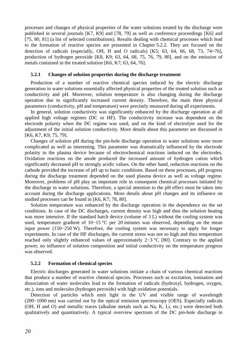
Hydrogen peroxide production was influenced especially by the applied voltage regime whereas the polarity of electrodes played a very important role. When DC high voltage was applied, H2O2 formation was significantly higher in the cathode part of the reactor while H2O2 concentration was only negligible in the anode part. A typical evaluation of hydrogen peroxide concentration during the DC discharge in the pin-hole configuration is presented in Figure 10. In case of the HF discharges, production of hydrogen peroxide was equal in both electrode parts, and its net rate corresponded to the half value of the rate in the DC cathode part. In all experiments, hydrogen peroxide concentration increased linearly during the discharge. This fact allowed the subsequent calculation of the net production rate of hydrogen peroxide, and confirmed the zero order reaction of the H2O2 formation.
Figure 10. Comparison of hydrogen peroxide formation in two electrode parts during the DC
pin-hole discharge in water solution; NaCl electrolyte, initial conductivity of 500 µS/cm, PET diaphragm (thickness of 0.25 mm), central pin-hole (diameter of 0.4 mm), electrode distance of 2 cm with respect to the dielectric barrier, input power of 200 W.
Concerning other experimental parameters and their influence on hydrogen peroxide formation,
mainly input power and solution properties (initial conductivity and pH) substantially affected the production rates. Configuration of the dielectric barrier (material, thickness and pin-hole diameter) must be also appropriately set up because it strongly influenced the discharge breakdown itself. Some other experimental parameters such as electrolyte kind, electrode material or a number of pin-holes in the dielectric barrier seemed to have no significant effect on hydrogen peroxide formation. Fundamental results focusing on hydrogen peroxide formation and the discharge efficiency at various experimental conditions were published in following journals [K8, K9; 63, 64, 79] and conference proceedings [68, 75, 76, 80].
Detection of metals
The origin of metal elements in the treated solution had two sources. The first one was a dissolved supporting electrolyte which was used for the adjustment of the initial solution conductivity. Especially, alkaline metals (sodium, potassium, lithium, etc.) and some other elements (chlorine, phosphorus) got into the solution by this way. Next source of metal elements was represented by metal components of the discharge reactor which were loaded by high current density. Electrochemical processes induced a release of metal elements mainly from less inert electrodes. For example, iron and chromium were the main elements in case of stainless steel electrodes.
Two analytical methods were employed for the detection of metals in the treated solution. The inductively coupled plasma (ICP) was used for the analysis after the discharge operation. Especially, those traces released from the stainless steel parts of the reactor (Fe, Cr) have been
22
determined. Nevertheless, other elements originating in the dissolved electrolyte (Na, P) were detected as well [K6; 76].
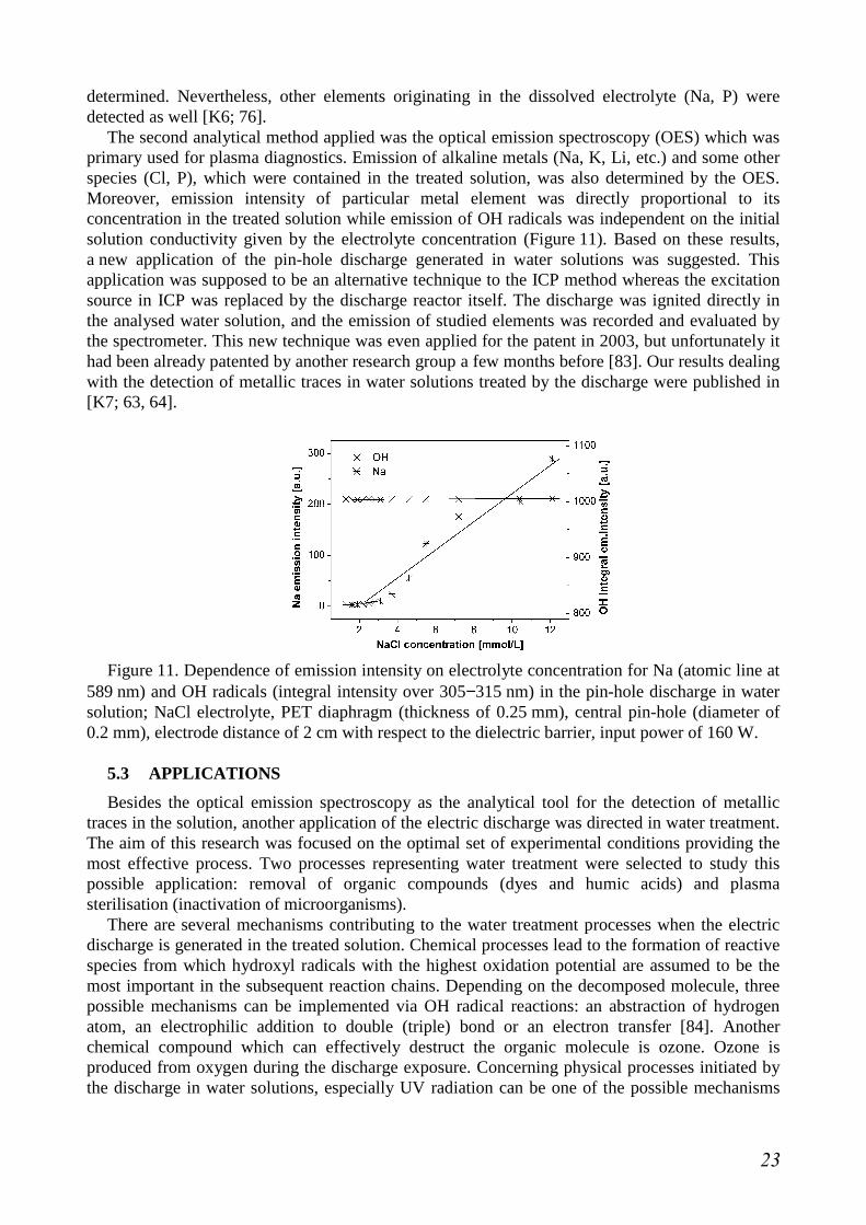
The second analytical method applied was the optical emission spectroscopy (OES) which was primary used for plasma diagnostics. Emission of alkaline metals (Na, K, Li, etc.) and some other species (Cl, P), which were contained in the treated solution, was also determined by the OES. Moreover, emission intensity of particular metal element was directly proportional to its concentration in the treated solution while emission of OH radicals was independent on the initial solution conductivity given by the electrolyte concentration (Figure 11). Based on these results, a new application of the pin-hole discharge generated in water solutions was suggested. This application was supposed to be an alternative technique to the ICP method whereas the excitation source in ICP was replaced by the discharge reactor itself. The discharge was ignited directly in the analysed water solution, and the emission of studied elements was recorded and evaluated by the spectrometer. This new technique was even applied for the patent in 2003, but unfortunately it had been already patented by another research group a few months before [83]. Our results dealing with the detection of metallic traces in water solutions treated by the discharge were published in [K7; 63, 64].
Figure 11. Dependence of emission intensity on electrolyte concentration for Na (atomic line at
589 nm) and OH radicals (integral intensity over 305−315 nm) in the pin-hole discharge in water solution; NaCl electrolyte, PET diaphragm (thickness of 0.25 mm), central pin-hole (diameter of 0.2 mm), electrode distance of 2 cm with respect to the dielectric barrier, input power of 160 W.
5.3 APPLICATIONS
Besides the optical emission spectroscopy as the analytical tool for the detection of metallic traces in the solution, another application of the electric discharge was directed in water treatment. The aim of this research was focused on the optimal set of experimental conditions providing the most effective process. Two processes representing water treatment were selected to study this possible application: removal of organic compounds (dyes and humic acids) and plasma sterilisation (inactivation of microorganisms).
There are several mechanisms contributing to the water treatment processes when the electric discharge is generated in the treated solution. Chemical processes lead to the formation of reactive species from which hydroxyl radicals with the highest oxidation potential are assumed to be the most important in the subsequent reaction chains. Depending on the decomposed molecule, three possible mechanisms can be implemented via OH radical reactions: an abstraction of hydrogen atom, an electrophilic addition to double (triple) bond or an electron transfer [84]. Another chemical compound which can effectively destruct the organic molecule is ozone. Ozone is produced from oxygen during the discharge exposure. Concerning physical processes initiated by the discharge in water solutions, especially UV radiation can be one of the possible mechanisms
23
leading to the compound decomposition as well as to the inactivation of microorganisms. If the DC voltage regime is applied, a substantial effect of electrochemical reactions must be taken into account, too. In case of sterilisation processes, the effect of temperature is also important. And finally, formation of shockwaves appears in the capillary configuration.
Results presented in the habilitation thesis are divided, according to the studied water contaminant, on decomposition of organic compounds (dyes [K2, K4, K8; 53, 63, 64, 68, 78, 81, 85] and humic acids [K7; 78, 86]) and plasma sterilisations [87]. Further, results obtained by the treatment of dye solutions are focused both on the total effect of the discharge and on the partial contributions of individual degradation mechanisms (electrolysis in the DC regime, UV irradiation and ozone treatment) [K4, K8; 53, 81, 85, 88, 89].
5.3.1 Decomposition of organic compounds
Water solutions containing the selected organic compound were treated in the plasma reactor with the pin-hole configuration using mostly DC non-pulsed high voltage in order to observe the decomposition process with respect to the electrode polarity simultaneously. Variable experimental parameters which influence on the decomposition process was studied were as follows: applied high voltage (character, magnitude and polarity), structure and initial concentration of organic compound and solution properties (conductivity, pH and kind of supporting electrolyte). Samples were primary analysed by the absorption spectroscopy in the UV−VIS region (250−700 nm). Further, the fluorescence spectroscopy and HPLC−MS technique were employed for the product analyses.
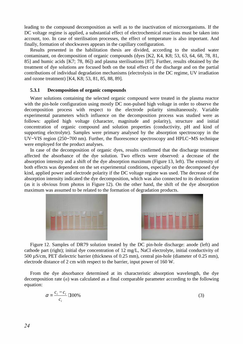
In case of the decomposition of organic dyes, results confirmed that the discharge treatment affected the absorbance of the dye solution. Two effects were observed: a decrease of the absorption intensity and a shift of the dye absorption maximum (Figure 13, left). The extensity of both effects was dependent on the set experimental conditions, especially on the decomposed dye kind, applied power and electrode polarity if the DC voltage regime was used. The decrease of the absorption intensity indicated the dye decomposition, which was also connected to its decoloration (as it is obvious from photos in Figure 12). On the other hand, the shift of the dye absorption maximum was assumed to be related to the formation of degradation products.
Figure 12. Samples of DR79 solution treated by the DC pin-hole discharge: anode (left) and
cathode part (right); initial dye concentration of 12 mg/L, NaCl electrolyte, initial conductivity of 500 µS/cm, PET dielectric barrier (thickness of 0.25 mm), central pin-hole (diameter of 0.25 mm), electrode distance of 2 cm with respect to the barrier, input power of 160 W.
From the dye absorbance determined at its characteristic absorption wavelength, the dye
decomposition rate (α) was calculated as a final comparable parameter according to the following equation:
%100⋅−
=i
ti
c
ccα (3)
24
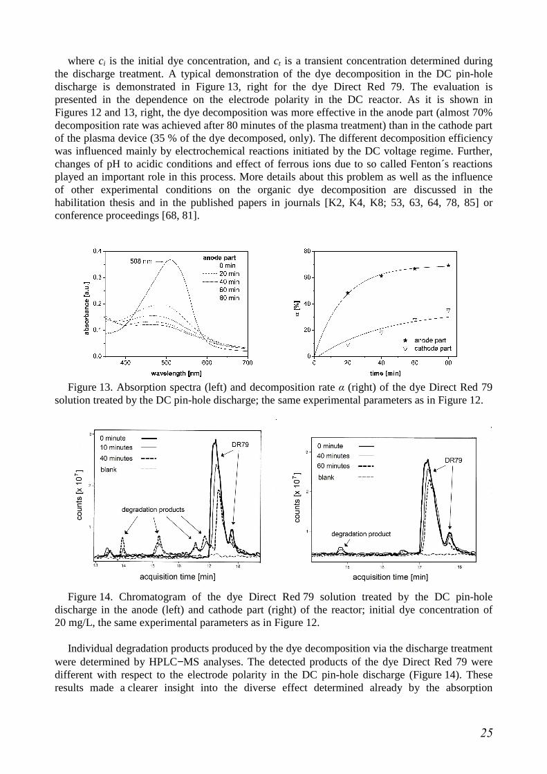
where ci is the initial dye concentration, and ct is a transient concentration determined during the discharge treatment. A typical demonstration of the dye decomposition in the DC pin-hole discharge is demonstrated in Figure 13, right for the dye Direct Red 79. The evaluation is presented in the dependence on the electrode polarity in the DC reactor. As it is shown in Figures 12 and 13, right, the dye decomposition was more effective in the anode part (almost 70% decomposition rate was achieved after 80 minutes of the plasma treatment) than in the cathode part of the plasma device (35 % of the dye decomposed, only). The different decomposition efficiency was influenced mainly by electrochemical reactions initiated by the DC voltage regime. Further, changes of pH to acidic conditions and effect of ferrous ions due to so called Fenton´s reactions played an important role in this process. More details about this problem as well as the influence of other experimental conditions on the organic dye decomposition are discussed in the habilitation thesis and in the published papers in journals [K2, K4, K8; 53, 63, 64, 78, 85] or conference proceedings [68, 81].
Figure 13. Absorption spectra (left) and decomposition rate α (right) of the dye Direct Red 79
solution treated by the DC pin-hole discharge; the same experimental parameters as in Figure 12.
Figure 14. Chromatogram of the dye Direct Red 79 solution treated by the DC pin-hole
discharge in the anode (left) and cathode part (right) of the reactor; initial dye concentration of 20 mg/L, the same experimental parameters as in Figure 12.
Individual degradation products produced by the dye decomposition via the discharge treatment
were determined by HPLC−MS analyses. The detected products of the dye Direct Red 79 were different with respect to the electrode polarity in the DC pin-hole discharge (Figure 14). These results made a clearer insight into the diverse effect determined already by the absorption
25
spectroscopy (i.e. the shift of the dye maximal absorption and the polarity influence). Detailed discussion on the HPLC−MS analyses of the treated dye solutions are presented in [K2].
When comparing formation of hydrogen peroxide and the dye decomposition in the DC pin-hole discharge, the effect was totally different with respect to the electrode polarity. While the production of hydrogen peroxide was significantly higher in the cathode part of the discharge reactor, the dye decomposition was more effective in the anode part. More details about this phenomenon are discussed in [K8; 63, 64, 68, 79].
In case of the discharge treatment focused on water solutions containing mixtures of humic acids (HA), the treatment had no remarkable affect at the studied experimental conditions. As well as in case of organic dyes, HA decomposition was higher in the anode part of the plasma reactor when the DC voltage regime was used. However, the concentration decrease was not so intensive comparing to the dye decomposition, although it could be enhanced by the increased input power. Based on fluorescence spectra recorded over the range of 350−700 nm, the humification index (HIX) indicating the mutual ratio of aromatic and aliphatic compounds in the solution was calculated. Evaluation of this index during the treatment revealed a partial transformation of aromatic compounds from the mixture to aliphatic ones. The main conclusions including effects of selected experimental parameters on the process (input power, solution pH and conductivity) were published in [K7; 78, 86]. However, it was assumed that this application was not sufficiently effective for further development. Therefore, next research is focused on other applications.
5.3.2 Plasma sterilisations
The application of the electric discharge in water solutions as a tool of plasma sterilisation was studied for the DC non-pulsed regime in the pin-hole configuration. Two microorganisms (Aspergillus niger and Bacillus subtilis) were selected as model contaminants. The evaluation of the sterilisation effect was realised by the cultivation of taken samples and subsequent calculation of colony forming units (CFU method) which survived the treatment. Results were compared for different experimental conditions such as the applied input power, exposure time and electrode polarity. In general, the increased input power as well as longer treatment time led to the enhancement of the discharge sterilisation effect. On the other hand, the electrode polarity did not seem to have any influence on the sterilisation process.
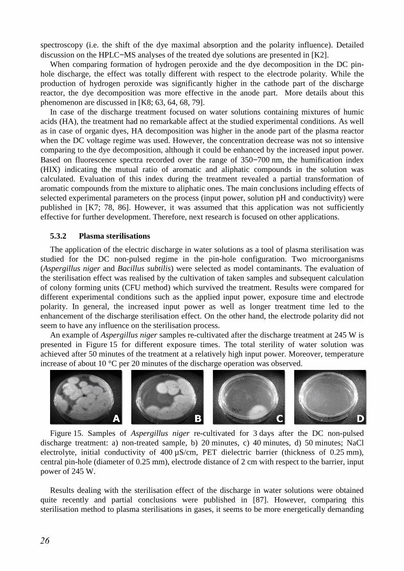
An example of Aspergillus niger samples re-cultivated after the discharge treatment at 245 W is presented in Figure 15 for different exposure times. The total sterility of water solution was achieved after 50 minutes of the treatment at a relatively high input power. Moreover, temperature increase of about 10 °C per 20 minutes of the discharge operation was observed.
Figure 15. Samples of Aspergillus niger re-cultivated for 3 days after the DC non-pulsed
discharge treatment: a) non-treated sample, b) 20 minutes, c) 40 minutes, d) 50 minutes; NaCl electrolyte, initial conductivity of 400 µS/cm, PET dielectric barrier (thickness of 0.25 mm), central pin-hole (diameter of 0.25 mm), electrode distance of 2 cm with respect to the barrier, input power of 245 W.
Results dealing with the sterilisation effect of the discharge in water solutions were obtained
quite recently and partial conclusions were published in [87]. However, comparing this sterilisation method to plasma sterilisations in gases, it seems to be more energetically demanding
26
because higher input power as well as treatment time is required to achieve the total sterility of water. Thus it was assumed that the tested plasma device was not convenient for this application at the set experimental conditions.
5.3.3 Effects of electrolysis, UV radiation and ozone
Plasma treatment of water solutions containing organic compounds is a complex chain of chemical mechanisms leading to the decomposition of the target molecule. Besides the attack of hydroxyl radicals coming from the dissociation and ionisation of water molecules by the discharge, other effects can also contribute to the degradation process. This work was focused on electrochemical oxidation in the DC discharge, UV radiation and the effect of ozone, which can be formed from the dissolved oxygen in the solution.
If the DC high voltage was applied to the plasma reactor with separated electrode parts, the increased current density (mean discharge current of 100−200 mA) induced electrochemical reactions that substantially influence the subsequent initiated process. Therefore, special sets of experiments focused on the pure electrolytic reactions in water solutions containing selected organic dyes were carried out. To conclude results obtained from these experiments, it was assumed that the process of electrolysis had a substantial effect on the dye decomposition in the DC regime. However, it was highly dependent on the molecule structure of the particular dye. Likewise, energetic efficiency evaluated for each studied dye was also significantly different. Thus, the profitability of the treatment should be solved with respect to the particular dye. More details about electrolytic influence on the studied processes are described in the habilitation thesis and in the published papers [K4, K8; 53, 81, 85, 88, 89].
Among physical processes initiated by the electric discharge in water solutions, UV radiation is one of those which can contribute to the dye decomposition within the discharge treatment. Mainly emission of OH radicals and other species in the UV region might be effective in this process. It was proved by a special set of experiments that the exposition of the dye solution to the UV light led to its decomposition. Nevertheless, comparing to the pin-hole discharge represented as the UV source it can be concluded that the contribution of the UV radiation to the dye decomposition by the discharge was only negligible. The reason was the mutual size of the UV sources because the discharge emission region was smaller by approximately three orders than the UV sources used in the special set of experiments. Moreover, UV radiation intensity of the discharge itself was also much lower than the standard UV sources. More details about this problem are described in the habilitation thesis and in [89].
Ozone is generated from oxygen molecules by the electric discharge operation. In water solution, dissolved oxygen molecules are presented according to the temperature and pressure above the surface or oxygen can be let bubbled through the solution. These processes can lead to the ozone formation and thus, this work investigated its possible effect on the dye solution. For the special set of experiments, a commercial ozonizer was used. The obtained results show that this treatment was very fast and effective independently on the tested organic dye [89]. However, concerning the contribution of ozone effect to the total discharge activity in the dye solution, it did not seem to be a great deal. The ozone treatment itself had the high efficiency if extra added oxygen was used for the ozone generation. But only a small amount of oxygen (up to 10 mg/L) was dissolved in water at the atmospheric pressure and ambient temperature [90]. Moreover, it can readily react with atomic hydrogen to form hydroxyl radicals. Thus in the standard discharge devices used in our experiments, the ozone contribution to the dye removal can be omitted. This effect would become more important if gaseous oxygen is let bubbled through the system.
27

6 CONCLUSIONS AND PERSPECTIVES The habilitation thesis deals with electric discharges generated in water solutions. Particularly,
it was specialised on the pin-hole configuration of the plasma reactor using the dielectric diaphragm or the capillary connecting both electrode spaces. Non-thermal plasma of the discharge was generated by DC or AC high voltage. Conductive water solutions containing supporting electrolyte and/or selected additives were used as the liquid medium.
The first benefit of this work is the detailed description of the discharge ignition and related processes (propagation of plasma channels and bubble formation) in different water solutions. Plasma diagnostics focusing on the breakdown determination employed electric measurements of both time resolved and static characteristics, visual records by standard or high speed camera and ICCD imaging. The study included effects of variable experimental conditions on the discharge breakdown. Optimal conditions for the discharge operation at particular configurations were established.
Next benefit of this work is the wide study of chemical processes initiated by the discharge in water solutions, and their possible applications. In general, the processes can be distinguished on the generation of reactive species, and on the decomposition of compounds dissolved in water. The study dealing with the generation processes was focused especially on hydrogen peroxide, hydroxyl radicals and other species detected by the optical emission spectroscopy. The decomposition processes were focused on selected organic compounds such as organic dyes and mixtures of humic acids. Additionally, sterilisation effects of the discharge on selected microorganisms were studied, too. All processes were investigated with respect to the adjusted experimental conditions, and if it was possible, optimal parameters had been evaluated for each process.
The most important results and fundamental conclusions achieved during 10 years of the research have been continuously published in selected journals and conference proceedings: 19 articles in journals, one chapter in a book and more than 70 contributions in conference proceedings dealing with the electric discharge in water solutions. According to the Web of Science, the work including 19 quotations received 33 citations (without self-citations) up to now. The main conclusions were also presented as 10 oral lectures or progress reports at scientific conferences and symposia as well as lectures for students at summer schools or within the Erasmus program. Another important output of this work is the implementation of three new tasks into Laboratory Classes in Plasma Chemistry offered to students of the Master program at Brno University of Technology (Faculty of Chemistry and Faculty of Electrical Engineering and Communication) as well as Masaryk University (Faculty of Science). Participation on the experimental work is also regularly offered to students in order to integrate young people into the research or to solve their student works. By the year 2013, two Ph.D. Theses, 14 Diploma Theses and 11 Bachelor Theses dealing with the underwater discharges were successfully defended.
Further perspectives of the research dealing with discharges in liquids are directed according to contemporary solved projects focused on the surface treatment of historical artefacts and mineral nanoparticles. The treatment of historical objects is aiming to corrosion removal by a special plasma jet based on the capillary configuration. This research is still in progress while the plasma tool is developed and tested at required conditions. On the other hand, preliminary results of the plasma treatment of mineral nanoparticles (limestone or carbon) seem to be more promising. Surface energy of the treated nanoparticles is enhanced, and thus they form homogeneous suspensions in liquids comparing to huge agglomerates of non-treated nanoparticles. Such treated powders can be used as mineral fillers in polymer matrices. Another part of the contemporary research is focused on the discharges in other liquids (alcohols) in order to study chemical processes leading to the formation of reactive species.
28
7 REFERENCES [1] Šunka P., Babický V., Člupek M., Lukeš P., Šimek M., Schmidt J., Černák M., Plasma
Sources Sci. Technol. 8 (2) (1999) 258−265. [2] Sharma A.K., Locke B.R., Arce P., Finney W.C., Hazard. Waste Hazard. Mater. 10 (2)
(1993) 209−219. [3] Sun B., Sato M., Clements J.S., Environ. Sci. Technol. 34 (3) (2000) 509−513. [4] Sugiarto A.T., Ito S., Ohshima T., Sato M., Skalný J.D., J. Electrostatics 58 (2003)
135−145. [5] Malik M.A., Plasma Sources Sci. Technol. 12 (2003) S26–S32. [6] Hoeben W.F.L.M., van Veldhuizen E.M., Rutgers W.R., Cramers C.A.M.G., Kroesen
G.M.W., Plasma Sources Sci. Technol. 9 (2000) 361–369. [7] Lukeš P., Člupek M., Babický V., Šunka P., Winterová G., Janda V., Acta Physica Slovaca
53 (6) (2003) 423–428. [8] Yang B., Zhou M., Lei L., Chemosphere 60 (2005) 405−411. [9] Wang H., Li J., Quan X., J. Electrostatics 64 (2006) 416−421. [10] Mok Y.S., Ahn H.T., Kim J.T., Plasma Sources Sci. Technol. 9 (1) (2007) 71. [11] Li J., Zhou Z., Wang H., Li G., Wu Y., Desalination 212 (2007) 123−128. [12] Kuzhekin I.P., Proc. 9th Int. Symp. High Voltage Eng., Graz, Austria, 28 August −
1 September 1995, 8073-1−3. [13] Sato M., Yamada Y., Sugiarto A.T., Trans. Inst. Fluid-Flow Mach. 107 (2000) 95–100. [14] Monte M., De Baerdemaeker F., Leys C., Maximov A.I., Czech. J. Phys. 52 (2002) D724–
D730. [15] Brablec A., Slavíček P., Sťahel P., Čižmár T., Trunec D., Šimor M., Černák M., Czech. J.
Phys. 52 (2002) D491–D500. [16] Šunka P., Babický V., Člupek M., Lukeš P., Balcarová J., Proc 14th IEEE Int. Pulsed Power
Conf., Dallas, Texas, 15–18 June 2003, 229–231. [17] Liu Y.J., Jiang X.Z., Environ. Sci. Technol. 39 (2005) 8512–8517. [18] Teslenko V.S., Drozhzhin A.P., Sankin G.N., Tech. Phys. Letters 32 (2) (2006) 149–152. [19] Ceccato P., Rousseau A., Proc. 28th ICPIG, Prague, Czech Republic, 15–20 July 2007,
1172–1174. [20] Maksimov A.I., Nikiforov A.Y., High Ener. Chem. 44 (3) (2010) 244–248. [21] Stará Z., Krčma F., Procházková J., Acta Technica CSAV 53 (2008) 277−286. [22] De Baerdemaeker F., Monte M., Leys C., IEEE Trans. Plasma Sci. 33 (2) (2005) 492–493. [23] De Baerdemaeker F., Šimek M., Schmidt J., Leys C., Czech. J. Phys. 56 (2006) B624–B631. [24] De Baerdemaeker F., Šimek M., Schmidt J., Leys C., Plasma Sources Sci. Technol. 16
(2007) 341–354. [25] Lukeš P., Locke B.R., J. Phys. D: Appl. Phys. 38 (2005) 4074–4081. [26] Zhang Y., Zhou M.H., Lei L.C., Chinese Chem. Letters 17 (4) (2006) 541−544. [27] Sano N., Nagamoto T., Tamon H., Okazaki M., J. Chem. Eng. Jpn. 29 (1) (1996) 59−64. [28] Faungnawakij K., Sano N., Yamamoto D., Kanki T., Charinpanitkul T.,
Tanthapanichakoon W., J. Chem. Eng. Jpn. 37 (11) (2004) 1373−1378. [29] Manojlovic D., Ostojic D.R., Obradovic B.M., Kuraica M.M., Krsmanovic V.D., Puric J.,
Desalination 213 (2007) 116−122. [30] Pawlat J., Hensel K., Czech. J. Phys. 54 (2004) C964−C969. [31] Miichi T., Hayashi N., Ihara S., Satoh S., Yanabe C., Rep. Fac. Sci. Eng., Saga University
31 (1). [32] Němcová L., Nikiforov A., Leys C., Krčma F., IEEE Trans. Plasma Sci. 39 (3) (2011)
865−870. [33] Hizal E.M., Dincer S., J. Electrostatics 12 (1982) 333−343.
29

[34] Qian J., Joshi R.P., Kolb J., Schoenbach K.H., Dickens J., Neuber A., Butcher M., Cevallos M., Krompholz H., Schamiloglu E., Gaudet J., J. Appl. Phys. 97 (2005) 113304-1−10.
[35] Rudenko N.S., Tsvetkov V.I., Sov. Phys. Tech. Phys. 9 (6) (1964) 837−839. [36] Forster E.O., J. Phys. D: Appl. Phys. 23 (1990) 1506−1514. [37] Alkhimov A.P., Vorobev V.V., Klimkin V.F., Ponomarenko A.G., Soloukhin R.I., Sov.
Phys. Tech. Phys. 15 (10) (1971) 959−961. [38] Drobyshevskii E.M., Dunyaev Y.A., Rozov S.I., Zh. Tekh. Fiz. 43 (6) (1973) 1217–1221.
(in Russian) [39] Kuskova N.I., Sov. Phys. Tech. Phys. 28 (5) (1983) 591−592. [40] Lisitsyn I.V., Nomiyama H., Katsuki S., Akiyama H., Rev. Sci. Instrum. 70 (8) (1999)
3457−3462. [41] Joshi R.P., Qian J., Schoenbach K.H., J. Appl. Phys. 92 (10) (2002) 6245−6251. [42] Sun B., Sato M., Clements J.S., J. Electrostatics 39 (3) (1997) 189−202. [43] Clements J.S., Sato M., Davis R. H., IEEE Trans. Ind. Appl. IA-23 (2) (1987) 224−235. [44] Devins J.C., Rzad S.J., Schwabe R.J., J. Appl. Phys. 52 (7) (1981) 4531−4545. [45] Ceccato P., Guaitella O., Shaper L., Graham B., Rousseau A., IEEE Pulsed Power Conf. 1-2
(2009) 863−868. [46] Joshi A.A., Locke B. R., Arce P., Finney W. C., J. Hazard. Mater. 41 (1) (1995) 3−30. [47] Sato M., Ohgiyama T., Clements J.S., IEEE Trans. Ind. Appl. 32 (1) (1996) 106−112. [48] Pawlat J., Hayashi N., Yamabe C., Jpn. J. Appl. Phys. 40 (12) (2001) 7061−7066. [49] Kirkpatrick M.J., Locke B.R., Ind. Eng. Chem. Res. 44 (12) (2005) 4243−4248. [50] Sankin G.N., Drozhzhin A.P., Lomanovich K.A., Teslenko V.S., Instrum. Exp. Tech. 47 (4)
(2004) 525–528. [51] Legrini O., Oliveros E., Braun A.M., Chem. Rev. 93 (2) (1993) 671−698. [52] Sato M., Yamada Y., Sun B., Inst. Phys. Conf. Ser. 163 (1999) 37–40. [53] Stará Z., Krčma F., Nejezchleb M., Skalný J. D., Desalination 239 (2009) 283−294. [54] Brablec A., Slavíček P., Sťahel P., Čižmár T., Trunec D., Šimor M., Černák M., Czech. J.
Phys. 52 (2002) D491–D500. [55] Šimor M., Krump H., Hudec I., Ráheľ J., Brablec A., Černák M., Acta Physica Slovaca 54
(1) (2004) 43–48. [56] Neagoe G., Brablec A., Ráheľ J., Slavíček P., Zahoran M., Proc. 4th Int. Workshop CAPPSA,
Ghent, Belgium, 22–24 June 2009, 103–106. [57] Klíma M., Slavíček P., Šíra M., Čižmár T., Vaněk P., Czech. J. Phys. 56 (2006) B1051–
B1056. [58] De Baerdemaeker F., Šimek M., Leys C., Verstraete W., Plasma Chem. Plasma Process 27
(2007) 473–485. [59] Stará Z., Diafragmový výboj v kapalinách (Diaphragm discharge in liquids), Diploma
Thesis, Brno University of Technology, Brno 2002, Czech Republic. (in Czech) [60] http://www.precision-ceramics.co.uk/shapal.htm [61] Stará Z., Krčma F., Czech. J. Phys. 54 (2004) C1050−C1055. [62] Glatzel S., Kalbitz K., Dalva M., Moore T., Geoderma 113 (2003) 397−411. [63] Krčma F., Stará Z., Procházková J., J. Phys. – Conf. Ser. 207 (2010) 012010 (6 pages). [64] Krčma F., Stará Z., Procházková J., Diaphragm Discharge in Liquids: Fundamentals and
Applications, Plasma for Environmental Issues, pages 16−25, Artgraf, Sofia 2009, ed. E. Tatarova, A. Ricard, E. Benova.
[65] Kozáková Z., Hlavatá L., Krčma F., Book of Contributed Papers: SAPP XVIII and Workshop on Plasmas as a Planetary Atmospheres Mimics, Vrátna, Slovakia, 15–20 January 2011, 83–87.
30
[66] Kozáková Z., Hlavatá L., Krčma F., Proc. 4th Int. Workshop CAPPSA, Ghent, Belgium, 22–24 June 2009, 58–61.
[67] Stará Z., Krčma F., Slavíček P., Aubrecht V., Proc. ICPIG XXVIII, Prague, Czech Republic, 15–20 July 2007, 1082–1085.
[68] Stará Z., Krčma F., Slavíček P., Proc. ISPC XVII, Toronto, Canada, 7–12 August 2005, Abstract 1155–1156, full P103 (6 pages) on CD.
[69] Krčma F.P, Hlavatá L., Hlochová L., Kozáková Z., Guaitella O., Marinov D., Starikovskaia S., Proc. ICPIG XXX, Belfast, Northern Ireland, 28 August – 29 September 2011, C10-164 (4 pages).
[70] Kozáková Z., Hlavatá L., Hlochová L., Krčma F., Němcová L., Proc. IX Symp. Phys. Switch. Arc, Nové Město na Moravě, Czech Republic, 5–9 September 2011, 255–258.
[71] Procházková J., Stará Z., Krčma F., Chemické Listy 99 (2005) S606−S608. [72] Sázavská V., Kozáková Z., Hlochová L., Krčma F., Slavíček P., Mazánková V., Proc. ISPC
XX, Philadelphia, USA, 24–29 July 2011, full 434 (4 pages). [73] Kozáková Z., Hlavatá L., Krčma F., Proc. XVIII Symp. Phys. Switch. Arc, Brno, Czech
Republic, 7–11 September 2009, 226–229. [74] Procházková J., Stará Z., Krčma F., Proc. XVI Symp. Phys. Switch. Arc, Nové Město na
Moravě, Czech Republic, 5–9 September 2005, 157–160. [75] Stará Z., Krčma F., Proc. ICPIG XXVI, Vol. 4, Greifswald, Germany, 15–20 July 2003, 67–
68. [76] Stará Z., Krčma F., Rašková Z., Proc. ISPC XVI, Taormina, Italy, 22–27 June 2003,
Abstract 296, full (6 pages) on CD. [77] Kozáková Z., Krčma F., Vašíček M., Hlavatá L., Hlochová L., Plasma Sources Sci. Technol.
2013 – submitted. [78] Halamová I., Stará Z., Krčma F., J. Phys. – Conf. Ser. 207 (2010) 012012 (4 pages). [79] Krčma F., Stará Z., Chemické Listy 96 (2002) S82−S84. [80] Němcová L., Kozáková Z., Krčma F., Proc. 4th Int. Workshop CAPPSA, Ghent, Belgium,
22–24 June 2009, 107. [81] Stará Z., Krčma F., Proc. XVI Symp. Phys. Switch. Arc, Nové Město na Moravě, Czech
Republic, 5–9 September 2005, 178–181. [82] Haber F., Weiss J., Proc. Roy. Soc. 147 (1934) 332−351. [83] Zuev B.K., Yagov V. V., Getsina M. L., Rudenko B. A., J. Anal. Chem. 57 (10) (2002)
907−911. [84] Hoigné J., Water Sci. Technol. 35 (4) (1997) 1−8. [85] Pajurková J., Stará Z., Krčma F., Chemické listy 102 (2008) S1166−S1169. [86] Halamová I., Stará Z., Krčma F., Chemické listy 102 (2008) S1368−S1371. [87] Vrajová J., Kozáková Z., Hlochová L., Krčma F., Proc. SAPP XVII, Liptovský Ján,
Slovakia, 17–22 January 2009, 261–262. [88] Stará Z., Krčma F., Olexová B., Proc. ISPC XVIII, Kyoto, Japan, 26–31 August 2007,
Abstract 735, full 27P–153 (4 pages) on CD. [89] Kozáková Z., Pajurková J., Davidová J., Krčma F., Proc. ISPC XIX, Bochum, Germany, 26–
31 July 2009, Abstract 494, full P2.15.1 (4 pages) on flash. [90] Chemical Engineers´ Handbook, p. 347, McGraw-Hill Book Company, Inc., New York and
London 1941, ed. J.H. Perry.
31

ABSTRACT This thesis represents a broad overview dealing with electric discharges in liquids in general,
and presents the main results obtained within the investigation of the pin-hole configuration. Fundamental conclusions were published by the applicant in 17 papers from 2002 to 2012 whereas nine of them are a part of the thesis. The theoretical part of the thesis is focused on problems of electric discharge generation in liquids and its relation to water treatment as one of the most utilised applications. In the experimental part, particular plasma and other devices are described in details because their development was crucial for the studied phenomena. The first part of the research itself is devoted to the discharge breakdown in various water solutions. Formation of non-thermal plasma was studied with respect to different experimental conditions in order to estimate optimal discharge operation for the potential applications. Besides determination of the breakdown parameters, related processes such as propagation of plasma channels and bubble formation were observed as well. Plasma diagnostics was realised by electric measurements, optical emission spectroscopy and ICCD imaging. The next part deals with chemical processes initiated by the discharge in water solutions and their utilisation in selected applications. Formation of reactive species was studied by optical emission spectroscopy and colorimetric methods. Plasma applications were devoted to decomposition of selected organic compounds, plasma sterilisations and spectroscopic detection of metallic traces in the solution. Analyses of treated solutions were realised by absorption and fluorescence spectroscopy, HPLC−MS methods, ICP methods, optical emission spectroscopy and the standard CFU method in case of plasma sterilisations. The work proved the successful degradation of organic dyes depending on the proper set of experimental conditions as well as the exact determination of metallic traces in the solution by OES. On the other hand, plasma sterilisations and removal of humic matters from water were assumed as non-perspective in the studied discharge configurations.
ABSTRAKT Tato habilitační práce představuje problematiku výbojů v kapalinách ve formě obsáhlého
přehledu, přičemž prakticky jsou prezentovány hlavní výsledky vlastního výzkumu zaměřeného na tzv. štěrbinovou konfiguraci výboje. Podstatné závěry výzkumu byly od roku 2002 do roku 2012 publikovány v 17 článcích v odborných časopisech, z nichž 9 je součástí této práce. Teoretická část práce je zaměřena na generaci elektrických výbojů v kapalinách a jejich vztah k úpravě vody jakožto jedné z nejvyužívanějších aplikací. Experimentální část detailně popisuje jednotlivá zařízení pro generaci plazmatu, jejichž vývoj byl důležitý pro umožnění studia sledovaných jevů. První část vlastního výzkumu je věnována zapálení výboje v různých vodných roztocích. Tvorba netermálního plazmatu byla studována při různých experimentálních podmínkách s cílem určit optimální konfiguraci výboje pro potenciální aplikace. Kromě stanovení zápalných parametrů plazmatu byly sledovány i související procesy, a to propagace plazmových kanálů či tvorba bublin. Pro diagnostiku plazmatu byly použity metody elektrických měření, optické emisní spektroskopie a obrazových záznamů pomocí ICCD kamery. Další část práce se zabývá chemickými procesy iniciovanými výbojem ve vodných roztocích a jejich využitím ve vybraných aplikacích. Tvorba reaktivních částic byla studována optickou emisní spektroskopií a kolorimetrickými metodami. Aplikace plazmatu se věnovaly rozkladu organických látek, plazmové sterilizaci a detekci stop kovů v roztoku pomocí spektroskopie. Pro analýzy roztoků vystavených působení plazmatu byly použity metody absorpční a fluorescenční spektroskopie, HPLC−MS a ICP metody, optická emisní spektroskopie a v případě sterilizací standardní CFU metoda. Práce prokázala úspěšnost při rozkladu organických barviv v závislosti na vhodném nastavení experimentálních podmínek a při stanovení kovů v roztoku pomocí OES. Naopak plazmovou sterilizaci a odstraňování huminových látek z roztoku lze považovat pro studované konfigurace výboje jako neperspektivní.
32