broadband single-layer e-patch reflectarray · pdf file · 2017-03-1598 s. r. lee,...
TRANSCRIPT
RADIOENGINEERING, VOL. 26, NO. 1, APRIL 2017 97
DOI: 10.13164/re.2017.0097 ELECTROMAGNETICS
Broadband Single-layer E-Patch Reflectarray
Shin-Rou LEE , Eng-Hock LIM , Fook-Loong LO
Dept. of Electrical and Electronic Engineering, Universiti Tunku Abdul Rahman, Jalan Sungai Long, 43000 Bandar Sungai Long, Selangor, Malaysia
[email protected], [email protected], [email protected]
Submitted June 23, 2016 / Accepted August 31, 2016
Abstract. E-shaped patch resonator is proposed for de-signing a novel broadband linearly polarized reflectarray for the first time. The element is made up of a shorted E-shaped patch with a polystyrene foam placed beneath it, and no dielectric substrate is needed in the reflectarray design. The unit element is simulated using Floquet method and it is found that a reflection phase range of ~360° is easily obtainable by varying the arm length of the shorted E-shaped patch. A full 11 × 11 reflectarray has been de-signed to achieve an antenna gain of ~23.7 dBi and a –1dB gain bandwidth of 8.1 %. The cross-polarization is found to be ~18 dBi smaller than its co-polarization in the boresight direction. The proposed reflectarray is simple to design as it requires the use of only a single layer.
Keywords Reflectarray, shorted E-shaped patch, linearly polarized reflectarray
1. Introduction The first reflectarray, which was constructed using
an array of truncated waveguides, was introduced by Berry et al. in 1963 [1]. Nevertheless, such waveguiding structure is nonplanar and bulky. It was followed by the implementa-tion of microstrip reflectarray which is consisted of multi-ple patch elements of varied size [2]. Although microstrip structure is planar, its conductor and dielectric losses at high frequencies can be severe and the achievable band-width is usually narrow. Over the years, much effort has been made to enhancing the bandwidth of microstrip re-flectarrays. Multilayer technology has been proven to be the one of the popular alternatives that can effectively extend the bandwidth [3]. Exploration on broadband mi-crostrip reflectarray elements continues because of the possible applications of the microstrip reflectarrays in the space-related applications. Unit elements such as double hexagonal rings [4], disk element with attaching phase-delay lines [5], [6], triple square rings [7], and square patch with dual gap [8] were discovered to be able to produce broad frequency bandwidth. Although the single-layer reflectarray in [9] was able to achieve wide bandwidth in
two passbands, optimization of the element was very tough and time consuming as six degrees of freedom were re-quired when designing the unit element. Lately, active elements such as varactor diode, capacitor, and amplifier are incorporated into reflectarrays so that they are able to perform beam steering [10], and provide dual polarization [11] and amplification [12].
Reflectarray elements that are able to produce wide phase range have also been of great interest recently, alt-hough a full cycle of phase angle (360°) is usually consid-ered sufficient for designing a full-fledge reflectarray of any size. Having an S-curve with broad phase range and slow gradient is still much sought after to make the geo-metrical dimension of the element more distinguishable in the design. A variety of resonators have been explored for broad phase range on a single layer. It was found that a reflection phase range of greater than 360° was easily ob-tainable by cascading multiple hexagonal rings [4] con-centrically. Dipole was used for reflectarray design in [13], [14], and it was found that placing a couple of dipolar strips in parallel had made possible linear phase response with a phase range of more than 360°.
The E-shaped patch resonator was proposed for wire-less communication applications [15–17] in the early 20s. Involvement of E-shaped patch was found to be able to achieve wide bandwidth performance. Such resonator is simple to design and its geometrical parameters can be easily optimized to achieve different specifications. In [18], it was found that dual-band performance could be realized when a U-slot patch was stacked on top of another E-shaped patch with an air layer introduced in between. Inte-grating the E-shaped patch antenna with an LC circuit was found useful for bandwidth improvement [19]. When de-ployed as transmitarray element, it requires 3 layers of identical E-shaped patches to achieve a transmission phase range of 270° [20], which is usually not sufficient for de-signing a full-fledge reflectarray. To our best knowledge, so far, no work is found on the use of E-patch resonator for reflectarray design.
In this paper, the E-shaped patch is used for designing a linearly-polarized (LP) broadband reflectarray for the first time. In the proposed design, the two arms of E-shaped patch are varied to generate a broad phase range of greater than 360°. To begin, the configuration of the pro-

98 S. R. LEE, E. H. LIM, F. L. LO, BROADBAND SINGLE-LAYER E-PATCH REFLECTARRAY
posed reflectarray element is first described in Sec. 2. Flo-quet method will be used for simulating the reflection characteristics of the proposed reflectarray element. In Sec. 3, the design guideline of the full-fledge reflectarray will be explained. A prototype has been fabricated and measurement is conducted to substantiate the simulated results. A full description of the measurement setup is provided in Sec. 4, following with discussion of the meas-ured and simulated results in Sec. 5. To study the effects of some of the crucial design parameters on the reflection characteristics and radiation performances of the proposed reflectarray, a complete parametric analysis is given in Sec. 6. The proposed unit element has a single-layer struc-ture and it can be used for designing a large-scale reflectar-ray as it is able to provide a full reflection phase range.
2. Reflectarray Unit Cell Configura-tion The configuration of the proposed unit element is
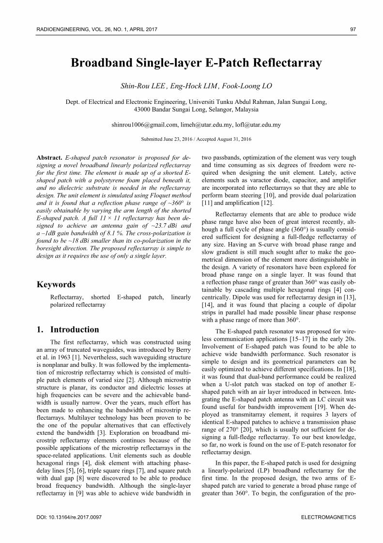
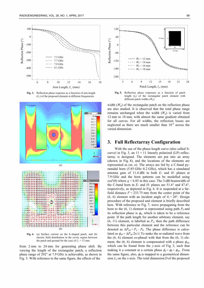
shown in Fig. 1(a) and (b). It consists of an E-shaped metal patch etched on the top surface of a piece of square poly-styrene foam (L L) with dielectric constant of r ~ 1 and thickness of h = 4 mm. The bottom surface of the foam is laminated with ground plane. The center arm of the E-shaped patch is shorted to the ground through via (diameter of d). With reference to Fig. 1(a), the shorting via is posi-tioned at a distance, s from the edge of the arm. To analyze its reflection properties, the proposed element with a cell size of 25 mm × 25 mm (L L) is simulated using the CST Design Studio. In simulation, as shown in Fig. 2, the pro-posed element is placed at one end of a square Floquet cell at a distance of 76 mm (in this case) from the wave port at another end, where a y-polarized plane wave with an inci-dent angle of θ = 20°, ϕ = 0° is launched. Since the refer-ence plane is always de-embedded to the top surface of the unit element, the distance between the port and element does not affect the reflection coefficient much. With refer-ence to Fig. 2, the top and the bottom surfaces of the Flo-quet cell are defined to be perfect-electric-conductor (PEC) walls while perfect-magnetic-conductor (PMC) walls for the two side walls. In order to take the mutual coupling mechanism between the elements into account, the unit element inside the Floquet cell is simulated as an infinite periodic array repeating itself. Figure 3 shows the reflec-tion phase (S11) curves at frequencies of 7.5 GHz (0.625), 7.7 GHz (0.642), 7.9 GHz (0.658) and 8.1 GHz (0.675). With reference to the same figure, by varying the two arms (L1) of the E-patch L1 from 5 mm to 18 mm, a reflection phase range of ≥ 360° can be easily obtained at the frequencies of 7.9 GHz and 8.1 GHz. In this case, the reflection phase slope at 7.9 GHz is selected for designing reflectarray. The reflection loss is not shown as it is less than 10-4 in the entire range. The arm widths (W1, W3) and gaps (G1 and G2) are made to be equal (3 mm). Other design parameters are W2 = 2 mm, L3 = 3 mm, L2 = 7 mm, s = 3 mm and d = 1 mm. The current distribu-
y
x4W
1G 2G
1W 3W
W2W2
L
L
3L
2L
1L1L
s
y
x4W
1G 2G
d
1W 3W
W2W2
L
L
3L
2L
1L1L
(a)
z
x
h
Ground
Foam
Shorting ViaE-patch
(b)
Fig. 1. (a) Top view. (b) Side view of the proposed E-patch unit element.
z
y
x
PMC
PMC
Foam
E
PEC
PEC
L
L Fig. 2. Simulation setting for the proposed unit element inside
a Floquet cell.
tions for the case of L1 = 12 mm are plotted on the patch in Fig. 4(a), and the corresponding electric fields in the cavity region between the patch and ground are depicted in Fig. 4(b). Typical current and field distributions for E-patch have been observed in both, comparable with those in [16]. To show the advantages of using the E-shaped patch, a rectangular patch element, with similar size and thickness, is designed and simulated at the same frequency. To begin, a unit element which consists of a rectangular patch on the top surface of a piece of square polystyrene foam (25 mm × 25 mm) with dielectric constant of r ~ 1 and thickness of 4 mm is designed. The bottom surface of the foam is laminated with ground plane. The rectangular patch has a width Wp of 16 mm and its length (lp) is varied
RADIOENGINEERING, VOL. 26, NO. 1, APRIL 2017 99
6 8 10 12 14 16 18
-500
-400
-300
-200
-100
0
100
Ref
lect
ion
Pha
se ()
Arm Length, L1 (mm)
7.5 GHz 7.7 GHz 7.9 GHz 8.1 GHz
Fig. 3. Reflection phase response as a function of arm length
(L1) of the proposed element at different frequencies
(a)
(b)
Fig. 4. (a) Surface current on the E-shaped patch, and (b) electric field distribution in the cavity region between the patch and ground for the case of L1 = 12 mm.
from 2 mm to 24 mm for generating phase shift. By varying the length of the rectangular patch, a reflection phase range of 292° at 7.9 GHz is achievable, as shown in Fig. 5. With reference to the same figure, the effects of the
3 6 9 12 15 18 21 24
-240
-180
-120
-60
0
60
120
lp
Wp
Wp = 12 mm Wp = 14 mm Wp = 16 mm Wp = 18 mm
Patch Length, l (mm)p
Ref
lect
ion
Pha
se ()
25 mm
25 mm
Fig. 5. Reflection phase responses as a function of patch length (lp) of the rectangular patch element with different patch widths (Wp).
width (Wp) of the rectangular patch on the reflection phase are also studied. It is observed that the total phase range remains unchanged when the width (Wp) is varied from 12 mm to 18 mm, with almost the same gradient obtained for all curves. For all widths, the reflection losses are neglected as there are much smaller than 10-4 across the varied dimension.
3. Full Reflectarray Configuration With the use of the phase-length curve (also called S-
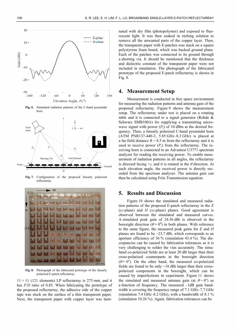
curve) in Fig. 3, an 11 × 11 linearly polarized (LP) reflec-tarray is designed. The elements are put into an array (shown in Fig. 8), and the locations of the elements are represented as (m, n). The arrays are fed by a C-band py-ramidal horn (5.85 GHz–8.2 GHz), which has a simulated antenna gain of 11.4 dBi in both E- and H- planes at 7.9 GHz and the horn patterns can be modelled using cosq(θ) where q = 6.85 in this case. The 3-dB beamwidth of the C-band horn in E- and H- planes are 51.6° and 47.4°, respectively, as depicted in Fig. 6. It is suspended at a far-field distance F = 233.75 mm from the center point of the (6, 6) element with an incident angle of θi = 20°. Design procedure of the proposed unit element is briefly described here. With reference to Fig. 7, wave propagating from the horn to the (6, 1) element is represented using path P0 and its reflection phase is 0, which is taken to be a reference point. If the path length for another arbitrary element, say (6, 11) element, is labelled as Pn, then the path difference between this particular element and the reference can be denoted as Pn0 = Pn – P0. The phase difference is calcu-lated as n0 = Pn0 2/. To make the re-radiated wave from the (6, 6) element co-phasal with that from the (6, 1) ele-ment, the (6, 6) element is compensated with a phase n0, which can be found from the y-axis of Fig. 3, such that making it a constant at a certain phase n = 0 + n0 . From the same figure, also, 0 is mapped to a geometrical dimen-sion L1 on the x-axis. The total dimension D of the proposed
100 S. R. LEE, E. H. LIM, F. L. LO, BROADBAND SINGLE-LAYER E-PATCH REFLECTARRAY
Fig. 6. Simulated radiation patterns of the C-band pyramidal
horn.
(6,6) (6,11)(6,1)
Pn
P0
y x
z
Shorting Via
F
Ground
Unit Element
D
Foam
i
Feed Horn
Fig. 7. Configuration of the proposed linearly polarized
reflectarray.
(1,1)
(1,6)
(11,11)
m
n
Fig. 8. Photograph of the fabricated prototype of the linearly
polarized E-patch reflectarray.
11 × 11 (121 elements) LP reflectarray is 275 mm, and it has F/D ratio of 0.85. When fabricating the prototype of the proposed reflectarray, the adhesive side of the copper tape was stuck on the surface of a thin transparent paper. Next, the transparent paper with copper layer was lami-
nated with dry film (photopolymer) and exposed to fluo-rescent light. It was then soaked in etching solution to remove all the unwanted parts of the copper layer. Then, the transparent paper with E-patches was stuck on a square polystyrene foam board, which was backed ground plane. Each of the patches was connected to its ground through a shorting via. It should be mentioned that the thickness and dielectric constant of the transparent paper were not included in simulation. The photograph of the fabricated prototype of the proposed E-patch reflectarray is shown in Fig. 8.
4. Measurement Setup Measurement is conducted in free space environment
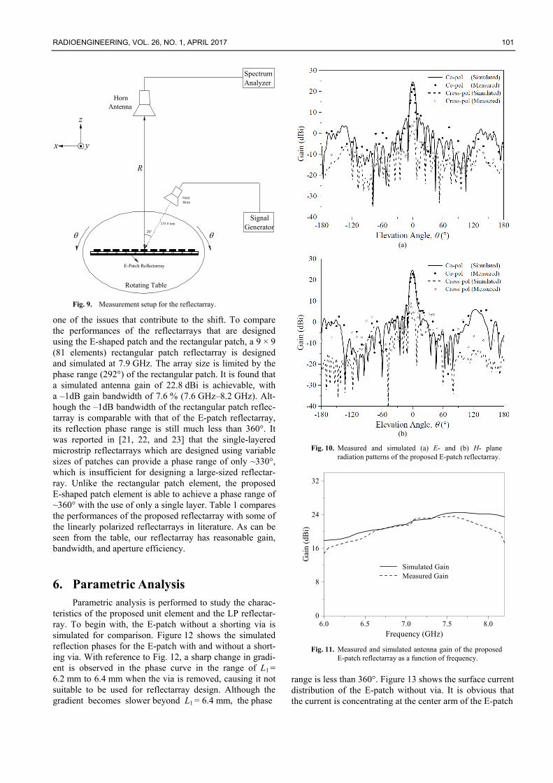
for measuring the radiation patterns and antenna gain of the proposed reflectarray. Figure 9 shows the measurement setup. The reflectarray under test is placed on a rotating table and it is connected to a signal generator (Rohde & Schwarz SMB100A) for supplying a transmitting micro-wave signal with power (Pt) of 10 dBm at the desired fre-quency. Then, a linearly polarized C-band pyramidal horn (ATM PNR137-440-2, 5.85 GHz–8.2 GHz) is placed at a far-field distance R = 8.5 m from the reflectarray and it is used to receive power (Pr) from the reflectarray. The re-ceiving horn is connected to an Advantest U3771 spectrum analyzer for reading the receiving power. To enable meas-urement of radiation patterns in all angles, the reflectarray is directed facing +z, and it is rotated in the direction. At each elevation angle, the received power is directly rec-orded from the spectrum analyzer. The antenna gain can then be calculated using Friis Transmission equation.
5. Results and Discussion Figure 10 shows the simulated and measured radia-
tion patterns of the proposed E-patch reflectarray in the E (yz-plane) and H (xz-plane) planes. Good agreement is observed between the simulated and measured curves. A simulated peak gain of 24.56 dBi is observed in the boresight direction ( = 00) in both planes. With reference to the same figure, the measured peak gains for E and H planes are found to be ~23.7 dBi, which corresponds to an aperture efficiency of 36 % (simulation 43.4 %). The dis-crepancies can be caused by fabrication tolerances as it is very challenging to solder the vias accurately. The simu-lated co-polarized fields are at least 20 dB larger than their cross-polarized counterparts in the boresight direction ( = 0o). On the other hand, the measured co-polarized fields are found to be only ~18 dBi larger than their cross-polarized components in the boresight, which can be caused by imperfections in experiment. Figure 11 shows the simulated and measured antenna gain (at = 0o) as a function of frequency. The measured –1dB gain band-width is covering the frequency range of 7.1 GHz–7.7 GHz (simulation 7.4 GHz–8.2 GHz), with a bandwidth of 8.1 % (simulation 10.26 %). Again, fabrication tolerances can be
RADIOENGINEERING, VOL. 26, NO. 1, APRIL 2017 101
Rotating Table
R
E-Patch Reflectarray
Horn Antenna
Spectrum Analyzer
233.8 mm
Feed Horn
SignalGenerator
yx
z
Fig. 9. Measurement setup for the reflectarray.
one of the issues that contribute to the shift. To compare the performances of the reflectarrays that are designed using the E-shaped patch and the rectangular patch, a 9 × 9 (81 elements) rectangular patch reflectarray is designed and simulated at 7.9 GHz. The array size is limited by the phase range (292°) of the rectangular patch. It is found that a simulated antenna gain of 22.8 dBi is achievable, with a –1dB gain bandwidth of 7.6 % (7.6 GHz–8.2 GHz). Alt-hough the –1dB bandwidth of the rectangular patch reflec-tarray is comparable with that of the E-patch reflectarray, its reflection phase range is still much less than 360°. It was reported in [21, 22, and 23] that the single-layered microstrip reflectarrays which are designed using variable sizes of patches can provide a phase range of only ~330°, which is insufficient for designing a large-sized reflectar-ray. Unlike the rectangular patch element, the proposed E-shaped patch element is able to achieve a phase range of ~360° with the use of only a single layer. Table 1 compares the performances of the proposed reflectarray with some of the linearly polarized reflectarrays in literature. As can be seen from the table, our reflectarray has reasonable gain, bandwidth, and aperture efficiency.
6. Parametric Analysis Parametric analysis is performed to study the charac-
teristics of the proposed unit element and the LP reflectar-ray. To begin with, the E-patch without a shorting via is simulated for comparison. Figure 12 shows the simulated reflection phases for the E-patch with and without a short-ing via. With reference to Fig. 12, a sharp change in gradi-ent is observed in the phase curve in the range of L1 = 6.2 mm to 6.4 mm when the via is removed, causing it not suitable to be used for reflectarray design. Although the gradient becomes slower beyond L1 = 6.4 mm, the phase
(a)
(b)
Fig. 10. Measured and simulated (a) E- and (b) H- plane radiation patterns of the proposed E-patch reflectarray.
6.0 6.5 7.0 7.5 8.00
8
16
24
32
Gai
n (d
Bi)
Frequency (GHz)
Simulated Gain Measured Gain
Fig. 11. Measured and simulated antenna gain of the proposed
E-patch reflectarray as a function of frequency.
range is less than 360°. Figure 13 shows the surface current distribution of the E-patch without via. It is obvious that the current is concentrating at the center arm of the E-patch
102 S. R. LEE, E. H. LIM, F. L. LO, BROADBAND SINGLE-LAYER E-PATCH REFLECTARRAY
Reference No.
No. of Reflectarray Element
Reflectarray Aperture Size
(mm2) Gain (dBi)
Gain Bandwidth Aperture Efficiency (%)
–1dB (%) –3dB (%)
24 27 × 27 = 729 405 × 405 28.5 8 - 34.12 (measured)
6 - 280 × 210 26.2 - 17 37 (measured) 25 29 × 29 = 841 246.5 × 246.5 34 8 - 41 (simulated) 5 21 × 31 = 651 190 × 270 24 - 18 35 (measured)
26 11 × 5 = 55 660 × 300 14.2 - 14.1 22.6 (simulated) This work 11 × 11 = 121 275 × 275 23.7 8.1 19.8 36(measured)
Tab. 1. Performances of the linearly polarized reflectarrays.
and there is no current flow to the two arms, resulting in less phase change when the lengths of the two arms are varied. On the other hand, the E-patch with via is able to achieve a phase range of ~360° with slow gradient.
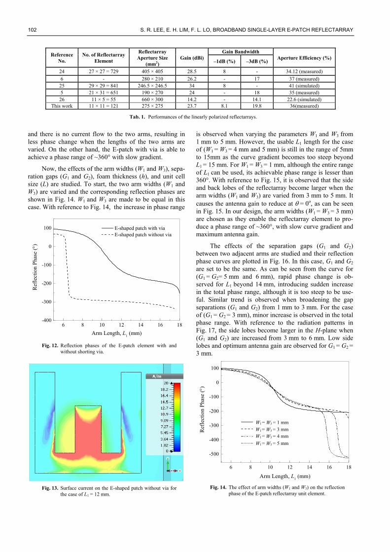
Now, the effects of the arm widths (W1 and W3), sepa-ration gaps (G1 and G2), foam thickness (h), and unit cell size (L) are studied. To start, the two arm widths (W1 and W3) are varied and the corresponding reflection phases are shown in Fig. 14. W1 and W3 are made to be equal in this case. With reference to Fig. 14, the increase in phase range
6 8 10 12 14 16 18-400
-300
-200
-100
0
100
Arm Length, L1 (mm)
Ref
lect
ion
Pha
se ()
E-shaped patch with via E-shaped patch without via
Fig. 12. Reflection phases of the E-patch element with and
without shorting via.
Fig. 13. Surface current on the E-shaped patch without via for
the case of L1 = 12 mm.
is observed when varying the parameters W1 and W3 from 1 mm to 5 mm. However, the usable L1 length for the case of (W1 = W3 = 4 mm and 5 mm) is still in the range of 5mm to 15mm as the curve gradient becomes too steep beyond L1 = 15 mm. For W1 = W3 = 1 mm, although the entire range of L1 can be used, its achievable phase range is lesser than 360°. With reference to Fig. 15, it is observed that the side and back lobes of the reflectarray become larger when the arm widths (W1 and W3) are varied from 3 mm to 5 mm. It causes the antenna gain to reduce at = 0o, as can be seen in Fig. 15. In our design, the arm widths (W1 = W3 = 3 mm) are chosen as they enable the reflectarray element to pro-duce a phase range of ~360°, with slow curve gradient and maximum antenna gain.
The effects of the separation gaps (G1 and G2) between two adjacent arms are studied and their reflection phase curves are plotted in Fig. 16. In this case, G1 and G2
are set to be the same. As can be seen from the curve for (G1 = G2= 5 mm and 6 mm), rapid phase change is ob-served for L1 beyond 14 mm, introducing sudden increase in the total phase range, although it is too steep to be use-ful. Similar trend is observed when broadening the gap separations (G1 and G2) from 1 mm to 3 mm. For the case of (G1 = G2 = 3 mm), minor increase is observed in the total phase range. With reference to the radiation patterns in Fig. 17, the side lobes become larger in the H-plane when (G1 and G2) are increased from 3 mm to 6 mm. Low side lobes and optimum antenna gain are observed for G1 = G2 = 3 mm.
6 8 10 12 14 16 18
-500
-400
-300
-200
-100
0
100
=
Arm Length, L1 (mm)
Ref
lect
ion
Pha
se ()
W1 = 1 mmW3
=W1 = 3 mmW3
=W1 = 4 mmW3
=W1 = 5 mmW3
Fig. 14. The effect of arm widths (W1 and W3) on the reflection
phase of the E-patch reflectarray unit element.

RADIOENGINEERING, VOL. 26, NO. 1, APRIL 2017 103
(a)
(b)
Fig. 15. Radiation patterns of the proposed E-patch reflectarray with different arm widths (W1 and W3). (a) E - and (b) H - planes.
6 8 10 12 14 16 18
-500
-400
-300
-200
-100
0
100
Ref
lect
ion
Pha
se ()
Arm Length, L1 (mm)
=G1 = 1 mmG2
=G1 = 3 mmG2
=G1 = 5 mmG2
=G1 = 6 mmG2
Fig. 16. The effect of gap separations (G1 and G2) on the
reflection phase of the E-patch reflectarray unit element.
(a)
(b)
Fig. 17. Radiation patterns of the proposed E-patch reflectarray with different gap separations (G1 and G2) between two adjacent arms. (a) E - and (b) H - planes.
Subsequently, the thickness of the foam (h) is varied and its reflection phase response is shown in Fig. 18. It is observed that the reflection phase range increases when h is increased from 2 mm to 7 mm. For the case of h = 7 mm, the gradient of the phase curve becomes very steep when the arm length (L1) goes beyond 16 mm, and this portion cannot be used for designing reflectarrays limited by our fabrication precision. As a result, the achievable phase range ~260° is not sufficient for designing a full-fledge reflectarray. On the other hand, for the case of h = 2 mm, the unit element is able to produce a phase range of 327°, which is slightly less than one full cycle (360°).
Next, the effects of the unit cell size (L) on the reflec-tion characteristics are studied. The reflection phase curves for L = 0.606and 0.711are almost overlapping, as can be seen from Fig. 19. The cell size is translated into separation distance between two adjacent elements when the unit element is employed for designing a full-fledge

104 S. R. LEE, E. H. LIM, F. L. LO, BROADBAND SINGLE-LAYER E-PATCH REFLECTARRAY
reflectarray. The radiation patterns for separation distances of 0.606and 0.711are depicted in Fig. 20. An-tenna gain in the boresight direction is found to be larger with lower backlobe level when the separation distance is increased. This can further improve the front-to-back ratio, which is much desirable. In our design, however, the sepa-ration distance is selected to be L = as the side lobes are lower for this case.
With the use of L = and the reflectarray dimension of D = 11L = 275 mm, the radiation patterns of the reflectarray for different F/D ratios are illustrated in Fig. 21. It is obvious that the front-to-back ratio decreases when the F/D ratio is increased from 0.85 to 0.95.his can be caused by spill-over losses when the focal distance is increased. However, the ratio can’t be made too small as it has to satisfy the far-field criterion. In our case, it is found that the reflectarray design with F/D = 0.85 and focal distance of 233.75 mm has given the best radiation perfor-mance.
6 8 10 12 14 16 18
-500
-400
-300
-200
-100
0
100
Arm Length, L1 (mm)
h = 2 mm
h = 4 mm
h = 7 mm
Ref
lect
ion
Pha
se ()
Fig. 18. The effect of foam thickness (h) on the reflection
phase of the E-patch reflectarray unit element.
6 8 10 12 14 16 18
-500
-400
-300
-200
-100
0
100
L = 0.606
L = 0.658
L = 0.711
Ref
lect
ion
Pha
se ()
Arm Length, L1 (mm)
Fig. 19. The effect of the unit cell size (L) on the reflection phase response of the proposed unit element.
(a)
(b)
Fig. 20. Radiation patterns of the proposed E-patch reflectarray with different unit cell sizes. (a) E - and (b) H - planes.
(a)
Fig. 21. (a) Radiation patterns of the proposed E-patch reflectarray with different F/D ratios: E - planes.

RADIOENGINEERING, VOL. 26, NO. 1, APRIL 2017 105
(b)
Fig. 21. (b) Radiation patterns of the proposed E-patch reflectarray with different F/D ratios: H - planes.
6 8 10 12 14 16 18
-500
-400
-300
-200
-100
0
100
= 10
= 20
= 25
Ref
lect
ion
Pha
se ()
Arm Length, L1 (mm)
Fig. 22. The effect of feeding angle (θ) on the reflection phase of the E-patch unit element.
(a)
Fig. 23. (a) Radiation patterns of the proposed E-patch reflectarray for different feeding angles (θ): E - planes.
(b)
Fig. 23. (b) Radiation patterns of the proposed E-patch reflectarray for different feeding angles (θ): H - planes.
Finally, the feeding angle (θ) is studied. It can be observed from the unit cell simulation that the reflection phase does not vary much when the proposed unit element is fed with an incident angle of 10°, 20° and 25°, as shown in Fig. 22. But it has much effect on the radiation patterns. With reference to Fig. 23, it is noticed that the side and back lobes of the reflectarray become larger when the feeding angle is increased from 10° to 25°. To reduce the effect of feeder blockage, the feeding angle of 20° is selected for our design.
7. Conclusion A single-layer E-patch reflectarray has been proposed
for broadband applications. The unit element has extremely small reflection loss and a phase range of ~360o. With the use of this element, a full reflectarray has been designed and fabricated. Measurement shows an antenna gain of ~23.7 dBi and a –1 dB gain bandwidth of 8.1 %. Paramet-ric analysis has been conducted and it was found that the radiation performance of the full reflectarray can be further optimized by manipulating some of the design parameters such as foam thickness, arm length, F/D ratio, and incident angle. The proposed reflectarray is very simple as it does not require the use of any dielectric substrate. It can provide sufficient phase range using one layer. Also, the antenna is lightweight and it can be manufactured with minimum cost.
Acknowledgments
The work described in this paper was supported by the Science Fund (Project No.: 06-02-11-SF0154) provided by the Ministry of Science, Technology and Innovation, Malaysia. Part of the project was also sponsored by the UTAR Research Fund 2013 (Project No.: 6200/LA5).
106 S. R. LEE, E. H. LIM, F. L. LO, BROADBAND SINGLE-LAYER E-PATCH REFLECTARRAY
References
[1] BERRY, D., MALECH, R., KENNEDY, W. The reflectarray antenna. IEEE Transactions on Antennas and Propagation, 1963, vol. 11, no. 6, p. 645–651. DOI: 10.1109/TAP.1963.1138112
[2] POZAR, D. M., TARGONSKI, S. D., SYRIGOS, H. D. Design of millimeter wave microstrip reflectarrays. IEEE Transactions on Antennas and Propagation, 1997, vol. 45, no. 2, p. 287–296. DOI: 10.1109/8.560348
[3] ENCINAR, J. A. Design of two-layer printed reflectarrays using patches of variable size. IEEE Transactions on Antennas and Propagation, 2001, vol. 49, no. 10, p. 1403–1410. DOI: 10.1109/8.954929
[4] ARSHAD, M. K., TAHIR, F. A., RASHID, A. Design of a single layer reflectarray unit cells based on hexagonal ring for wideband operation. In Proceedings of IEEE International Symposium on Antennas and Propag. (APSURSI). Memphis (Tennessee), 2014, p. 815–816. DOI: 10.1109/APS.2014.6904735
[5] HASANI, H., KAMYAB, M., MIRKAMALI, A. Broadband re-flectarray antenna incorporating disk elements with attached phase-delay lines. IEEE Antennas and Wireless Propagation Letters, 2010, vol. 9, p. 156–158. DOI: 10.1109/LAWP.2010.2044473
[6] MALFAJANI, R. S., ATLASBAF, Z. Design and implementation of a broadband single-layer reflectarray antenna with large-range linear phase elements. IEEE Antennas and Wireless Propagation Letters, 2012, vol. 11, p. 1442–1445. DOI: 10.1109/LAWP.2012.2228147
[7] VOSOOGH, A., KEYGHOBAD, K., KHALEGHI, A., el al. A high-efficiency ku-band reflectarray antenna using single-layer multiresonance elements. IEEE Antennas and Wireless Propagation Letters, 2014, vol. 13, p. 891–894. DOI: 10.1109/LAWP.2014.2321035
[8] ISMAIL, M. Y., SULAIMAN, N. H. Enhanced bandwidth reflectarray antenna using variable dual gap. In Proceedings of the 2nd International Conference on Instrumentation, Communications, Information Technology, and Biomedical Engineering (ICICI-BME). Bandung (Indonesia), 2011, p. 92–96. DOI: 10.1109/ICICI-BME.2011.6108601
[9] HAMZAVI-ZARGHANI, Z., ATLASBAF, Z. A new broadband single-layer dual-band reflectarray antenna in X- and Ku-bands. IEEE Antennas and Wireless Propagation Letters, 2015, vol. 14, p. 602–605. DOI: 10.1109/LAWP.2014.2374351
[10] ZAINUD-DEEN, S. H., GABER, S. M., AWADALLA, K. H. Beam steering reflectarray using varactor diodes. In Proceedings of Japan-Egypt Conference on Electronics, Communications and Computers (JEC-ECC). Alexandria (Egypt), 2012, p. 178–181. DOI: 10.1109/JEC-ECC.2012.6186979
[11] MAKDISSY, T., GILLARD, R., FOURN, E., et al. Phase-shifting cell for dual linearly polarized reflectarrays with reconfigurable potentialities. IEEE Antennas and Wireless Propagation Letters, 2014, vol. 13, p. 11–14. DOI: 10.1109/LAWP.2013.2294873
[12] KISHOR, K. K., HUM, S. V. An amplifying reconfigurable reflectarray antenna. IEEE Transactions on Antennas and Propagation, 2012, vol. 60, no. 1, p. 197–205. DOI: 10.1109/TAP.2011.2167939
[13] FLORENCIO, R., BOIX, R. R., ENCINAR, J. A. Design of a reflectarray antenna at 300 GHz based on cells with three coplanar dipoles. In Proceedings of IEEE International Symposium on Antennas and Propagation (APSURSI). Orlando (Florida), 2013, p. 1350–1351. DOI: 10.1109/APS.2013.6711335
[14] YOON, J. H., YOON, Y. J., LEE, W. S., et al. Broadband microstrip reflectarray with five parallel dipole elements. IEEE Antennas and Wireless Propagation Letters, 2015, vol. 14, p. 1109–1112. DOI: 10.1109/LAWP.2015.2394810
[15] YANG, F., ZHANG, X. X., YE, X., et al. Wide-band E-shaped
patch antennas for wireless communications. IEEE Transaction on Antennas and Propagation, 2001, vol. 49, no. 7, p. 1094–1100. DOI: 10.1109/8.933489
[16] ANG, B. K., CHUNG, B. K. A wideband E-shaped microstrip patch antenna for 5-6GHz wireless communications. Progress In Electromagnetics Research, 2007, vol. 75, p. 397–407. DOI: 10.2528/PIER07061909
[17] RAZZAQI, A. A., MUSTAQIM, M., KHAWAJA, B. A. Wideband E-shaped antenna design for WLAN applications. In Proceedings of IEEE 9th International Conference on Emerging Technologies (ICET). Islamabad (Pakistan), 2013, p. 1-6. DOI: 10.1109/ICET.2013.6743550
[18] LIU, S., WU, W., FANG, D. G. Single-feed dual-layer dual-band E-shaped and U-slot patch antenna for wireless communication application. IEEE Antennas and Wireless Propagation Letters, 2016, vol. 15, p. 468–471. DOI: 10.1109/LAWP.2015.2453329
[19] CHEN, Y., YANG, S., NIE, Z. Bandwidth enhancement method for low profile E-shaped microstrip patch antennas. IEEE Transactions on Antennas and Propagation, 2010, vol. 58, no. 7, p. 2442–2447. DOI: 10.1109/TAP.2010.2048850
[20] LUO, J., YANG, F., XU, S. E-shaped element design for linearly polarized transmitarray antennas. In Proceedings of IEEE International Symposium on Antennas and Propagation (APSURSI). Kaohsiung (Taiwan), 2014, p. 269–270. DOI: 10.1109/ISANP.2014.7026634
[21] POZAR, D. M., METZLER, T. A. Analysis of a reflectarray an-tenna using microstrip patches of variable size. Electronics Letters, 1993, vol. 29, no. 8, p. 657–658. DOI: 10.1049/el:19930440
[22] TARGONSKI, S. D., POZAR, D. M. Analysis and design of a microstrip reflectarray using patches of variable size. In Proceedings of International Symposium on Antennas and Propagation. Seattle (Washington, USA), 1994, p. 1820–1823. DOI: 10.1109/APS.1994.408184
[23] TARGONSKI, S. D., POZAR, D. M., SYRIGOS, H. D. Analysis and design of millimeter wave microstrip reflectarrays. In Proceedings of International Symposium on Antennas and Propagation. Newport Beach (California, USA), 1995, p. 578 to 581. DOI: 10.1109/APS.1995.530085
[24] GUO, L., TAN, P. K., CHIO, T. H. Design of an X-band reflectarray using double circular ring elements. In Proceedings of the 7th European Conference on Antennas and Propagation (EuCAP). Gothenburg (Sweden), 2013, p. 2947–2950. ISBN: 978-1-4673-2187-7
[25] ABD-ELHADY, M., HONG, W. Ka-band linear polarized air vias reflectarray. In Proceedings of IEEE Middle East Conference on Antennas and Propagation (MECAP). Cairo (Egypt), 2010, 3 p. DOI: 10.1109/MECAP.2010.5724213
[26] LI, L., CHEN, Q., YUAN, Q., et al. Novel broadband planar reflectarray with parasitic dipoles for wireless communication applications. IEEE Antennas and Wireless Propagation Letters, 2009, vol. 8, p. 881–885. DOI: 10.1109/LAWP.2009.2028298
About the Authors... Shin-Rou LEE (B.S. (Hons) from Universiti Tunku Abdul Rahman 2014, currently taking a full time Master Degree (Research) there) focuses her main research interests in reflectarray and transmitarray antennas.
Eng-Hock LIM and Fook-Loong LO (both Ph.D., City University of Hong Kong) focus their research interests on dielectric resonator antennas, reflectarray, transmitarray, RFID; baseband communications, signal processing.