broadcast - 4tubes.com4tubes.com/literature/english/.../radio-broadcast/... · broadcast...
TRANSCRIPT
RADIOBROADCAST
How toUse the Screen-Grid Tube
ADirectory of Manufactured Receivers
Hints onOperatincftour CooleyRayfotoReceive
ThePhonographJoins tKeRadioReceiver
A Push-Pull Amplifier and B SupplyInside the Complete Receiver
i
35 Qmts 'X^pr JAN -*92Vitv. jVewUork^ -J

RADIO! TUBES
SINCE 1915 STANDARD fOR ALL SETS
CUNNINGHAM'
;cx;|oi-A
giftsthat bring happiness at
Christmas time and
throughout the yearRadio sets and radio equipment make
immensely popular Christmas gifts.
To assure the utmost in Yule-tide Radio
enchantment, see that Cunningham RadioTubes are on duty in every socket. Everyowner of a radio will be delighted to re-
ceive a set of new tubes.
Buy them in combination of five or more.
Your dealer will tell you the correct typesof Cunningham Radio Tubes for which
any radio set is designed.
Don't use old tubes with new ones.
Use new tubes throughout.
E. T. CUNNINGHAM, Inc.
New York Chicago San Francisco
I

RADIO BROADCAST ADVERTISER 191
Improve
Reception!
ELECTRADCertifiedLead-ins
Eliminate insulation trou-
bles at the entrance pointof your aerial and have bet-
ter reception by using: this
superior constructed Lead-in.
Bends any shape to fit aroundthe corners and under locked doorsor windows. Triple-ply insulation
full 10 inches, covered with water-
proof webbing. One piece copperstrip heavily tinned to preventcorrosion.
Protect yourself by looking for
the Electrad name. Price 40ceach. At your dealers.
Write for DescriptiveCirculars
Dept. 61B, 175VarkkSt., New York, N.Y.
ELECTRADfROST-RADIOOFFERS RADIO BROADCASTREADERS TWO VALUABLENEW BOOKLETS FREE!
Write for ThemWE OFFER readers of Radio^* Broadcast two valuable newFrost-Radio publications free onrequest : "What Set Shall I
Build?" the answer to a questionwhich puzzles many set builders,and the new Frost booklet "ForBetter Reception," a complete and.
helpful manual of Frost Parts.
Every set builder should have bmiiof these booklets. They will befound chock-full of useful infor-mation that is right up to theminute.
FROST-RADIOWhat they Contain"What S.-t Shiill I Build?"telK much about the newestand most popular circuits"For Better Reception" tells
you proper size rheostat formill 1
1 i nil" sets, has wiringdlnRfHins for high resistanceunit, and contains valuablefacts about Frost-Radio Parts.
fMSTRAMO
FROST-RADIO
Mail Coupon NOWTo secure these t wo I >ok -
lets FREE nil out and mailcoupon below, printing yourname and address carefully.These books will amaze youwith their completeness.Write for them to-dayNOW.
HERBERT H. FROST,Inc. Elkhart, Indiana
Chicago New Vork
HERBERT H. FROST, Inc.160 North La Salle Street, ChicagoI'ltMx- send me free your two booklets, as advertised InRadio Broadcast for January.
Name
Street Address
City State . .
Powerft
Quality
\ PUSH-PULL amplifier in that last stage provides the speaker with ample** power to sustain a high volume level without tube overloading, transmit-
ting the full effects of large swings in intensity common in orchestra music.
This balanced type of amplifier draws no alternating current from the plate
supply, a fact of great importance if socket power is used, as the impedanceof the power unit does not affect the amplifier. This results in improved re-
production of sustained notes, particularly of low frequency.
Other advantages of the push-pull system are, a reduction in hum when al-
ternating current is used for filament supply and for equal power outputs, areduction in the plate voltage required.
The amplifier is supplied completely wired.
Type 441 amplifierFor use with UX 226, CX 326, UX 171, CX 371, UX 210, or CX310 tubes.
Input inductance 30 henries.
Input turns ratio i :2.25.
Output impedance ratio 12:1.
(whole primary to secondary)
Price completely wired $20.00.
Licensed by the Radio Corporation of America for radio amateur, experi-mental and broadcast reception only and under the terms of the R. C. A.license the unit may be sold only with tubes.
GENERALRADIOLABORATORY EQUIPMENTPARTS and ACCESSORIES
If we can be of help to you in supplying technical
information, we welcome your correspondence. Writefor our Series A of amplification booklets describingvarious amplifiers, circuits and units.
GENERAL RADIO CO. Cambridge, Mass.

RADIO BROADCASTJANUARY, 1928
WILLIS KINGSLEY WING, Editor
KEITH HENNEV EDGAR H. FELIX
Director of the Laboratory Contributing Editor
Vol. XII, No. 3
Cover Design *. From a. Design by Harvey Hopkins Dunn
Frontispiece- ' - In the Laboratory of a Tube Manufacturer 194
Radio Enlists the Helium Atom - Volney G. Mathison 195
The March of Radio An Editorial Interpretation 198Can the Serious Problem of Radio Patents Be What Readers Say About Broadcasting
Settled?
The Prospects of a Patent Pool
The Commission Announces a New Policy
Conditions
Broadcasting Bands ChangedBroadcasting Notes
The Commission Suggests Synchronization News of the Patent Field
Schemes Among the Manufacturers
Push-Pull Amplification Why? - Howard E. Rhodes 202
The Phonograph Joins the Radio Set 206
The Screened Grid Tube Keith Henney 208
What Set Shall I Buy? - Edgar H. Felix 211
"Our Readers Suggest 213
Why I Installed a Cooley Picture Receiver - Edgar H. Felix 215
Suppressing Radio Interference - - - A. T. Lawton 217
Are Programs Going in the Wrong Direction? -
John Wallace 219The Listeners' Point of View
A Vacuum'Tube Voltmeter - The Laboratory Staff 221
Radio Folk You Should Know 225(i.) Ralph H. Langley Drawing by Franklyn F. Stratford
Some Fine Receivers and Their Chassis - 226
"Strays" from the Laboratory - 228How Reliable are Short Waves? High-Powered BunkMathematics of the Audio Transformer New Apparatus
Concomitants of Good Quality - .- 230
How the "Synchrophase" Seven Was Developed John F. Rider 232
As the Broadcaster Sees It Carl Dreher 235
"Radio Broadcast's" Laboratory Information Sheets 238No. 153. Standard' and Constant-Frequency No. 157. Table for Wavelength-Freauency
Stations ConversionNo. 154. The na-A and 171-* Type Tubes No. 158. The Three-Tube Roberts ReflexNo. 155. Wave Traps No. 159. Diagram of Three-tube RobertsNo. 156. Wavelength-Frequency Conversion Reflex
No, 160. Fading
Manufacturers Booklets Available - - 244
"Radio Broadcast's" Directory of Manufactured Receivers 246
A Key to Recent Radio Articles E. G. Shall<hauser 255
What Kit Shall I Buy? ..>'*, 257
AMO^G OTHER THINGS. . .
ITIS a sad duty to record the death of the Chairman of the
Federal Radio Commission, Admiral W. H. G. Bullard,
which occurred in Washington on Thanksgiving Day. Admiral
Bullard, who served in the United States Navy for thirty-six
years, for a very long time was close to the center of radio in
almost all of its branches. His loss will be keenly felt, not only
by those who knew him as a likable and able individual but
especially by the Radio Commission itself. When the RadioCommission went to work on March 15, two of its membershad a background of technical radio experience. These two menwere Admiral Bullard and Colonel Dillon. Death has removedboth. The Commission at this writing now consists of Acting-Chairman E. O. Sykes, O. H. Caldwell, Sam Pickard, andH. A. Lafount. Not one of these members has a technical radio
background which would enable them to better struggle withthe complicated problems which confront them.
THE reports of international conferences, on whatever
subject, usually make rather dull reading for the general
public and the Washington Radio Conference has beer. 11O
exception to this rule. The proceedings may not be exciting, but
the results are certainly important. There has been no revision
of international agreement since the London conference of 1912,and radio progress has been so rapid since then that the articles
of that Convention were hopelessly inadequate to meet presentneeds. There have been many rocks and shoals in the way of
the present conference, which, at this writing, has just woundup its work, but through good management and a praiseworthydesire for general accord, the delegates have succeeded in
drawing up a Convention which well meets the needs of radio
today. Not the least important decision reached at Washingtonwas that dealing with the international assignment of channels
in the frequency spectrum. In that respect, we are glad to note,the future needs of short-wave communication, broadcasting,
commercial, and amateur work were provided for. The ama-
teurs had a hard fight, but room has been saved for them a
result of which the broad-minded directors of the AmericanRadio Relay League may well be proud.
THE issue of RADIO BROADCAST before you contains some
extremely interesting articles. The story by HowardRhodes on the problems of push-pull amplification is distinctly
helpful and should cast much light on a form of amplificationwhich is again being revived after several years of comparativedisuse. . . . Those who are anxious to know what the newscreened-grid tube will do will find Keith Henney 's article veryvaluable indeed. As soon as possible, RADIO BROADCAST will
give its readers data on receiving circuits which can be used
with the tube; the latter has just been released for general sale.
THOSEof our readers who would like to have their names
forwarded to the manufacturers of the special apparatus
necessary to construct a Rayfoto receiver may send letters to
the undersigned, and printed matter containing detailed in-
formation will be sent them. . . . The next RADIO BROADCASTwill contain an article describing a new super-heterodyne,
entirely operated from a. c., which has much to recommend it,
both from the design and appearance point of view. Therewill also be many other articles of interest.
WILLIS KINGSLEY WING.
Doubleday, Page & Co.
MAGAZINESCOUNTRY LIFEWORLD'S WORKGARDEN & HOME BUILDERRADIO BROADCASTSHORT STORIESEDUCATIONAL REVIEWLE PETIT JOURNALEL Eco
'
FRONTIER STORIESWEST WEEKLYTHE AMERICAN SKETCH
Doubleday, Page Gr Co.
BOOK SHOPS.
(Hooks of all Publishers)
5
LORD & TAYLOR BOOK SHOPPENNSYLVANIA TERMINAL (2 Shops t
GRAND CENTRAL TERMINAL38 WALL ST. and 526 LEXINGTON AVE.
, 848 MADISON AVE. and 166 WEST }2NDST.ST. Louis: 223 N. 8TH ST. and 4914 MARYLAND AVE.KANSAS CITY: 920 GRAND AVE. and 206 W. 47TM ST.CLEVELAND: I In, MI Co.SPRINGFIELD, MASS.: MEEKINS. PACKARD& WHEAT
Doubleday, Page Sr Co.
OFFICES
GARDEN CITY, N. Y.
NEW YORK: 285 MADISON AVENUE
BOSTON: PARK SQUARE BUILDING
CHICAGO: PEOPLES GAS BUILDING
SANTA BARBARA, CAL.
LONDON: WM. HEINEMANN LTD.
TORONTO: OXFORD UNIVERSITY PRESS
OOUBLEDAT, PAGE & COMPANY, Garden &ty,Copyright, 1927, in the United States, Newfoundland, Great Britain, Canada, and other countries by Doubleday, Page
TERMS: $4.00 a year; single copies 3? cents.
192
Doublfday, Page & Co.
OFFICERS
F. N. DOUBLEDAY. President
NELSON DOUBLEDAY, / ue-President
S. A. EVERITT, Vice-President
RUSSELL DOUBLEDAY, Secretary
JOHN J. HESSIAN, Treasurer
LILLIAN A. COMSTOCK, Assl. Secretary
L. J. McNAUGHTON, Asst. Treasurer
Company. All rights reserved.

RADIO BROADCAST ADVERTISER 193
OUJuJlmpli
THORDARSON 171 TYPEPOWER AMPLIFIER
Built around the Thordarson Power Compact R-171, this
Power amplifier supplies "A," "B," and "C" current for onet/X-171 power tube and B-voltage for the receiver. EmploysRaytheon B. H. rectifier.
THORDARSON 210 TYPEPOWER AMPLIFIER
This amplifier, mounted on a special metal chassis, uses theThordarson Power Compact R-21Q. Provides "A," "B," and"C" current for one UX.-21} power tube and "B" voltage forthe receiver. Employs one 216-B o/ 281 rect:fier.
A Home AssembledThordarson Power AmplifierWill Make Your Receiver
A Real Musical Instrument
^IMPROVEMENTS in the newer model receiv
JJ ing sets are all centered around the audio ampli'fier. There is no reason, however, why you cannot
bring your present receiver up to 1928 standards of
tone quality by building your own ThordarsonPower Amplifier.
With a screw driver, a pair of pliers and a soldering
iron you can build any Thordarson Power Ampli'fier in an evening's time in your own home. Com'
plete, simple pictorial diagrams are furnished with
every power transformer.
i i
The fact that Thordarson power trans'
formers are used by such leading manu'
facturers as Victor, Brunswick, Federal,
Philco and Willard insures you of mvquestionable quality and performance.
Give your radio set a chance to reproduce real
music. Build a Thordarson Power Amplifier.
Write today for complete constructional booklets
sent free on request.
THORDARSON 210 PUSH-PULLPOWER AMPLIFIER
This heavy duty power amplifier operates two 210 power tubes
in push-pull and has an ample reserve ofpower for "B" supplyfor the heaviest drain receivers. Built with Thordarson PowerTransformer T-2098, and Double Choke Unit T-2099.
THORDARSON ELECTRIC MANUFACTURING CO."Transformer Specialists Since 1895
WORLDS OLDESTAND LARGEST EXCLUSIVE TRANSFORMER MAKERSand Kingsbury Streets Chicago. 1'II. USA.
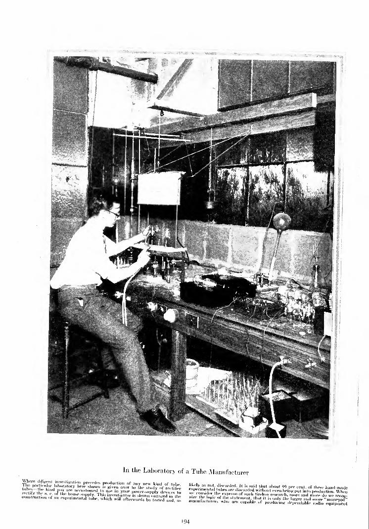
In the Laboratory of a Tube Manufacturer
Where diligent investigation precedes production of any new kind of tnhelikely as not, discarded. It is said that about 99 per cent of these hand-mud.,expcnmental tubes are discarded without even bei ,K put into prudSot ton Whinwe cons,der the expense of such tireless research, more and ,,,"",!, we' recogm*. the og,c ,,f ,he statement that it is only ,he larger and more "moneyed*'manufacturers who are capable of producing dependable radio equipment
194

STUDYING GASES IN THE LABORATORYLooking into the depths of ionized helium atoms with a spectroscope. Charles Grover Smith,who is shown in this picture, spends considerable of his time studying gases, especially helium
RADIO ENLISTS THE HELIUM ATOMBy VOLNEY G. MATHISON
IT'S
all so useless, that's why I'm quitting,"
complained the young college graduate to
the chief of the laboratory in which he had
lately gotten a job. "What can ever come out of
measuring the ohmic resistances of a cubic mil-
limeter of about a million different substances
under a couple of hundred different tempera-tures? That's the job you've given me nothingbut an endless measuring of ohms. -If this is
what you call scientific research
"It is," interrupted the electro-chemist."
It's the backbone of it prolonged patience at
tedious work."
"Seefns tedious enough. But I could stand that
if I could see some results ahead. I can't see
any."
"Well, there may be no directly importantoutcome of what you're doing. You are simply
adding to the stock of scientific knowledge in a
prosy way, working on a huge book of tempera-ture-resistance tables. You can't tell in advancewhat it may lead to. Take, for example, the
helium-gas rectifier tube used in radio B-supplydevices. It was never invented, it just grew out
of a lot of laborious work like this. Americanfactories are turning out about 20,000 of these
tubes a day at present and the patent profit is
close to a dollar and a half apiece. There's a
return to pure research at the rate of somethinglike $30,000 a day. That soon pays for a lot of
slow laboratory grinding, doesn't it?"
"Yes," reiterated the young graduate, "butthat tube wasn't developed by any such work as
I'm doing here measuring the resistances of
rust, rocks, roots, cocoanut shell, and the end
years away. It's all so discouraging!"As a matter of fact, the helium-gas tube for
B-devices was the result of a great amount of
purely scientific work of the tedious and rather
unfocussed sort that this discouraged youngchemist was assigned to, though, perhaps, the
experiments involved were a good deal moretechnical. A few years ago we began studyingthe actions of electrons in gases. At that time
nobody knew much about electrons maybe wedon't yet and the experiments were entirely
general in kind. The aim was to find out some-
thing, not to invent something. One young fellow
had the job of finding out definitely whether or
not electrons emitted from a cathode into a tube
of gas passed through the gas without collidingwith its atom centers.
An atom of any kind of substance, as nearly
every one now is aware, consists of a group of
protons and electrons surrounded by planetaryelectrons. The space in between seems to contain
nothing but electric tension, though now late in
1927 we are about to believe that this tension
consists of a flurry of particles called etherons
that are so small they make an electron look
like a balloon in comparison with an apple, andmove almost twice as fast as light. Matter.even
"95
solid steel, is nearly all emptiness, and it is the
crudeness of our undeveloped physical senses
that makes us think otherwise.
So this young man set about trailing a lot of
wandering electrons through a wilderness of gasesto find out what they did in there. He had a
photographing outfit that would show the pathsof the electrons. Many gases and pressures had
to be tried. In one series of experiments each
photograph showed the flight of 200,000 elec-
trons, and that young man took 100,000 photo-
graphs separately, one after the other, before he
got one collision of an electron with the middle
of an atom of the gas under test. He kept on, and
got a total of eight collisions in 400,000 photo-
graphs. Even when it is possible to use a fast
automatic machine to take such photographs,
they all have to be individually and laboriouslyexamined.
The photographer found out something else.
He found out that when an electron hit an atomof gas square in the middle, it blew the atom to
pieces, producing a shower of unattached elec-
trons, and unsmashable groups of electrons and
protons that were named alpha particles. Alphaparticles were identified with a spectroscope as
being the same as a mysterious gas which had
been seen by astronomers pouring over the sun,
and which they had named helium a "sun"word.
The alpha particles or helium atoms can be

196 RADIO BROADCAST JANUARY, 1928
quite easily robbed temporarily of one planetary
electron, but they cannot be further broken upexcept with the most extreme difficulty. Helium
gas was therefore recognized as a valuable elec-
trical conducting medium that would tend to
act at all times with unchanging properties and
that would refuse to eat, corrode, or combine in
any way with the metal tips of the electrodes bywhich electricity would be fed into the gas. Noparticular electrical use for this gas had yet
been thought of, though it was proposed that
metal-ended glass cartridges of helium might be
valuable as ultra-stable resistors capable of
withstanding enormous currents and pressures.
In photographing the flights of electrons
through helium gas, it was observed that, whenan electron struck an atom of helium, the elec-
tron ran off with one of the planetary electrons
of the helium atom, carrying it to the anode.
A sketch of this performance would be almost
inconceivably out of proportionsince there would have to be rep-
resented the trillions times trillions
of atoms in the tube, while elec-
trodes about the size of the state
of Georgia would be necessary to
preserve the proper scale if the
atoms were one half inch across.
If the helium nucleus were drawn
the size of a pea, the planetaryelectrons would properly be placeda quarter of a mile away. Such is
the ghastly emptiness of matter
of even the "solid" walls of a
glass tumbler from which we drink
billions of electrons and protons in
the peculiarly ordered state we call
water; and of the stout iron bars
upon which the jail-bird leans his
head. But solidity, although physi-
cally an illusion, is nevertheless real
because it is a manifestation of
a powerful electrical condition.
To return now to the story of
the doings in the helium tube un-
der electrical pressure, we learn
that the unfortunate gas atom that
has lost an electron is said to be
"ionized." This is all that ioniza-
tion means, i. e., a breaking awayof electrons from gas atoms. It,
the ionized atom, is over-positively
charged and flies with terrific force
toward the negative or cathode
element, which it strikes violently
and from which it extracts an
electron from the inflowing stream
in the wire leading to the cathode
the entrance element from the outside supply.The gas atom, now once more in a normal state,
rebounds from the cathode and flies about
jubilantly until it is again robbed of an electron,
when it instantly goes through the perform-ance just described all over again.One remarkable thing about this action which
is not yet understood is the fact that the bom-bardment of the cathode by ionized gas particles
causes a liberal release of free electrons of extra
electrons beside those taken to balance the
ionized atoms. In other words, by hammering a
negative electrode with positively charged gas
particles, we get a discharge of electrons. Per-
haps the "yanking" out of the electron needed
by the atom for itself is so violent that several
extra electrons are hustled out along with it.
Some of these extra electrons in their flight to
the positive or exit element collide with other gas
molecules, and the action, the pounding of gas
particles on the cathode and the emission of elec-
trons, is continuous as long as electrical pressure
is applied to the device. A current consequently
flows through the tube. In this manner elec-
tricity gets through a cold-electrode rectifier
tube.
HOW A TUBE RECTIFIES
HpHE foregoing does not explain how current*
gets through the tube in only one direction.
It would seem that, when the tube is put in an
a. c. circuit, each element would become alter-
nately an anode and a cathode, an exit and
an entrance, and that the flow would be equallyback and forth through the gas in the tube.
But since the current flow depends upon hittingan electrode with gas particles, it becomes ap-
parent that, by making one electrode big and the
other one little, you can facilitate the hitting in
one direction and minimize it in the other. Whenthe larger electrode is negative, it will get thor-
oughly hammered with gas particles and will
release many electrons; consequently, a large
BEHIND THE SCENES IN THE LABORATORY
Preparing a globe of pure helium for research experiments. This kind ofwork never stops, and in every progressive tnbe concern, the laboratoryis always ahead of the factory is always working on
"something better."
current will flow through the device. On the other
hand, when the smaller electrode goes negativeunder the reversing a. c. current, it will not be
battered so much by the flying gas particles as
the other electrode was and therefore will not
emit many electrons. A small current will, how-
ever, flow. The big electrode is a better emitter
because it has more surface for the gas particlesto "rip" electrons out of. When the big electrode
is positive and the small electrode is negative,the ionized gas atoms do fly toward the small
electrode but most of them miss it because it
is comparatively hard to hit. Some particlesstrike the small element while it is negative andrelease electrons which fly across to the large
electrode. This produces a "back-current"
through the tube. All helium-gas rectifier tubes
have this "back-current." The amount of it
determines the efficiency of the rectifier and it
usually is but a small percentage of the current
in the other direction.
The "back-current" is reduced by makingthe anode small and hard, while the other large
electrode is treated with radioactive earths to
encourage it to release electrons. Besides the
difference in size of the bombarding areas of the
two elements, the electric field produced by the
smaller electrode is less attractive to the ionized
gas particles than that of the larger one, with the
result that it is hit less violently.
Both of the elements are made principally of
nickel, which has been purified in a hydrogenfurnace to remove all impurities.The description so far has dealt with a tube in
which there are only two elements. The usual
helium-gas rectifier tube has three elements
a hat-shaped or tubular cathode and two anodes.
This is simply two rectifier tubes in one, using a
common cathode, and enables both halves of the
a. c. wave to be used. The action here is exactlythe same as that already described, except that
the emission of electrons is alternately from the
cathode to first one anode and then to the other
to each one as it becomes positive
in turn. And the cathode is almost
continuously under bombardment,because it is always negative with
respect to one anode or the other.
At the same time that the flight of
electrons takes place from the
cathode to the positive anode, a
"back-current" emission travels
from the temporarily negativeanode toward the cathode. Someelectrons also fly between the two
anodes, causing "leak" current.
These "leak" and "back-cur-
rents," while not wanted, cannot
be entirely eliminated, and as longas they are small, cause no serious
trouble. In the factories, each tube
is tested on a machine that meas-ures the "back-current," and if
excessive, the tube is discarded.
Too much "back-current" througha tube will cause a B-device to
hum.It is worth pointing out that the
popular 'conception of the move-ment of electricity through a B-
device rectifier and filter systemis erroneous. The general idea is
that a "positive current" getsacross the rectifier tube into the
filter where it is tanked arid chokedinto smoothness. But it should be
remembered that current is purelyelectronic flow it consists only of
moving electrons in a conductor
and these electrons flow only from
negative to positive. It is very con-
fusing to the novice and entirely unnecessary to
say that the current flows one way and the elec-
trons the other. There is no such current flowing
against the movement of the electrons. It simplydoesn't exist. In the early days of electrical
science, long before any kind of a radio vacuum-tube had even been thought of, experimentersmisunderstood some of the actions of electricity,
and the positive-to-negative idea of current flow
was one of the consequences of their lack of
knowledge. In the business of science, there is
no sensible reason for compromising with mis-
takes or twisting them around to meet new facts,
as is being attempted all the time in religion;
they should be simply left out of the story.The electrons flowing in a B-device circuit
enter the negative wires, pass direct to the fila-
ments of the vacuum-tubes in the radio receiver,
are emitted from the hot filaments to the plates,
pass from the plates through the various circuits
to the positive lead of the B device, thence
through the chokes to the cathode element of the
rectifier tube, and from this point they are

JANUARY, 1928 RADIO ENLISTS THE HELIUM ATOM 197
sprayed alternately to the anode elements as
these become positive in turn under the inductive
action of the a. c. current in the primary power-
supply windings. The filter chokes and tanks pre-
vent a voltage and current fluctuation in the
line during the intervals between the spraying
or emission surges through the rectifier tube.
So deeply ingrown is the current-flow con-
ception that in a recent issue of a well-known
radio magazine there was a cut of a helium-gas
tube with the hat-shaped cathode marked
"anode" and the two anodes marked "cath-
odes." The accompanying text used the same
terminology, which was wrong even in the light of
the old theory. It should be clear that the posi-
tive side of a B-device filter is of negative
potential compared to the ends of the secondary
winding of the power transformer to which the
rectifier-tube anodes are connected. The large
cathode of a helium rectifier is equivalent to the
incandescent filament of the filament type tube.
WHY A TUBE DETERIORATES
CINCE the helium-gas rectifier tube contains^ no heated filament emitter to burn out or
become lifeless through deterioration, manyusersof thedevice feel that it ought to last almost
forever for years and years at any rate, and
wonder why it sometimes has a short life.
As a matter of fact, the developers of the tube
themselves thought at first that it would have a
life of 10,000 hours or more of continuous use,
but soon found that such was not the case. The
principal thing that brings the life of a helium-
gas rectifier tube to an end is the fact that the
helium gas in the bulb disappears. Helium gas is
inert, it will not combine with anything, so far
as we know at present; it is genuinely strange,
therefore, that it should disappear from a her-
metically-sealed bulb. It seems that the ionized
gas particles pound the cathode with such force
that some of them are driven deep into the metal
and stay there become occluded or imprisoned.After a certain length of time so many gas
atoms are bound in the metal that the tube be-
comes very hard, the vacuum rises, and the
bombardment of the cathode becomes meager,
owing to the reduced number of molecules of
gas to do the battering. The current output of
the tube then falls off to such a point that it
must be discarded.
The life of many a good helium-gas tube has
been quickly brought to an end through the
breaking down of condensers in filter circuits.
Cheap inferior condensers in both home-madeand factory-built power devices usually go to
pieces after a few weeks or months of use, with
the result that the rectifier tube is placed in a
dead short-circuit. The heavy current flow
quickly burns off the tips of the anodes in the
tube. The helium gas itself cannot be injured by
any current. Helium gas will carry currents so
great that they will instantly explode copperconductors of the same cross-sectional area;
but under such currents the gas particles quicklydrive themselves deep into the negative elec-
trodes and are as good as lost.
Some of the cheaper helium-gas tubes now on
the market may be short-lived through the
presence of impurities in the helium, which would
destroy the electrodes. Extremely pure helium
must be used. This gas is purified by passing it
through copper tubes filled with cocoanut char-
coal and maintained at the temperature of liquid
air more than 250 below zero, Fahrenheit; then
to a steel reservoir; then to a second battery of
tubes of charcoal surrounded with liquid air
to remove oxygen or nitrogen which might come
away from the walls of the reservoir. The helium
is admitted until the charcoal is partly loaded
with it; next it is pumped off with vacuum
pumps and the impurities remain in the char-
coal, which is itself purified and used over again.
It is interesting to consider that absolute
purification of anything, liquid, gaseous, or solid,
is almost impossible. Imagine for a moment that
you could mark molecules in some such waythat you could identify them when you saw them
again. Assume that you took a glass of water
with the molecules of water all thus marked and
stirred it into the waters of the oceans of this
earth, that you waited a couple of million yearsfor thorough mixture, and that you then walked
up to the nearest hydrant in your vicinity and
casually drew a glass of water, you would find
about 2000 of your marked molecules in it! Of
course, we may be a few molecules out on this
estimate, but that is roughly the correct mathe-
matical number, because there are 2000 times
as many molecules in a glass of water than there
are glasses of water on the earth.
Again, molecules of air, if admitted into a
highly-evacuated 25-watt electric light bulb
through a hole so small that they had to flow in
single file, would take about 100,000,000 yearsto fill it to atmospheric pressure. A little re-
flection will show that "purity," like everything
else, is probably only a relative condition.
"Some of 'em is more pure, and some of 'em is
less pure, but none of 'em is all pure," said the
sour cynic, and while he wasn't speaking of gases,
and was not a scientist for that matter, he was
uttering profound truth.
THE TIN "HAT"
VA/HAT is the queer tin "hat" for in the*"
modern gaseous rectifier tube? Nobodyoutside of the research laboratories 'seems to
know. Even some of the "bootleggers" makingthese tubes don't know.
In the early experimental forms of the helium-
gas tube, great trouble was met with owing to
the disruption of the cathode element under the
hammering of the ionized gas atoms. The earlier
tubes had disk shaped cathodes, and the gasatoms pulled out electrons with such violence
that tiny pieces of solid metal were often rippedloose from the electrode. These metal bits were
thrown against the glass walls of the tube,
blackening it, and resulting in the speedydestruction of the cathode.
For this reason the peculiar tin-hat form of
cathode was evolved because, with this arrange-
ment, the bombardment of the cathode and emis-
sion of electrons is entirely internal. The action
all takes place inside of the electrode. If a bit of
metal is torn from the cathode at any point, it is
hurled across the inner chamber and thrown
back onto the element somewhere else. There is
no loss of metal because the cathode is continu-
ally built up as fast as it is torn down.
It seems that, if we, as human beings, could be
temporarily reduced to the size of, say, an atom,
together with a corresponding ability to see
small objects, and were then placed upon the
cathode of an operating helium-gas rectifier tube,
we would have an impression of standing amongranges of heaving mountains of metal in a state
of furious convulsion and uproar, bombarded
with enormous meteors of helium and full of
volcanic upheavals and earthquake-like shocks,
while electrons would arise like clouds of steam
on all sides, or spurt out like fiery sparks.
.
A VIEW OF THE LABORATORY IN WHICH THE HELIUM-GAS RECTIFIER TUBE WAS PERFECTED

I HI- MANFWS AND INimPKHATIQN OF r.UUUI-'NT UAmQ KVHNI I V~
Can The Serious Problem of Radio Patents Be Settled?
THErecent adjudication of several
important patents, such as those of
Hazeltine and Alexanderson, has
forced upon the radio industry the longdeferred day of reckoning with inventive
genius. Conscientious and established man-ufacturers have proceeded promptly to ob-
tain licenses under Radio Corporation
patents which make available to them the
work of some of the world's greatest labora-
tories. By assuming an annual royalty
guarantee of one hundred thousand dollars
a year, charged at the rate of 75 per cent,
of the cost of radio receivers, they becomelicensed under R. C. A., A. T. & T., West-ern Electric, General Electric, Westing-house and Wireless Specialty patents.
Having assumed this substantial burden,the licensees considered their patent diffi-
culties disposed of. But some quickly found
that licenses under Hazeltine and Latour
patents are also necessary to freedom from
patent difficulty and, probably quite re-
luctantly, signed the Hazeltine licenses with
the additional burden of a 25 per cent,
royalty and an annual guarantee of thirtythousand dollars a year. This duty per-
formed, the manufacturer dismissed patenttrouble and consecrated himself to the
problem of selling newer and better radios.
And then came the independent inventor
to disturb his peace of mind. Old patentswere dug up, demanding recognition. Newpatents, just issued, added to the swarm.
Some of these inventions are as worthy of
recognition as those covered by the Radio
Corporation license. Others may be worth-
less and which will not withstand the test
of adjudication.The weary manufacturer's answer to
those demanding additional royalties is be-
coming less and less courteous. He is now
paying all that the traffic will bear. Unless
some remedy is offered, his answer to patentholders soon will be: "A plague upon yourpatents!"
The Prospects of a Patent Pool
SOMEmanufacturers have united in de-
fensive groups to protect themselves
against the swarm of inventions whichnow confronts them. They foresee the neces-
sity for so great an increase in the price of
radio receivers by reason of patent royaltiesthat the public will no longer be able to
afford them. Faced with the alternatives of
excessive royalties or occasional injusticeto the legitimate inventor, the manufac-turers have, quite naturally, tended to the
latter course.
No doubt, some of the inventors, whoseclaims for royalties are being disregardedor opposed, will eventually win adjudica-tions, and triple damages, if they are suf-
ficiently patient and prosperous to afford
the protracted legal battle which must pre-cede such a result. It is quite possible that
combined resistance to the inventor may,in some cases, prove costly, because it is
not reasonable to assume that Radio Cor-
poration, Latour and Hazeltine patentsare the only ones which will be favorably
adjudicated.Combined resistance, however, is the only
course open to the manufacturer because
there are too many unadjudicated patents
demanding attention. It would be suicidal
to agree to a license under all of them; the
cost of radio sets to the consumer would
double and sales resistance would fourfold.
Most of the executives in the radio field
wish to concentrate their attention on the
design, manufacture and merchandising of
radio equipment, but patent problems now
require an alarming proportion of their
time. Naturally, the leaders of the radio
industry are nervous. At every trade con-
vention and meeting, we hear talk of anall-inclusive patent pool.
Unfortunately, no patent pool can be
successfully organized unless it has the
unanimous support of all radio manufac-turers and patent holders. To relieve the
patent situation economically and pain-
lessly, there must be a single, powerful,radio trade organization. Nevertheless, the
N. E. M. A. and the R. M. A. still to
all outward appearances indulge in short-
sighted rivalry. An unofficial canvass of
ninety per cent, of the membership of oneof these organizations reveals that all but
two were in favor of consolidation. To makea consolidation possible, one or two leaders
in the R. M. A. must for a moment forgetthat their organization has the largestnumber of members and the youngestblood, and one or two members of the
N. E. M. A. must forget some remarksmade several years ago over matters longsince settled. And both groups must cease
suspecting each other.
CHANGES IN THE FEDERAL RADIO COMMISSIONHcmy Miller
Henry A. Bellows, Sam Pickard.and Carl H. Butman. Commissioner Bellows was appointed from the Minneapolis district where he had long ably managedwcco. His resignation, effective November ist, left a vacancy which was filled by the President in appointing Sam Pickard who has been Secretary to
the Commission since its appointment. Carl Butman is the new Secretary succeeding Mr. Pickard and has many years of experience in Washington as
news correspondent, specializing in radio, to aid him in his new post. Mr. Butman has for some time been Washington correspondent for RADIO BROADCAST
,98

JANUARY, 1928 ACTIVITIES OF THE RADIO COMMISSION 199
The industry is headed for one of the
most dangerous shoals in its career. Doubt-
less, it will weather it successfully. But
how long the shoal will impede its progress
depends upon how successful it is in placing
the ship in the hands of one pilot, instead
of two squabbling deck hands, to guide it
past the patent whirlpool. It will require
leadership of the highest order to establish
a patent pool.
In the future, there will be a new and
greater industry, much greater than we
imagine to-day. The radio receiver is but
a nucleus of a home entertainment device
which will rival the automobile in useful-
ness and entertainment value and, in the
end, its gross sales figures will be as large
as those of the envied motor car industry.
The radio receiver, the phonograph, the
motion picture machine and the television
receiver will, some day, be available in a
single, compact, home-entertainment de-
vice. The public will pay as much for a
versatile means of home entertainment as
for an automobile to take them away from
home. The more the leaders of the radio
industry concentrate upon the develop-ment of radio and the establishment of its
true market, the sooner they will have a
five-billion-dollar industry. At present, the
most vital aid in that objective would be
turning over radio's patent problems to a
patent pool. The alternatives are continued
squabbles, continued patent fights, and a
radio market still limited to about ten percent, of the American public.
The Commission Announces a
New Policy
THEFederal Radio Commission re-
cently announced a long list of al-
location changes which have been
made with the purpose of improving the
channels of a few of the leading stations of
the country. The Commission it is ru-
mored, will hereafter work on the theorythat there are a few leading, national sta-
tions, which are the favorites of listeners
all over the country and therefore deserve
clear channels, entirely free of interference
to the limit of their range. This is the basis
upon which several years ago Secretary of
Commerce Hoover worked out the plan of
Class A and Class B broadcasting stations
and urged on the commission in these
columns for more than a year.
Following this plan, WHAZ, which shared
time with WGY, was shifted to share time
with WMAK, giving powerful and popularWGY a full channel. WJAR, Providence, wasshifted from 620 kc. to 800, eliminating
widespread heterodyningwith WEAF, ten kc.
off, experienced throughout southern NewEngland. WEEI, Boston, was shifted from
670 to 650 kc., avoiding a heterodyne im-
posed upon it by a Chicago station. WTRL,a little station in Tilton, New Hampshire,formerly occupying a channel adjacent to
wjz, was shifted downward in order to
eliminate a whistle which it thrust on wjz'scarrier in large parts of New England.WDWM of Asbury Park, New Jersey, was
shifted so as to eliminate conflict with
WSAI'S carrier. WNAC of Boston and WEANof Providence, Columbia chain members,were made channel-sharing stations, prob-
ably in the interests of better management,and moved quite far into the unpopular
higher frequency region. WCAU, a Philadel-
phia advertising station and now a mem-ber of the Columbia network and WKRC of
the same chain were demoted from the
lower frequency region. WOR now has wosof Jefferson City, Missouri, as a channel
neighbor instead of wsui, Iowa City. Webelieve the Missouri station is more power-
fully received in Newark and will therefore
accentuate slightly the whistle which
already mars WOR'S programs.Another station to benefit by the Com-
mission's reallocation is KSD, St. Louis,
which is given full time. KSD is one of the
pioneers of broadcasting and is deservingof the consideration which the Commissionhas shown.
The conclusion that N. B. C. stations
have fared better than Columbia chain
stations is inescapable, but it must not be
forgotten that the former do include mostof the pioneer stations of the country which
have served faithfully and well for years,while most of the latter have not yet wontheir spurs in public estimation. Clearingthe channels of the N. B. C.'s leading sta-
tions cannot be criticized, but it might havebeen better policy to have concentrated
less on Columbia stations when the de-
moting process was begun.
The Commission Suggests
Synchronization Schemes
IN
A speech before the American In-
stitute of Electrical Engineers, Com-missioner O. H. Caldwell made some
remarks about the problems of maintaininga broadcasting station on its assigned fre-
quency. He mentioned three methods of
accomplishing this purpose, one well knownand widely used, one successfully used ex-
perimentally but economically prohibitive,and a third which is a rather unfortunate
suggestion. It is the Commissioner's idea
that, if complete frequency stability could
be secured and the heterodyne interference
between stations now assigned to the samechannels eliminated, more stations could
safely occupy the same channel. While this
is true, it must be realized that the audio-
frequency components of two stations onthe same channel also affect each other.
When the distant station does not come in
with sufficient volume to cause cross talk,
it often causes irregular distortion.
Cyrstal control, the first method sug-
gested for synchronizing carriers, is not
sufficiently stable to solve the problem.
Temperature and humidity changes affect
the frequency of the crystal and, conse-
quently, it does not give the absolute regu-lation necessary for successful occupancyof the same channel by two broadcastingstations whose carrier ranges overlap.The second method suggested, the use of
a wire circuit for the transmission of a con-
A WIRELESS STATION IN 1904A 35-kw. spark transmitter was erected by the old De Forest Company for the Navy near San Juan,Porto Rico. The illustration shows the receiving installation with Mr. Irodell, operator for the DeForest Company using the receiving equipment which consisted of a "pancake" tuner and an electro-
lytic detector. It was not until 1906 that a carborundum detector was substituted for the electro-
lytic one. The call signal of this station, which may be recalled by old-timers, was SA.

200 RADIO BROADCAST JANUARY, 192!
trolling frequency, which has been success-
fully employed by WBZ and WBZA at
Springfield and Boston, has the disadvan-
tage of being prohibitively expensive. For
example, if WOR attempted to eliminate the
heterodyne whistle caused by wos at
Jefferson City by this method, it would
probably cost some fifty thousand dollars
a year. To stabilize the whole broadcastingstructure would require perhaps five yearsto erect sufficient telephone channels for
the purpose and an expenditure of perhaps
twenty million dollars a year in mainte-
nance.
The third suggestion made by the Com-missioner was prompted by a suggestionfrom WDRC of New Haven, Connecticut,a 5OO-watt station. A heterodyne whistle,
originating from the carrier of WAIU, a
jooowatt station in Columbus, Ohio,about 500 miles distant, had been suffi-
ciently annoy ing to require drastic measures.To solve this problem, a receiving station
was installed five miles from New Haven,connected by wire lines with WDRC'S trans-
mitter. By tuning this receiving set care-
fully so that the heterodyne whistle is
eliminated, WDRC'S carrier is adjusted to
coincide with that of WAIU. So long as the
operator is vigilant and skillful, there is no
heterodyne whistle.
But, if the whole broadcasting structure
depended for frequency stability uponmanual control, it would become a sorrymess. One need but recall the days of the
regenerative receiver, with its heterodyningcarrier of but a tiny fraction of a watt.
Then imagine manually controlled broad-
cast transmitters with hundreds and thou-
sands of watts power, trying to establish
zero beat with each other. The incident
again emphasizes the fact that the Com-mission is sadly in need of technical assist-
ance which will help the members to grap-
ple more wisely with their problems. Anycompetent engineer could have pointed out
the dangers of this ingenuous panacea.
What Readers Say About Broad-
casting Conditions
THEfollowing are quotations from readers
of these editorials. George Madtes, Radio
Editor of the Youngstown Vindicator,
writes: "1 have no doubt that the re-allocation
of frequencies has materially helped stations in
New York and Chicago, but it has not attained
the Commission's apparent goal an arrange-ment which would permit listeners everywhere to
enjoy the stations nearest them. We are within
fifty miles of stations in Cleveland, Pittsburghand Akron and depend upon them for local
service. Our four main stations in these cities,
WTAM, KDKA, WCAE, and WADC are often hetero-
dyned and WADC and WCAE are almost invariablyuseless at night."W. W. Muir of Lockport, New York writes:
"One cannot help but notice the difference be-
tween the stations which are operating in the
few wave bands on which there is only one station
and those operating on the frequencies on whichthere are more than one station. The stations
which are operating on exclusive channels are
usually free from distortion, the signal being
strong and clear. The stations which are operat-
ing on wavelengths on which there are more than
one station show a decided tendency to be mushyand weak, and have a wide variation in signal
strength from moment to moment One cannot
help speculating what is apt to take place in the
future. We know that the American public have
had lots of things put over on them without
complaint. It is hard to believe that they will be
willing to stand for the huge joke that it is
possible to successfully operate more than one
powerful broadcasting station on a single fre-
quency without serious interference."
Another correspondent writes from Wyomingto the effect that KOA, Denver, is the principal
reliance for summer and winter reception of the
entire state. The Federal Radio Commission has
ordered that station to cut its power in half after
seven in the evening. Continuing, he writes: "Prac-
tically every strong station near the east coast is
located on the same frequency as some powerfulstation on the west coast. While probably theydo not interfere in their home territory, the
heterodyne of the two completely ruins receptionin the Rocky Mountain region. Before the recent
changes, we could usually depend on woe,
HOW VISITORS SEE THE ATWATER KENT FACTORY
Davenport, and wcco, St. Paul, for WEAF pro
grams, but have been unable to locate either fo
a long time."
Another correspondent .vrites from Ohio tha
he is located "forty-eight miles air line fron
WTAM, 102 miles from wWj and 95 miles fron
WAIU . . . WTAM fades so badlv at night that i
is worse than useless, wwj is 'crowded to death
on both sides. There is not one station in thi
group, or any other station, that can be receive!
here without heterodyning. Yet the Chairman o
the Federal Radio Commission reports the dis
trict very much improved. It is all bunk. Somstations must be eliminated."
INTERNATIONAL CONFERENCE CHANGESBROADCASTING BANDS
'"THE International Radio Telegraph Con* ference at this writing is still in session ii
Washington. Very few of the articles of the nev
international agreement have yet been adoptedSome opposition has appeared to the Americai
proposal that no more spark stations shall b
licensed and that steps be taken to eliminat
gradually those in existence with a view to thei
complete disappearance in 1935. The eliminatioi
of spark transmitters is proposed largely in thi
interests of the broadcast listener.
In the matter of frequency allocations, th<
amateurs, as usual, have defended their positioi
with great heat. The Japanese delegation, ii
particular, was far from cordial in its attitudi
toward amateurs. The British, French and German governments sought lower frequencychannels for broadcasting in the 1000-, 1300-
1500- and i8oo-meter regions, in addition to thi
usual bands in general use. It was finally decide(
to consolidate these requests for a longer wavi
broadcasting band of setting aside 1500 to ij5<
meters (200 to 194 kc.)'for the purpose, provid
ing about two channels with ten-kc. separationAt this writing, this band is not yet officially
approved, but is likely to stand.
The Committee on frequency allocation, whili
favorably inclined toward the recommendation:
of the American delegation for the broadcastinj
band, does not, at this writing, plan to devoti
the entire 500- to i 5Oo-kc. region to broadcastinj
purposes. In the plan announced, it proposes t<
utilize the lower 200 kc. (i.e. from 130010 ijookcor 230 to 200 meters) for both broadcasting anc
ship stations. This does not mean that the 27;
American broadcasting stations, now occupyinjthat part of the band, will have to get off, but i
is likely that ship interference will develop a
this end of the broadcasting channels. This movion the part of the International TeiegraplConference will undoubtedly accentuate stil
further the need for curtailing the number o
broadcasting stations on the air in the Unitec
States.
BROADCASTING NOTES
THENational Broadcasting Company and th<
British Broadcasting Company will cooperate in several short-wave international pro
grams. In 1924, wjz participated in the first at
tempt at international broadcasting by relayA dance music program from the Savoy Hotewas radiated from England and intercepted a:
Houlton, Maine, and from there sent by wire t<
wjz, in New York. The fading experienced or
the i6oo-meter wavelength, (187 kc.) upon whicl
the program was relayed, was sufficient to dis
courage further attempts along these lines a
that time. With the development of short-wavt
transmitters, however, more reliable results ma)be expected, f ? f IN A statement of its policj
on international broadcasting, the British Broad-
casting Company lays considerable stress uporthe failures of previous attempts along thes(

JANUARY, 1928 BRIEF NEWS ABOUT IMPORTANT RADIO MATTERS 201
[lines. It describes an experimental relay of pro-
i grams for Sidney as barely recognizable; a paral-
lel attempt to relay Melbourne a few days later
as a complete silence. It regrets that so much
emphasis has been laid upon the possibilities of
international broadcasting and points out that
considerable development work is necessary be-
fore we can hope for regular and reliable inter-
national broadcasting. I I t E. T. SOMERSETwrites us from Sussex, England, that he enjoys
WGY, wjz, WLW, WEAF and KDKA on their regular
broadcasting channels, but American programscome in with much greater regularity on the high
frequencies. 2XAZ, WGY'S short-wave twin is the
star performer, with KDKA on twenty-six meters
and ZXAF following. He has also heard with
great clarity, 2XAH, WRNY and WLW on its short
wave, and ANH, Radio Malabar, Bendosng, Java,
on 17.4 meters and last, but not least, 2ME,
Sidney, Australia. It gave him a particular thrill,
he writes, to hear the clock striking four A. M. in
Sidney, when it was still seven p. M., British
summer time, of the previous night. Mr. Somer-
set advises American fans to listen for 5 OB,
Daventry, England, on a frequency of 610 kc.
with 30 kw. output, and Langenberg, Germany,with a 25 kw. output on a frequency of 640 kc.
Iff SAM PICKARD, who first gained fame in
radio circles as director of the Department of
Agriculture Radio Service, has been made Fed-
eral Radio Commissioner to succeed Henry A.
Bellows, recently resigned to resume the manage-ment of wcco. The Commission loses Mr. Bel-
lows because the gentlemen of the Congressfailed to confirm his appointment. He was a use-
ful and hardworking Commissioner. Mr. Pickard
is qualified to serve on the Commission because
of his familiarity with its problems as its former
secretary. Carl H. Butman now becomes Secre-
tary of the Commission. He is well known to the
newspaper fraternity and may be helpful to the
Commission, not only as an efficient secretary,
but 'n advising it how to handle its relations with
the press and the public. I I f"
I HAVE come to
the conclusion that it is not a practical or even a
theoretical advantage to a broadcaster to sponsora program through any small station. The com-
panies that are marketing national products can
use radio advertising to excellent advantage but
for local companies to broadcast through a small
local station is not good advertising, in my opin-ion. Their efforts are so mediocre in comparisonwith the programs sponsored by the big com-
panies and transmitted through the high powerof a well equipped, well operated station, that a
bad impression is made and no benefit is derived."
That is the statement, not of a newspaper pub-lisher, but of Mr. Robert A. Fox, of Ashland,
Ohio, who owned and operated station WLPC.
Realizing that the small station serves little use-
ful purpose, WLPC requested the Federal RadioCommission to cancel its license and its ownernow states that he wishes "about two hundredmore stations, now operating, would do the
same." f I f THE DEPARTMENT OF AGRICULTUREFarm Radio Service is being broadcast byeighty-nine radio stations in thirty-four states.
Each of these stations will broadcast one or moreof the eleven regular farm and household radio
services prepared and released by the U. S. De-
partment of Agriculture. Such services as these
help to sell radio to the farmer.
NEWS OF THE PATENT FIELD
I EE DEFOREST won a victory over Edwin*-
Armstrong in the United States Circuit Courtof Appeals at Philadelphia, which decided that
he is the inventor of the regenerative or feed-backcircuit and the oscillating audion. Since the rightto use both DeForest and Armstrong patents is
included in the R. C. A. license, the decision does
not affect the R. C. A's licensees particularly.
Certain companies, however, operated under
licenses granted by Armstrong before his patentwas acquired by the Westinghouse Company,appear, through this decision, to be liable for
royalties under the DeForest patent. There is
a possibility that this case may now reach the
Supreme Court, although that body has the
power to refuse to consider the matter. ? f f THEMACKAY interests announce that the DeForest
victory places them on an equal footing with the
Radio Corporation of America in the field of
wireless communication. They will undertake
immediate steps to establish short-wave wireless
systems across the Pacific Ocean and throughoutthe United States, f f J PATENT No. i ,639,042,
recently issued to Wilford MacFadden of
Philadelphia and assigned to the Atwater Kent
Manufacturing Company, describes the use of
a potentiometer for the stabilization of radio-
frequency amplifiers. This system was used ex-
tensively before the neutrodyne systemof stabili-
zation was developed, f f ? THE DUBILIER
Condenser Company has notified a number of
manufacturers of the scope of patents 1,635,1 17,
1,606,212, and 1,455,141, describing plate-
current supply devices and power amplifiers.
Included among prospective defendants under
these patents are various Radio Corporationlicensees. One of these patents describes a power
system comprising rectifiers, filter and choke
circuits, using a. c. on the filaments; another, a
two-stage power amplifier with
alternating current on the fila-
ments and a C battery used to
obtain grid bias; plate potential is
obtained from a thermionic recti-
fier.
AMONG THE MANUFACTURERS
TH E Sonora Phonograph Com-
pany, manufacturers and dis-
tributors of phonographs and radio
sets, the Bidhamson Company, a
patent holding corporation, organ-ized by John Hays Hammond, Jr.,
Lewis Kausman and others, and the
Premier Laboratories, headed byMiller Reese Hutchinson, have
recently merged to form a corpora-tion devoted to the manufacture
of acoustic devices, f f f ARTHURD. LORD, receiver in equity of the
DeForest Radio Company, has
filed a complaint with the Federal
Trade Commission on Clause IXof the R. C. A. license contract.
This clause specifically forbidsR. C. A. licensees to equip and
sell licensed radio sets without
equipping them with R. C. A. or
Cunningham tubes to make them
initially operative. In his com-
plaint, Mr. Lord claims that the
consumer is penalized because he
is forced to take a tube which
otherwise might not be his choice.
The clause is obviously aimed at
independent tube manufacturers.
He expfesses the belief that this is
an attempt at monopoly and re-
straint of trade, a direct violation
of the Federal Trade Commission
Act, the Clayton Act and the
Sherman Anti Trust Law. if "f I
IN FULL page newspaper advertise-
ments in the principal newspapersof the country, Mr. A. AtwaterKent announced a price reduction
of twenty per cent, in his receiv-
ing sets. This reduction, says the
announcement, is made possible by tremendous
increase in production facilities. Particularly in
the lower price classes, we may expect an era of
intensive price competition with consequent ad-
vantages to theconsumer. I t f POWELCROSLEY,
JR., has announced that his Bandbox model will
probably not be changed for several years. This
is the first time that a manufacturer has ven-
tured such a prediction, fit THE STEWARTWARNER Speedometer Corporation, which has
long defied the R. C. A. in patent matters, is the
most recent addition to the ranks of those com-mitted to a 75 per cent, royalty.
A STATEMENT by Dr. J. H. Dellinger,
calls attention to a general current mis-
understanding regarding short-wave beam com-munication. The international short-wave beamlinks confine the radiated energy to a thirty-
degree arc which is indeed not concentration in a
single narrow path. It represents merely. Doctor
Dellinger points out, an economic advantageand not a secrecy system.
Science has been unable to affect a concentra-
tion of radiated wave energy, either light, sound,
or heat, in a perfect single beam by the aid of
any form of reflector, and there seems little
ground for hope that we shall soon achieve it
with radio telegraphy or telephony. The conceptthat we may reduce beam transmission to a
concentration comparable to that obtainable bywire communication is now untenable.
THE NEW COAST GUARD SHORT-WAVETRANSMITTER
B. J. Fadden, chief radioman aboard the U. S. C. G. Modoc in
ice patrol duty is shown standing beside the 35.5-meter(85oo-kc.) transmitter. The transmitter on this wave is usedfor direct communication between the Modoc while in theNorth Atlantic ice fields and headquarters in Washington

RADIO BROADCAST Photograph
MAKING FINAL ADJUSTMENTS ON THE PUSH-PULL AMPLIFIER DESCRIBED IN THIS ARTICLEMeasurements of the grid bias voltage are being made. Note the electro-dynamic Magnavox loud speaker in the background. A circular baffle-
board has been attached to it in the laboratory
PUSH-PULL AMPLIFICATION WHY?By HOWARD E. RHODES
THEessential prerequisites for faithful
reproduction from a radio set are, first,
a properly designed receiver capable of
giving reasonably distortionless amplification
and, secondly, a good loud speaker fed with
power from a source able to supply the necessary
energy without overloading. Much of the dis-
tortion in receivers is due to tube overloading,
which usually occurs to the greatest extent in
the last audio tube. The cure for this condition,
obviously, is to use a tube, or combination of
tubes, in the output circuit that has a high
enough power rating so that over-
loading will not take place. As will
be brought out in the following dis-
cussion, this requires that "power"tubes be used in the output circuit
of the receiver, and at the end of
the article some constructional de-
tails will be given regarding a push-
pull amplifier employing 210 typetubes. Such an amplifier will deliver
a large amount of power to a loud
speaker without overloading.Let us first determine approxi-
mately what requirements are nec-
essary in the output of a receiver
to prevent serious overloading. Bythe term "overloading," in this dis-
cussion, we mean that the input
voltage on the grid of the tube is
so great as to cause the grid to be-
come positive at times so that cur-
rent begins to flow in the grid circuit.
In the operation of any ordinary
amplifier, care must be taken that
the signal input voltage is never
great enough to cause grid current to
flow for, when this does occur, the
input signal will be badly distorted. In deter-
mining the characteristics of an amplifier to pre-vent overloading, we must assume certain values,
with the result that the final answer will not be
exact, but should nevertheless give a good idea
of what conditions must be met. Suppose, to
take an average case, that an orchestra is
broadcasting and that the ratio of power be-
tween the fortissimo and pianissimo passages as
played by the orchestra, is a million to one,
corresponding to a power ratio of 60 TU. Be-
cause of the characteristics of the amplifier
RAD.O BODCASI Photograph
A CLOSE UP
Showing the plug which provides for variations in line voltage
2O2
used to pick up this music, it is necessary to
cut down this power ratio somewhat so as to
keep the pianissimo passages above the noise
level and to prevent the fortissimo passagesfrom overloading the amplifier. In practice,this ratio is cut down in the control room at the
broadcasting station by an operator in charge of
the gain control. The power ratio is, after beingcut down, generally about 40 TU into the
amplifier system. This corresponds to a ratio
of ten thousand to one. Let us assume that this
ratio is maintained throughout the entire broad-
casting and receiving system, a con-
dition which will be true if there
is no overloading at any point. Sup-
pose that the energy in the pianis-simo passages as they are reproduced
by the loud speaker is 3 microwatts
(0.000003 watts).I o get an idea of what this
amount of energy represents, it maybe compared to the average speech
power delivered by a person speak-
ing, which is about 10 microwatts.
The energy associated with the
fortissimo passages will be 10,000
times as great, or 0.03 watt. It is
now necessary to assume a figure
for the average efficiency of the
loud speaker, but because the effi-
ciency of a loud speaker varies con-
siderably over the range of audio
frequencies, it is hardly accurate to
assume an average efficiency and
have it mean very much. We wilt
do so in this case, however, merely to
get some idea of how much power is
required. The efficiency of a loud
speaker is very low, we will assume
f

JANUARY, 1928 PUSH-PULL AMPLIFICATION WHY? 203
it to be 3 per cent., which means that, in order
to obtain a given amount of sound energy, wemust supply the loud speaker with many times as
much electrical energy. The amount of electrical
energy required is found by dividing the sound
energy output by the efficiency of the loud
speaker; in this case we must divide 0.03 watt
by 0.03 (3 per cent.) and the quotient, one
watt, is the amount of energy the power tube
in the receiver must be capable of delivering to
the loud speaker during the fortissimo passages.
Now let us see what tube or combination of
tubes is capable of supplying this power.
The maximum amount of undistorted powerthat can be obtained from various tubes is
given below.
TABLE NO. i
PARALLELARRANGEMENT
(i.) Requires only half as
much input foliage fromreceiver to give same out-
put as push-pull ar-
rangement.
(2.) Distortion due to over-load quite noticeable.
(3.) Voltage gain somewhat
higher.
(4.) Plate Impedance fourtimes smaller than push-pull arrangement.
(5.) Distortion due to cur-
vature of tube charac-teristic not eliminated.
(6.) Some hum may result
if filaments are oper-ated on a. c.
PUSH-PULLARRANGEMENT
Requires twice as muchinput voltage from receiver
to give same output poweras parallel arrangement.
Slight overload (about 25
per cent.) possible without
noticeable distortion.
Voltage gain is somewhatlower.
Plate impedance four times
greater than parallel ar-
rangement.
Distortion due to curvature
of tube characteristic elim-
inated.
Any a. c. bum from fila-
ments eliminated due to push-pull arrangement
TABLE NO. 2
OUTPUTRESISTANCE

204 RADIO BROADCAST JANUARY, 1928
in nature. Referring to Fig. I, this means that,
during the time that the grid of tube No. 2 goes
positive, the plate current will increase, and that
the plate current of No. 2, as the grid goes
negative, will decrease. In Fig. 3, we have
represented at A the signal induced in the
secondary of the input transformer, T, curve A-i
indicating how the voltage on the grid of tube
No. i varies and curve A-2 indicating the vari-
ation of voltage on the grid of tube No. 2. It
should he noted that the voltages are similar,
that there is no distortion, and that the voltages
are in opposite phase relation to each other
(when one is positive the other is negative).
Now these voltages cause changes in plate cur-
rent in accordance with the curves given in Fig.
I, and if the particular signal being amplified is
low in frequency, the loud speaker's impedancewill be low and the tube's characteristic will have
a form similar to the looo-ohm curve. This
curve will produce unequal changes in plate cur-
rent (see table No. 2) and the curves at B-i
and B-2 in Fig. 3 indicate the change in plate
current due to the voltages impressed on the
grid. It should be noted that these two curves
are distorted (the positive halves are larger
than the negative halves) although the distor-
tion of the two curves is similar in nature.
These curves at B can be split into two parts,
as indicated at C, C-i and C-2 represent plate
current variations exactly similar in form to
the grid voltage variations and C-j and C-4represent additional plate current variations
due to the curvature of the tube characteristic.
The point of interest here is that, although the
variations in plate current indicated by C-i andC-2 are out of phase (as they should be) the dis-
torted parts represented by C-3 and C-4 are in
phase; that is, they are both positive or negativeat the same time. In order to have current flow
through the loud speaker, the a. c. voltage at one
plate must be opposite in sign relative to the
voltage at the other plate. We might consider
that the plate whose voltage is negative tries to
"pull" some current through the loud speakerwhile the plate whose voltage is positive tries
to "push" some current through the loud
speaker, and this gives us an idea of why such
an amplifier is termed ''push-pull." C-} and C-4,
indicating the distorted part of the plate cur-
-C-3
FIG. 3
These curves are used to explain how a push-pull amplifier operates
rent variation produced by the curvature of the
tube characteristic, are such that both plates
are relatively positive at the same time. These
currents, therefore, cannot force any energy
through the loud speaker. The only current
flowing through the loud speaker is indicated byC-i and C-2, and it is undistorted. In this waytwo tubes in a push-pull arrangement eliminate
Gain
5 10 15 20 25 30 35 40
VOLTS ACROSS PRI. OF INPUT TRANSFORMER
FIG. 4What happens when an amplifier is overloadedcan be determined from these curves. They are
explained in the text, col. 3, page 204
RADIO BROADCAST Photograph
THE LAYOUT OF THE PUSH-PULL AMPLIFIER FROM ABOVENod. c. plate current can flow through the loud speaker, and blocking condensers are therefore
not necessary in this amplifier for this purpose. However, in the arrangement shown the loud speakeritself is at a potential of 500 volts above ground and a serious shock will be had if the loud speakerand a grounded object are touched at the same time. In order to make the installation entirely safe
it is a good idea to connect a 4-mfd. high-voltage condenser in series with each lead to the loud
speaker terminals
a form of distortion present in a simple circuit
using a single tube.
In Fig. 4 are given a group of curves obtained
from some data on the Samson push-pull ampli-fier illustrated in this article. The three curves
shown in solid lines were made using a single
210 type tube. Note how the gain begins to fall
off when the voltage on the grid reaches about
18 volts and this point also corresponds approxi-
mately to the point at which grid current beginsto flow. The power output also begins to flatten
out after more than 18 volts is placed across the
input. These three effects, a decrease in the gain,
the presence of grid current, and a falling off in
power output, are all definite indications of over-
loading. The dotted curve indicates the power
output obtained from two 2io's in a push-pull
amplifier. This curve also begins to fall off
slightly after about 18 volts has been placed on
the input, but the change is not as rapid as in
the case of a single tube. The power output of
the push-pull amplifier at the point where grid
current begins to flow is twice as great as that 01
a single tube.
The Samson push-pull amplifier illustrated
in this article is an excellent example of a well-
designed unit. The major characteristics of this
amplifier are as follows:
(i.) The unit consists of two 210 type tubes in
a push-pull arrangement fed from an input
push-pull transformer. The unit is designedto connect to the output of the first audio
stage in a receiver, and thereby makes pos-sible the attainment of better quality thancan be obtained from the smaller tubes or-
dinarily used in a receiver.
(2.) The power transformer and choke coils havebeen enclosed in a nicely finished metalcase with the various leads brought out
through a small terminal box at one end.
At the other end of the transformer is a
special plug, a Samson feature, which canbe turned to different points to compensatedifferences in line voltage. The condenserbank is also enclosed in a metal case.
(3.) The device will supply B power to a re-
ceiver. The circuit incorporates a glowtube which maintains the output voltagesfrom the various terminals practically con-
stant independent of load, and this makesit possible to use the device with almost
any receiver with assurance that the vol-
tages marked on the terminals will be equalto the actual voltages delivered by the de-
vice. The following voltages are available;
180, 135, go, 6y|, and a variable tap so that
accurate adjustment of the detector voltagecan be made. The 210 type tubes receive
about 500 volts and the C bias is about 40volts. The device also supplies C potentialsas follows: -4.5, -9, and -43.
The circuit diagram of this power amplifier is
given in Fig. 5. The following parts were used
in the amplifier illustrated in this article.

JANUARY, 1928 PUSH-PULL AMPLIFICATION WHY? 205
LISTS OF PARTS
TL Samson Power Block, Type 210,
Containing Power Transformer and .
Two Filter Choke Coils . . . . f 37.00
Tobe Condenser Block, for Samson
Power Amplifier, Containing the
Eleven Necessary Condensers . . 38.00
R; Electrad y2oo-Ohm Type C "Tru-
Volt" Resistance, 50 Watts . . . 2.25
Ro Electrad 42o-Ohm Type C "Tru-
Volt" Resistance, 25 Watts . . . 1.50
R, Electrad 5O,ooo-Ohm Variable
Resistance, Type T-joo .... 3.50
R< Tobe io,ooo-Ohm Veritas Resist-
ance 1.10
T Samson Input Push-PuII Trans- \
former, Type Y (
Lr-Samson Output Push-PuII Choke,(
TypeZ J
12 Eby Binding Posts .... 1.80
4 Benjamin Sockets 3.00
2 RCA ux-2io (Cunningham cx-
310) Tubes 18.00
i RCA ux-8y4 (Cunningham cx-
376) Tube 5.50
i RCA ux-28i (Cunningham cx-
381) Tube 7.50
TOTAL $138.65
The circuit diagram has been marked with
figures corresponding to the terminal markingson the power block and the condenser block.
The arrangement of the apparatus on a single
large baseboard makes it a simple matter to
construct it and the circuit diagrams and pho-
tographs given herewith should supply all the
necessary information.
All of the transformer cases, and also the
case of the condenser block, should be con-
nected to the negative B, as indicated in the
schematic diagram, to prevent hum. This
grounding can generally be most readily accom-
plished by running a lead from the negative Bto the mounting screws of the various units.
The wire can be fastened under these mount-
ing screws. Remember that the voltages de-
livered by the transformer are very high and
therefore care is necessary in making all of
the connections. The 5O,ooo-ohm resistance is
the only variable control in the entire unit, and
it is used to obtain accurate adjustment of the
detector voltages.
When the construction has been completed,the special plug on the power input side of the
Samson transformer may be inserted in the
correct manner and connected to the a.c. light
socket. When this is done, the tubes should
light and the regulator tube should glow with
a pinkish light.
In operation, the transformer block may be-
come somewhat warm, but if it becomes so hot
that the hand cannot be comfortably held on it,
it indicates some error in the wiring. The inputterminals of the device should be connected to
the output of the first stage of the receiver andthe loud speaker then be connected to the out-
put of the amplifier.
If carefully constructed and properly operated,the unit will be found capable of giving excel-
lent reproduction.
Caution: Ground here only
if A Battery is not groundec
180V O135 v.O
-4.5V. O
-43V. O F- F+874 Regulator
Tube Connections
FIG. 5
This is a complete circuit diagram of the Samson push-pull poweramplifier. The various numerals on the units correspond with
the markings on the terminal blocks on the various parts; num-bers in circles indicate terminals on the condenser block. This
amplifier employs two 210 type tubes in the push-pull circuit, a
type 281 tube as the rectifier, and an 874 type regulator tube.
The connections to the socket holding the latter tube are indicated
in the diagram. The P and F minus terminals on the socket
are connected in the filter circuit as shown at the point marked
"874 BK." on the diagram. The two corresponding contacts on the
tube are short-circuited inside of the tube base during the processof manufacture and, therefore, if the regulator tube is removedfrom its socket while the power is on, the circuit is automatically
opened and damage to the filter condensers thus prevented. The Gpost on the socket connects to the + go voltage tap and the
F + terminal connects to B minus
Condensers
Mounted in
One Block
TTTTTTT
R
-1500V. O.C. '~-400V.D.C.
C BLOCK
-200V.D.C.

'/ TO JUDGE by the sale of radio-phonograph-* combination instruments and the popularity ofthe various electromagnetic pick-up units, the
phonograph and the radio set in combination are
climbing to high favor among radio users. If youhave a good radio receiver and loud speaker, the
purchase of a magnetic pick-up makes your old
phonograph up to dale and all the fine new electrical
recordings then pour out of your loud speaker
sounding as well as the best radio program. This
magazine and others have contained descriptions onhow to bring the old phonograph up to date using the
electromagnetic pick-up. These pages on the enter-
tainment that the radio-phonograph offers to the
user are a regular feature of RADIO BROADCAST.It is not enough to know that the combination of the
radio and phonograph provides a flexibility of homeentertainment that is astounding we feel ourreaders would also like to know what the disks
actually offer. These columns discuss only the
records made by artists well known to broadcasting.THE EDITOR.
A New Use for Records
TN THE days when life was simpler, we thoughtof the phonograph merely as an instrument
for the diversion of the multitude of home-lovingfolk, who were enabled by it to listen to jazz or
classical music without budging an inch fromtheir Franklin stoves. Then someone realized
that by preserving on its records the speeches,music and other audible accompaniments of
events of national importance the phonographcould be made to have a definite historical im-
portance. And now the phonograph has hadanother burden laid upon it, that of delivering
speeches for important individuals at gatheringsat which they cannot themselves be present.This was actually done at the opening of the fifth
annual convention of the American Institute of
Steel Construction in Pinehurst, North Carolina,on October 25. Secretary of Commerce HerbertHoover was asked to deliver the speech of wel-
The PHONOGRAPH
A CLOSE-UP OF VICTORS NO. 955"ELECTROLA"
This illustration shows the radio panel of this
elaborate combination radio phonograph model.The radio panel can be tipped for convenience in
operation as shown here, or it can be tilted up-right. Pilot lights make tuning easy. This instru-
ment, completely electrically operated will play12 records without stopping, contains built-in
loop, power loud speaker (shown behind the grille
above) and power supply. Price complete, $1550
come at this convention, but he could not take
the time to make the trip there and back. TheInstitute, determined to have the speech, en-
listed the services of the Victor Company, whomade a record of a speech which Mr. Hooverdelivered in his own office in Washington, and onOctober 25 this record was reproduced in Pine-
hurst before the convention. As Mr. Hooverhimself remarked, one of the advantages of this
method is that it puts a definite time limit on
speeches. What a unique device for curtailing
long-winded recitations! And what a splendid wayto eliminate superfluous oratory, for as the Secre-
tary also noted, and as all who have broadcast
well know, a microphone is about as inspiringan audience as a bathroom door knob! Weforesee a great future for this branch of phono-graph service.
A Review of Recent Records
BUT though the phonograph now has a Mis-sion it still continues to provide amusement
and entertainment for those who want it. And, as
far as we can see, the recent output of records is
much the same as ever; there are many goodrecords, a few poor ones, and a goodly supplyof in-betweens. Of the latter the majority seemto be instrumental dance records. The orchestras
which play for these are admirable and the record-
ing of their playing is in most cases all it should
be, but the selections on which they waste their
talent are just about zero in musical worth. Theresult is like apple pie without the apple. Alas
for more Gershwins and Berlins!
On the Victor, Columbia and Brunswick lists
are many names familiar to those who sat at
home turning the dials of their radio sets throughthe long winter evenings of 1926-27. They will
recognize numerous regular performers andothers who have made only a limited number of
ethereal bows on such programs as Atwater Kent,
Eveready, and Victor. New names are beingadded daily to this register of recording-broad-casters and now that Columbia has its aerial
chain, we can expect even more.
Of the recent dance records, Who Do You Love?
and /'// Always Remember You played by Paul
Whiteman and His Orchestra (Victor) head the
list. This famed outfit have taken two of the best
songs now extant and by decorating them with atrick orchestration in the inimitable Whitemanmanner have made an unusually good record outof them.
Is It Possible? and Just Call On Me played byLeo Reisman and his Orchestra (Columbia) is
another grand record. If we hadn't always lived
in the belief that Whiteman had no equal, wewould say this was as good as the first record onour list. We will say it. Anyway, it is prettysmooth music and we defy you to keep your feet
still when you listen to either number.
Gorgeous by Johnny Hamp's KentuckySerenaders would be an asset to any collection of
dance records and its companion on the oppositeside, There's a Trick in Pickin a Cbick-Cbick-
THE UTICA JUBILEE SINGERSThere are those who are not especially impressedby negro spirituals. But if you like these interest-
ing melodies and want to hear them sung as theyshould be sung, listen to this group on wjz andassociated stations at 9:45 eastern time Sundayevenings. They have made one double-faced
recording for Victor, one of the finest recordingsof the kind we have heard
206
Chicken by Nat Shilkret and His Vic-Vic-Victor
Orchestra is just as full of pep. (Victor).
Habitual listeners-in on Harold Leonard andhis Waldorf Astoria Orchestra will want his
latest Columbia product, Just A Memory and
Joy Bells. You don't have to be told it is good.Once Again and No Wonder I'm Happy
as played by Ernie Golden and his Hotel Mc-Alpin Orchestra will have the ring of familiarityto those who tune-in on station WMCA. They are
good snappy numbers. (Brunswick.)
Having heard excellent reports of the newBroadway show "Good News" we were disap-pointed in the three numbers from it which havefound their way onto the rubber discs. The title
number, Good News, and Lucky in Love have beenrecorded for Columbia by Fred Rich and his
Hotel Astor Orchestra, and Cass Hagan and his
Park Central Hotel Orchestra have done The
Varsity Drag (also Columbia). If you are one of
those who raved over the show you may enjoythe records. You may also like Dancing Tam-bourine by the Radiolites on the reverse side ofThe Varsity Drag, though we can't enthuse over it.
If you stuff cotton in your ears during the
seconds devoted to the vocal chorus in Baby Feet
Go Fitter Patter you may agree with us that this
record by Abe Lyman's California Orchestra
(Brunswick) is one of the best that have appearedin many moons. In addition to an aversion to
vocal choruses in general we detest the words to
this particular song. It was an error on someone's
part to attach such a silly lyric to such an excel-
lent tune. However, it's short and the few secondsone sacrifices to get through it are a drop in the
bucket and the rest of the record is fine. The otherside carries There's One Little Girl Who Loves Me,also played by Abe Lyman, and also good.
Another of the better records slightly marred
by a vocal chorus is No Wonder I'm Happy and
Sing Me a Baby Song by the George H. GreenTrio with Vaughn De Leath doing the vocalizing.
(Columbia.)The Ipana Troubadours, smile vendors under
the direction of S. C. Lanin, have done a fine
job with Are You Happy? and A Night in June,of which Frank Harris carols the chorus. (Colum-bia.)
Inhabitants of Mayor Thompson's StrictlyAmerican City will welcome a Columbia disk
made by one of Chicago's Municipal Heroes,
Paul Ash, and his Orchestra. Just Once Againis excellent and its vocal chorus by Franklin
Baur makes us eat some of our words just
uttered; we must admit it is an addition to the

Joins the RADIO Setrecord. In self-justification we insist that Frank-
lin Baur is an exception. The reverse of the record
Lone and Kisses, is not quite up to the Paul Ash
standard but that doesn't mean it is bad.
Several other records get only half a vote due
to the fact that one face of record is good and
the other not. Stop, Go ! executed by Nat Shil-
kret and the Victor Orchestra has a unique
rhythm, better than any other number on the
list but Something To Tell is only moderate.
Me and My Shadow by Phil Ohman and Victor
Arden and their Orchestra is good; Broken
Hearted is not. Even Paul Whiteman could not
do much better with that last number but
Collette on the reverse makes the record decidedly
worth buying. (Victor). Don Voorhees tried some-
thing tricky with Soliloquy (which we are told
belongs to the new school of music ushered in
by the Rhapsody in Blue) and was not very suc-
cessful, but his more orthodox My Blue Heaven
is exceedingly good. Just a Little Cuter falls rather
flat but Marionette is excellent dance music.
Both come from the orchestra under the baton
of Ben Selvin and are recorded by Brunswick.
We dont care much for Cheerie Beerie Be or
Waters of the Perkiomen even though played byLeo Reisman and his Orchestra. Roodles and /
Ain'l Got Nobody are not as good as they ought to
be coming as they do from Coon-Sanders Orches-
tra. And we were very much disappointed in
Who's That Pretty Baby? and Barbara by Paul
Specht and his Orchestra. The fault lies in each
case not with the orchestras but with the stupid
selections they play.
AND NOW FOR COMEDY
OF THE good humorous records recently is-
sued by far the best is Two Black Crows,
Parts 3 and 4. (Columbia). Of course we don't
need to describe it. Everyone knows Moran and
Mack and their riotously funny dialogues. What,
you dont? Well, go right down to the corner
music store and buy this record and their first
one, Two Black Crows, Parts i and 2. You will
remember us in your prayers.
Next in order of importance comes that grand
song perpetrated by the Happiness Boys, Billy
Jones and Ernest Hare, Since Henry Ford Apolo-
gi^ed To Me. (Victor.) It is worth seventy-five
cents just to hear this record once, which is fortu-
nate, for we wouldn't give a nickel for the song on
the reverse side, / Walked Back From The Buggy
Ride, by Vaughn De Leath and Frank Harris.
Then the famous Sam and Henry combination
(Correll and Gosden of WGN) offer two dialogues
called Sam's Big Night and The Morning After.
(Victor.) They are both labelled comic dialogues
but oh! the pathos of Sam's refrain, "Henry,
Henry, I'se sick! My head's bout to kill me! ... I
b'lieve I'se gonna die!" It almost makes you want
to sign the pledge.
Of the many popular vocal records we nomi-
nate for first place, a work of art by the Happiness
Boys, You Dont Like It Not Much and Oh Ja Ja.
(Victor.) This is typical of what they offer to the
audience of WEAF every Friday night and it's
good! Personally we like them best of all the
regular aerial performers, It's personality that
does it plus good voices.
Van and Schenck sing Magnolia and Pasta-
fa^oola for you on a Columbia record. The Radio
Franks present No Wonder I'm Happy and When
Day Is Done. (Brunswick). And Johnny Marvin
and Ed Smalle do a little duet with Just Another
Day Wasted Away on a Victor. Ml of these are
good. But on the back of the last mentioned disk
is Just Like a Butterfly sung by Franklyn Baur.
Personally, as little Alice said in Peggy Ann, we'd
rather have a baked apple. No matter how good
the voice, the song is terrible! We feel just as
strongly about Baby Feet Go Fitter Patter as we
have hinted before, and when it is sung by
Vaughn De Leath we see spots before our eyes.
She could make Turkey in the Straw sound like a
sentimental ditty and when she has somethingas mawkish as this to start with . . . words fail us.
In case you are still interested in the record the
opposite side bears another song by the same
lady, Sometimes I'm Happy (Brunswick).The Sunflower Girl of WBAP vocalizes You
Went Away Too Far and / Hold The World in
The Palm of My Hand on a Columbia disk. Wecannot say she sings them because she has one
of those rough and tumble shouts so often heard
on the vaudeville stage. It is about as far from
being musical as anything could be, but for that
sort of thing, she will do.
We don't feel strongly one way or another
about Charmaine! and The Far-Away Bells sung
by Franklyn Baur (Columbia), Ain't That a
Grand and Glorious Feeling? and Magnolia, sung
by Harry Richman (Brunswick), or Flutter By,
Butterfly and I'd Walk a Million Miles by Art
Gillham and his Southland Syncopators (Colum-
bia).
RED SEAL RECORDS AND SUCH
TURNINGnow to the sublime we find several
red seal records made by operatic stars from
the Metropolitan firmament, who twinkled be-
fore microphones upon occasion last winter,
Lucrezia Bori, the beautiful Spanish sopranowho is as lovely to look upon as she is to listen to
(though you couldn't tell that when you heard
her sing in the Victor radio concerts or in the
Atwater Kent hour) presents us with the lovely
old waltz song by Pestalozza, Ciribiribin, and
// Bacio by Ardit. (Victor).
Another soprano who was presented to the
radio audience by Atwater Kent is HuldaLashanska In company with Paul Reimers,
tenor, she records for Victor two simple but ex-
tremely lovely old German folk songs, Du, Du
Liegst Mir Im Her^en and Ach, Wie Isi's MoglichDann. The harmony of the first selection is par-
ticularly notable.
It was a Victor hour that launched Emilio De
Gogorza's baritone voice on the ether waves and
it is a Victor record which presents his voice
again for your permanent enjoyment. He sings
two favorites, Sole Mio, and Santa Lucia.
We think it would be a grand idea for everybodyto have this record in his home, if for no other
reason than just so that whenever he hears the
song murdered by a would-be artist he can play
the record on the phonograph and reassure him-_
self that the song is all right after all.
We presume it is rank heresy to say that we
prefer to hear the Utica Jubilee Singers sing
Old Black Joe than to hear Lawrence Tibbett.
Tibbett's voice is marvelous, of course, and it is
perfectly trained, but he cannot manage this
negro melody as expressively as the Utica Jubilee
Singers do. If this be treason. . . . The reverse of
the record is Uncle Ned. We have never heard
the Jubileers sing this but we will wager our two
cents that they could do it more to our satis-
faction than the Metropolitan star has done.
Both these songs are so worn out that they need
all the expression that can be put into them.
The Utica Jubilee Singers have done a record
for Victor, Angels Watching Over Me and Climbin'
Up the Mountain. It's perfect! We can say no
more. Incidentally it is interesting to note that
these singers have just returned from a concert
tour of Europe where they were greeted with
great acclaim, so their popularity is no longer
limited to this continent. They are now heard
from wjz and others on that chain Sunday nights
at 9:45, eastern time.
Virginia Rea, staff artist for Eveready, has
recorded a popular number which Victor thought
good enough for a red seal record, Indian Love
Call from Rose-Marie; and Lambert Murphy,whom you undoubtedly heard in an Atwater
Kent hour, has recorded the title number from
the same musical play on the reverse of the rec-
ord. Though we saw this show at regular in-
tervals through the winter of 1924-25 and heard
these numbers on hand organs for the next two
winters, we still like them.
ERNIE GOLDEN OF WMCAHe leads the Hotel McAlpin Orchestra, regularlyheard through WMCA of New York. The Hotel
McAlpin Orchestra has recorded many gooddance numbers for Brunswick
207
AN ELECTRIC RADIO-PHONOGRAPH FROMFRESHMAN
This instrument, completely a. c. operated pro-vides the usual Freshman receiver, electric turn-
table, electric pick-up, record space and loud
speaker which serves for radio or phonographmusic. Complete with a. c. tubes. $350

UX-222 TUBESSome idea of the con-
struction of the newR. C. A. screened gridtube may be obtainedfrom this illustration
The extra connection
is made to the metal
cap atop the tube. Ebynew type sockets are
shown
ITT TJLU
STUDENTS of the characteristics and ap-
plications of the vacuum tube, and of
circuits to do with it, may find them-selves somewhat bewildered by the apparent
complexity of the screened grid tube when they
begin their researches into its idiosyncrasies.
They will be impressed at once with the thoughtthat this tube is no ordinary structure, and will
appreciate more such names as Schottky of
Germany and Hull of the United States names
actively associated in its development. Experi-menters here have yet to become familiar with
the new tube, which has already taken its share
of space in English, French, and German radio
periodicals, and it is certain that, with the Radio
Corporation's announcement of the ux-222, not a
FIG. I
The plate current of a screened grid tube varies in
strange fashion, as these curves show. In thesedata the effect upon the plate current of changingthe plate voltage, with several values of bias
voltage, is given. The normal bias is about 1.5
volts, with 45 volts positive on the screen, andabout 135 on the plate
By KEITH HENNEYDirector of the Laboratory
great length of time will elapse before it will be
possible for anyone to obtain these interesting
and useful screened grid tubes.
American writers, too, will have considerable
to say about the double-grid tube, of which the
screened grid tube is a type, as they becomemore familiar with its operation, and as its pos-sibilities become more apparent.
Imagine a tube with an amplification factor of
about 250, and such a small grid-to-plate capacitythat it has little tendency to oscillate even
though the plate circuit be made highly inductive
in reactance. The nearest approach is the stand-
ard "high mu" tube with an amplification fac-
tor of about 30, but, unfortunately, with
sufficient capacity to make oscillation inevitable
if sufficient inductance is included in its plate
circuit to transfer energy efficiently to a subse-
quent circuit. The screened grid tube, of which
the ux-222 (cx-322) is the precursor, is a most
unusual tube. What are its characteristics, its
possibilities, its weak points?
Physically it is complicated by having a fourth
element within the glass bulb. Picture a cylin-
drical construction with a 3.3-volt filament in
the center, surrounded by a rather coarse grid,
then, at some distance, another fine mesh grid,
then a cylindrical plate, and the whole sur-
rounded by another very fine grid of about forty
spiral turns. The latter two grids, connected in
parallel, form one electrode, thus constituting the
extra element in the tube. It would be more
accurate, for geometrical reasons, to call this
tube a screened plate tube, but electrically, as
we shall see, it is really the grid which is pro-tected from alternating voltages impressed uponthe plate.
The inner coarse grid is connected to a small
metal cap which sits on top of the bulb, where the
tip used to be, making the overall height aboutthree quarters of an inch higher than standard
tipless tubes. The screening grid connects to the
usual grid terminal in the base so that the tube
fits into the standard ux or uv socket.
As pointed out in the December, 1927, RADIOBROADCAST by Mr. T. H. Nakken, there are two
types of double-grid tubes, those in which the
inner grid is positive, known as the space-chargetube, and those in which the outer or protective
grid is positive. The ux-222 may be used either
208
way. Let us consider first its action as a shielded-
grid device. In this case the outer grid is positive.
We shall place 3.3 volts on the filament, makethe inner grid negative, place about 45 volts on
the shield, and read the plate current as the plate
voltage is changed. The result is shown in Figs. I
and 2.
When this is done there are unusual results:
First, the plate current rises, as is customary with
increase in plate voltage. Then the plate current
begins to decrease, giving the tube a characteris-
tic like that of the electric arc, i.e., decreasingcurrent with increased voltage; next, after a
sharp minimum, the current rises almost per-
FIG. 2
If any reader of RADIO BROADCAST feels that heknows all there is to know about tubes, let him
explain the sudden and extensive changes in
plate current with change in plate voltage in-
dicated in these graphs. With even greater screen
voltages than are shown here, the plate current
may be reduced to zero or even go negative (re-
verse its direction of flow) at some positive plate
voltage

JANUARY, 1928 THE SCREENED GRID TUBE 209
pendicularly and finally flattens out to become
practically horizontal. All of this is contrary to
what happens in standard tube practice and, to
the student of physical phenomena, is extremely
interesting.
The slope of this plate voltage- plate current
curve represents the plate impedance and, if
plotted, an extraordinarily large scale graph would
be required owing to the extent to which it
changes. For example, in Fig. i it is 74,000 ohmsnear the origin, then it suddenly goes negativeto the extent of 100,000 ohms, then positive
about 10,000 ohms, and finally becomes about
three-quarters of a megohm in value! The tube
has a negative resistance, or a dynatron effect,
at low plate voltages.
These rapid and extensive changes in internal
resistance are due to the varying proportions of
current taken by the shield and the plate, both
of which attract negative electrons, and to a
certain amount of secondary emission which
takes place within the tube. At the present mo-
ment, however, the detailed explanation of these
effects must give way to the more practical in-
formation regarding the tube. We are more in-
terested in this article in how the tube works than
in "why." It is sufficient to state that the sumof the currents taken by the shield and the plate
is constant, the plate current increasing whenthe shield takes fewer electrons, and vice versa.
Uhder usual operating conditions, i.e., high
plate voltages, the shield takes very little current
indeed.
Grid voltage -plate current curves appeared on
page 1 1 1 of RADIO BROADCAST for December,
1927, and will not be repeated here. They con-
form to what one secures from other tubes of the
general-purpose type. They indicate a mutual
conductance of about 300 to 400 under average
conditions, and an amplification factor of about
250 to 300, values which should be compared to
those of standard tubes in Table i. It is difficult
to measure these factors on the ordinary bridgebecause of the extraordinarily high values of
mu and plate impedance involved, and the better
plan is to pick them from characteristic curves
as we have done here.
MATHEMATICS OF THE TUBE
THEscreened grid tube is designed primarily
for radio-frequency amplification and, to
understand its possibilities in amplifier circuits,
we must examine somewhat more critically
than usual the processes involved in the ordinary
amplifier. Naturally we must have an input and
output circuit, and for general analytical pur-
poses we shall consider Fig. 3.
The purpose of the transformer in such cir-
cuits is not, as many would have us believe, to
increase the voltage step-up from tube to tube,
but to obtain a proper impedance for the ampli-fier plate circuit to look into. Mathematics will
show that the maximum voltage amplificationwill be obtained when the effective primary
impedance of the transformer is equal to the
internal resistance of the tube, and that under
these conditions this amplification is:
K
where RP= tube impedance, L = secondaryinductance, R 5 = secondary resistance, ando> = 6.28 x frequency.
If the effective resistance of the tuned circuit
at resonance is higher than that of the precedingtube impedance, a step-down transformer mustbe used. This effective resistance may be found
mathematically by substituting the proper values
in the following expression :
FIG. 3
A diagrammatic representation of the ordinaryinterstage radio-frequency amplifier, consistingof a transformer, tuned to the frequency desired,
connecting two tubes. The voltage gain at
resonance is given in the form of two equations
where L = inductance, Rs = high-frequency re-
sistance, W = 6.28 x frequency.If we use an inductance of 250 microhenries
having a resistance of 15 ohms at 1000 kc., this
effective resistance will be:
(250 x io-) ! x (6.28 x io)Ro = ' ' = 177,000 Ohms
and if the previous tube is a 201 -A with an im-
pedance of 12,000 ohms we shall be compelledto use a step-down transformer to secure maxi-
mum amplification and to prevent short
circuiting the secondary, to the impairment of
the selectivity. Using a tube and coil of these
FIG. 4For analytical purposes the two-winding trans-
former of Fig. 3 may be replaced by this auto
transformer. The same conditions for maximumvoltage amplification obtain
characteristics, and with the proper primary,the maximum amplication will be:
K8 250 x 10-* x 6.28 x 10*
max =i
*y- 15.0 (Approx.)12.000 x 15
When any receiver designer states that he gets
a uniform amplification per stage of much over
this, he has neither used his mathematics nor
Ro
FIG. 5
In the ordinary tube, some electrostatic lines of
force connect the plate and grid because theyare at different potential. This means, simply,that some capacity exists between them and it
is this capacity that causes trouble in the usual
high-frequency amplifier
his vacuum-tube voltmeter to substantiate his
statement.
This transformer, with its two windings, can
be replaced by an auto transformer for all prac-tical purposes, as shown in Fig. 4. An auto
transformer, it will be remembered, is used in the"Universal" receiver previously described in this
magazine and in the R. B. "Lab." Circuit, whenthe plate or primary coil is reversed. The imped-ance of the circuit, looked at from the precedingtube, must equal the impedance of that tube,
and the position of the tap regulates the effective
transformation ratio, so that this condition is
realized, since the ratio of impedances across
secondary and primary is equal to the square of
the turns ratio.
If we use a special radio-frequency tube with
a higher amplication factor and higher impedance,such as the Ceco Type K, we must move the
tap higher toward the grid end, or use more
primary turns if we use a transformer, while if a
1 12 type tube is used with its lower impedance,the tap can be brought further down. Table i
gives essential data on existing tubes. The ap-
proximate turns ratio, in the auto transformer
case, can be found by substituting the value of
plate impedance in the following equation:60000
Turns Ratio = ^ .
' Rp
TABLE i
TUBE

210
show that the amplification is a factor of the
mutual conductance of the tube and the external
impedance. This external impedance is the effec-
tive resistance of the tuned circuit, as already
mentioned, and varies as shown below for averagecoils at usual frequencies. The possible voltage
amplification may be easily calculated, with an
assumed mutual conductance of 400 micromhosand an infinite plate impedance.
RADIO BROADCAST
FREQUENCY,KILOCYCLES

WHAT
riTHOUT repeating the old argumentswhich earn for radio the title "the
ideal Christmas gift," we are certain
that more people select a new radio at this
season than at any other. The fundamentals of
good selection do not change from year to year,but the improvements which come with each
new season always bring with them new factors
to consider when purchasing. Indeed, the
constant improvement of the radio receiver
leads some to await new developments, expect-
ing some sort of radio millennium.
Improvement will always continue in the radio
art, and he who awaits perfection will neither
purchase nor enjoy radio. Were the same policyfollowed with respect to the purchase of motor
cars, some forty million people would still be
walking because the ultimate automobile, after a
quarter of a century has been devoted to de-
velopment in this field, is not yet here.
The radio receiver of to-day is a product which,both from the musical and technical standpoint,is capable of many years of service. It will not be
greatly outclassed in the musical quality of its
output for a long time. In sensitiveness, selec-
tivity, fidelity of reproduction, simplicity of
control, and convenience of maintenance, it
has reached high standards. In appearance,
efficiency, compactness, simplicity of installa-
tion, and automatic operation, considerable
progress may still be looked forward to, but noneof these factors mean great changes in the funda-
mental output of the radio receiver, that is,
reproduced musical programs. We have passed
through the period of revolution and have cometo the era of refinement in this radio world of
ours. There is no longer any excuse for delay in
purchasing a high-grade manufactured re-
ceiver.
Maintenance convenience is the keynote of
1927*5 advances. The last word in installation
instructions now is: "Plug the cord in the light
socket, turn the set switch, and tune." This is
indeed a contrast to the requirements of former
years. There were antennas to install, batteries
to connect with multi-colored cables, chargersto wire, power amplifiers to plug in, and loud
speakers to attach. Between these two ex-
tremes, there are several stages of convenience,
each of which is still represented in this year's
products. The term "light socket operation,"for example, is applied to power systems varying
considerably in convenience, and is a veryflexible term. It is advisable, therefore, to as-
certain exactly what type of receiver and what
degree of convenience you buy.There are several ways of powering a receiving
set "directly from the light mains." Filament
power might be supplied from a storage battery-trickle charger unit and plate power from a
rectifier unit operating directly from the powermains; or both filament and plate power maycome directly from the mains through a rectifier
unit; in another case the filament power may be
delivered directly from the line to a set using
alternating-current tubes, through a step-downtransformer, and plate power obtained through a
rectifier unit.
The field of usefulness for the storage batteryreceiver is far from exhausted. Its lower manu-
facturing costs give it a price advantage, at nosacrifice in attainable performance, over the
alternating-current powered receiver. Because
of lower cost, it is destined to remain in the
211
SET SHALL
I BUY?
By
EDQAR H. FELIX
radio market for a long time to come. Mag-netically controlled trickle chargers, which turn
on automatically when the set switch is turned
off, reduce the maintenance responsibility placedon the user of a storage battery to a minimum.Precautions against overcharging, and occasional
filling of the cells with distilled water, are the
only attentions required. Indeed, this type ol
storage battery receiver is often sold to the un-initiated buyer as the last word in socket poweioperation.
Large storage batteries, used almost ex-
clusively with receiving sets four and five years
ago, are likely to require replacement after twoto five seasons, the period of service dependingupon the care taken of the storage battery by its
owner, and the quality of the battery itself.
Bear in mind, when such replacement becomes
necessary, that the reliability of many an old
receiver would be greatly improved by the pur-chase of a trickle charger outfit, a suggestionwhich may be of value to many persons desiringto give a Christmas gift costing twenty to
thirty dollars.
A device of interest to every storage-batteryset owner is the "Abox," which may be sub-
stituted for the storage battery or trickle charger-
storage battery combination. The "Abox" re-
quires no maintenance attention and operateson an entirely different principle from the storage
battery-trickle charger combination. Othermanufacturers are marketing devices similar in
principle to the "Abox." Balkite might be cited
as an example.A comprehensive article on A-power units, in
which twenty or so A units were listed, and their
characteristics noted, appeared in the November,
1927, RADIO BROADCAST, beginning on page 30 of
that issue.
TUBE POWER UNITS
D ECEIV1NG sets having A, B, and C power^ *
supplied from vacuum- or gas-tube rectifier
units incorporated in the set, require no main-tenance other than renewal of rectifier tubes.
There is no periodic adding of distilled water to
battery or chemical charger, nor is there anyother maintenance problem in connection with

212 RADIO BROADCAST JANUARY, 1928
these sets. There are a large number of receivers
of this type on the market. With skillful engineer-
ing and high-grade components, they offer care-
free and high-quality reception. If carelessly
designed, they may give a marred output because
of excessive hum, and unreliability of service due
to failures in vital parts. It should not be
thought, however, that a set is necessarily goodbecause it does not hum. If poor audio trans-
formers are incorporated they may not be
capable of amplifying the low-frequency hum
produced by alternating current. The problemof the uninitiated in distinguishing between the
inferior and the superior type is perplexing. Thename and reputation of the manufacturer, the
endorsement of men technically qualified to
judge radio products, and the pages of high-
grade publications, which censor and check the
statements made in their advertising columns,
are helpful sources of information and guidance.Practical tests can be made by the technically
untutored buyer, when a set is being demon-
strated, which will protect him against the pur-chase of a power set of inferior design. The
principal characteristic of a poorly designed re-
ceiver, deriving its A, B, and C potentials di-
rectly from the light mains, including both those
employing rectifier systems and those using a. c.
tubes, is the excessive hum experienced when the
set is adjusted to sensitive reception.A dealer, selling a radio set subject to hum,
is likely to concentrate his demonstration uponthe reception of strong, near-by stations. Askhim to tune-in a weak station, preferably one
fifty or a hundred miles away, during the day-time, or one several hundred miles away at night,
requiring that the sensitivity or volume control
be turned up all the way to get the station
comfortably. Then slightly detune the set.
Without the covering effect of the music, youshould then get a direct indication of how muchthe receiver hums under unfavorable conditions
provided, of course, that a loud speaker is used
which reproduces the very low notes. To be en-
tirely satisfactory, the hum should be so weakthat it cannot be heard in a quiet room ten feet
from the loud speaker which the prospective
purchaser will use.
It is quite possible to attain this standard
but it costs money. A great discrepancy in price
between two sets having the same sensitiveness,
tone quality, and appearance, is often accounted
for by the complete absence of hum in the more
expensive receiver. The hum test is a simple one
and should be made by every purchaser, re-
gardless of his technical qualifications.
MEETING MODERN STANDARDS OF FIDELITY
I F THERE is one quality in radio receiving sets* which has been appreciated by manufacturers,it is the ability to produce good tone. The judg-ment of a receiver's tone quality has alreadybeen fully discussed by the author in three recent
issues of RADIO BROADCAST and hence it is un-
necessary to repeat in great detail the factors
applying to this most important requirement.
Briefly, to obtain good tone quality requiresthat the set have: (i) Adequate power suppliedthe loud speaker by the use of a ux-171 (cx-
371) type output tube, or even by the still more
powerful ux-2io (cx-3io) type tube; (2) anaudio amplifying system which covers the tonal
scale and (3) a loud speaker adequate to handle
the volume and tonal range supplied it. To the
non-technical reader, these requirements mayseem difficult to appraise. But a simple test re-
veals a great deal about the tonal capacity of a
receiver. Ask the dealer to tune-in a strong,
near-by signal and bring it to full volume. Al-
though the music is uncomfortably loud, using
the output tubes mentioned, it should not, even
with very strong signals, be scratchy, stringy, or
drummy. Music should be simply loud with tonal
quality unaffected.
The second test is to listen critically with the
set at moderate volume for the instruments pro-
ducing low tones, like the 'cello, drums, or the
organ. If these appear to be in their proper pro-
portion, without being overshadowed by the
treble, the receiver is capable of handling low
tones.
There is much danger of selecting a set which
exaggerates the low tones, a characteristic easily
demonstrated in speech. A low, throaty, ringing
effect, which makes words difficult to under-
stand, is an indication of over amplification of
low notes. A receiver omitting low notes,
usually gives harsh, unsympathetic, but clear
speech. Speech over the telephone is quite easily
understood, but the rich, sympathetic quality
of a good voice is lost because of absence of low
tones in telephone transmission.
TESTING FOR SELECTIVITY
CELECTIVITY is necessary under modern''
receiving conditions, particularly in con-
gested areas. Generally speaking, the more
tubes a set has, the more likely it is to be selec-
tive, because each stage of radio-frequency
amplification adds another filter circuit. It does
not necessarily follow, however, that a greatnumber of tubes means great selectivity anymore than a great number of cylinders means
great power in an automobile.
The pick-up system used is a valuable guide in
determining the selectivity. Given an equalnumber of stages of radio-frequency amplifica-
tion, an antenna set is likely to be less selective
than one with a loop. A receiver lacking in
selectivity, can often be improved by shorteningthe antenna.
Selectivity is simply tested but it is hardly
possible to set down any definite procedure since
local conditions play an important part; while
a receiver may be perfectly satisfactory in one
district, it might fail badly elsewhere, wherethe conditions and requirements are different.
There are some receiving sets so lacking in
selectivity that the nearest station (we do not
mean a so-called "super-power" station) can be
heard over one-fourth to one-eighth of the entire
dials' scales, while a few, high-grade receivers
pick up the same station over only two or three
degrees of the dial. The signal should tune-in
fairly sharply without long fringes over which it
is heard weakly above and below the point where
it is heard at full volume. The selectivity with
a weak and distant station is no indication of the
receiver's performance under ordinary condi-
tions.
EVALUATING SIMPLICITY OF CONTROL
THEthird factor, and one of great impor-
tance, if the entire family is to use the
receiver, is its simplicity. Only three controls are
essential to the operation of the receiver: (i.) An"on-off" switch; (2.) a volume control and (3.)
station selector. The "on-off" switch should take
care of all power supply connections, such as
those of the chargers and power supply units,
as well as the filaments of the tubes them-selves.
The volume control should enable you to bringthe loudest, near-by station down to a whisper,without impairing its quality, while the station
selector should give you the complete parade of
broadcasting stations, up and down the scale,
without requiring any other adjustment. Set
the volume control to a weak station and turn
the dial from top to bottom and the stations
should come in in the order of their frequency,this depending, of course, on their power and
distance.
If, at the low end of the dial, the tone qualityof the station cannot be cleared up without cut-
ting down the volume control, the receiver is not
properly balanced and probably radiates, and
thus interferes with other receivers on the short
wavelengths. The functioning of volume control
and station selector should not be interdepend-ent.
When two station selectors are used, which is
frequently the case, one may be calibrated in fre-
quencies, so that the dial may be set to a desired
station accurately, and the other arbitrarily
calibrated from i to 100, suiting it to antennas
of different length. It is not inconvenient tc
operate a receiver with two station selectors,
although the ideal arrangement provides but
one.
Receivers having a single station selector and
designed for antenna (as opposed to loop)
operation, generally require an extra stage ol
radio-frequency amplification generally untuned.
This extra stage only contributes little amplifica-tion and does not materially affect the selectivity.
Because of this consideration, the fallacy of
rating a receiver's capabilities by the number of
tubes it possesses is obvious. Its sensitiveness
and selectivity are dependent upon the numberof stages of tuned radio-frequency amplification.The buyer is often perplexed by the great
number of receivers, apparently similar, but
possessing a wide range of price. The factors of
tone quality, selectivity, and volume capacity
may be roughly tested upon demonstration, but
unreliability develops only in service. Beware
of the receiver that is too cheap, particularlyone having power supply incorporated in it,
because filter condensers may break down andmechanical difficulties may arise in service. It
is true that very large quantity production de-
creases costs but, as with everything else, youdo not get something for nothing. The extra
cost of purchasing a set having back of it the
name of a well-known manufacturer, is a protec-tion against the hidden factor of unreliability.
There is no reason for tolerating an unreliable
receiver because the instrument which the buyerhas at his command nowadays requires virtually
no attention other than the periodic renewal of
tubes.
The question is often asked," How much does
a good radio cost?" or "What is the best radio
set for the money?" There are so many different
requirements which must be met, dependent
upon receiving conditions where the set is to be
installed, and so wide a variation in the skill and
temperament of the users, that such general
questions cannot be answered.
The qualities every discriminating listener
looks for are good tone, reliability, selectivity,
convenience, and simplicity.
The prospective purchaser of a radio receiver
should be fully cognizant of his requirementsbefore setting forth to the radio store-. He mayalso decide how far he will go in cost to secure
the degree of maintenance convenience he
desires, as already considered. He will confirm
the quality of design of the power supply bylistening for hum with the receiver set at maxi-
mum sensitiveness with no station tuned-in; its
volume capacity and selectivity by tuning in the
loudest near-by station to maximum volume; its
tonal range by listening for low and high tones;
and its simplicity by checking the exact numberof operations required to tune-in a desired sta-
tion. With the aid of these precautions, he will
know just what he is buying and be able to com-
pare intelligently one receiver with another.

"Our Readers Suggest-
OUR Readers Suggest. . ." is a regular feature
of RADIO BROADCAST, made up of contri-
butions from our readers dealing with their experi-
ences in the use of manufactured radio apparatus.Little "kinks," the result of experience, which give
improved operation, will be described here. Regular
space rates will be paid for contributions accepted,
and these should be addressed to"The Complete
Set Editor," RADIO BROADCAST, Garden City, NewYork. A special award of $10 will be paid each
month for the best contribution published. The
award for the December prife contribution "An-tenna Compensation in a Single-Control Receiver"
goes to Harold Boyd of Winchester, Virginia.THE EDITOR.
Eliminating the Loop
FREQUENTLY suggested method of
increasing the sensitivity of loop re-
ceivers is that of coupling the loop to a
short antenna. This, of course, is a feasible
proposition, but when coupling to any sort of an
open antenna, why not eliminate the loop
altogether?The system generally advocated when a loop
is used in conjunction with some kind of antenna
is that of winding several extra turns of wire on
the loop-frame and connecting the short antenna
span and a ground lead to the two ends of these
extra turns of wire. The combination of the loopwith an extra winding thus constitutes a simple
coupler, but one of rather extravagant dimen-
sions. There is no reason why the size of the
coupler cannot be reduced to more conventional
dimensions, and an ordinary antenna coupler,
such as an Aero or Bruno-Coil, substituted for
it. The loop-antenna combination will be no moresensitive than the antenna-small coupler
arrangement.It requires no technical skill to effect the
change. The coupler consists of two windings,a primary winding having relatively few turns
from six to twenty and the second-
ary, having about fifty turns of wire.
The primary should be connected be-
tween antenna and ground while the
secondary should be substituted for
the loop, as shown in Fig. i .
It is desirable to obtain a coupler of
the correct size for the tuning con-
denser. If the connections from the
loop are traced, they will be found to
lead to a variable condenser. In the
majority of cases this condenser will
have a capacity of 0.00015 mfd. The
capacity of the condenser can almost
always be determined by counting the
plates. A condenser having approxi-
mately thirteen plates has a capacityof 0.0003 mfd.; one having about 17
plates is probably 0.00035 mfd.; with
23 plates, the capacity will be near
0.0005 mfd. In purchasing a coupler,
specify the size condenser it is to be
used with. In the few instances whereit is difficult to determine the exact
THE CROSLEY "LOWAVEUsed with a Stromberg Carlson "Treasure
Chest. "See descriptive matter in the box below
capacity, obtain a coupler for a o.ooo3-mfd.condenser. If you find that the receiver no longer
responds to the shorter wavelengths, or that the
longest desirable wave is attained with a con-
siderable portion of the tuning condenser unused,
a few turns can be taken from the secondary.It is a simple matter to wind your own coupler.
The following tables give the correct number of
turns of wire:
CONDENSER
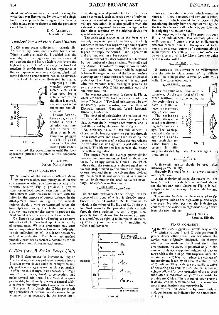
FIG. 2
214
about 20,000 ohms was the most pleasing the
writer has ever listened to. By the turn of a single
knob it was possible to bring out the bass or
treble to any relative degree to suit the particularear of the listener.
D. C. REDGRAVENorfolk, Virginia.
Another Cone and Horn Combination
I IKE many other radio fans I recently dis-*-' carded my horn loud speaker for a cone.
When listening attentively, I decided that the
cone slighted the higher frequencies somewhatso 1 dugout the old horn, which rather favors the
high notes, with the idea of using the two loud
speakers in combination. But the impedance of
the loud speakers were so poorly matched that
some balancing arrangement had to be devised.
1 evolved the scheme illustrated in Fig. 3,
employing a half-
megohm potentio-
meter, such as is
often used for a
volume control. Asthe slider is moved,one loud speaker is
cut in and one eli-
minated.
I soon found,however, that I
needed a bettercriterion than myears to place the
slider where it be-
longed, so I pluggeda pair of goodphones in the de-
tector plate circuit
and adjusted the potentiometer until the loud
speakers duplicated the pitch of the telephonereceivers.
H. D. HATCHBoston, Massachusetts
STAFF COMMENT
THEchoice of the systems outlined above
by our two readers rests pretty much on the
convenience of what you have in the way of a
variable resistor. Fig. 3 provides a greatervariation in loud speaker selection than Fig. 2
but sufficient variation can be secured with the
latter for the purpose of correct balance. In the
arrangement shown in Fig. 2 the variable
resistor should always be connected across the
loud speaker having the higher impedance,/'. e., the loud speaker that seems to produce the
most sound when the resistor is disconnected.
Mr. Hatch's system for adjusting the relative
intensities of the two loud speakers is worthyof special note. While a preference may exist
for an emphasis of high or low notes (adjustingto suit individual tastes), this is not necessarilynatural reproduction. The phone test method
probably provides as correct a balance as can be
achieved without elaborate equipment.
C Bias from B Socket Power Units
IN THIS department for November, 1927, an*
interesting item was published showing how a
B socket power device could be changed to sup-
ply grid bias voltages as well as plate potentials.In effecting this change, it was necessary to "getinside" the device, break a connection, andmake several additions. This method is quite
practicable, but there is always a general disin-
clination to "monkey" with a commercial set-up.It is possible to obtain the C bias potentials
by application of external resistors no changewhatever being necessary in the device itself.
RADIO BROADCAST
In so doing, several possible faults in the device
can be corrected, such as break down of resistors,
as may be evident in noisy reception and poor
voltage regulation. It is also possible with the
external arrangement to secure voltages other
than those supplied by the original device for
special sets or purposes.The additional device takes the form of an
entirely separate set of resistors, which is
connected between the high-voltage and negative
posts on the old power unit. The resistors are
tapped to supply the desired B and C potentialsand are mounted on a base-board.
The number of resistors required is determined
by the number of voltage outlets. We shall need
one Amsco "Duostat" to supply two variable
"C" biases, while one resistor will be requiredbetween the negative tap and the lowest positive
plate tap, and another resistor for each additional
plate tap. The Amsco "Duostat" is equippedwith two variable arms, making it possible to
secure two variable C bias potentials with the
one resistance unit.
The average arrangement is shown in Fig. 4,
which requires three fixed resistors in addition
to the"Duostat.
" The fixed resistors may be anysatisfactory power resistor, such as those of
Electrad, Amsco, Metaloid, Ward Leonard,
Durham, Carter, etc.
The method of calculating the values of the
resistors takes into consideration the probable
plate current drain through each resistor, and is
best illustrated by the example of Fig. 4.
An arbitrary value of ten milliamperes is
chosen as the loss current the current throughthe resistors over and above that drawn by the
receiver. The presence of this loss current reduces
the variations in voltage with slight differences
in load. The higher the loss current the better
the voltage regulation.The output from the average power device
receiver combination under load is about 200
volts. By an application of Ohm's Law, whichtells us that the resistance is always equal to the
voltage drop divided by the current in amperes,or one thousand times the voltage drop divided
by the current in milliamperes, it is a simplematter to determine the total resistance neces-
sary. The equation in this case is:
P. 2OO X (OOOR = =20,000 Ohms
10
So the total resistance of the "bridge" will be
20,000 ohms, 2000 of which is already appor-tioned to the "Duostat," Rt . It remains to
calculate the values of RI, R2 , and RS. To do this,
we must consider the probable plate currents
through these resistors. A 201 -A type tube,
properly biased, draws the following currents:
r. f. amplifier, 90 volts, 4 milliamperes; detector,
45 volts, 1.5 milliamperes; a. f. amplifier, 90volts, 2 milliamperes.
20,000 Q
To B + Max. on BDevice and + B Max. on Set
>
>

L. Bamherner Sc Co. Photograph
A COMPLETE COOLEY RAYFOTO RECEIVING^ INSTALLATIONThe incoming radio signals from a standard broadcasting station are received on a standard Freed-Eisemann broadcast receiver the audio output of whichis connected to the printer unit and thence to the recorder at the extreme right. Station WOR, on November 5, 1927, transmitted the first series of radio
pictures ever to be sent from a broadcasting station which were successfully received by an installation similar to this. This complete Cooley receiver
was demonstrated early in November at a special radio show held at the Bamberger store in Newark. There are only two essential units to the CooleyRayfoto receiving apparatus and they are shown on the table at the right of the loud speaker. Any good broadcast receiver can be used to pick upthe Rayfoto signals. The recorder at the extreme right is not the type usually supplied, which is furnished without the spring phonograph motor. The
commercial recorder may be attached to the turntable of any standard phonograph, thus decreasing the expense
WHY I INSTALLED A COOLEY PICTURE RECEIVER
EFORE me, as I write, is a photographof a lady. I treasure it highly. Her face is
rather indistinct; in fact, I doubt if I
could recognize her from the photograph. Al-
though the circumstances surrounding the ac-
quisition of this photograph are highly romantic
and thrilling, I neither hope, seek, nor expect to
make her acquaintance. Yet her picture will
always remain a treasured memento. It is the
beginning of a beautiful friendship, a new ad-
diction which will make my charming wife still
more thoroughly a radio widow. My new absorb-
ing interest is the radio reception of photographsand the valued curio is the first photograph ever
received on a home-assembled radio picture
receiver from any broadcasting station.
Not many months will pass before picture
tvansmission will be a regular feature of broad-
casting programs. I do not say this because I
have inside information, but because picture
reception is an inevitable step in the progress of
broadcasting. The only hindrance so far has been
the fact that no simple and inexpensive appara-tus has been available, a problem which has
been solved by the appearance of the Cooley
Rayfoto System.It is easy to speculate on the possibilities
of picture reception. Most people think of it as a
means of seeing broadcasting artists performingin the studio. Although such a use of picture
transmission is quite feasible, it is only a minor
application. Imagine a ringside description of a
champion prize-fight coming through the loud
speaker, while near-by your Rayfoto recorder is
grinding out one picture after another of the
high lights of each round. Or, imagine the
ceremonies at the take-off of the first transatlan-
tic air liner, accompanied by pictures of the
immense bird taking on its cargo, taking off with
its load, and finally disappearing in the distance.
The new medium has all the diverse possi-
bilities of tonal broadcasting and it will add a
new lure to radio reception. Perhaps my imagina-
tion runs away with me because I have just
By Edgar H. Felix
made my first radio picture, but I firmly believe
that it is only the first of hundreds, each of im-
proved quality, which I shall pick out of the air.
On November 5, 1927, WOR, the broadcast-
ing station of L. Bamberger & Co., Newark,New Jersey, put the first picture on the air from
a public broadcasting station. It was only a pre-
liminary test, to precede a public demonstration.
So far as I know, my picture receiver was the
only one, not installed at an experimental
laboratory, capable of receiving the picture. But
so great has been the interest manifested by set
builders in picture reception that I am sure
thousands of picture receivers will be in opera-tion within a few weeks.
Picture transmission by wire and radio is not a
AUSTIN G.
Bachrach
COOLEY
new art. Pictures flash across the Atlantic bythe Ranger system almost daily. The Jenkins
system has been available to amateurs for years.
The A. T. & T. has been transmitting high-
quality pictures over wire lines to all parts of the
country for some time. But most of these systems
require either expensive receiving apparatus or
more than one broadcasting channel, so that theyare hardly suited to widespread use without
considerable development.
THE COOLEY SYSTEM IS SIMPLE
THE Cooley Rayfoto system is rugged and
inexpensive. It uses but a single radio tele-
phone channel for transmission. The parts for a
picture recorder cost no more than those re-
quired for a good six-tube home built receiver.
The quality and quality in picture reception
means detail and accuracy in shading is not
below the standard of tonal reception qualitywhich we had in 1921 and 1922, a quality
sufficient to set the world on fire with a broad-
casting boom. There is no reason to doubt that
picture reception will improve as rapidly as did
tone quality in a like period. In fact, all of the
experience gained with tone broadcasting is
directly applicable to the broadcasting of pic-
tures.
The constructional details of the Cooley sys-
tem have been given completely in this magazine.
The radio element of the Cooley apparatus is no
more difficult to assemble than a two-tube radio
set. Essentially, it is a stage of audio-frequency
amplification, coupled so as to modulate the out-
put of an oscillator. It can be assembled and
wired in two hours. The rest of the work is con-
necting power supply, setting the mechanical
unit on the phonograph, and adjusting the
relay, corona discharge, and phonograph motor
speed. Mr. Cooley, in his articles, has described
these matters in some detail; my only purposein mentioning them here is to give you an idea of
how easy it is to get the Cooley receiver in
working order.

216 RADIO BROADCAST JANUARY, 1928
To receive this treasured picture of mine, we
adjusted the Rayfoto relay by tuning-in a musi-
cal program. A few moments of tinkering with a
screwdriver and the relay tripped at each loud
modulation peak. Mr. J. L. \Vhittaker, who did
most of the hard work while I looked on, had the
relay working in two minutes.
Adjusting the corona offered no special
difficulties. By tuning the variable condenser
across the oscillator coil, the corona starts as
soon as the oscillator starts going. There really
isn't anything to it. To get the modulation cur-
rent right, you plug in the meter to set the input
at the correct value. It's only a matter of juggling
the input volume control.
Synchronizing the phonograph motor when
everything else is working properly is simplewhen you know how. The phonograph motor
should revolve just rapidly enough so that the
synchronizing signal releases the drum at each
revolution. When it does so, the drum stops
with a firm click and then resumes turning
with hardly a perceptible stop. When it is work-
ing just right, the drum stop makes its click
with perfect regularity, about as loud as that of
a typewriter key against the platen. If the speedis decreased below this point, there is a drop in
the intensity of the clicks and a few may skip
entirely. That is the critical speed, when the
drum is at "zero beat" with the transmittingdrum. At that speed, the synchronizing signal
is not utilized in releasing the drum; at a slightly
faster speed, when the clicks are regular, it is in
proper adjustment.These three adjustments ,nade, and you are
ready to receive the picture. vVe got the first one
quite well, but we did not get the second one.
First the grid leak went wrong, dimming the
corona. Then the phonograph needle slipped off
the bushing. Then the relay stuck. And, finally,
the A battery went down. Of course, we didn't
get the second picture!
So, you see, there is plenty that may happenwhen you get your first picture with a Cooleyreceiver. You have reason to be proud of a suc-
cessful result. Of course, when there are plenty
of pictures on the air,
you won't have to meet
all of your troubles in
two short minutes. And,more important, is the
advantage to be gainedif you have a phono-
graph record of a Cooley
picture transmission. 1
recorded the Cooleytransmissions from WOR
The author receiving pic-
tures by means of a
Cooley Rayfoto receiver
on a high-quality Dicta-
phone. By reproducingthese records with an
electric pick-up, everyelement of the picturereceiver can be put in
working order before
transmission begins.Such records can prob-
ably be used for trans-
mission purposes so that
all the broadcastingstation needs to put
Cooley pictures on the
air is a phonograph record and a phonograph.
THE GATEWAY TO TELEVISION
PICTUREtransmission is the gateway to
television and every red-blooded experi-
menter longs for the opportunity to becomefamiliar with its problems by actual experience.
The Cooley system sends the picture in one
minute and to increase this speed of transmission
sufficiently to get motion pictures requires a
thousandfolding of this speed. Considering the
magnitude of the improvement required, it
seems impossible that the Cooley system can
TWO PICTURES RECEIVED ON A RAYFOTO RECEIVERThe picture on the right shows the effect of improper adjustment of the oscillator in the Rayfoto printerunit. The white streaks are produced when the oscillator suddenly stops oscillating. The left-hand
picture indicates the improvement in results after the oscillator has been adjusted. For best results
the oscillator should not be tuned exactly to the point at which the maximum corona discharge is
obtained since, when so adjusted, it is rather critical and easily stops oscillating. The variable con-
denser controlling the oscillator circuit should always be slightly detuned from that point at whichmaximum corona discharge is obtained
ever be the basis for television. A fundamentaland startling invention is necessary before so
great an increase of speed can be hoped for.
There have been demonstrations of television
already, but all use electrical machinery so
complex and expensive that the tests really
proved that television is not .yet a practical pos-
sibility with our present knowledge.Someone will some day accomplish the es-
sential invention to make television practical.
Very probably the discoverer will be someonewho has worked with picture transmission. Andthe man who does make television possible will
go down as one of the world's greatest inventors.
Thousandfolding the speed of any process is a
large order. But remember that only twenty-five years ago, when radio telegraphy made its
appearance, the detector used was a glass tube
filled with iron filings. Electromagnetic wavescaused these iron filings to congeal or cohere so
that the current from a local battery flowed
through them. This operated a sounder. The iron
filings were agitated by the clapper of a bell so
that they would de-cohere or interrupt the bat-
tery current as soon as the radio wave ceased
flowing through it. With this crude apparatus,transmission of two, three, four, and five words a
minute was the maximum possible. Ranges were
matters of a few miles.
Then came the invention of Marconi's mag-netic detector. This greatly increased both
speed and range. And then the really revolution-
ary vacuum tube. Now, with high-speed radio
telegraphy, we send thousands of characters aminute. From many of the long-wave, trans-
oceanic stations, you can hear the myriad of dots
and dashes, so rapid that you cannot distinguish
between them. The step from the coherer to
radio telephone transmission and reception is no
greater than that necessary from telephotog-
raphy to television. Undoubtedly, someone will
make that essential invention to make television
possible and 1 hope it will be an American
amateur experimenter, who has enough vision
to see in the crude, simple, telephotographic ap-
paratus available to him to-day the possibilities
of the great new science and art of the future.

ssin
Every Conceivable Source of Radio Interference Is Considered, Remedial Suggestions Being
Offered Farm Lighting Plants, Railway Signals, Telegraph Lines, Stock Tickers, Street
Railways, and Interference Originating in the Receiver Itself, Are Taken up in This Chapter
By A. T. LAWTON
THEstudies made by the author in the
elimination of interference have been so
extensive that it would be hardly possible
to combine the various chapters in one issue.
An endeavor has been made, however, to elim-
inate cross references so that each article in
the series may be complete in itself. The forms
of interference covered in the two previous chap-
ters, printed in the September and November,
1927, issues of RADIO BROADCAST, dealt with
interference originating at the following sources:
Oil-burning furnaces, X-ray equipment, dental
motors, motion-picture theatres, telephone ex-
changes, arc lamps, incandescent street lamps,flour mills, factory belts, electric warming pads,and precipitators. The information printed re-
sults from a two-and-a-half-year study by the
author in more than 132 cities. The first form of
interference considered in the present chapter,is that originating in farm lighting plants.
FARM LIGHTING PLANTS
INTERFERENCE from this source is confined* to rural districts. The characteristic click,
click, corresponding to the ignition spark, re-
veals the source at once; rarely do we get trouble
from the commutator.
This continuous clicking is very loud on near-
by radio receivers and because of the large num-ber of plants in operation in communities not
served by electric power companies, the total
interference is very annoying.
Complete elimination of the disturbance
created is a relatively simple matter. Nearly all
these plants, being bolted down to a wooden
platform, are insulated from the ground and two2-microfarad condensers in series, midpoint con-
nected to the engine frame, and bridged across
the outgoing d.c. feeders, will clear up the click-
ing. Ground connection of the series wire should
not be made to a water pipe or earth rod in this
case. Even i-microfarad condensers will be
found suitable for small plants.If the engine bed is of concrete or the plant is
grounded in some other way, complete elimina-
tion is not obtained by the above method al-
though the reduction (about 80 per cent.) is
material. The remaining interference is not likely
to be serious. However, where it is desired to
clear this out also, choke coils should proveeffective.
It is not uncommon to find the exhaust pipe of
such plants carried to a muffler drum in the
ground; such a connection to earth offsets the
effect of the condensers and more satisfactory re-
sults will be obtained if this pipe is cut and a
section of asbestos or other suitable piping in-
serted.
Further experimental work is required in the
cases where Electrical Inspections call for the
grounding of small lighting plants. Possibly a
fine wire choke coil, say, of No. 26 wire, bridged
by a standard lightning arrester, would be
satisfactory, the coil preventing the accumula-
tion of any static charge and the arrester takingcare of any abnormal surge superimposed on the
system from outside sources.
As a precaution, all leads around the plant
proper, either high- or low-tension, should be
cut as short as possible.
Where one or two of the storage cells are used
to operate a radio set as well as light the residence,
complete elimination of the trouble for that
particular set becomes difficult.
Prior to arriving at suitable preventivemeasures in the various plants investigated, ex-
periments were carried out directly on the igni-
tion system but all methods tried proved of noavail. In the case of "make and break" type
ignition, condensers applied directly to the igni-
tion system stalled the e'ngine, apparently neu-
tralizing the effect of the inductance coil, but
were quite effective on the outgoing lines and, of
course, did not interfere with normal operation.In all cases attachment of the condensers is
made at the switchboard, under the same ter-
minals to which the two lighting mains are con-
nected.
RAILWAY SIGNALS
RAILWAY"wig-wag" signs and crossing
bells give rise to heavy clicking radio inter-
ference. Fortunately, their periods of operationare limited, but where the trouble is material
it can be cleared up by shunting the operatingcontacts with a resistance of about 350 ohms.This applies to low-voltage d.c. operated bells
and signals.
To Key0.5 mfd.
Condensers Chokes^
n000000000(7
For types operating on 400-600 volts it is
necessary to bridge each individual set of contacts
with a resistance of the above order.
The vibrating reed type battery charger used
in conjunction with these signals is a real offender.
Interference from this source has given rise to a
large number of complaints but, generally speak-
ing, railway companies are averse to tackingon any surge traps to this equipment and in the
dozen or so cases cleared up, the operating com-
pany took the chargers out bodily and sub-
stituted a type which is silent so far as radio
interference is concerned.I
LAND LINE TELEGRAPH AND STOCK TICKERS
RAPIDclicking interference from the above
equipment is a serious matter in towns andsmaller cities. Not that there is less telegraph
activity in the larger centres, but in the placesreferred to a comparatively greater number of
residences and radio dealers are located in the
vicinity of the telegraph offices.
Normal operation of the keys and repeatersset up a vigorous highly damped wave whichbreaks in on practically any setting of the dials
of the average radio set. The clicking from stock
tickers is severe even where the wires are en-
closed in lead-sheathed cable.
Since it is necessary to apply suppressive meas-ures to each individual line, the factor of cost
looms large when we consider the number of
lines entering the average city office. Whereonly a few lines are concerned it is usual to placea i -microfarad condenser across the key con-
tacts inserting in each condenser lead a resistance
of about 20 or 30 ohms.
Strictly speaking, only one resistance unit is
required but it makes a very great difference
which contact of the key this resistance lead is
connected to. If the condenser alone is used, re-
duction of the interference may be noted butthe resultant arcing at the contacts is prohibitive.It is ordinarily supposed that the condenser in
this case should absorb the spark; rather, it
turns the spark into an arc and resistance is re-
quired to overcome this.
We must remember that many variables enter
here; at a given time, one leg of the key may beto ground and the oth'.r leg to line, positive or
Line
FIG. I
The circuit employedto eliminate interference
caused by key clicking.An obstinate case waseliminated by applica-tion of a surge trap, as
shown in this diagram
Chokes- 130 turns No.26 D.C.C. wire on wooden core 15/diam.
217

218 RADIO BROADCAST JANUARY, iga8
negative. Again, the key may be cut in on a
through line, positive or negative either way,and these conditions are likely to be re-
versed many times in the course of a day
through jack plugging operations at the switch-
board.
In most cases these clicks are unreadable; theyoccur at the break of the key, not on the closing
of the circuit, but in the immediate vicinity of
a telegraph office, radio interference may be noted
from the local or sounder circuit. This is readable
and can usually be eliminated by bridging the
relay contacts of the local circuit with a one-half
microfarad condenser without any series re-
sistance.
Occasionally, complications enter into the
situation, making necessary the use of full surge
traps. An obstinate case of key clicking was
cleared up only after applying the surge trap
described in Fig. i.
Another difficult case, in connection with a
set of repeaters, required choke coils as described
in Fig. 2 in each line and o.5-mfd. condensers,
series arrangement midpoint grounded, across
the repeater contacts.
Duplex and quad circuits require individual
treatment; much experimental work is required
before standard eliminators can be recommendedfor these and the various types of stock tickers
in daily operation.
RADIO RECEIVERS
MUCHof the so-called inductive interference
has its origin in the broadcast listener's ownset. It might be due to any one of the following
causes:
(i.) Loose antenna or ground connections will
give rise to serious clicking noises whenshaken by wind or other agency.
(2.) Loose or corroded connections at the Abattery will cause flickering of the tubes
and consequent clicking.
(}.) Internal defects in any one cell will cause
harsh grating noises. This can be checkedwith a telephone transformer and pair of
headphones, the secondary of the trans-
former being connected to the battery and
primary to the phones.
(4.) Defective B batteries cause a "chirping" or
clicking interference. It doesn't follow that
because a B battery registers full voltage,
22! or 45, that it is in good condition. One
high-resistance cell of the many incorporatedin this battery can render the battery unfit
for use although on open circuit it reads upto full strength.
(5.) Oxidized contacts of the tube prongs or
spring contacts of the sockets are fruitful
sources of trouble. These should be scraped
occasionally and the spring strips pulled upgently to insure that good contact is beingmade.
(6.) Broken lead-in wires cause poor receptionand clicking noises. Naturally, a lead-in
wire must be insulated where it enters the
building but the practice of using covered
wire all the way down from the horizontal
portion of the antenna is not to be recom-
mended. From swinging in the wind, this
wire often breaks inside the insulation but
is held up by the fabric so it appears to be
continuous whereas the wire itself is sepa-rated an eighth of an inch or more.
(7.) Concealed house light wiring in the walls
will cause humming noises if the radio set is ,
installed close up to such partitions. This is
especially noticeable in the case of single-circuit receivers.
In the case of abnormal humming it is
probable that the main supply line (three-wire system) is badly out of balance or the
wrong side of the house lighting system is
grounded. This latter will not necessarilyblow the fuses.
A and B supply devices designed for
sixty-cycle supply will also give some similar
trouble when used on twenty-five cycle lines.
Various stray noises will, of course, result from
defective tubes, shaky splices, poor construction,
connections soldered with acid flux, etc. Before
assuming that any given interference comes
from the outside, broadcast listeners should dis-
connect the antenna and ground wires and note
if the interference weakens or disappears. If it
does, the source of the trouble is outside. If it
remains the same and is not responsive to tuning,
the trouble, nine times out of ten, is in the set it-
self.
Unshielded sets may pick up outside inter-
ference without the antenna or ground being
attached, but a decided weakening will be ob-
served when these are disconnected and this is
sufficient proof that the disturbance is not in-
ternal.
As a test, the house lighting supply switch
should be opened for a moment. If the inter-
ference disappears coincident with this, all lights
and electrical apparatus in the residence should
be checked over for possible faults. A lamp loose
in its socket can cause quite a lot of trouble.
Partial shorts in the interior wiring will cause
trouble over a fairly wide area; such a case
-_*
A-*" B-%" C-%r D-2V E-%"Hardwood Bobbin. approx 300turns No.22 (about 125 ft)
FIG. 2
occurred recently where a long nail driven in an
attic floor brought a concealed power wire in
contact with the grounded plumbing.
ELECTRIC STREET RAILWAYS
INTERFERENCE from this source presents a
1 problem for which no really satisfactory solu-
tion has been found. Without question, manyradio sets are unnecessarily interfered with
by this agency and in such cases relief is possible.
The steady interference under a street-car line
is violent; fifty feet either side of this it is almost
negligible. Only when cars go by or some very
abrupt alteration of the line energy values occurs
do we get trouble at this distance.
The following actual test is interesting: On a
radio set, the antenna of which ran parallel to a
car line, broadcast programs were rendered
valueless as mediums of entertainment but whenthis antenna was changed to run at right angles
to the line, good reception became possible. Theeffect was decided.
If your antenna is at present installed at the
front of the building, facing the car line, shift it
to the rear as far as possible. If conditions per-
mit, run it at right angles to the line of inter-
ference. It is surprising what a difference one
or two feet variation in the plane will make
here and we suggest when installing, permanently
fixing one end of the horizontal portion and tem-
porarily attaching the other end of the horizontal
part to a pole which may be carried backward
and forward on the roof to test out the exact
position of minimum interference.
Relative intensity of the interference is noted
at each setting and a permanent pole fixed at the
proper point. We must remember that lighting
and power circuits nearer the residence than the
trolley feeder are concerned in transferring this
disturbance to the antenna, and distortion of di-
rection is pretty sure to occur.
Sparks at the trolley wheel cause clicking inter-
ference; large arcs cause none. The bigger the
flash, the less the interference. Cars going upgrade on full power cause decidedly less inter-
ference than cars coasting with practically all
power off, only the lights or heaters being in
operation. Trolley shoes are no improvement over
wheels. Catenary suspension makes no difference.
If the positive lead of the station generator
goes direct to the trolley wire, interference will
probably result. If this lead goes to the series
field winding first, the free end of the series field
going to the line, the choking effect of the coils
tends to suppress any commutator interference.
In addition to checks on the usual 6oo-volt
d. c. systems, observations were carried out on:
(a.) Pantograph System, 6600 volts a.c. coppertrolley wire.
(b.) 1 5oo-volt d.c. system using shoes. Coppertrolley.
(c.) 24Oo-volt d.c. pantograph. Copper trolley,
(d.) ijoo-volt system d.c. shoe contact. Entire
system steel trolley wire.
A great many variable factors entered into the
results and for scientific purposes the data ob-
tained are not considered satisfactory. Muchtime and effort and expense have been devoted to
the whole problem of interference from electric
railways but, so far, results have not been very
encouraging.It must not be concluded, however, that the
proposition is hopeless; greater efforts are beingmade in every city to keep the rail bonding in
good shape and it is probable that more careful
attention to car motors and equipment generallywill tend to alleviate the situation.
Peculiar effects are often observed on radio
sets installed in the vicinity of a car line. It is
not uncommon to find that a passing car, even
when causing little or no radio interference, will
"take away," temporarily, the program beingreceived. As soon as the car moves away a few
hundred feet the program comes back, without
any alteration of the set tuning whatever.
Again, in two widely separated instances, andsome distance away from the car lines, the dis-
turbance on residence radio receivers amountsto a continuous loud roar. Immediately outside
both residences no interference can be picked upon a standard six-tube super-heterodyne receiver.
Evidently this was a case of electrolysis since
an exploring coil on the water piping indicates
fluctuating current in the plumbing system.Concealed pipes and wiring in these residences
carry the surge also and loop reception is prac-
tically no better although the ground wire to the
water pipe is cut off.
One of the most curious and perplexing cases
of radio interference that we know of had its
origin in an electric street railway system. This
particular noise affected only three residences,
all fairly close together. All efforts to locate the
trouble failed but the plumber solved the prob-lem. It so happened that the drain pipe of the
centre house became blocked; on digging this
up it was found to be full of a fibrous growthand at a crack in the pipe a mass of roots had
come through and grown out in the direction of
the railway tracks, close up to the rails, in fact.
This offshoot evidently served as a conductor
to electrify the plumbing fixtures of the three
houses concerned and as the radio set groundswere attached to this, every variation in the rail-
way line voltage set up a disturbance on the
radio receivers. When the drain pipe was cleaned
and replaced, all interference disappeared.

The Listeners' Point of View
ARE PROGRAMS GOING IN THE WRONG DIRECTION?
lOMETlMES when we sit ourself downto pound out this monthly manifesto
concerning matters radio, we attack the
job with great gusto and enthusiasm. We are
filled with a vast faith in radio's achievements
and possibilities and garner a certain amount of
personal satisfaction in making our small critical
contribution to radio's great ends.
There are other times when we entertain grave
misgivings as to whether the subject is actually
worth the fifteen clean sheets of typewriter
paper we employ to comment on it. Such doubts
assail us this very minute. Probably when we are
effusing enthusiastic utterances about radio
entertainment we are writing romance, and to
admit that it is pretty punk is simply to be realis-
tic. Though if you be of the other turn of mind
you may claim that it is the former that is realism
and that the latter is rank pessimism which
suggests an appropriate variation of Cabell's
ingenious epigram: The optimist thinks that radio
has now reached the greatest heights of achieve-
ment. The pessimist, alas, is afraid that he's
right!
Whatever roseate promises radio may have
seemed to have held in the past we are at present
thoroughly convinced that things have reached
a sorry pass and that radio is standing still
smug, self-satisfied, and inutterably banal. Onerobin does not make a summer and the indubi-
tably good program to which you may point here
and there (only too infrequently!) isn't enoughto raise radio to the standard it ought to be
maintaining.If two years ago someone had told us that by
the end of 1927 programs would have only at-
tained the level they now actually occupy wewould have pooh-poohed him as a person in-
capable of reading the signs and portents. At
the rate things were progressing in 1925 there
was every indication that another two years
would find us surfeited with high-class program
material, of such high standard that we would
be loath to absent ourselves from our receiving
sets for two nights in a row.
As we look back several years, the greatest
hope for improved programs then seemed to lie
in the ever increasing number of sponsored pro-
grams. Great industries were going to start pour-
ing their gold into the radio stations in paymentfor indirect advertising more properly, radio
publicity and great things were going to result.
Herein was the solution of all our difficulties:
without government operation; without levying
of taxes; without philanthropic financing, wewere going to lead the world in program stand-
ards by utilizing our great American asset BigBusiness.
Well the dismal fact of the matter is that none
of these things has come about. And the ironical
conclusion to which we are forced is that the
rise of the sponsored program is responsible for
the stand-still that radio has reached at the dawnof this year of grace 1928. In fact, stand-still is
putting it mildly; the state of affairs is more
exactly a retrogression. All the money, all the
ingenuity, and all the labor that is being devoted
to the designing of programs is being diligently
devoted to efforts in the wrong direction with
the result that radio is going to the dogs at a
breakneck speed, so rapidly in fact, that to check
it will require no little effort.
By JOHN WALLACELET US LOOK AT THE GUIDE POSTS
\A7HAT is the right direction? It would seem' that program makers are too embroiled in
their business to glance at the guide posts, too
pressed by the strenuous and unceasing job of
making programs to take a moment or two off
for a little rational reflection on what their jobis all about. They persist in refusing to take
account of the fact that radio is a new medium,a unique medium and, like any other medium,endowed with its peculiar limitations and
peculiar possibilities. Pig-headedly they persist
in attempting to reconcile with their duties the
traditions of the drama, the opera, the music hall,
and the vaudeville stage. This observation has
Radio Times, London
IGOR STRAVINSKYThe British Broadcasting Company, on a recent
Sunday afternoon symphony program, presentedthe modernist composer, Igor Stravinsky, con-
ducting a program of his own works. This is
an event in radio annals. True, Stravinsky hasbeen "outmoderned" by a group of still youngercomposers but his compositions are still quite far
in advance of the popular taste. It's likely that
no American station would have, nor will havefor many years, the temerity to present a pro-
gram of such dubious popular appeal. This does
not indicate that the Britisher is any more
sophisticated in his tastes than the American;it is our guess that the B. B. C. is enabled to
essay such a high-brow program simply because
it is non-competitive. On Mr. Stravinsky's pro-
gram appeared the Overture to Mavra, the
Suite from the Fire Bird and a Concerto for
Pianoforte with Accompaniment of WindInstruments. The latter was a premier English
performance. The above portrait is from a draw-
ing by the famous French artist, Picasso.
been made often before. We are a trifle abashed
at shouting the same tune again. But probablyit will have to be stated many times more^-and certainly by others than ourselves before
it sinks in.
Without annoying you by enumerating radios'
219
limitations, which you know as well as we (unless
you happen to be a program designer, in which
case you probably don't), we will proceed to the
proposition that the one species of entertain-
ment that radio is by its intrinsic nature best
fitted to put across is instrumental music.
Music is the only existing mode of entertain-
ment that can be assimilated solely by the un-
aided ear. The radio (together with the phono-
graph) is the only existing entertainment device
which can reach nothing but the ear. Obviously
they were made for each other! They should be
joined in holy wedlock and wander hand in
hand through the new mown hills, happily ever
after.
Instrumental music should be the backbone
of the radio program; it should predominate
every program; it should be the piece de resist-
ance with all the other little absurdities of broad-
casting arranged around it like the potatoes
around a roast beef. Plays, where you can't see
the players, speeches where you can't see the
speakers, comedy, where you can't see the
comedians all such like stuff is mere piccalilli
and sauce.
So the business of broadcasting is music.
And by music we mean music at its fullest reali-
zation, which is that of the instrumental en-
semble the symphony, the little symphony,or the chamber group.
In the field of the representative arts are
many different mediums water color, etching,
caricature, wood cut, lithograph, miniature, pen
drawing, fresco, and countless other specializa-
tions. But it is finally in the oil painting that
graphic art finds its complete expression. Beside
it all other artistic endeavors fall into compara-tive insignificance. It contains within itself the
whole total of their qualities and infinite other
ones of its own.
A perfect analogy exists in music. Vocal music
is all right in its way, as are also organ recitals,
piano gymnastics, jazz bands, and marimba-
phones. But they are all dwarfed by the sym-
phony orchestra. The orchestra not only can do
all the things that they can do, but can do them
better and with its great musical resources can
secure added effects that they can't possibly
aspire to.
Of course it is always necessary to get back to
the cold fact that, in America at least, the station
manager's only business is to give the listeners
what they want. But don't they want orchestral
music? There has been much talk about how the
taste of the listening public has been elevated
by radio and much proclaiming that Mr. AverageCitizen has reached a stage of enlightenmentwhere he can actually enjoy serious musical
compositions. We are inclined to believe that
this is true. Moreover, there are thousands of
people in the country who needed no "educat-
ing" but who already liked such music. It seems
fair enough to deduce that genuine music is
the "what-they-want" of a sizable section of
listeners and potential listeners.
In view of the fact that orchestral music is the
best thing that a station can put across, and the
best thing that a listener could listen to, it seems
fair enough further to deduce that there ought to
be a certain amount of it in the air of an evening,available for such persons as wish to seek it out.
But is it there?

220 RADIO BROADCAST JANUARY, 1928
THE HORRIBLE EVIDENCE
BYWAY of confirming our suspicion that
there isn't, we sat ourself down at our
receiver the other night and proceeded systemati-
cally to get a cross section of what was on the air.
At 8:15 p. M. (Central time) we started at the top
of the dial and worked our way patiently to the
bottom, recording everything that was going on
within our receiver's range. The stations en-
countered extended from Colorado to Texas to
New England. At 9:35 P. M. (Central time) the
chore was concluded, and if you entertain anydelusions that there are a lot of fine things on the
air awaiting the turn of a dial, gaze at the cold
and cruel statistics we found on our tablet:
1 JAZZ PIANO, playing "Ain't She Sweet."
2 JAZZ ORCHESTRA, dance music.
3 COUPLE AT A PIANO, wise cracks, request
numbers, ballads.
4 SENTIMENTAL SONGS, "Sweetheart of SigmaChi," etc.
5 SOPRANO, singing the Brindisi from "Lucre-
zia Borgia."6 BARITONE, singing unidentifiable ballad.
7 SERMON, of the vocal-cord-splitting variety.
8 TENOR, popular ballad, "I'll Forget You."
9 DANCE ORCHESTRA, playing "Rio Rita."
10 OLD TIME FIDDLING, with "swing yourpartners," etc., interpolations.
1 1 STRING TRIO, playing semi-popular airs.
12 CHORAL GROUP, in the finale of a light
opera.
13 SOPRANO, singing the Shadow Song from"Dinorah."
14 SOPRANO, singing "Just a Wearyin' for
You."
15 CHURCHILL SISTERS, singing "Say AuRevoir but Not Good-bye."
16 SOPRANO, singing some light ditties in
French.
17 DRAMATIZATION, of Rip Van Winkle.
18 TENOR, solo.
19 STRING TRIO, playing Saint-Saens' "Swan."20 WEATHER REPORT.21 DANCE ORCHESTRA.22 NOVELTY SONG, with banjo.
23 HAWAIIAN GUITAR AND MANDOLIN, duet.
24 TRAVEL, talk on Starved Rock, Illinois.
25 FEMALE, reciting poetry.26 MALE QUARTET, singing
"Bye and Bye."
27 PRIZE FIGHT.
28 BRASS BAND, playing "Moonlight Wonder-
ings."
29 JAZZ ORCESHTRA.
30 TENOR, singing Welsh folk songs.
31 TENOR, singing popular ballad, "Lone-some."
32 PIANOLOGUE.
33 TENOR, singing sentimental ballad.
34 VIOLINIST, playing Beethoven Opus 12
Number i.
35 TENOR. "A Robin Sings in the Apple Tree."
36 TRIO, playing semi-classics.
37 ORGAN, "Pale Hands I Loved," etc.
38 BASS, soloist.
39 DANCE orchestra, "On a Dew Dew DewyDay."
40 FEMALE duet, sloppy ballad.
41 MALE CHORUS, college songs.
And there you are! Nowhere was the orchestral
program we had set out in search of. Twenty of
the forty-one programs were vocal, practically
fifty per cent.! And this in spite of the fact that
vocal transmission is one of the lesser effective
things broadcasting is capable of. Only three of
the programs encountered seemed to hold any
promise of suiting our mood of the moment,numbers 5, 13, and 34. But a return to these dial
positions found the stations already shifted to
something trifling.
But perhaps, we reflected magnanimously, we
had picked out the wrong hour of the evening.
So the following night we repeated the pro-
cedure, commencing at 7:15 P. M. Central time,
and running through to 8:20. Behold our second
log:
1 SOPRANO, singing Nevin's"Rosary."
2 DANCE ORCHESTRA, jazz.
3 BARITONE, solo "Young Tom o' Devon."
4 JAZZ ORCHESTRA.
5 DANCE ORCHESTRA.6 DANCE ORCHESTRA.
7 DANCE ORCHESTRA (what, another!).8 ORGAN, Mendelssohn's A Major Organ
Sonata.
9 MALE QUARTET, "Back Home Again in
Indiana."
10 BANJO, solo with piano accompaniment.1 1 TALK, on something or other.
12 PIANO, solo.
13 NEGRO SPIRITUAL, "I Heard From Heaven
To-day."14 PLAY, Julius Caesar.
15 SMALL ORCHESTRA, playing "Gypsy Sweet-
heart."
16 BAND, playing march tune.
17 VIOLIN, Schubert's "Ave Maria."18 VOCAL DUET, semi-popular songs.
19 BIBLE READINGS.20 TENOR, singing sloppy ballad.
21 TRIO, playing light stand-bys.22 COUPLE, singing novelty songs about sweet
mammas.23 DANCE ORCHESTRA.
24 SPEECH, by some labor leader.
25 STRING QUINTET playing Handel's WaterMusic Suite but, alas, even as we listened,
this changed into a soprano solo!
Such Was our clinic sixty-six cases examined
over a period of two hours and twenty minutes
of the most favorable broadcasting time of the
evening. It may be objected that we didn't
examine all the programs of all the stations dur-
ing that time period, but we see no argument to
show that the cross section we observed was
other than representative. Representative, for
the most part, of a lot of inanities that only the
veriest imbecile, with the meagerest amusementresources conceivable, could dignify with the
name of worthwhile entertainment.
Of these sixty-six programs not a single one
was orchestral. The few trios we ran across were
simply doing their five or ten minute/ turn on a
well scrambled variety hour.
WE DON'T NEED SO MUCH VARIETY
T"*HIS frantic search for variety is one of the*
silliest things in the whole radio broadcast-
ing business. Variety has been set up on a
pedestal as the one goal to be achieved. Themeans used to secure it are devious and dull.
Variety is necessary, of course, but there are
other sorts of variety than that of the vaude-
ville show. Program directors do not realize that
music, real music, contains within itself all the
variety that is necessary. If program arrangers
only realized it, their job has already been done
for them by the great composers.
Practically every hour of program furnished
by the broadcasters to-day is a variety program.And where every program is a variety programwould it not be a variety to introduce a programthat is not a variety program?We throw out the foregoing sound suggestion
to whomsoever chooses to make use of it (fearingthe while that no one will).
To the rising tide of sponsored programs is
due the blame for the overwhelming number of
variety programs which is rapidly reducing radio
t6 the level of a gigantic and worthless vaudeville
show. In any schedule of entertainment it is the
light frivolous item, introduced to break the
monotony, that is the brightest thing on the
program. This principle is borne in mind by the
advertiser when he decides to produce a broad-
cast program of his own. He will make his pro-
gram snappy and ever changing, he reasons,
and thus make it stand out in high relief against
all the others. Unfortunately every other ad-
vertiser goes through precisely the same sort of
reasoning. The result is that sponsored programsare all as alike as peas in a pod, and no pea is
any more novel or attention compelling than its
neighbor on the left or on the right. All are deal-
ing in olives and chilli sauce, nuts and caviar.
None is willing to supply the meat of the repast.
This meat must be orchestral music of solid
musical worth.
If broadcasting, considering it as a whole, were
maintaining a proper balance in its offerings
a thing it must eventually do or go out of busi-
ness it would be possible to find good music,
played by competent orchestras, at at least ten
places on the dial at any hour of the evening. Its
present condition, that of having no respectable
music to offer, is certainly not a healthy one.
Some stations used to maintain fair sized
orchestras as a staff feature, but their number is
rapidly diminishing the very reverse of what
should have happened. If radio had progressedin its proper channel we would now have some
ten or twenty symphony orchestras throughoutthe country bearing as their titles the names
of the stations which organized them, and being
secondary in musical importance only to the old
established symphonic societies. It is expensive,
certainly, to maintain a large orchestra but whenit comes to hiring dance bands or opera singers
expense seems to be no important item to the
broadcasting stations.
If expense is not the drawback it must be that
there is still a lingering fear that not enough
people will listen to a highbrow orchestral broad-
cast to make it worth while. This fear, as wehave already stated thirteen different ways, is
ungrounded. The Damrosch programs (an excep-tion we advance in further proof of our point)
seem successful enough. And witness the way the
populace is clamoring for more sophisticated
orchestration of its dance music. They go wild
over Paul Whiteman's rendition of "When Dayis Done." If they like this why wouldn't they
enjoy the compositions of Stravinsky and others
of the modern school. Katscher's piece is simplya shoddy and ineffectual mimicking of the works
of these composers. There are tunes in the
Beethoven symphonies as simply melodious as
anything Victor Herbert ever wrote. No one
who likes jazz effects could fail to be pleased byCasella, for instance, or Sowerby. We defy any-one but the stupidest moron to listen to the first
movement of the Cesar Franck symphony with-
out craving to'
hear it repeated. Schelling's
"Victory Ball" could sweep any Rotarian off his
feet. The use of the human voice in Bloch's
"Symphony Israel" is incomparable, but not
incomprehensible. Ravel's "Waltz" makes those
of the light operas tame indeed. Tschaikowsky's"Manfred" symphony, for those who would
weep, is forty times more lugubrious than
"Hearts and Flowers." The name of Bach could
terrify no one who had heard Abert's arrange-ment of his Chorale and Fugue. Scriabin's
Third Symphony is of such emotional ferocity
that it could emotionally unstabilize a brassy
monkey. And as for soul satisfying harmony,better than any organ chords is the passacagliathat concludes Brahms' Fourth Symphony.

RADIO BROADCAST PhotographUSED IN THE LABORATORY
The photograph of the vacuum-tube voltmeter shown schematically in Fig. 2 indicates a simple breadboard layout. The equipment includes a Yaxley
potentiometer, a Pacent rheostat, an Alden socket, Mountford and Crescent resistances, a Sangamo "Parvolt" condenser, and several Fahnestock clips
A VACUUM-TUBE VOLTMETER
INTHE study of radio-frequency phenomena,
experimenters have always been more or less
handicapped by their lackof accurate measur-
ing instruments. It is a simple matter, compara-
tively, to build a meter that will cover a consider-
able range when one works at 60 cycles, or at
fairly high values of current and voltage, but let
the research student attempt to measure currents
at a million cycles and of a few microamperes, or
voltages of a few microvolts, and his problem has
increased in difficulty many fold.
The advent of the vacuum tube has madematerial progress possible in the realm of radio-
frequency measurements, so much progress, in
fact, that it is now possible to buy a book that
deals with nothing but measurements at fre-
quencies far beyond those used for household
purposes, and at values of current and voltage
that are prefixed by the word "micro." Such a
book, Radio Frequency Measurements, by E. B.
Moullin, was reviewed in RADIO BROADCAST for
October, 1926; no serious experimenter can afford
to be without it.
In the present-day radio laboratory there will
generally be found, on one hand, a vacuum tube
generating currents and voltages of practically
any frequency and any amplitude (the modulated
oscillator described in the June, 1927, RADIO
BROADCAST is an example), while on the other
hand is another tube, perhaps exactly similar in
type to the generator, the purpose of which is to
measure the output of the first tube.
This latter tube, variously known as a "peak"voltmeter, or a vacuum-tube voltmeter, is the
laboratory's most versatile and useful instrument.
It can be used to measure voltages and currents
of any amplitude and frequency, to measure the
voltage or power amplification of audio- or radio-
frequency amplifiers, the field strength of distant
stations, the high-frequency resistance of a coil
or condenser, as a level indicator in broadcasting
stations or remote control stations anywherein fact where a meter is required which takes so
little power from the circuit being measured that
its presence causes no error in measurement.
Briefly, the vacuum-tube voltmeter is a tube act-
ing as a detector, or distorting device, so arrangedthat alternating potentials on the input may be
read as direct current in the output. Unlike other
translating mechanisms, the vacuum-tube volt-
meter has no moving parts, there is little to wear
By THE LABORATORY STAFF
out, it has nothing in its construction that is not
easily replaceable and, best of all, it can be madeto consume almost no power from the source to
which it is attached.
Why is such an instrument necessary, and
what are its particular qualifications comparedto voltmeters with which we are all familiar? Let
us suppose, for example, that we wish to measure
the voltage delivered by a dynamo which will
light a hundred 4O-watt lamps, that is, will deliver
4000 watts, or 4.0 kilowatts. Suppose our ordin-
ary moving-coil voltmeter has a resistance of
10,000 ohms and that when placed across the
terminals of the dynamo it registers 100 volts,
how much current and power does it take from
the generator?Ohm's law, which states that the number of
amperes flowing in a circuit is equal to the voltage
of the circuit divided by its resistance, tells us
that o.oi amperes will flow, and when we multi-
ply this value of current by the voltage across
the meter we find that the product, i.o watt, is
the actual power required by the meter to give
the proper deflection. Now this one watt is a verysmall part of the power that can be delivered bythe dynamo, one four-thousandth as a matter of
fact. It will readily be seen that the error of read-
ing of the meter, due to the current it consumes
itself, will be so small in this case as to be negligi-
ble.
But suppose our dynamo still had a terminal
voltage of 100, but was so small that it could
supply only one watt of power? How can we
measure its output? It is at once obvious that
xu

222 RADIO BROADCAST JANUARY, 1928
Builders of plate-supply units, and owners of
power amplifiers, who have placed a milliam-
meter in the plate circuit of the power tube, and
watched its deflections under strong signals, have
possessed the essential part of a vacuum-tube
voltmeter an overloaded tube. Whenever a
signal came along which was greater than the Cbias could handle, the average plate current
changed and caused variations of the milliam-
meter needle.
But why does the needle wobble?
The normal plate current, as indicated by the
milliammeter, is fixed with a fixed value of grid
bias and a given plate voltage. When small a.c.
voltages (the incoming signals) are placed on
the grid circuit, the C bias is changed accordingly
and in the plate circuit appears a magnified rep-
lica of these input voltages. In other words, the
actual voltage on the plate of the tube varies
with the input grid-filament voltage and natu-
rally the plate current changes accordingly. If
these changes are rapid and symmetrical, so that
an increase in current is followed by an equal de-
crease, the average value of the plate current
will remain the same and the milliammeter
needle does not move. It is these a.c. plate
currents which are amplified and which produce
signals; the d.c. current is only a necessary and
not directly useful part of the process.
If the changes in plate current are not sym-metrical with respect to the value when no a.c.
input is applied, the average value of plate
current is different, and the plate milliammeter
needle jumps about if this average value changes
rapidly. The relative amount of plate current
change, and whether it decreases or increases
from the steady d.c. value with no input, depends
upon the fixed C bias, so that we can make the
complete unit, tube and meter, into a sensitive
indicator of small a.c. voltages if we choose the
plate and grid voltages correctly.
(i-Amps
FIG. 2
Here is the circuit diagram of the vacuum-tubevoltmeter described in this article. The addi-
tional apparatus not shown in Fig. I constitutes
a bucking-voltage device to keep the normal
plate current out of the microammeter and, of
course, the filament battery and rheostat
The vacuum-tube voltmeter, then, consists of
a tube so biased that input a.c. voltages cause
large changes in average d.c. plate current. Tomake it into a calibrated meter, one merely places
known a.c. voltages on the input, reads the platecurrent change, and plots a curve (typical curves
are shown in Fig. 4). The purpose of the bypasscondenser, Q, shown in Fig. i, is to improve the
rectifying or distorting property of the tube.
To prevent the device taking power from the
source being measured, the C bias must be great
enough that input peak voltages do not make the
grid go positive at any time. In practice the bias
is such that the normal d.c. plate current is verynear zero; this near-zero current is preventedfrom going through the microammeter by a
FIG. 3Some calibration curves.
Each curve was madewith a different a.
c. voltage input. Notehow rapidly the platecurrent increases withsmall increases of plate
voltage
RADIO BROADCASTLABORATORY
199
Ey=-5.8EF-3
77
200
180
t
r /
/
120
I100
80
60
40
20
12 14 16 18 20 22 24 26 28 30 32 34 36 38 40
ED
"bucking" voltage secured from a battery or a
potentiometer across the A battery, as shown in
Fig. 2. The high resistance prevents shuntingthe meter with the potentiometer. The reason for
preventing the normal d.c. plate current going
through the meter is so that the latter's rangewill not be limited by having to register both the
normal current and the current produced in the
process of measurement.
Any type of tube may be used. For conveni-
ence, the small 199 type tubes are used in the
Laboratory, and should be used with the voltages
specified here.
One simple form of vacuum-tube voltmeter
used in the Laboratory is shown in the photo-
graph on page 22 i and another type, housed in
a Ware radio cabinet, on page 223. The microam-mefer in the first picture (that at the top of page
221) is a Westinghouse instrument Model PXand has a maximum range of 200 microamperes.It is also possible to obtain this model with a
full-scale deflection of 500 microamperes. These
are particularly good instruments for this work,since the scale length of four inches makes it
easy to read accurately, and the little button at
the left, when pushed, removes a shunt which
protects the meter from overload. In other words,the meter is always protected until one pushesthe button, and in a vacuum-tube voltmeter
of the type described here, this is a very valuable
feature.
The two Westinghouse meters list at about
$35. Weston makes a model 301 meter in two
ranges which are suitable for tube voltmeters,
one with a full-scale deflection at 200 micro-
amperes listing at $33 and another, a i-milliam-
pere (1000 microamperes) meter at $12. Jewellmakes similar instruments at about the same
prices. In the photograph on page 223 a Weston
l.5-milliampere (1500 microamperes) meter is
shown.
CONSTRUCTION OF THE VOLTMETER
TH E photograph on page 22 1 shows how sim-
ple the vacuum-tube voltmeter may be. Thesmall single-pole double-throw switch at the
left is used to short the input by connecting the
grid directly to the negative post of the C batterywhen circuits to be measured are being set up.There is no need to place the apparatus in such a
small space as shown in this photograph, al-
though the grid lead between voltmeter and ex-
ternal apparatus under test must be as short as
possible, and well protected from other leads
carrying a.c. voltages.
A list of the apparatus used in the voltmeter
shown in Fig. 2 follows. Any of these parts maybe substituted by others that are well made,and none of the values of resistance, etc., are
critical.
One Tube Socket.
RI jo-Ohm Rheostat.
RI 4OO-Ohm Potentiometer.
Rs 2O,ooo-Ohm Resistance.
Ci i-Mfd. Bypass Condenser.One S.P.S.T. Switch.
7 Clips (or Binding Posts).One Binding Post, Insulated from the Baseboard.
Microammeter.
The experimenter who builds such an a.c. volt-
meter for the first time must remember that he
has in the circuit a very sensitive and, therefore,
expensive meter, namely, the plate current read-
ing device If the grid circuit of the tube is left
open, or if any one of several accidents happen,the meter will be blown up, and all experimentswill terminate in an abrupt and disheartening
manner. Every step in the construction, calibra-
tion, adjustment, and operation must be watched
with great caution, and adjustments should be

JANUARY, 1928 A VACUUM-TUBE VOLTMETER 223
made only after due deliberation of what will
happen once the proposed adjustment is carried
out. After the experimenter becomes familiar
with his apparatus, he will be able to proceed
rapidly from calibration to operation, and to have
such a feeling for his instrument that he can pre-
dict what each change in voltage, etc., will pro-
duce.
CALIBRATION
THEfirst job after the assembly of the
vacuum-tube voltmeter is the calibration
process. This is a fairly simple operation and
need not be baulked at by the experimenter with
average experience in handling measuring instru-
ments. Before starting, bear in mind that too
much current in the plate circuit of the tube will
ruin the meter, so every step should be proceededwith gradually and with the utmost care.
But before the actual calibration is started,
we must decide upon the voltage of the C and
B batteries in the voltmeter circuit itself (the Avoltage is, of course, that recommended by the
manufacturer of the tube used). We are assumingin these experiments that a 199 type tube will be
used. The microammeter should not be con-
nected in circuit until the potentiometer switch
arm is thrown as far as possible towards the
negative end or, preferably, a small piece of
paper should be slipped under the movable con-
tact to insulate it from the wire beneath. This
prevents any of the voltage across the potentio-
meter, due to the filament battery, flowing
through the microammeter until needed. Since
this current is backwards with respect to the
meter, it may damage it until some plate current
flows. Now adjust the filament rheostat until
the voltage is normal.
Before proceeding further, we will test the
circuit to see that everything is satisfactory (the
actual calibration has not yet begun). We short-
circuit the input to the tube by connecting to-
gether points X and Y, Fig. 2. Assuming that the
microammeter has been connected in circuit and
that the B and C batteries are of satisfactory
value, a current will flow in the plate circuit and
will be indicated by a deflection of the meter
needle. The value of this current is dependent
upon the voltages of the B and C batteries. Thusit will be seen that the value of these batteries
is all important for if they are of such value as
to give a larger plate voltage than the microam-
meter can indicate, it will be at this point that
the abrupt and disheartening termination of ex-
periments will occur. Do not, therefore, playabout with different values of plate and grid
voltages unless you know just what you are
doing.With a 199 type tube, we recommend that
the B voltage be 45 and the C voltage be 9 to
start with. Under these conditions a reading of
6 microamperes was obtained in experiments in
the Laboratory. Fig. 3 shows some typical
curves which were obtained in the Laboratory.
They were obtained with a 199 type tube usinga grid bias (Eg) of 5.8 volts and a filament voltage
(Er) of 3. Of the several curves shown, only that
marked A.C. = O interests us at the moment.The term A.C. =O indicates that there is no
alternating-current input to the vacuum-tubevoltmeter (in other words, X and Y are shorted.
See Fig. 2). We note in the curve A.C. =O how
rapidly the plate current increases with small
increases in plate voltage. At 40 volts plate po-tential (Fp), for example the plate current (Ip)
is 1 10 microamperes (n Amps.). If with, say, forty
volts plate potential, we increased the grid volt-
age, the plate current would decrease. The other
curves in Fig. 3, incidentally, show the effect of
placing an a.c. input across the terminals X and
Y; in other words, they represent microammeter
FIG. 4Here are some typical calibration curves. Thedeflections of the microammeter needle caused byvarious a.c. input voltages are plotted, togetherwith the effect of increasing the
plate voltage
(Ep) for a given value of C bias (Eg)
deflections due to the sum of the normal plate
current and the current caused by input a.c.
voltage.
We have digressed a little to go into a brief
explanation of the curves in Fig. 3. We had previ-
ously arrived at that point where it was recom-
mended that the experimenter use 45 volts B
battery and 9 volts C battery. Under these con-
ditions, it was stated, a plate current of 6 micro-
amperes was obtained in the Laboratory. Donot expect, however, to get a similar reading.
Every tube will vary. It is quite possible that
you will get no reading whatsoever. Perhaps the
reading will be higher than 6 microamperes.Should there be no reading on the microam-
meter, slightly reduce the C voltage until a read-
ing of a few microamperes is apparent. It is quite
possible that a C battery quite a little smaller
than a g-volt one will ultimately be used, but the
large value is recommended for safety's sake.
The larger the C battery the smaller the plate
current and, therefore, the greater the marginof safety.
Suppose that we have adjusted our batteries
and have obtained a reading of 10 microamperes.We are satisfied that everything is working as it
should, and take the next step, which is to bal-
ance out this lo-microampere reading. If we donot balance it out it will always be present whenwe are measuring a.c. voltages applied across Xand Y and, therefore, the microammeter will
not be used to its full advantage. That is to say, if
the meter is always indicating 10 microampereswith no input across X and Y, its range will be
reduced when an a.c. voltage is applied. True
indeed, with a 2oo-microampere meter this 10
microamperes only represents one fiftieth of the
whole scale, but possibly the combination of Band C voltages used will give a greater plate
reading, perhaps 50 microamperes (such a highvalue would not be probable with a 199 tube and
45 volts B and 9 volts C), which certainly should
be balanced out. The balancing out is accom-
plished by removing the piece of paper which we
previously slipped underneath the potentiometerarm and adjusting the latter slowly until
the needle on the meter reads zero. Some experi-menters prefer their meters to indicate a few
microamperes current when there is no a.c. inputacross X and Y so that any possible back deflec-
tion of the needle will not harm the meter.
The actual calibration of the instrument is
our next job, and it is not an extremely difficult
VERY COMPLETEVACUUM-TUBE
VOLTMETERThe complete in-
strument may bedressed up to look
like this if you donot care for the
breadboard layoutshown in the photo-
graph on page 22 1 .
Voltmeters to read
the B and C poten-tials are included
RADIO BROADCAST Photograph

224 RADIO BROADCAST JANUARY, 1928
one. Fig. 4 shows four typical calibration curves
made with different values of plate potential.
After one has become familiar with the vacuum-
tube voltmeter described here, the voltages maybe adjusted and all kinds of different curves ob-
tained.
For the process of calibration, some knownsource of a.c. is necessary.
A fairly accurate calibration may be made by
using one of the many step-down transformers
that are now being used to supply filament
voltage to a.c. tubes. With the primary connected
to the I lo-volt a.c. house supply the secondary
voltage from one of these units will give several
points on a perfectly good calibration curve. For
example, a transformer which supplies filament
power to a receiver using 226, 227, and a powertube, has the following voltage taps available:
5, 2.5, 1.5, 0.75. These voltages can be added
to or subtracted from each other by connectingthe windings to aid or to buck each other. Fig. 5
shows the complete vacuum-tube voltmeter with
the accessory equipment for calibrating it. If,
during calibration, but before the maximumknown voltage to be applied across X and Y has
actually been applied, the microammeter needle
is dangerously near the maximum deflection
point, it will be necessary to increase the C bias
and commence the calibration again.
Vacuum-tube voltmeters can be calibrated by
any Laboratory at small cost and it is probablethat the constructor can procure such a calibra-
tion near-by. The reader should remember that
the tube which is to be used should be sent with
the instrument and that the whole unit should
be very well packed.The calibration of the instrument is practically
independent of frequency, so that the experi-
menter can compare voltages in circuits operat-
ing at audio, intermediate, or broadcast frequen-cies. He can measure the voltage step-up in an
audio transformer or amplifier, or the output of
two radio-frequency amplifiers, or plot the
resonance curve of an intermediate frequency
stage.
It will be noted that the input of the tube
looks directly into the device whose terminal
voltage is being measured. If d.c. flows throughthis device, it will be impressed across the inputto the voltmeter and ruin either the calibration
or the plate meter, or both. Some means, such
as that shown in Fig. 6, must be provided for
isolating the voltmeter from d.c. potentials ex-
isting in the circuit under measurement, when,for example, the output voltage of a resistance-
coupled amplifier tube is being measured. With
this arrangement the
short-circuiting switch
shown in the photographon page 221 may be
omitted, since the grid is
always at a safe d.c.
potential with respect
to the filament. Fre-
quencies in the same
range, that is, all audio
tones, or all frequenciesin the broadcast band,will give similar calibra-
tion curves.
If the experimenterhas no means of calibrat-
ing his instrument, he is
not so unfortunate as
might be supposed. He
may make use of the fact
that the deflections of
the microammeter are
roughly proportional to
the input a.c. voltages
squared. Thus he mayget two deflections re-
presenting the gain, say,
of two amplifiers. Heneed not know the actual voltages provided he
knows roughly how much greater one is comparedto the other. All he needs to do is to divide one
0.006 mfd.
xo
A suitable set-up for
transformer which is
taps on the secondary.and these
FIG. 6When the vacuum-tube voltmeter is used to
measure an a.c. voltage across the terminals of
which is also a direct-current voltage, somemeans must be employed to prevent this d.c.
from getting on the grid of the tube. Condensersas shown here will accomplish this. The diagramshows measurements being made on a resistance-
coupled amplifier
li-Amps
FIG. 5
calibrating the vacuum-tube voltmeter. T is aused with a.c. tubes and, therefore, has several
. Thus several known voltages may be obtained,
plotted as a graph, similar to Fig. 4
deflection by the other and extract the squareroot. This will be the ratio of the voltages.
The home constructor should be warned againto carefully watch every step when experiment-
ing with the vacuum-tube meter and to be verycareful of the microammeter. One mistake andthe meter is gone. Always, at the conclusion of an
experiment, remove the meter from the circuit
first.
Those who wish to read further about the
vacuum-tube voltmeter will find a most inter-
esting and instructive series of articles in the
English paper, Wireless Experimenter and Wire-
less Engineer, for October and November, 1926.
Part of this material was republished in this
country in Lefax leaflets in February, 1927, and
forms the best background for the serious
student of this instrument. It is possible to pur-chase from the Cambridge Instrument Company,of Ossining-on-Hudson, New York, a vacuum-tube voltmeter calibrated and "ready to go."It is a beautiful instrument, although somewhat
expensive. The owner, however, may rest assured
that he has the best possible apparatus for
measuring small a.c. voltages, radio-frequency
currents, the gain of his amplifiers, both audio
and radio, and for the performance of a hundred
valuable experiments.
RADIO BROADCAST PhotographSOME METERS USED IN THE LABORATORY
The vacuum-tube voltmeter, although an invaluable asset to the RADIO BROADCAST Laboratory, by no means holds a monopoly in usefulness. Here are
just a few of the dozens of meters always in use in the laboratory. Included are instruments by Weston, Sterling, Jewell, Dongan, and Hoyt

RADIO FOLK YOU SHOULD KNOWI. RALPH H. LANQLEY
Drawing by Fran^Iyn F. Stratford
DALPH H. LANGLEY, Assistant to the*^- President of the Crosley Radio Corpora-
tion, and, in that capacity, manager of most of
the operations carried on by the Crosley inter-
ests, was born in New York City on January
5, 1889. As this article goes into print he is,
therefore, still two years short of the forty
mark. By training, and probably by primary
inclination, he is an engineer, but his vision has
never been limited to screw-heads and tuning
knobs; of late years he has become increasingly
an executive figure. An administrator of thirty-
eight would be considered very young in most
lines of business, but in the radio industry there
are a number of them. The fact is that no one
can have more than thirty years or so of radio
experience, and only a handful of men can point
to anything like that. The twenty-year candi-
dates, even, are few. In the case of all such vet-
erans, the early years of experience have a value
which is mostly sentimental, for the modern
structure of the industry, with its complexities
of mass production and public relations sprang
up suddenly after the war. Mr. Langley's years
of contact with the radio art amount to about
nineteen, or half his age, which is quite enoughin a field where the race is to the swift rather
than the old.
Mr. Langley was born in New York City and
lived there until 1916. His boyhood residence
was near Morningside Park, under the hill on
which the buildings of Columbia University
were being erected. Young Langley, gazing at
the newly created campus, formed an ambition
to drink of knowledge at that fountain, but, as
yet, he did not see how the project was to be
financed. After finishing his elementary school
course, however, he went to De Witt Clinton
High School, 1904-1908, and towards the end
of his secondary school course succeeded in
winning a scholarship which enabled him to
enter Columbia.
During the following winter, Mr. Langley'sfather died, and the son gave up college to take
a position with the New York and QueensElectric Light and Power Company. But at
Columbia, in the college "Wireless Club," the
radio virus had already got into him, and in May,1910, at the invitation of Emil J. Simon, he
turned from electric power to work in Dr. Lee
DeForest's laboratory at Park Avenue and 4151
Street, where many strange wonders were being
performed. Here he met Frederick A. Kolster
and other men now prominent in the radio indus-
try of to-day, which had its feeble and often
abortive beginnings in just such laboratories. In
those early days the courage of the workers
made up for the scarcity of good milliammeters.
A half year in DeForest's laboratory probablydid Langley good, but a school teacher friend,
James F. Berry, who had advised him before,
now convinced the young man that he would be
heavily handicapped in his later career if he did
not complete his university course while there
was still time. Mr. Langley took the advice and
went back to college in the fall of 1910, repeatingthe sophomore year. But he did not give upradio. The summer of 1911 he spent workingwith E. J. Simon once more, this time for the
International Wireless Telegraph Company(wasn't it the National Electric Signaling Com-
pany then?) at Bush Terminal in Brooklyn.Here he met S. M. Kintner, now in charge of
the research activities of the Westinghouse Com-
pany. The summer of 1912 found him with the
Wireless Improvement Company.Mr. Langley graduated from Columbia Uni-
versity as an Electrical Engineer in 1913. EdwinH. Armstrong was one of his classmates, and
RALPH H. LANGLEY
Michael I. Pupin one of his professors. Professor
Arendt, another of Langley's preceptors, had
a poor opinion of the wireless game, and advised
the young engineer to stay out of it, but Langley
promptly joined the Wireless Improvement
Company once more.
During the three years Mr. Langley put in
with the Wireless Improvement Company, then
under the guidance of Colonel John Firth, most
of his work was with various types of joo-cycle
quenched spark transmitters. The J kw. sub-
marine transmitter was one of his early design
jobs. Mr. Langley's interests were not, however,confined to commercial matters. He had joined
the Institute of Radio Engineers as an Asso-
ciate in 1912, and in 1914 served as Assistant
Secretary. In 1916 he was advanced to the gradeof Member of the Institute. In that same year,
at the invitation of David Sarnoff, he joined the
engineering staff of the Marconi Company, and
went to work at the Aldene factory, of which
Adam Stein, Jr., was Works Manager. Roy A.
Weagant was Chief Engineer of the Marconi
Company during the period of Mr. Langley'sconnection with the firm. The Marconi Companywas handling war-time orders, principally for the
armed forces of the United States. In 1917 the
plant was greatly enlarged, and, running on
three shifts twenty-four hours a day, must have
employed in the neighborhood of one thousand
men. New types of quenched spark transmit-
ters were designed for submarine and aircraft
use. In the meantime the manufacture of the
standard Marconi marine transmitters and re-
ceivers, with auxiliary apparatus, such as Ley-den jar condensers, had to be continued, and
in the shops one would see standing side by side
models of Naval receivers of the SE Types,
225
with their heavily-varnished bank-wound coils,
the older Type 106 tuners in their black cases,
and cheap little cargo receivers which looked
as if they had just come out of the five-and-ten
cent store. But Mr. Langley's concern at this
time was with the transmitters, so much so that,
in 1918, one of them almost ended his career.
This distinction would have gone to the 250-watt aircraft transmitter, equipped with the
General Electric pliotrons of the same rating.
During one of the tests of the transmitter,
Langley, having shut off the filaments of the
tubes, reached in and grasped a plate terminal,
forgetting that the i joo-volt supply was still on.
"That particular set never worked again,"states Mr. Langley laconically, "and it was sometime before I did." There was evidently noth-
ing wrong with his heart. After the completionof the development work on the sets, he madetest flights with them from the air base at Nor-
folk, Virginia."But none of these sets was ever
used in France," the designer adds, somewhat
sadly. The answer to that is that few of the air-
planes ever got to France either.
In 1920, the Radio Corporation of America
having been formed, the radio engineering and
manufacturing activities of the Aldene factorywere transferred to the General Electric Com-
pany's plant at Schenectady. Adam Stein Jr.
became Managing Engineer of the Radio De-
partment there, and Langley was assigned to
the Receiver Section, later to become the En-
gineer-in-Charge thereof. Practically all the
broadcast receivers turned out by the General
Electric Company have contained one or several
of Langley's inventions and design features.
Working with Messrs. Carpenter and Carlson,
Mr. Langley was responsible for the productionof the first Radiola super-heterodyne models,
incorporating the sealed "catacomb" construc-
tion and the divided cabinet. He spent seven
years at Schenectady, leaving for his presentexecutive position with the Crosley Companyon February i, 1927.
During the last three years, Mr. Langley has
been much interested in the work of the radio
manufacturers' associations. He was vice-chair-
man of the Radio Section of the Associated
Manufacturers of Electrical Supplies, and later,
when that body was merged with the National
Electrical Manufacturers Association, becameChairman of the Committee on Section Activi-
ties in the Radio Division. He also served, in
1926, on the Standardization Committee of the
Institute of Radio Engineers.With his years of experience in radio manu-
facturing and organization, and his wide ac-
quaintance among radio men, Mr. Langley be-
lieves that the next two years will witness re-
markable progress in the industry. He points
out that many lines of progress have been almost
completely blocked until the present season.
With patent difficulties largely resolved, notable
progress in standardization, adequate Federal
control of broadcasting, and the development of
exact methods of measurement and quantity
production, the economic stability of the in-
dustry should approach that of more settled
branches of business. Mr. Langley has contrib-
uted more than his share in the progress of
radio toward that goal.

ECEIVERS
THE "HIAWATHA"An attractive six-tube receiver by Mohawk, Chicago.As the chassis picture shows, there are six tubes. Thethree tuned stages are adjusted by means of a singletuning knob. The chassis depicted is standard in severalMohawk receivers, which range in price from $67.50to $275.00 for battery operation. For a. c. operation,add $110.00 to the above prices. The retail price of the"Hiawatha" is $165.00. It has a built-in pyramid formloud speaker, for which very excellent reproducing
qualities are claimed
FOUR TUNED STAGESAre incorporated in this six-tube receiver by Bremer-Tully.The "Counterphase" 6-35, to give the receiver its exact name,will delight the advocates of two-dial tuning, for the condensersare arranged in two units of two, and are, therefore, controlled
by two knobs on the front panel. There are separate controlsfor sharp tuning and volume. This new "Counterphase" re-
tails at $110.00. A console model sells for $165.00
'GRANADA" CONSOLERy Electrical Research Laboratories ("Erla"),of Chicago. The finish is of dark antique wal-nut combined with birdseye maple. Thedrawer front is of satinwood with mapleoverlay. The chassis comprises the equip-ment for four r.f. stages (three of which aretuned) , detector, and two transformer-
coupled audio stages. Tuning is accomplishedby means of a single dial, and there is a built-
in loud speaker. Price $295.00. Furnished withan a.c. converter system, all tubes, and an
output filter, price $395.00
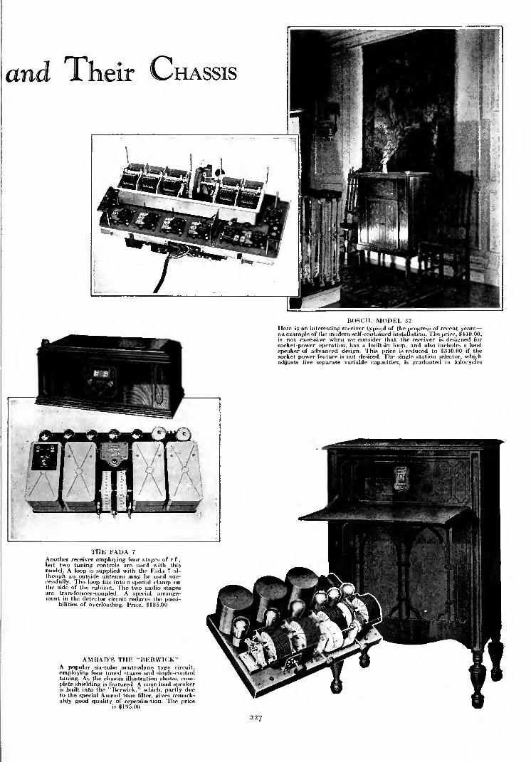
BOSCH, MODEL 57
Here is an interesting receiver typical of the progress of recent yearsan example of the modern self-contained installation. The price, $440.00,is not excessive when we consider that the receiver is designed for
socket-power operation, has a built-in loop, and also includes a loud
speaker of advanced design. This price is reduced to $340.00 if thesocket power feature is not desired. The single station selector, whichadjusts five separate variable capacities, is graduated in kilocycles
THE FADA 7
Another receiver employing four stages of r.f.,
but two tuning controls are used with thismodel. A loop is supplied with the Fada 7 al-
though an outside antenna may be used suc-
cessfully. The loop fits into a special clamp onthe side of the cabinet. The two audio stagesare transformer-coupled. A special arrange-ment in the detector circuit reduces the possi-
bilities of overloading. Price, $185.00
AMRAD'S THE "BERWICK"A popular six-tube neutrodyne type circuit,
employing four tuned stages and single-controltuning. As the chassis illustration shows, com-
plete shielding is featured. A cone loud speakeris built into the "Berwick," which, partly dueto the special Amrad tone filter, gives remark-ably good quality of reproduction. The price
is $195.00
227

How Reliable
Are Short
Waves?
RECENT EXPERIMENTSof the General Electric
Company, of engineersfrom other companies,
and of those interested in private re-
search, have resulted in an explanationof many of the mysteries that have sur-
rounded the short waves. Everyone mar-vels at the ease with which amateurscommunicate with fellow enthusiasts
over great distances with small input
powers. We have done it ourselves
communicated and marveled both and
great is the "kick" thereof. It is
undeniably thrilling to take from one's
lamp socket ob-cycle power of less than
one fifth that required to heat the aver-
age electric iron, and to feed it into a
comparatively simple system of apparatusfrom which it emerges as radio-frequency
energy with which we actually ask a manin South Africa how the weather is
there, all the time sitting quietly in
our den surrounded by unimposing gear.
When it is winter in New York it is
summer in South Africa, when day here,
it is night there, and so on. 1 1 is one of the
marvels of our time that two people in
the security of their homes but separated
by 7000 miles can transfer their thoughts
instantaneously and economically.
Just how good are these short waves?How reliable is communication? Howmany hours of the day, how many daysof the year, can we send messages via
short waves from New York to SouthAfrica?
The results of several investigations point to
the following facts which seem fairly well estab-
lished. Ten meters (30,000 kc.) is probably the
shortest useful wavelength. Below about 20meters (15,000 kc.) the waves prefer to travel in
the daylight, and above that wavelength, nighttime is the best. Below about 45 meters (6660
kc.) curious "skip distances" occur, resulting in
regions beyond which signals are heard but within
which they are inaudible. For example, on 15
meters (20,000 kc.) during daylight, transmission
is not practicable within a distance of 900 miles,
which increases to about 1000 miles at night,
although it is possible to transmit signals for
reception at points more distant than these
figures indicate. At 27 meters (11,000 kc.) the
daytime skip distance has been reported as 1000
miles and 450 miles at night, these distances
being about the same at 33 meters (0.086 kc.).
The General Electric experiments show that
the 32.79-meter wave is no good at all for short
distances. A power output of 500 watts on 65.16meters (4500 kc.) will, however, transmit com-mercial daytime signals up to 100 miles.
Short waves seem necessary for extremely long-
distance communication. During daytime, wavesof the order of 20 meters should be used ; waves
below about 45 meters are not much good for
short-distance work.
Night after night we have heard NAA on 37.5meters pound away at a terrific rate, we have
listened to the Marconi beam stations on 26
rom
-i.
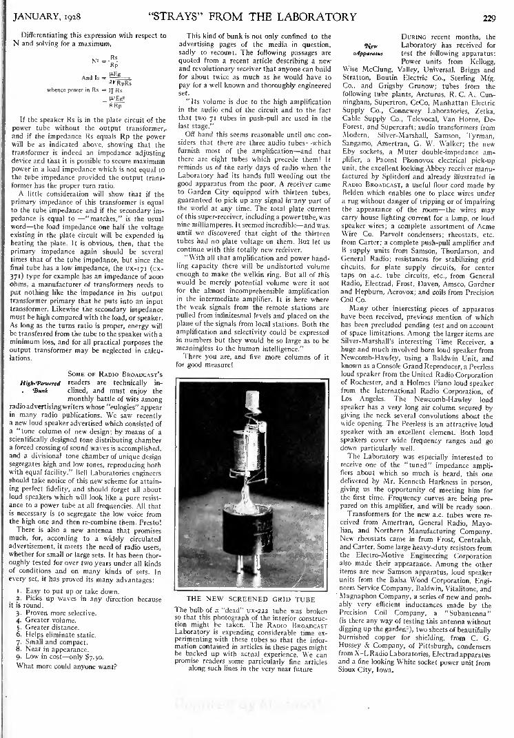
JANUARY, 1928 "STRAYS" FROM THE LABORATORY 229
Differentiating this expression with respect to
N and solving for a maximum,
And Is ;
whence power in Rs =I| Rs
H-Eg'
8Rp
If the speaker Rs is in the plate circuit of the
power tube without the output transformer,,and if the impedance Rs equals Rp the powerwill be as indicated above, showing that the
transformer is indeed an impedance adjustingdevice and that it is possible to secure maximumpower in a load impedance which is not equal to
the tube impedance provided the output trans-
former has the proper turn ratio.
A little consideration will show that if the
primary impedance of this transformer is equalto the tube impedance and if the secondary im-
pedance is equal to "matches," is the usual
word the load impedance one half the voltage
existing in the plate circuit will be expended in
heating the plate. It is obvious, then, that the
primary impedance again should be several
times that of the tube impedance, but since the
final tube has a low impedance, the ux-iyi (cx-
371) type for example has an impedance of 2000
ohms, a manufacturer of transformers needs to
put nothing like the impedance in his outputtransformer primary that he puts into an inputtransformer. Likewise the secondary impedancemust be high compared with the load, or speaker.As long as the turns ratio is proper, energy will
be transferred from the tube to the speaker with aminimum loss, and for all practical purposes the
output transformer may be neglected in calcu-
lations.
SOME OF RADIO BROADCAST'S
High-Towered readers are technically in-
Bimt clined, and must enjoy the
monthly battle of wits amongradio advertising writers whose "eulogies" appearin many radio publications. We saw recentlya new loud speaker advertised which consisted of
a "tone column of new design; by means of a
scientifically designed tone distributing chambera forced crossing of sound waves is accomplished,and a divisional tone chamber of unique designsegregates high and low tones, reproducing bothwith equal facility." Bell Laboratories engineersshould take notice of this new scheme for attain-
ing perfect fidelity, and should forget all aboutloud speakers which will look like a pure resist-
ance to a power tube at all frequencies. All thatis necessary is to segregate the low voice fromthe high one and then re-combine them. Presto!
There is also a new antenna that promisesmuch, for, according to a widely circulated
advertisement, it meets the need of radio users,whether for small or large sets. It has been thor-
oughly tested for over two years under all kindsof conditions and on many kinds of sets. In
every set, it has proved its many advantages:
1. Easy to put up or take down.2. Picks up waves in any direction because
it is round.
3. Proven more selective.
4. Greater volume.
5. Greater distance.6. Helps eliminate static.
7. Small and compact.8. Neat in appearance.9. Low in cost only $7.50.
What more could anyone want?
This kind of bunk is not only confined to the
advertising pages of the media in question,
sadly to recount. The following passages are
quoted from a recent article describing a newand revolutionary receiver that anyone can build
for about twice as much as he would have to
pay for a well known and thoroughly engineeredset.
"Its volume is due to the high amplificationin the audio end of the circuit and to the fact
that two 71 tubes in push-pull are used in the
last stage."
Off hand this seems reasonable until one con-
siders that there are three audio tubes whichfurnish most of the amplification and that
there are eight tubes which precede them! It
reminds us of the early days of radio when the
Laboratory had its hands full weeding out the
good apparatus from the poor. A receiver cameto Garden City equipped with thirteen tubes,
guaranteed to pick up any signal in any part of
the world at any time. The total plate current
of this super-receiver, including a power tube, was
ninemilliamperes. It seemed incredible and was,until we discovered that eight of the thirteen
tubes had no plate voltage on them. But let us
continue with this totally new receiver.
"With all that amplification and power hand-
ling capacity there will be undistorted volume
enough to make the welkin ring. But all of this
would be merely potential volume were it notfor the almost incomprehensible amplificationin the intermediate amplifier. It is here wherethe weak signals from the remote stations are
pulled from infinitesmal levels and placed on the
plane of the signals from local stations. Both the
amplification and selectivity could be expressedin numbers but they would be so large as to be
meaningless to the human intelligence."There you are, and five more columns of it
for good measure!
THE NEW SCREENED GRID TUBEThe bulb of a "dead" ux-222 tube was brokenso that this photograph of the interior construc-tion might be taken. The RADIO BROADCASTLaboratory is expending considerable time ex-
perimenting with these tubes so that the infor-mation contained in articles in these pages mightbe backed up with actual experience. We canpromise readers some particularly fine articles
along such lines in the very near future
DURING recent months, the
^few Laboratory has received for
^Apparatus test the following apparatus:Power units from Kellogg,
Wise McClung, Valley, Universal, Briggs and
Stratton, Boutin Electric Co., Sterling Mfg.Co., and Grigsby Grunow; tubes from the
following tube plants, Arcturus, R. C. A., Cun-ningham, Supertron, CeCo, Manhattan Electric
Supply Co., Connewey Laboratories, Zetka,Cable Supply Co., Televocal, Van Home, De-
Forest, and Supercraft; audio transformers from
Modern, Silver-Marshall, Samson, Tyrman,Sangamo, Amertran, G. W. Walker; the newEby sockets, a Muter double-impedance am-plifier, a Pacent Phonovox electrical pick-upunit, the excellent looking Abbey receiver manu-factured by Splitdorf and already illustrated in
RADIO BROADCAST, a useful floor cord made byBelden which enables one to place wires undera rug without danger of tripping or of impairingthe appearance of the room the wires maycarry house lighting current for a lamp, or loud
speaker wires; a complete assortment of AcmeWire Co. Parvolt condensers; rheostats, etc.
from Carter; a complete push-pull amplifier andB supply units from Samson, Thordarson, andGeneral Radio; resistances for stabilizing grid
circuits, for plate supply circuits, for center
taps on a.c. tube circuits, etc., from General
Radio, Electrad, Frost, Daven, Amsco, Gardnerand Hepburn, Aerovox; and coils from Precision
Coil Co.
Many other interesting pieces of apparatushave been received, previous mention of whichhas been precluded pending test and on accountof space limitations. Among the larger items are
Silver-Marshall's interesting Time Receiver, a
huge and much involved horn loud speaker from
Newcomb-Hawley, using a Baldwin Unit, andknown as a Console Grand Reproducer, a Peerless
loud speaker from the United Radio Corporationof Rochester, and a Holmes Piano loud speakerfrom the International Radio Corporation, of
Los Angeles. The Newcomb-Hawley loud
speaker has a very long air column secured bygiving the neck several convolutions about thewide opening. The Peerless is an attractive loud
speaker with an excellent element. Both loud
speakers cover wide frequency ranges and godown particularly well.
The Laboratory was especially interested to
receive one of the "tuned" impedance ampli-fiers about which so much is heard, this onedelivered by Mr. Kenneth Harkness in person,
giving us the opportunity of meeting him for
the first time. Frequency curves are being pre-pared on this amplifier, and will be ready soon.
Transformers for the new a.c. tubes were re-
ceived from Amertran, General Radio, Mayo-lian, and Northern Manufacturing Company.New rheostats came in from Frost, Centralab,and Carter. Some large heavy-duty resistors fromthe Electro-Motive Engineering Corporationalso made their appearance. Among the otheritems are new Samson apparatus, loud speakerunits from the Balsa Wood Corporation, Engi-neers Service Company, Baldwin, Vitalitone, and
Magnaphon Company, a series of new and prob-ably very efficient inductances made by thePrecision Coil Company, a "Subantenna"(is there any way of testing this antenna without
digging up the garden?), two sheets of beautifullyburnished copper for shielding, from C. G.
Hussey & Company, of Pittsburgh, condensersfrom X-L Radio Laboratories, Electrad apparatusand a fine looking White socket power unit fromSioux City, Iowa.

oncomitants
THE AMPLION "GRAND"A S PLEASING to the eye as to the ear** is this magnificent loud speakingdevice by Amplion. Contrary to what onemight justly suppose upon first glance, the"Grand" does not use a horn inconceivablymunificent in inches, but employs a com-bination cone and sound board. The"Grand" lists at $145.00. It is supplied witha 20-foot cord. The walnut cabinet measures
34" x 33" x 18"
BY PACENT
HERE is a seven teen-inch cone loud speaker
with several interesting fea-tures. Its extreme rugged-ness and responsiveness toweak signals are features.The manufacturer claimsthat this cone has a thirtyper cent, greater frequencycoverage and sensi I i vi t ythan most of the popularmodel cones on the market.
Price, $22.50
Is,
TO THE LEFTA new power cone loud
speaker employing electro-
dynamic principles. Due to its
unique construction, great vol-ume may be handled withoutany possibility of rattling. Anexternal source of direct currentis necessary for operating thisinstrument. Either the storagebattery or the electric lightmains may be employed for this,
depending upon which type ofloud speaker is used. If the
storage battery is employed, thecurrent drain will not exceedthat usually drawn by a 171
type tube. The price of the**Aristocrat" is $85.00 for stor-
age battery operation or $90.00for 110-voltd. c. operation
THE MAGNAVOX "ARISTOCRAT"
DESIGNED FOR HEAVY-DUTY WORKrpHERE are four voltage taps on this new B supply device-1 by National, three of which are adjustable. The detector
voltage is from 22 to 45; the r.f. voltage, from 50-75; and thea.f. voltage from 90-135. The power-tube voltage tap delivers
180 volts. Price, with cord, switch, and plug, $40.00. Rectifier
tube, $5.00
230

of (rood Quality
EXPONENTIAL HORNS
A GOOD exponen tial horn is capableof very excellent results so far as qual-
ity reproduction is concerned, and is excep-tionally efficient. The Temple Console U>
the right employs a 75-inch exponentialair column, and is priced at $65.00. TheTemple Drum below also has an exponen-tial air column and comes in two models,
using 54-inch and 75-inch air columns,priced at $29.00 and $18.50 respectively
.
A NKW SOCKET-POWER DEVICE
TpOGETHER with a relay which automatically switches theA house electric light supply to the B device illustrated, orto a trickle charger, depending upon whether the set is in useor not. These devices are by Slromberg-Carlson, of Kochester,
and retail at: H device. $63.00 (with tube); relay, $11.00
FOR THE PHONO-RADIO COMBINATION
THE Platter Cabinet Company, North Vernon,Indiana, is responsible for this attractive cabinet
of walnut plyw<>od, in which space is provided fora complete radio installation and a phonograph.The price of the cabinet is $72.00. The same manu-facturer will supply turntable, motor (electricalor mechanical), radio receiver, electrical pick-updevice, and joud speakers of many patterns to fit
into the cabinet, if desired
231

THE GREBE "SYNCHROPHASE" SEVENThe circuit diagram of this receiver is shown on the next page
How the "Synehr
rE REQUIRE a seven-tube receiver
with single tuning control to be sold
at a retail price of $ 13 5.00. Produce it."
Such, in effect, might have been the wordingof a memorandum from the board of directors of
A. H. Grebe to the engineers responsible for the
design of the"Synchrophase
"Seven. Thereupon,
a tedious process of laboratory and mathematical
experiment sets in, for the "cut and try"methods of "mediaeval" radio days are for-
gotten, since present broadcasting conditions
would make such procedure impracticable.
Being familiar with the congestion amongstations, the transmitting characteristics of the
broadcasting stations, and the power used by the
stations, the radio engineering department wasable to select the number of tubes to be used as
radio-frequency amplifiers, decide upon the
detector system, and arrive at a decision con-
cerning the number of stages of audio-frequency
amplification necessary to produce a satisfactory
receiver output signal. They were aware of the
operating channels used by broadcasting stations
in various localities, hence they could judge if
their tuning system would be capable of separat-
ing the stations and of providing radio receptionwithout a background of interference from other
stations.
This was, however, not all a matter of guesswork. Such perfectly engineered radio receivers
are first produced on paper, with the aid of
mathematics and the "slip stick" (a nick-namefor the slide rule). The amount of time put into
the design of radio receivers of modern times is
almost inconceivable when compared to that of
six or seven years ago.After due deliberation, the decision of the
Grebe engineers was to employ four stages of
tuned radio-frequency amplification, a non-
regenerative detector, and two stages of trans-
former-coupled audio-frequency amplification.The question then arose relative to the design
By John F. Rider
of the radio-frequency system. Should it be
shielded or unshielded? Development carried
out prior to this time resulted in the birth of
a new type of fieldless inductance an induct-
ance which could be used in a multi-stage tuned
radio-frequency receiver without fear of coil
interaction. This coil, known as the "binocular"
inductance, was the brain child of P. D. Lowell,
and is the evolutionary development of the
toroidal winding. Since this coil is fieldless, inter-
stage shielding was unnecessary; two, three, or
four stages of unshielded tuned radio-frequency
amplification may, therefore, be used without
worrying about excessive regeneration. Elimi-
nate the coil fields and shielding is unnecessary,since coil interaction will not take place. Theelimination of shielding means economy without
any sacrifice.
The function of shielding is also to precludedirect coil pickup, but since the fieldless coil will
not pick up any energy, shielding is unnecessaryon this account. The binocular coil, therefore,
solved several problems in the design of the
"Synchrophase" Seven. The coil itself consists
of two solenoidal windings mounted closely
together with their axes parallel and with the
two windings connected in such a manner that
their electromagnetic fields are opposing each
other. This means that, if one coil starts to ra-
diate a magnetic field, the other coil simultane-
ously radiates a magnetic field of equal intensitybut of opposite phase or direction, and the twofields combine and counterbalance each other.
The result of the- combined fields is zero.
Hence, no reaction between the tuned trans-
formers is evident.
The same phenomenon applies to the pickupof waves by the transformers. A voltage intro-
duced in one coil is reacted upon by the voltageintroduced in the other coil by that passingwave. The two induced voltages react upon each
other and the resulting induced voltage is zero.
232
Hence pickup of energy is not apparent. Thefact that these coils are fieldless permits of a
layout different from that possible when the
coils used have strong fields. Interaction of fields
is the greatest objection to the single-layer sole-
noid. It is a very efficient winding out possesses a
very strong field, and total shielding is impera-tive in a receiver employing a number of single-
layer solenoid radio-frequency transformers.
The next problem was the actual design of the
binocular inductances. The mere selection of a
form of winding does not complete the design
problems of the tuned radio-frequency trans-
formers. Solid wire is conventional for the aver-
age tuned radio-frequency transformer. Is it
best for these coils? Does the form factor of the
average coil apply to this type of winding?Can some other wire be used to greater advan-
tage? Here is room for research and experiment.The first binocular coils were wound with
solid wire. Further experiments and calculations
by the engineering department proved conclu-
sively that "litz" wire improved the inductance-
resistance ratio to a large extent and as far as
practical results were concerned, coils woundwith "litz" wire could be made to have a moreuniform amplification curve over the broadcast
frequency spectrum, in addition to improvingthe selectivity of the tuned circuit. Here againwe find a deviation from the conventional path."Litz" wire has frequently been frowned uponas unsuited for high-frequency work. The de-
signers of the "Synchrophase" have overcomethe difficulties and are utilizing "litz" to good
advantage.The occasion next arose for the development
of an original system to overcome a frequently
occurring fault with conventional tuned radio-
frequency amplifiers. It is of paramount im-
portance that the frequency response curve of
the radio-frequency system be substantially flat.
Furthermore it is desirable that the effects of the
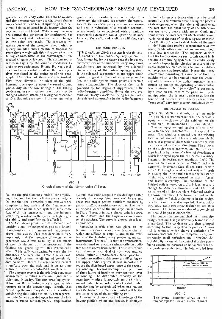
JANUARY, 1928 HOW THE "SYNCHROPHASE" SEVEN WAS DEVELOPED 233
grid-filament capacity within the tube be so nulli-
fied that the purchaser can use whatever tubes he
may choose without fear of upsetting the tuned
circuit balance obtained in the factory when the
receiver was first tested. With many receivers
the neutralizing condenser (or condensers) has
to be readjusted whenever any changesin the tubes are made. The frequency re-
sponse curve of the average tuned radio-fre-
quency amplifier shows maximum response on
some short wavelength (high frequency) with a
falling characteristic as the wavelength is in-
creased (frequency lowered). The system repre-
sented in Fig. i by the variable condenser dand the two resistances, R\ and Rz, was devel-
oped and incorporated to attain the two objec-
tives mentioned at the beginning of this para-
graph. The action of these units is twofold.
First, they eliminate the effect of the grid-
filament tube capacity upon the tuned circuit,
particularly on the low settings of the tuning
condensers, in such manner that tubes may be
changed without affecting the original resonance
setting. Second, they control the voltage being
give sufficient sensitivity and selectivity. Fur-
thermore, the sideband suppression characteris-
tics of the radio-frequency system are knownand the introduction of a variable constant,
which would be encountered with a variable
regenerative detector, would upset the balance
between the radio and audio amplifiying sys-
tems.
THE AUDIO CHANNEL
THEaudio amplifying system is closely asso-
ciated with the radio-frequency system; in
fact, it must be, for the reason that the frequencycharacteristics of the audio-frequency amplifyingtransformers are governed by the sideband
characteristics of the radio-frequency system.If the sideband suppression of the upper audio
register is great in the radio-frequency ampli-fier, the audio system must possess a certain
rising characteristic. The slope of the rise is
governed by the degree of suppression in the
radio-frequency amplifier. Hence the two sys-tems are closely associated. Being familiar with
the sideband suppression in the radio-frequency
~Gnd.
FIG. 1
Circuit diagram of the "Synchrophase" Seven
fed into the grid-filament circuit of the amplify-
ing tube, so that the radio-frequency voltagefed into the tube is practically uniform over the
complete tuning scale and the frequency re-
sponse curve of the tuned system is sufficiently
flat. With this arrangement, and the inherent
lack of regeneration in the system, a high degreeof stability and amplification is afforded.
The four stages provide ample selectivity and
sensitivity and are designed to possess sideband
characteristics with minimized suppressionabove 1000 cycles. This consideration is very
important, and the presence of excessive re-
generation would tend to nullify all the effects
of scientific design. But the properties of the
fieldless coil guard against this deterimental
effect. With sufficient spacing between the in-
ductances, the very small amount of external
field, which cannot be eliminated completely,does no harm. Hence the regeneration presentis uniform over the scale and is at no time
sufficient to cause uncontrollable oscillation.
The detector system is the grid leak-condenser
arrangement, affording maximum signal sensi-
tivity and intensity. The compensating systemutilized in the radio-frequency stages, is also
resorted to in the detector input circuit, thus
permitting the use of any detector tube without
unbalancing the tuning system. A non-regenera-tive detector was decided upon because the four
stages of tuned radio-frequency amplification
system, two audio stages are decided upon after
a study of the amplifying powers of the system;these two stages possess sufficient magnifying
power to afford a satisfactory output. The over-
all response curve of the audio system is shownin Fig. 2. The gain in transmission units is shownon the ordinate and the frequencies are shownon the abscissa. The curve is plotted on a loga-
rithmic scale.
Particular consideration was given to the
feminine speaking voice, the frequencies of
which are difficult to amplify, and to the over-
tones of the high-frequency producing musical
instruments. The result is that the transformers
were designed to function satisfactorily on audio
frequencies above 8000 cycles. This is easier said
than done. A great deal of work was entailed
before suitable transformers were produced.In order to realize satisfactory amplification on
the upper audio register it was important to
reduce the distributed capacitance of the second-
ary winding. This was accomplished by the use
of three layers of insulation between each layer
of winding. The distributed capacity of the
secondary winding is approximately 18 micro-
microfarads. The importance of a low distributed
capacity can be appreciated when one realizes
that the higher it is, the more limited will be the
frequency range of the amplifying unit.
An example of vision, and a knowledge of the
buying public's whims and fancies, is displayed
in the inclusion of a device which permits tonal
flexibility. The problem arose during the processof development when the sales staff mentioned
the fact that the aural fancy of the listener-in
was apt to vary over a wide range. Could not
some device be incorporated which would permitvariation of the tone of received speech or music,so as to satisfy the individual tastes of the mul-titude? Some fans prefer a preponderance of low
tones, while others are not so anxious aboutthese low frequencies. The engineers decided
that the best location for such a unit would be in
the audio amplifying system, but a continuouslyvariable change in the physical structure of the
audio-frequency transformers to produce differ-
ent response was impractical. Hence the "tonecolor" unit, consisting of a number of fixed ca-
pacities which can be shunted across the second-
ary of the second-stage audio-frequency trans-
former to change its operating characteristic,
was originated. The "tone color" is controlled
by a knob on the front of the panel and, by its
manipulation, the listener is able to adjust the
tone to suit his own taste. The capacities in the
"tone color" vary from 0.00008 mfd. downwards.
THE PROCESS OF TESTING
CNG1NEERING and originality has made-<
possible the manufacture of all the necessary
equipment, exclusive of the cabinets, in the
Grebe plant, at Richmond Hill, Long Island.
The manufacture and testing of the tuned
radio-frequency inductances is of especial in-
terest. The winding is spaced yet the windingform is not grooved. This is made possible bymeans of a grooved slider which carries the wire
as it is wound on the winding form. The grooveson the slider space the wire, and the turns are
kept in place by means of a layer of clear lacquerwhich is sprayed upon the coil before assembly.
Ingenuity in testing now manifests itself. Thewire, as mentioned before, is "litz," and it is
extremely important that all the turns remainintact. If a single strand is broken it will result
in a steep rise in the radio-frequency resistance
of the wire, with consequent increase in losses,
and lower selectivity. The condition of the
finished coils is tested on a d.c. bridge, accurate
enough to show one broken strand. The total
resistance of all the strands is balanced againsta known resistance. One broken strand in the
"litz" cable will deflect the meter in the bridge,in which case the coil is rejected. The satisfac-
tory coils' radio-frequency resistances are then
measured. The inductance value of a completedcoil should be 310 microhenries.
The condensers are matched on a capacity
bridge, each one being individually tested againsta standard. The condensers are then groupedaccording to their respective capacities. A con-
trol is arranged which shows a variation of 7micro-microfarads for the complete scale, and
extremely small variations are, therefore, de-
tectable. By means of this control it is also possi-ble to determine increased effective resistance of
the condenser under test. The bridge is fed from

234 RADIO BROADCAST JANUARY, 1928
a looo-cycle source and the output of the bridgeis connected to a single-stage audio amplifier,
thus increasing the sensitivity of the system.The operator uses the headphone method of
adjusting for capacitance by finding the mini-
mum sound intensity. When the sound is min-
imum the capacity of the unknown is exactly
that of the standard. A condenser with highlosses does not permit of complete silence in the
phones, and is rejected.
The audio-frequency transformers are also
tested in an interesting manner. It is highly im-
portant to know the response of the transformers
to be. placed in the receiver, but it would be a
tedious procedure to plot a response curve for
each individual unit, hence each transformer is
compared with a standard on certain frequencies.A tube oscillator, generating a 5OO-cycle note
and a 6ooo-cycle note, is connected to a standard
amplifier. The output of this amplifier is con-
nected to the transformer to be tested, and the
output of the transformer under test is connected
to a vacuum-tube voltmeter, the output circuit
meter of which gives visual deflections indicative
of the response of the transformer under test.
The circuit is so arranged that, by means of an
anti-capacity switch, the transformer under test
can be replaced by the standard and the deflec-
tions compared. By means of a switch, the oscilla-
tor can be adjusted to generate either the 500-or the 6ooo-cycle signal. This signal is free of
harmonics and is constant at all times. The de-
flections with the standard transformer are
therefore constant.
The complete receiver undergoes several tests,
and the method of testing is also original andnovel. A buzzer-modulated master oscillator,
tuned to 200, 400, and 530 meters (i 500, 750, and
566 kc.) feeds a master antenna. The buzzer
modulation is accomplished by breaking the
plate voltage supply with the interruptions of the
buzzer. The operator testing the receiver (several
operators are testing at one time) has his ownantenna of standard inductance and capacitancevalue. He first adjusts the receiver at 200 meters
by tuning it to resonance with the 2oo-meter
oscillator signal. The receiver output is then
noted by means of a tube voltmeter connected
to the output circuit of the receiver. After the
receiver is adjusted on 200 meters, adjustmentsare made on 400 and 530 meters, and the second
harmonic of 530, which is 265 meters (i 130 kc.).
In this way each receiver is tested on four wave-
THE GREBE CONE LOUD SPEAKER
lengths. This is indeed a comprehensive test, for
it will bring to light any defects in design uponany of the wavelengths within the range em-
ployed for broadcasting purposes. If the tube
voltmeter does not show standard output on all
four waves, the receiver is rejected for a re-
examination.
The problem of conductive coupling in the
receiver to adjacent leads was overcome by the
use of the chassis as the negative filament lead,
thus eliminating numerous long leads. The fila-
ment wiring in the receiver consists of only the
positive polarity wires. The negative lead is
formed by the chassis. The condensers are all
grounded upon the chassis.
The mechanical alignment is facilitated bypunching the complete chassis in one piece. It is
made out of aluminum and stamped out on a
6o-ton press. The chassis, after the stamping,carries all the mounting holes and brackets, thus
assuring correct alignment. The receiver, from
start to finish, is carried from one operation to
another by means of a conveyer system approxi-
mately moo feet in length. This conveyer con-
sists of a belt or a roller as the occasion demands,
AN INTERIOR VIEW OF THE "SYNCHROPHASE" SEVEN
and the partially assembled receiver moves from
one operation to another until it finally reaches
the final department.
THE GREBE CONE
T~HE electrical development of the Grebe loud'
speaker is also of interest, particularly be-
cause this field of endeavor requires highlytrained engineering. The development of a loud-
speaker does not consist of the mere selection
of steel, iron, wire, and a paper cone. Let us con-
sider for a moment an important consideration
which the fan generally passes over very lightly.
T his is the angle of the apex of the cone, and the
size of the cone. The information relative to the
size of the cone will doubtless be of interest to
constructively inclined radio fans. According to
the engineer in charge of cone construction, their
experiments showed that a 20" cone was the best
compromise and that increases above this diam-eter did not justify the additional space required.
Experiments showed that very little is gained byusing a cone of larger diameter. Reduction in
size, however, showed a material loss.
As to the angle of the apex, 20 degrees is also
the best compromise for efficiency and quality.The greater the angle, the greater the efficiencybut the poorer the quality of reproduction. The
2o-degree angle was considered the best for
quality and efficiency. Many articles publishedin this and other periodicals have stressed the
importance of a large value of inductance for
loud speaker windings in order to produce satis-
factory response on the low frequencies. Withthis in mind, a value of 1.7 henries was selected
as the loud speaker coil inductance. The shapeof the armature is also an important considera-
tion, and by using an armature that is wide and
short, the lowest moment of inertia is obtained.
The selection of the material for the armaturealso requires care and silicon steel was choseninstead of Swedish iron, because the losses of
silicon steel are less on the higher audio register.
The difference between Swedish steel, iron, andsilicon steel is not appreciable on the lower audio
register but it approaches an appreciable value
on the higher audio frequencies.The elimination of harmonics in the average
loud speaker is a paramount item because their
presence will not pecmit true reproduction. Toattain this result it is necessary to minimize
magnetic saturation.
The testing of the loud speaker is carried out
by first subjecting it to a series of audio fre-
quencies obtained from a beat note oscillator.
This beat note oscillator consists of two radio-
frequency oscillators adjusted in a manner which
permits the generation of a beat note; this note
is passed through several stages of audio-
frequency amplification and then into the loud
speaker. One of the radio-frequency oscillators,
is variable in tuning and the frequency of the
beat note is variable between 50 and, approxi-
mately, 20,000 cycles. This test will bring to
light any defects in the loud speaker mechanismwhich would result in a rasping sound or a rattle
when it is placed into operation. Another test
consists of the reproduction of an organ record
played upon a talking machine and fed into the
loud speaker by means of an electric pick-upand amplifier combination. The organ selection
has a wealth of low notes, and these are particu-
larly desired for testing purposes, since the
amplitude of these low frequencies is high. This
test will bring to light any defects in the place-ment of the armature. Another test consists of
the application of the plate current of a 171 tube
through the windings of the loud speaker,first in one direction and then in the other,
to test for magnetic saturation when it is in
operation.

AS IHhRY TAUI DkKHfck
TECHNICALproblems presented in this
section in the past have consisted of
numerical problems requiring more or
less lengthy solutions, so that only one question
could be allowed to an issue. We shall vary these
occasionally by a series of questions requiring
only brief answers, like those below. The sub-
jects, while not strictly confined to the design
and operation of broadcast transmitters and as-
sociated apparatus, will have some connection
with those considerations of quality in repro-
duction which are of most interest to the profes-
sional broadcast technician.
QUESTION i. Why does sharp tuning tend to
drop out the high audio frequencies associated
with a carrier?
Answer. The audio energy of speech or music
exists in the side bands accompanying the car-
rier in question. If, for example, the carrier is
of the order of 600 kilocycles, a frequency within
the broadcast band, and the audio note being
transmitted is 5 kilocycles, the side bands will
have a frequency of 595 and 605 kilocycles. Asharply tuned circuit resonant to 600 kilocycles
will include perhaps one kilocycle on either side,
and will discriminate to a greater and greater
degree against the higher audio frequencies,
which lie further out from the central or carrier
frequency. Hence the 595- and 6o5-kilocycle
currents, in the present example, may be lost
altogether, and with them the ^-kilocycle audio
note which they would yield on demodulation.
By this mechanism, called "side band cutting,"
the higher musical frequencies are likely to be
lost.
QUESTION 2. Why does slight detuning of a
sharply resonant circuit, with reference to the
carrier frequency, tend to reinforce the higher
notes contained in the modulation?
Answer. See Fig. 4, which has reference to the
same example used to illustrate the answer to
Question I. Now, however, the circuit has been
tuned so that the peak of the resonance curve
occurs at 602.5 kilocycles instead of at the carrier
frequency of 600.0 kilocycles. As a result, the
peak of receptivity, after demodulation, has
been shifted from currents of frequencies in the
neighborhood of zero cycles to currents in the
neighborhood of 2500 cycles per second. If, ow-
ing to the steepness of the resonance curve, the
cut-off characteristic of the circuit becomes seri-
ous one kilocycle to either side of the peak, as
assumed in the answer to Question i above, with
the peak set at 602.5 kilocycles the audio fre-
quencies up to 3.5 kilocycles are nevertheless in-
cluded in the received band. It will be seen that
through this mechanism a sharply tuned radio
frequency circuit may be used to some degree
as an equalizing or frequency correcting device
in reception. This observation may be checked
in practice. A similar phenomenon is found in
some super-heterodyne receivers.
QUESTION 3. What change in loudness is nor-
mally noticeable by the human ear?
Answer. A change of 3 TU is usually observed
in speech or music even by listeners who are not
expecting it. This corresponds to a change in
energy of 2:1. A practiced listener looking for a
change may detect differences of tha order of i
TU in a sustained note, without much difficulty.
This is equivalent to an energy change of about
25 per cent.
QUESTION 4. What size steps, in TU, would
you allow in a smooth gain control?
Answer. Since, according to the answer to
Question 3 above, a change of 3 TU is notice-
able, the maximum allowable step in a smooth
gain control is 2 TU.
QUESTION 5. What error do non-technical
observers invariably make in estimating rela-
tive loudness of sounds?
Answer. They underestimate radically. As is
well known, the human ear follows a logarith-
mic response characteristic, which is as much as
to say that a large increase or decrease in the
stimulating energy results in a slight changein the loudness subjectively perceived. Or,
more definitely, multiplying the energy by a
fixed ratio results only in adding to the loudness
an increment proportional to the logarithm of
the energy ratio. This is expressed mathemati-
cally in the formula for the telephonic trans-
mission unit, which is a measure of subjective
loudness:TU = 10 log Pi/P2
where PI and P2 are the powers correspondingto the two telephone currents under comparison.Non-technical listeners, being unaware that
hearing is a logarithmic process, usually apply to
sounds the standards of measurement and esti-
mating to which they are accustomed in dealing
with distances, for example. A broadcast listener,
comparing reception from two stations, one of
which is a stage of audio amplification above the
other, will say that the first station is "fifty per
cent, louder," or "one hundred per cent, louder."
Actually one a. f. stage may correspond to 20
TU, or a sound energy ratio of 100. In other
words, a non-technical listener is apt to speak of
an energy ratio of the order of 2:1 where the
actual figure is of the order of 100:1.
Commercial Technical Publications
ALONGcatalogs and technical publica-
tions received we must mention the
September, 1927 issue of the General
Radio Experimenter, a four-page paper sent out
monthly to concerns and individuals on the mail-
ing list of the General Radio Company of Cam-
bridge, Massachusetts. [This publication maybe secured by our readers by filling out the"Manufacturers' Booklet" coupon appearing
in the advertising section in this and other issues.
Booklet number 74. Editor] Thi firm, as is
well known, specializes in communication lab-
oratory and measuring apparatus, such as
standards of inductance, resistance, and capa-
citance, oscillators, oscillographs, audibility
meters, bridges, artificial telephone lines, etc.
Its engineers have played no small part in re-
ducing radio designing to a respectably exact
235
science. The September, 1927 issue of the Experi-menter is of special interest to broadcasters in
that it contains an article on"Design and Use
of Attenuation Networks," by Horatio W. Lam-son. The subject was discussed, it may be re-
membered, in this department for September,
1927 (Pages 293-294). Mr. Lamson's papercovers the same ground, in part, with the addi-
tion of a number of formulae and a detailed
description of the General Radio Company'svariable attenuation networks. Given, as in Fig.
i, a source of impedance Z and an absorbingcircuit or "sink" of the same impedance, joined
by an H-network as shown, with currents I
and I leaving the source and entering the sink,
respectively, for a definite number of transmis-
sion units of attenuation N we may calculate
the arms X and Y from
Z k i
X = -( )
2 k + i
k
where k
or, in TUk = 10 i/ = Antilog /
(0
(2)
(3)
(4)
If, as shown in Fig. 2, we make all five branches
of the H-network adjustable by steps, movingfive switch arms in unison to the proper switch
points through a single control, the character-
istic impedance Z of the network may be main-
tained constant to match the impedances to
either side, while the attenuation is varied in
steps. This is the principle of the Type 239 Vari-
able Attenuation Network supplied by the Gen-
eral Radio Company. The box is equipped with
two multiple switches. In the size which af-
fords a total attenuation of 55 TU, one decade
is calibrated in steps of 5 TU, and the other in
steps of 0.5 TU. Another size goes up to a total
of 22 TU, and in this case the steps are 2TUand 0.2 TU. Characteristic impedances of 600
and 6000 ohms are carried in stock or built to
order. Some types are provided with a center
tap for the Y-branch, where a ground may be
applied.A somewhat older type of variable pad sup-
plied by the same manufacturer is adjusted bythe addition or subtraction of fixed sections,
which are cut in or out by means of four-pole
double-throw switches, as shown in Fig. 3. This
is known as the Type 249. The manipulationof this form is necessarily somewhat less con-
venient, but in many cases it serves the same
purpose and the cost is about half of the rotary
switch form. There are eight-section boxes af-
fording a total attenuation of 1 10 TU in steps of
i TU, and six-section boxes with a total of 63
(>-r\^^WAVVWrWYAS rWWWWVWrWrMAr O
HMrWnAMr'WWVW] i
5J 4 3* 2J li 0*Output Input
FIG.2

236 RADIO BROADCAST JANUARY, 1928
m n
Input Output
TU in the same steps. The same characteristic
impedances, 600 and 6000 ohms, are available.
As explained in the September, 1927, RADIO
BROADCAST discussion, the simpler T-networks
may be used in place of the H-type where a
balanced circuit is not essential. The General
Radio Company also supplies the sectional net-
works in the T-connection, at a somewhat lower
price, inasmuch as the number of coil-taps and
switch-arms required is less.
The Portrait of the Author
MR.FRANKLYN F. STRATFORD, who
embellishes these articles with clever
pictures, sometimes sketches my like-
ness for the customers, so that they may not
shoot the wrong man when they take offense
at my sooth-sayings. In so doing Mr. Stratford
has perpetrated a libel on me. I ask that in-
terested readers turn to the illustration in the,
November, 1927 issue, over the quotation, "Let
the ghost call at my office." The picture includes
the ghost, myself, and part of the office. About
the ghost 1 say nothing; Mr. Stratford's idea of
a ghost is no doubt as good as anyone's. And myown likeness is not bad. It is true that my nose
is depicted as about the size of Cyrano de Ber-
gerac's, and not as well-shaped, but so Godmade me. My head has a contour not unlike
that of a truncated cone, in Mr. Stratford's
sketch, but such geometrical outlines are not
lacking in esthetic value, and it would be worst
if the cone were upside down. What I object to
is the office furniture, and particularly the desk.
The desk depicted seems about four feet wide.
I wish the world to know that my office boy sits
at such a desk. My own desk was made to order
in Circassian walnut, and cost $3000. The top is
a solid piece of Florentine marble, 150 squarefeet in area. Nymphs and satyrs are painted onthe sides. When next Mr. Stratford draws mydesk let him take an extra column and do justice
to his subject.
Linguistic Observation
THEvilest French and German I have ever
heard in the sense of execrable accent,
not of content, be it said is on radio
broad -ast programs, and I refer to many large
stations as well as small ones, if you please. Theradio announcers, with a trifling number of ex-
ceptions, pronounce foreign languages like so
many high school freshmen. The better vaude-
ville circuits are vastly superior in this detail.
When a girl like Kitty Doner spills some French
before the assembled intelligentsia at the NewYork Keith's 8ist Street, it is Parisian French
as you might hear it on the boulevards. But the
announcers drive any half-way educated listener
to thoughts of homicide whenever they have oc-
casion to pronounce a simple phrase like DanseRusse or Wiener Blut. What ails the announcers
and their bosses? Don't they know any better?
Then let them go back to school. Or don't theycare? Then let them seek some business in which
they don't have to appear before the public.
Memoirs of a Radio Engineer: XXI
INSTEAD
of going forward a few moremonths in the recital of these memories,at this point I wish to regress briefly in
order to include an incident which was omitted
in its proper place. It returns to my recollection
when I hear of some broadcast listener endinghis mortal existence by throwing a length of
antenna wire across a high tension line, or
through a fall from a roof. Such fatalities are
too infrequent to deserve mention, perhaps, in
a country which takes no account of some
100,000 deaths in four or five years throughautomobile accidents, but the victims are just
as dead, although not killed in a popular man-ner. I might have joined their number, thus
600 602.5 605
tREQUENCYKilocycles
FIG. 4
swelling the total slightly, but for luck. The time
was about 1914, when I was feeding a crystal
receiving set from a one-wire antenna about
four hundred feet long. So long was it, in fact,
that it crossed a city street. After some monthsof fine reception, during which I was able to
boast to the other amateurs about the great
distances from the phones at which signals
might be heard at my house, the antenna yielded
to the elements one night, and in the morning it
was down. On the street which it crossed there
was an electric power line, the cross arms carry-
ing six or nine heavy rubber covered wires.
My copper strand now lay across these conduc-
tors. I went to the house at the end of the block
and looked up at the transmission line. It did not
appear dangerous, and I decided that it must be
a i lo-volt circuit, and that nothing much could
happen. However, I decided to be very prudent,so 1 went below for a bamboo trout rod, made a
cast for my antenna wire, hooked it, and lifted
it off the transmission line. It fell back, however,and I grasped it impatiently in my bare hands
and swung it clear. Nothing happened. Whatcould happen even if a boy radio operator got
his antenna tangled up with a I lo-volt line
covered with an eighth of an inch of rubber?
But the other day I passed along that block,
and, thirteen years older, looked up at the trans-
mission line, which was unchanged in equipmentand fittings, as far as I could judge. It is not a
no-volt line, and probably never was one. It
may be carrying its load at a tension of 2200
volts, or perhaps 4400. Either would have been
enough. Some people have luck. The insulation
on the wires was not frayed.
The Radioman's "Britannica"
DRAKE'S RADIO CYCLOPEDIA. By Harold P.
Manly. Published by Frederick J. Drake and
Company, Chicago. Price $6.00. Pages, about
800. Illustrations, 950.
MR.MANLY'S "Cyclopedia" is a com-
prehensive compilation of all the con-
ceivable information which a set builder
and designer needs for ready reference. Thereviewer could not, of course, read the entire
work in detail because that would require several
weeks, but many pages were critically examined.
The first impression gained is the completenesswith which the author covers his subject.
As an example of the wealth of detail on a
'particular subject, under the heading of"Re-
ceiver, Audio Amplifier for," constructor's cir-
cuit diagrams, showing the arrangement of parts,
wiring, outstanding performance qualities, and
specifications of components, are given for fifteen
types of audio amplifier systems, including three-
stage choke-coupled, three-stage transformer-
coupled, one transformer and two choke-coupled,
three-stage double impedance, one transformer
and one push-pull stage, two push-pull stages,
three resistance-coupled stages, one transformer
and three resistance stages with output choke,
two transformer stages with output transformer,
two transformer stages with parallel outputtubes, two transformer stages with potentiometercontrol.
In the matter of receiving circuits, the follow-
ing types are described: Browning-Drake,
crystal, four-circuit, long-wave, loop, "N" cir-
cuit, neutrodyne, one-tube, regenerative, Rice,
Roberts, short-wave, single-circuit, single-control,
super-heterodyne (13 pages), super-regenerative,and tuned radio-frequency.A table, "Coil Design, Advantages and Disad-
vantages of Types of Coils," is an example of the
practical kind of information collected in a
manner suited to easy reference. This table lists
various elements of coil design, such as type of
winding, shape of winding, proportion of wind-
ing, wire insulation, wire size, material of windingform, design of winding form, fastening of wind-
ing, material of supports and connections to
winding, and gives under each of these headingsthree to six different practices which may be
followed. For example, under "Material of
Form," paraffined paper or cardboard, fibre and
"mud" dielectrics, dry paraffined wood, hard
rubber, phenol, bakelite, and glass are listed.
Under each of these design possibilities, the
characteristics of each type is given in the
simplest terms, "poor, fair, good, and best,"
for the following factors: Durability, most in-
ductance, least resistance, little distributed
capacity in small field. Thus, "type of winding,
(i) cylindrical, single wire, close wound," is de-
clared the "best" from the standpoint of durabil-
ity, most inductance, and least resistance, but
"poor" from the standpoint of less distributed
capacity and small field. Honeycombs, on the
other hand, are good from the standpoint of
durability, inductance, less distributed capacity,
and small field, but only fair from the resistance
standpoint. By the aid of the table, the designer
may select the type of winding form which best
suits his purpose.In addition to covering constructional informa-
tion, due space is given to practical operation,
general theory, and design. Power supply for A,
B, and C potential, design of receivers with alter-
nating-current supply for filament lighting,
single-control, shielding, are some of the subjects
fully treated, indicating the volume to be up to
the minute.
One mysterious feature of the whole work is
that hardly a single line of credit is given for
sources of information and assistance. Not a
page in this book is numbered. The reviewer does
not believe, however, that a more satisfactory
addition to the experimenter's library, in anyone volume, can be made.
E. H. F.

RADIO BROADCAST ADVERTISER 237
cNowAC Electric Radio
To owners of a
"B" eliminator:
Balkite"A" is like Balkite
"AB" but for the "A"circuit only. It enables youto make an electric instal-
lationat very low cost. $35.
Balkite BThe accepted, tried and
proved light socket "B"supply. One ofthe longestlived devices in radio.Three models, #22.50,
5, $42.50.
Balkite ChargersStandard for "A" batter-
ies. Noiseless. Can be usedduring reception. Highrate or trickle.Three mod-els, $17.50, $9.50, $7.50.
There are special models for 25-
4Qcycle current at slightly high-er prices. Prices are higher West
of the Rockies and in Canada.
Withoutthe uncertainty ofuntried apparatus
And without anysacrifice in quality
of receptionOf course you want an AC electric re-
ceiver. For its convenience. Now youcan have it, without the uncertainty of
untried apparatus and without sacri-
ficing quality of reception.
Simply by adding Balkite Glectric
"AB" to your present radio set. Balkite
lectric "AB" replacesboth "A" and "B" bat-
teries and supplies radio
power from the lightsocket. It contains no
battery in any form. It
operates only during re-
ception. It makes anyreceiver an electric set.
This method makes
possible the use in elec-
tric reception ofstandard
sets and stand-
ardtype tubes.
Both are tried
and proved,and give by far
Chicago Civic Operaon the airThursdayEven-
ings, 10 o'clock Eastern
time. Over stations WJZ,WBZA.WBZ, KDKA,KYW,WGN, WMAQ, WBAL,WHAM,WJR,WLW,WENR.10:30 Easterntime: WEBH,KSD, WOC, WOW, WCCO,WHO.WDAF.BALKITE HOUR
Balki
the clearest and truest reproduction.With this method there is no waitingfor tubes to warm up. No difficulty in
controlling volume. No noise. No AChum. No crackling or fading of power.Instead the same high standard of re-
ception to which you are accustomed.
In this method there is nothing ex-
perimental, nothing untried. It consists
of two of the most dependable productsin radio a standard set and Balkite.
And ifyou should already own a radio
set, the cost of equipping it with Bal-
kite is only a fraction of the cost of a
new receiver.
By all means go to AC reception. Its
convenience is the greatest improve-ment in radio. But be as
critical ofanAC receiver
as you would of anyother. That your ACreceiver be a standard set
equipped with Balkite
electric "AB." Then it
will be as clear and faith-
ful in reproduction as
any receiveryou can buy.
Two models, #64.50and #74.50. Ask your
dealer. Fan-steel Products
Co . , Inc. ,
North Chi-
cago, Illinois.
iteELECTRIC AB.
ns no l>attery~\>

RADIO BROADCAST ADVERTISER
flfAGNAYOX
Dynamic Power
Speaker for newall-electricA-C Sets
HOOK it up like this sketch
because the 6 volt rectified
output ofany standard trickle
charger or "A" rectifier will
energize the field of the Mag-navox 6 volt Dynamic power
speaker unit.
Aristocrat Model speaker
(complete unit), illustrated
above, $85.
Beverly Model table type
complete, $65. Unit only,
(type R~4, 6 volt) $50. Fits
any standard cabinet.
Only the Dynamic type
speaker can bring out the full
qualities of reproduction de-
manded today.
Write for speaker bulletins
THE MAGNAVOX CO.Oakland, California
SHEETS
THERADIO BROADCAST Laboratory Information Sheets are a regular feature of this
magazine and have appeared since our June, 1926, issue. They cover a wide rangeof information of value to the experimenter and to the technical radio man. It is not our
purpose always to include new information but to present concise and accurate facts in
the most convenient form. The sheets are arranged so that they may be cut from the
magazine and preserved for constant reference, and we suggest that each sheet be cut out
with a razor blade and pasted on 4" x 6" filing cards, or in a notebook. The cards should
be arranged in numerical order. In July, 1927, an index to all Sheets appearing up to
that time was printed.
All of the 1926 issues of RADIO BROADCAST are out of print. A completeset of Sheets, Nos. I to 88, can be secured from the Circulation Department,
Doubleday, Page & Company, Garden City, New York, for $1.00. Some readers have
asked what provision is made to rectify possible errors in these Sheets. In the unfor-
tunate event that any such errors do occur, a new Laboratory Sheet with the old
number will appearTHE EDITOR.
No. 153 RADIO BROADCAST Laboratory Information Sheet JanuarYi 1928
Standard- and Constant-Frequency Stations
BROADCASTERS WITH ACCURATE FREQUENCIES
'T*HE Radio Service Bulletin, published monthly1 by the Radio Division of the Department of
Commerce, Washington, District of Columbia,contains a list of standard and constant frequencybroadcasting stations as determined by the Bureauof Standards. This bureau makes measurements onan average of about three times a month on thetransmissions of a small number of stations and asa result of these tests data are published in theBulletin on those stations which have been found tomaintain a sufficiently constant frequency to beuseful as standards. These are known as "StandardFrequency Stations." The list of "standard fre-
quency stations" is supplemented with a list of"constant frequency stations." No regular tests
are made on these latter stations but each stationin the list employs a special device, such as a crystal,to maintain its frequency accurately so that theycan be generally relied upon to maintain their cor-
rect frequency.
STANDARD FREQUENCY STATIONS
WBZKDKAWBAL
900.00950.001050.00
CONSTANT FREQUENCY STATIONS
Call Letters
WEAFWRCwjzWGY
Frequency Kc.
610.00640.00660.00790.00
Call Letters
WMAQWJADwccoWTAM
]WEAR J
WBBMEGOKTHSWCADWJJDWLSWSMWKAQKOAKFABWBAAWHKWMBIWABQWEBJKWUCKFVS
Frequency Kc.
670670740750
7707807808208208708808809209701100113011401150117012301340
No. 154

RADIO BROADCAST ADVERTISER 239
Just as the aao transformer, compared with all othermakt's, liives you the sense of Gihraltar-like sturdinessand dependability truly in ;i class hy itself", so does its
performance far outclass that of other transformers.
The Finest ToneYou've Ever Heardand complete A. C. operation. Complete
light socket operation of the ImprovedShielded Six using A. C. and power tubes is
an accomplished dependable fact. You maybuild either the battery model with stand'
ard tubes or the A. C. model with the newC-jiy and CX-J26 tubes and at a cost cf
less than half what you'd pay for nearly
equivalent performance in a factory-built set.
Every one of the thousands who built
last year's Shielded Six said the same thing"The Six has the finest tone I ever heard."
And now the new and improved 1928 model
of this famous receiver, with the same fine
tone as the original, and tremendously im-
proved selectivity and distance getting abil-
ity is available for light socket, battery, or
eliminator operation. Above all the Six
is guaranteed to have finer tone than anyother set you can build or buy. The 630Shielded Six kit in the battery or eliminator
model is $95.00 and for complete light socket
operation $99.00.
TMITATED everywhere never equalled the S-M 220 audio transformer
-L stands out to'day as the finest for audio amplification that money can buy
just as it did when introduced a year and a half ago. The 220 has been copiedin one or more of its characteristics by every high-grade transformer put on
the market since then in the rising low note or in 5000 cycle cut-off, features
first offered by S-M. That's proof that the principles the 220 introduced are
right that the market is still trying to catch up with the leader.
Don't be misled by exaggerated claims for it takes plenty of core and wire
to make a good transformer. The 220 has from 25 to 50 per cent more steel
and copper in its construction than any other transformer on the market. Thatalone means the high primary impedance through which real bass note amplifi-
cation is made possible.
That's why S-M 22o"s and H2i's are specified in more popular receiver
designs why they have outsold every other transformer in their price field.
That's why they're sold on an unconditional money-back guarantee to givebetter quality than any other audio amplifying device available.
We could charge from 25 to 50 per cent more than we do, but at no price can you get a better
transformer. The 210 audio is $8.00, and the 221 output is $7.50. They are priced low, but,
you can't buy a better audio coupler at any price, for there's none better made.
The New 240 AudiosWe can't make the 22o's cheaper but if you desire a transformer
somewhat lower in price, taking up a little less room, and with a
little less core and wire, the new 240 audio and 24 1 output trans-
formers are available superior to most other transformers, and far
and away ahead of anything in their price field. They have the
same general characteristics as the famous 22o's and 22i's, but pro-
vide slightly less accentuation of frequencies below 80 cycles.
They have the same 5000 cycle cut-off for which 22o's are famous,
eliminating the objectionable whistles and heterodyne squeals of
congested broadcasting. The 240 audio sells for $6.00 and the 241
output at $5.00. Hard to beat at any price, they are impossible to
equal at these prices. And you can bring your old set up to the
rr.inute using them they're small enough to fit in most anywhere.
328 Super Power TransformerA heavy power transformer for either full wave or half wave
rectifiers for UX-28i (or UX-2i6-B) rectifier tubes. Will furnish
480 volts at loo milliamperes of thoroughly filtered direct current
using two UX-28i tubes, the S-M 331 Unichoke, and only six
microfarads of filter condenser. This is power for a 210 push-pull
amplifier at full voltage and to furnish receiver B power as well.
Consists of two 550 volt secondaries, two 7! volt, 2j ampere fila-
rrent windings and one ij volt,. 2 ampere filament winding for
UX-226 tubes. Price $18.00.
SILVER-MARSHALL, Inc.
838-B West Jackson Blvd. Chicago, 111.
Only a few of the real S-M developments are listed here. io(f in
stamps will bring you more real information on power equipment, A.C.operation, and other pertinent subjects than you can read in a week.
The A. C. Improved Shielded Six a completely light socket operated hatteryless set using the new A. C.
tubes. It's illustrated above, with its complete dry ABC power unit less th.m 7 inches squaie. Price, 630
A. C. receiver kit, $99.00, and 6?2A, ABC socket power kit, $34.50.
SILVER-MARSHALL, INC.
838-8 West Jackson Blvd., Chicago.
Please send me all data on S-M audio transformers, power
equipment, and new A.C. improved Shielded Six.
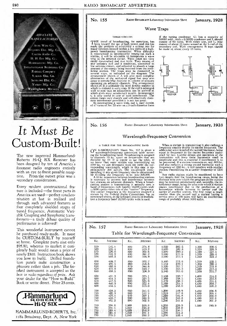
240 RADIO BROADCAST ADVERTISER
ASSOCIATE
,MANUl-ACTURE
ACME Wire Co. %Bi- .JAMIN Elcc. Mfg. CoV
CARTER Radio Co.
H. H. EBY Mfg. Co.
H AMMAKil ND Mfg. Co.
IMIKNVMONAI. Resistance Co.
RADIALL CompanySAMSON Elcc. Co.
SANGA.MO Elec. Co.
YAXLF.Y Mfg. Co.
\\ estinghouse Mu \iu\
It Must BeCustonvBuilt!
The new improved Hammarlund'Roberts Hi-Q SIX Receiver has
been designed by ten of America's
foremost radio engineers entirelywith an eye to finest possible recep-tion. From the outset price was a
secondary consideration.
Every modern constructional fea-
ture is included the finest parts in
America are used perfect synchro-nization at kst is realized and
through such advanced features as
four completely shielded stages of
tuned frequency, Automatic Vari-
able Coupling and Symphonic trans-
formers a truly deluxe quality of
performance is achieved!
This wonderful instrument cannotbe purchased ready-made. It mustbe CUSTOM-BUILT by yourselfat home. Complete parts cost only$95.80, whereas to market it com-
pletely built would mean a price of
nearly $300. Instruction book shows
you how to build. Drilled founda-
tion panels make construction a
pleasure rather than a job. The fin-
ished instrument is accepted as the
best in radio regardless of price. Ask
your dealer for the "How to Build"
Book or write direct. Price 25 cents.
f JicimmarlundI R.O B El RJT SV Hi Q- SIX
HAMMARLUND-ROBERTS, Inc.
1182 Broadway, Dept. A, New York
No. 155 RADIO BROADCAST Laboratory Information Sheet
Wave Traps
January, 1928
THREE CIRCUITS
THE trend of broadcasting, for sometime, hasbeen toward the use of high power, and this has
made the problem of selectivity a serious one for
many listeners located within a few miles of a high-
power broadcasting transmitter. When difficultyis experienced in satisfactorily tuning-out such astation, it will be advisable to incorporate a wavetrap in the antenna circuit. Wave traps are veryeasily constructed and cost little. They consist of
any ordinary coil and a condenser, connected in
the antenna circuit, and adjusted to absorb a largeamount of the energy being received from the inter-
fering station. The traps may be connected inseveral ways, as indicated on the diagram. Thearrangement shown at A will give most completeelimination of the undesired signal but may alsocause a considerable decrease in volume of stations
operating on adjacent channels. The arrangementshown at B is probably the most flexible manner in
which to connect a wave trap. If the coil is arrangedwith several taps an adjustment can be arrived atwhich gives most satisfactory results. ArrangementC is only useful in case of mild interference. Thecircuit tunes very sharply and will effectively elimi-nate interference provided it is not too great.
In constructing a wave trap, coil L may consistof 47 turns of No. 22 wire on a 3-inch diameter form
if the tuning condenser Ci has a capacity of0.0005 mfd.; with a 0.00035 condenser coil L shouldconsist of 60 turns. With either size, coil Li mayconsist of about 15 turns wound at the b end of thesecondary coil. With arrangement B taps shouldbe made at about every 10 turns.
No. 156 RADIO BROADCAST Laboratory Information Sheet January, 1928
Wavelength-Frequency Conversion
A TABLE FOR THE BROADCASTING BAND
ON LABORATORY Sheet No. 157 is given a
wavelength-frequency conversion table cover-
ing the broadcasting band. Broadcasting is assignedto channels 10 kc. apart on frequencies that aredivisible by 10. It is simple to use the table. Ifwe knew that some station was transmitting on1000 kc. we can determine from the table the cor-
responding wavelength, which in this case is ap-proximately 300 meters. The wavelength corre-
sponding to any given frequency can be determinedby dividing the frequency in kc. into 300,000.A 10-kc. separation between broadcasting stations
is necessary to prevent bad interference betweentwo stations on adjacent channels. When a broad-casting station is transmitting it actually uses aband of frequencies (side bands) 10,000 cycles wide
5000 cycles either side of the "carrier" frequency.The carrier frequency is the frequency assigned astation by the Federal Radio Commission, but asmentioned above, in the ordinary process of modula-tion a frequency band 10,000 cycles wide is used.
When a station is transmitting it also radiates afrequency exactly double its carrier frequency. Theadditional wave is called the second harmonic, beingequal in frequency to the carrier frequency multi-
plied by two. Careful design and operation of thetransmitter will keep these harmonics small in
amplitude and this is essential if interference is tobe prevented. If a station transmits on, say, 600 kc.and also radiates a strong second harmonic with afrequency of 1200 kc., it will interfere with anotherstation transmitting on a carrier frequency of 1200kc.
Any radio station might be considered to havetwo ranges; first the broadcasting range, being thedistance area over which the program on the station
may be received satisfactorily and, secondly, the in-
terference range, being the area over which a stationcauses interference due to the production of a
heterodyne whistle between its carrier and thecarrier of another station. The first range is muchsmaller than the second and a station having aservice area of 100 miles will have an interference
range of probably about 1000 miles.
No. 157 RADIO BROADCAST Laboratory Information Sheet January, 1928

RADIO BROADCAST ADVERTISER 241
KARAS A-C-FORMERFILAMENT SUPPLY
TYPE 12LIST PRICE
NO HUM!At last you can step down your 1 10 volt A. C. house currentto operate your set with standard A. C. tubes such as
Cunningham, RCA and CeCo,- without having to use separ-ate device for center tap, and with ABSOLUTELY NOHUM. Let the Karas A-C-Former Filament Supply, Type12, replace your "A" Battery and charger. Will operate 8 I J-
voltType 226 or 326 Tubes, 2 2^-voltType 227 or 327 Tubes,and 2 s-volt Type 177 Tubes at one time. Compact, power-ful, sturdy and built the Karas Way by precision methods.Write for complete information about the new Karas A-C-Former and also data on the Knickerbocker 4 and Karas2-Dial Equamatic.
KARAS ELECTRIC COMPANY4033-A North Rockwell Street Chicago
Two Aids to
Better Radio
MODERN"B" Compact
Type M Transformers
Fp improve your set or get the best results
with any set you contemplate building, in-
stall Modern Type M Transformers, andthen use a Modern "B" Compact the
dependable B current supply.
Modern radio products are designed andnanufactured by engineers who know howo get results. They are guaranteed to
serve you to your satisfaction and you are
not enjoying radio to the fullest extent if
you have not installed Modern Type MTransformers and a Modern "B" Compact.
Write for Type M audio amplifier circuits and book-let on "B" power unit operation. Address Dept.RBl.
THE MODERN ELECTRIC MFG. CO.Toledo, Ohio
Scientific measurement
of inductance has madeHammarlund Space-wound Coils the most
efficient and dependableever devised.
Hammarlund Coil Inductance
Scientifically Measured
NOT very long ago, so many turns of wire on such and suchsize core were considered accurate enough for inductance
measurement.
But in this age of multi-tuned, single-control circuits, guess-work is out of the question. Coils must be matched to thefinest degree.
Not satisfied merely with producing the most efficient type of
coil, Hammarlund devised the instrument pictured above, toinsure accurate measurement of inductance values.
You can depend on Hammarlund precision. It means standard-ized quality and assurance that you get what you pay for.
Your dealer sells Hammarlund MatchedCoils for the latest popular circuits.
HAMMARLUND MANUFACTURING COMPANY424-438 West 33rd Street, New York
More than a score
of radio designersofficially specifyHammarlundPre-cision Products
for their newestcircuits
I lf C^ B^tto*- faocUry
Hammarlund^1 PRECISION
PRODUCTS
Dealer inquiriesinvited concerningseveral new andappealing Ham-marlund develop-ments, having awide sales de-
mand.
Electrostatic condensersfor all purposes
WIRELESSSPECIALTYAPPARATUSCOMPANYJamaica PlainDoston, Mass.
Why not subscribe to Radio
Broadcast? By the year only
$4.00; or two years, $6.00,
saving $2.40. Send direct to
Doubleday, Page & Company,Garden City, New York.
EBYSPECIAL CIRCUITPACKAGES
BINDING
POSTS
15c

242 RADIO BROADCAST ADVERTISER
Write
for this
BookThe famous Lynch 5 tube
de Luxe Deck. Simplifieshome set-BuiIding at great-
ly reduced cost- Also the
popular Lynch CompleteResistance Line. Fullydescribed in this booklet.
Learn the Usefulnessof "Resistance in
Radio"
R\.DIOfans, set-build-
ers, and engineerswill find a wealth of
reliable, boiled-down, and
interesting information in
"Resistance the 'ControlValve' of Radio." Sim-
ply written and clearlyillustrated. Concisely pre-sents the latest informa-tion on resistance coupledamplification, the functionof resistance in a circuit,
circuit arrangements on
equalizers, and other radio
matters of interest and
importance. This valu-
able hand-book on resist-
ance in radio is worth dol-
lars you can get a copyfor only 25 cents.
Write for this book
ARTHUR H. LYNCH, Inc.
1775 Broadway at 57th Street
General Motors Bid?., New York, N. Y.
Sales offices in most large cities
Arthur H. Lynch, Inc.1775 BroadwayNew York City
Gentlemen:
Please send me a copy of your new booklet "Resistance
the 'Control Valve' of Radio." I am enclosing 25 cents.
Name
Street
City State. . R. B.
No. 158 RADIO BROADCAST Laboratory Information Sheet January, 1928
The Three-Tube Roberts Reflex
CIRCUIT CONSTANTS
'"PHERE have been many requests from readersfor further information on the Roberts 3-tube
receiver illustrated in the August, 1927 issue ofRADIO BROADCAST on page 2(h*. This receiver is areflex set consisting of a stage of r.f. amplification,a regenerative detector, one stage of reflexed
transformer-coupled audio amplification, followedby another straight audio stage. The circuit, whichwas not given in the article mentioned above, andwhich many readers have requested, is publishedon Laboratory Sheet No. 159. The list of parts is
given below.
Li, La R. F. transformer. L may consist of 45turns of No. 24 wire wound on a 3-inchtube. Li should contain 40 turns of No. 24wire with a tap at each 10 turns. Li shouldbe wound alongside the filament end of Lz.
Lj, Li, Ls Interstage r.f. transformer. Ls and Lihave the same specifications as Li and Lwith the exception that Ls should be woundwith No. 26 or No. 28 wire and should onlybe tapped at the exact center instead of at
every 10 turns. That end of Ls nearest thegrid end of Lt should connect to the plateof the r.f. tube, the center tap connects totransformer Ta, and the other end of Ls con-nects to the neutralizing condenser. LB is a
movable tickler coil consisting of 20 turns ofNo. 26 on a 1 \ inch tube.
Ti, Ts Any good audio transformers.T:t Any good output transformer.Ci, C:r O.0005-mfd. variable condensers.Si Antenna tap switch.S Filament switch.
Ji Double-circuit interstage jack..!_ Single-circuit jack.V Volume control, 50,000-ohm variable resistanceCa Neutralizing condenser, 0.000015 mfd.C9 Grid condenser, 0.00025 mfd.Hs 4-megohm grid leak.
Ri 10-ohm rheostat.R-i 0.5-ampere fixed filament control resistance.C4 0.001-mfd. fixed condenser.Ca 0.0001-mfd. fixed condenser.C6 0.00025-mfd. fixed condenser.
Eleven binding postsThree sockets
Hook-up wireFor best results a power tube should be used in
the last socket. If a 171 type tube is used with 180volts on the plate, the C bias required is 40.5 volts.When the receiver has been completed it should
be neutralized by tuning-in some station, adjustingthe tickler until the detector oscillates and a whistleis heard and then varying the neutralizing condenseruntil the whistle changes in pitch the least amount(its loudness will change* considerably) as Ci is
varied.
No. 159 RADIO BROADCAST Laboratory Information Sheet January 1928
The Three-Tube Roberts Reflex
No. 160 RADIO BROADCAST Laboratory Information Sheet January, 1928
Fading
HOW IT MAY BE PLOTTED
f~\N THIS Laboratory Sheet is published a curve^ showing how the signal strength from stationWGV varied over a period of about 10 minutes duringa fading test on this station made during the 'earlypart of November.Anyone can make these measurements. To make
fading measurements of this sort the only instru-ment needed is a 1.5-or 2-mA. milliammeter. Themeter is connected in the B plus lead to the detectortube; it will read about 1 mA. if the detector is a201 -A type tube using a grid leak and condenser fordetection with 45 volts on the plate. When a signalis tuned-in the meter deflection will decrease, theamount of the decrease depending upon the strengthof the signals. If the meter deflection with the signaltuned-in is subtracted from the meter deflectionwhen not receiving a signal, the difference will bethe amount the meter deflection has changed dueto the signal. If the normal plate current is 1 mA.and the signal causes the values to decrease to 0.6mA. then the deflection due to the signal is 0.4 mA.If this value varies with time it indicates fadingand can be plotted as a curve, as shown on thisSheet. An examination of this curve indicates thatat the start of the test the meter deflection due tothe signal was 0.5 mA. but that after about oneminute the signal strength quickly fell to 0.25 mA.
and then increased and decreased several times in
rapid succession.
0.1 34567TIME IN MINUTES

RADIO BROADCAST ADVERTISER 245
Constant
Accuracy!
[TRUVOLTAn All-Wire
Variable
Voltage Control
Install Truvolt in the
B'Eliminator you are con'
structing and vary yourvoltage exactly. A newtype wire variable high re'
sistance kept cool by its
greater radiation surface -
like an air cooled motor.
Develops but the tem-
perature of other resist-
ances of like size.; hence is
permanently accurate andlasts indefinitely. Positive
metallic contact alwaysand 30 exact readings of
resistance.
TypeResistance
Ohms
T'5 o to 500T-io o to 1,000T'2O O tO 2,OOO
T-5o o to 5,000T-ioo o to 10,000T-2OO O tO 2O,OOO
T-25O o to 25,000
T'5oo o to 50,000
Current
Milliamperes
224158112
71
50
35
. 32
22.5
Price $3.50 eachAll rated at 25 watts.
At Your Dealers
Also a full line of WireFixed Resistances
Write for free
Hook-up Circular
''This Is AnEliminator Year"
Dept. 14B, 175 Varick Street
New York
ELECTRAD
LEA
ImprovedReception
Get it with the
CARBORUNDUMREG. U. S.PAT. OFF.
GRID LEAKONE certain way of getting better and clearer receptionis to slip a Carborundum Grid Leak into your set.
(& Things will quiet down instantly. Carborundum GridLeaks do not disintegrate hence they are quiet. Theyare solid, fixed, dense rods ofCarborundum. They assure
an uninterrupted flow of current. They banish GridLeak noises.
<I Carborundum Grid Leaks are tested at the maximumoperating grid voltage, namely 5 volts, and Resistors
at 90 volts.
From your dealer, or direct
Send for Hook-Up Booklet D-2
THE CARBORUNDUM COMPANY, NIAGARA FALLS, N. Y.CANADIAN CARBORUNDUM Co., LTD., NIAGARA FALLS, ONT.
Sales Offices and Warehouses in New York, Chicago, Boston, Philadelphia, Cleveland, DetroitCincinnati, Pittsburgh, Grand Rapids, MilwaukeeThe Carborundum Co., Ltd., Manchester, Eng.Deutsche Carborundum Werke, Dusseldorf, Ger.
V Carborundum !> the Reeisterol Trade Nw^ oou Cubide. TblB True Mirk ia tbe cic
! uged 1>J The Carborundum f"nmr*nj for Sill.
IBive prupirtjr of Tbe Carburuadum Cump*uj.
RADIO PANELSBAKELITE HARD RUBBER
Cut, drilled and engraved to order. Send rough sketchfor estimate. Our complete Cataloe on Pant-Is, Tubes andRods all of genuine ttukelite or Hard Rubber mailedon request-
STARRETT MFG. CO.521 S. Green Street Chicago, III.
BROWNING-DRAKE BLUE PRINTS?
Write to
Radio Broadcast MagazineBooklet Department
Garden City New York$1.00 per set
Independent Radio Corporation
Manufacturers of
Precision Radio Apparatus
1516 Summer Street Philadelphia
111T'l
>
da on
.Write for my Big 1928 Radio Catalogjust off the press. Thousands
marvelous bargains in nation-ally advertised goods. All theLATEST I^ RADIOS andequipment Lowestwhole-
All aboutlrouble finding?^
FREE Log andCall Book and Cat-alog. Get your copy to-""
day. Send postcard now!American Auto & Radio Mfg.
HARRY SCHWARTZBUKa. PRRS.Dipt. 123 American Radio flldg., Kansas City. Ml. 3 I

246 RADIO BROADCAST ADVERTISER
"RADIO BROADCASTS" DIRECTORY OFMANUFACTURED RECEIVERS
1 A coupon will be found on page 258. All readers who desire additional
information on the receivers listed below need only insert the proper num-bers in the coupon, mail it to the Service Department of RADIO BROADCAST,and full details will be sent. New sets are listed in this space each month.
KEY TO TUBE ABBREVIATIONS99 60-mA. filament (dry cell)
01-A Storage battery 0.25 amps, filament12 Power tube (Storage battery)71 Power tube (Storage battery)16-B Half-wave rectifier tube80 Full-wave, high current rectifier
81 Half-wave, high current rectifier
Hmu High-Mu tube for resistance-coupled audio20 Power tube (dry cell)
10 Power Tube (Storage battery)00-A Special detector13 Full-wave rectifier tube26 Low-voltage high-current a. c. tube27 Heater type a. c. tube
DIRECT CURRENT RECEIVERSNO. 424. COLONIAL 26
Six tubes; 2 t. r. f. (01-A), detector (12), 2 trans-
former audio (01-A and 71). Balanced t. r. f. One tothree dials. Volume control: antenna switch and poten-tiometer across first audio. Watts required: 120. Con-sole size: 34 x 38 inches. Headphone connections.The filaments are connected in a series parallel arrange-ment. Price $250 including power unit.
NO. 425. SUPERPOWERFive tubes: All 01-A tubes. Multiplex circuit. Two
dials. Volume control: resistance in r. f. plate. Wattsrequired: 30. Antenna: loop or outside. Cabinet sizes:
table, 27 x 10 x 9 inches; console, 28 x 50 x 21.Prices:
table, $135 including power unit; console, $390 includ-
ing power unit and loud speaker.
A. C. OPERATED RECEIVERS,
NO. 508. ALL-AMERICAN 77, 88, AND 99
Six tubes; 3 t. r. f. (26), detector (27), 2 transformeraudio (26 and 71). Rice neutralized t. r. f. Single drumtuning. Volume control: potentiometer in r. f. plate.Cabinet sizes: No. 77, 21 x 10 x 8 inches; No. 88 Hiboy,25 x 38 x 18 inches; No. 99 console, 27{ x 43 x 20 inches.
Shielded. Output device. The filaments are suppliedby means of three small transformers. The plate supplyemploys a gas-filled rectifier tube. Voltmeter in a. c.
supply line. Prices: No. 77, $150, including power unit;No. 88, $210 including power unit; No. 99, $285 in-
cluding power unit and loud speaker.
NO. 509. ALL-AMERICAN "DUET"; "SEXTET"Six tubes; 2 t. r. f. (99), detector (99), 3 transformer
audio (99 and 12). Rice neutralized t. r. f. Two dials.
Volume control: resistance in r. f. plate. Cabinet sizes:
"Duet," 23 x56x 165 inches; "Sextet," 22J x 13 J x 15Jinches. Shielded. Output device. The 99 filaments areconnected in series and supplied with rectified a. c.;while 12 is supplied with raw a. c. The plate and fila-
ment supply uses gaseous rectifier tubes. Milliammeteron power unit. Prices: "Duet," $160 including powerunit; "Sextet," $220 including power unit and loudspeaker.
NO. 511. ALL-AMERICAN 80, 90, AND 115
Five tubes; 2 t. r. f. (99), detector (99), 2 transformeraudio (99 and 12). Rice neutralized t. r. f. Two dials.
Volume control: resistance in r. f. plate. Cabinet sizes:No. 80, 23i x 12} x 15 inches; No. 90, 37| x 12 x 121inches; No. 115 Hiboy, 24 x 41 x 15 inches. Coils indi-
vidually shielded. Output device. See No. 503 for
power supply. Prices: No. 80, $135 including powerunit; No. 90, $145 including power unit and compart-ment; No. 115, $170 including power unit, compart-ment, and loud speaker.
NO. 510. ALL-AMERICAN 7
Seven tubes; 3 t. r. f. (26), 1 untuned r. f. (26), detec-tor (27), 2 transformer audio (26 and 71). Rice neutral-ized t. r. f. One drum. Volume control: resistance in r. f.
plate. Cabinet sizes: "Sovereign" console, 30^ x 601x 19 inches; "Lorraine" Hiboy, 25J x 53} x 17} inches;"Forte" cabinet, 25{ x 13} x 17j inches. For filamentand plate supply: See No. 508. Prices: "Sovereign"$460; "Lorraine'
r
$360; "Forte" $270. All prices includepower unit. First two include loud speaker.
NO. 401, AMRAD AC9Six tubes; 3 t. r. f. (99), detector (99), 2 transformer
(99 and 12). Neutrodyne. Two dials. Volume control :
resistance across 1st audio. Watts consumed: 50. Cabi-net size: 27 x 9 x 11 J inches. The 99 filaments are con-nected in series and supplied with rectified a. c., whilethe 12 is run on raw a. c. The power unit, requiringtwo 16-B rectifiers, is separate and supplies A. B. and Ccurrent. Price $142 including power unit.
NO. 402. AMRAD ACSFive tubes. Same as No. 401 except one less r. f.
stage. Price $125 including power unit.
NO. 536. SOUTH BENDSix tubes. One control. Sub-panel shielding. Binding
Posts. Antenna: outdoor. Prices: table, $130, BabyGrand Console, ISldS.
NO. 537. WALBERT 26
Six tubes; five Kellogg a. c. tubes and one 71. Twocontrols. Volume control: variable plate resistance.Isofarad circuit. Output device. Battery cable. Semi-shielded. Antenna: 50 to 75 feet. Cabinet size: 1OJ x29J x 16i inches. Prices: $215; with tubes, $2.50
NO. 484. BOSWORTH, BSFive tubes; 2. t. r. f. (26), detector (99), 2 transformer
audio (special a. c. tubes). T. r. f. circuit. Two dials.
Volume control: potentiometer. Cabinet size: 23 x 7x 8 inches. Output device included. Price $175.
NO. 406. CLEARTONE 110
Five tubes; 2. t. r. f., detector, 2 transformer audio.All tubes a. c. heater type. One or two dials. Volumecontrol: resistance in r. f. plate. Watts consumed: 40.Cabinet size varies. The plate supply is built in thereceiver and requires one rectifier tube. Filament sup-ply through step down transformers. Prices range from$175 to $375 which includes 5 a. c. tubes and one recti-fier tube.
NO. 407. COLONIAL 25
Six tubes; 2. t. r. f. (01-A), detector (99), 2 resistanceaudio (99). 1 transformer audio (10). Balanced t. r. f.
circuit. One or three dials. Volume control: Antennaswitch and potentiometer on 1st audio. Watts con-sumed: 100. Console size: 34 x 38 x 18 inches. Outputdevice. All tube filaments are operated on a. c. exceptthe detector which is supplied with rectified a. c. fromthe plate supply. The rectifier employs two 16-b tubes.Price $250 including built-in plate and filament supply.
NO. 507. CROSLEY 602 BANDBOXSix tubes; 3. t. r. f. (26), detector (27), 2 transformer
audio (26 and 71). Neutrodyne circuit. One dial, Cabinetsize: 17i x 5} x 7| inches. The heaters for the a. c. tubesand the 71 filament are supplied by windings in B unittransformers available to operate either on 25 or 60cycles. The plate current is supplied by means ofrectifier tube. Price $65 for set alone, power unit $60.
NO. 408. DAY-FAN "DE LUXE"Six tubes; 3 t. r. f., detector, 2 transformer audio. All
01-A tubes. One dial. Volume control: potentiometeracross r. f. tubes. Watts consumed: 300. Console size:30 x 40 x 20 inches. The filaments are connected inseries and supplied with d. c. from a motor-generatorset which also supplies B and C current. Output de-vice. Price $350 including power unit.
NO. 409. DAYCRAFT 5
Five tubes; 2 t. r. f., detector, 2 transformer audio.All a. c. heater tubes. Reflexed t. r. f. One dial. Volumecontrol: potentiometers in r. f. plate and 1st audio.Watts consumed: 135. Console size: 34 x 36 x 14 inches.
Output device. The heaters are supplied by means ofa small transformer. A built-in rectifier supplies Band C voltages. Price $170, less tubes. The followinghave one more r. f. stage and are not reflexed; Day-craft 6, $195; Dayrole, 6, $235; Dayfan 6, $110. All
prices less tubes.
NO. 469. FREED-EISEMANN NRIISix tubes; 3 t. r. f. (01-A), detector (01-A), 2 trans-
former audio (01-A and 71). Neutrodyne. One dial.Volume control: potentiometer. Watts consumed: 150.Cabinet size: 19} x 10 x 101 inches. Shielded. Outputdevice. A special power unit is included employing arectifier tube. Price $225 including NR-411 power unit.
. NO. 487. FRESHMAN 7F-ACSix tubes; 3 t. r. f. (26), detector (27), 2 transformer
audio (26 and 71). Equaphase circuit. One dial. Volumecontrol: potentiometer across 1st audio. Console size:
24Jx 411 x 15 inches. Output device. The filaments andheaters and B supply are all supplied by one power unit.The plate supply requires one 80 rectifier tube. Price$175 to $350, complete.
NO. 421. SOVEREIGN 238
Seven tubes of the a. c. heater type. Balanced t. r. f.
Two dials. Volume control: resistance across 2nd audio.Watts consumed: 45. Console size: 37 x 52 x 15 inches.The heaters are supplied by a small a. c. transformer,while the plate is supplied by means of rectified a. c.
using a gaseous type rectifier. Price $325, includingpower unit and tubes.
NO. 517. KELLOGG 510, 511, AND 512
Seven tubes; 4 t. r. f., detector, 2 transformer audio.All Kellogg a. c. tubes. One control and special zoneswitch. Balanced. Volume control: special. Output de-vice. Shielded. Cable connection between power supplyunit and receiver. Antenna: 25 to 100 feet. Panel 7(3x 27.; inches. Prices: Model 510 and 512, consoles, $495complete. Model 511, consolette, $365 without loudspeaker.
NO. 496. SLEEPER ELECTRICFive tubes; four 99 tubes and one 71. Two controls.
Volume control: rheostat on r. f. Neutralized. Cable.Output device. Power supply uses two 16-B tubes.Antenna: 100 feet. Prices: Type 64, table, $160; Type65, table, with built-in loud speaker, $175; Type 66,table, $175; Type 67, console, $235; Type 78, console,$265.
NO. 538. NEUTROWOUND MASTER ALLECTRICSix tubes; 2 t. r. f. (01-A), detector (01-A), 2 audio
(01-A and two 71 in push-pull amplifier). The 01-Atubes are in series, and are supplied from a 400-mA.rectifier. Two drum controls. Volume control: variableplate resistance. Output device. Shielded. Antenna:50 to 100 feet. Price: .1360.
NO. 413. MARTISix tubes: 2 t. r. f., detector, 3 resistance audio. All
tubes a. c. heater type. Two dials. Volume control-resistance in r. f. plate. Watts consumed: 38. Panel size7 x 21 inches. The built-in plate supply employs one16-B rectifier. The filaments are supplied by a smalltransformer. Prices: table, $235 including tubes andrectifier; console, $275 including tubes and rectifier;
console, $325 including tubes, rectifier, and loudspeaker.
NO. 417 RADIOLA 28
Eight tubes; live type 99 and one type 20. Drumcontrol. Super-heterodyne circuit. C-battery connec-tions. Battery cable. Headphone connection. Antenna:loop. Set may be operated from batteries or from thepower mains when used in conjunction with the model104 loud speaker. Prices: $260 with tubes, batteryoperation; $570 with model 104 loud speaker, a. c.
operation.
NO. 540 RADIOLA 30-AReceiver characteristics same as No. 417 except that
type 71 power tube is used. This model is designed to
tamed in lower part ot cabinet. Jbither a short inor long outside antenna may be used. Cabinet size:42Jx 29 x 17 J inches. Price: $495.
NO. 541. RADIOLA 32
This model combines receiver No. 417 with the model104 loud speaker. The power unit uses two type 81tubes and a type 10 power amplifier. Loop is completelyenclosed and is revolved by means of a dial on the panel.Models for operation from a. c. or d. c. power mains.Cabinet size: 52 x 72 x 17} inches. Price: $895.
NO. 539 RADIOLA 17
Six tubes; 3 t. r. f. (26), detector (27), 2 transformeraudio (26 and 27). One control. Illuminated dial.Built-in power supply using type 80 rectifier. Antenna:100 feet. Cabinet size: 25f, x 7J x 8J. Price: $130without accessories.
NO. 545. NEUTROWOUND, SUPER ALLECTRICFive tubes; 2 t. r. f. (99), detector (99), 2 audio (99
and 71). The 99 tubes are in series and are supplied froman 85-mA. rectifier. Two drum controls. Volume con-trol: variable plate resistance. Output device. Antenna:75 to 100 feet. Cabinet size: 9 x 24 x 11 inches. Price:$150.
NO. 490. MOHAWKSix tubes; 2 t. r. f., detector, 2 transformer audio. All
tubes a. c. heater type except 71 in last stage. One dial.Volume control: rheostat on r. f. Watts consumed: 40.Panel size: 12\ x 8 inches. Output device. The heatersfor the a. c. tubes and the 71 filament are supplied bysmall transformers. The plate supply is of the built-in
type using a rectifier tube. Prices range from $65 to$245.
NO. 522. CASE, 62B AND 62C
McCullough a. c. tubes. Drum control. Volume con-trol; variable high resistance in audio system. C-batteryconnections. Semi-shielded. Cable. Antenna: 100 feet.Panel size: 7 x 21 inches. Prices: Model 62B, completewith a. c. equipment, $185; Model 62 C, complete witha. c. equipment, $235.
NO. 523. CASE, 92 A AND 92 CMcCullough a. c. tubes. Drum control. Inductive
volume control. Technidyne circuit. Shielded. Cable.C-battery connections. Model 92 C contains outputdevice. Loop operated. Prices: Model 92 A, table, $350;Model 92 C, console, $475.
BATTERY OPERATED RECEIVERS
NO. 542. PFANSTIEHL JUNIOR SIXSix tubes: 3 t. r. f. (01-A), detector (01-A), 2 audio.
Pfanstiehl circuit. Volume control: variable resistance inr. f. plate circuit. One dial. Shielded. Battery cable. C-battery connections. Etched bronze panel. Antenna:outdoor. Cabinet size: 9 x 20 x 8 inches. Price: $80, with-out accessories.
NO. 512. ALL-AMERICAN 44, 45, AND 66
Six tubes; 3 t. r. f. (01-A, detector) 01-A, 2 trans-former audio (01-A and 71). Rice neutralized t. r. f.
Drum control. Volume control: rheostat in r. f. Cabinetsizes: No. 44, 21 x 10 x 8 inches; No. 55. 25 x 38 x 18inches; No. 66, 27J x 43 x 20 inches. C-battery connec-tions. Battery cable. Antenna: 75 to 125 feet. Prices:No. 44, $70; No. 55, $125 including loud speaker; No.66, $200 including loud speaker.
NO. 428. AMERICAN C6Five tubes; 2 t. r. f. detector, 2 transformer audio.
All 01-A tubes. Semi balanced t. r. f. Three dials. Platecurrent 15mA. Volume control: potentiometer. Cabinetsizes: table, 20 x 8! x 10 inches; console, 36 x 40 x 17inches. Partially shielded. Battery cable. C-batteryconnections. Antenna: 125 feet. Prices: table, $30console, $65 including loud speaker.

RADIO BROADCAST ADVERTISER 247
New AERO Circuits
For Either Battery
or A. C. OperationThe Improved Aero-Dyne 6, and the
Aero 7 popular new circuits are
built around these marvelous coils
You Should Learn About Them Now!
Proper constants for A. C. operation of
the improved Aero-Dyne 6 and the AeroSeven have been studied out. and these
excellent circuits are now adaptable to
either A. C. or battery operation. A. C.
blue prints are packed in foundation
units. They may also be obtained bysending 25e for each direct to the factory.
AERO Universal Tuned Radio Frequency Kit
Especially designed for the Improved Aero-Dyne 6. Kit consists of 4 twice-matchedunits. Adaptable to 201-A, 199. 112, and thenew 240 and A. C. tubes. Tuning range be-low 200 to above ">.">o meters.This kit will make any circuit better in
selectivity, tone and range. Will eliminatelosses and give the greatest receiving effi-
ciency.
Code No. U- 16 (for .01105 Cond.) .. .$15.00Code No. U-163 (for .00035 Cond.)... 15.00
AERO Seven Tuned Radio Frequency Kit
Kspi-cially designed for the Aero 7. Kit con->Kts of 3 twice-matched units. Coils arewound on Bakelite skeleton forms, assuringa 95% air di-electrie. Tuning range frombelow 200 to above 550 meters. Adaptableto 2H1-A. 199, 112, and the new 240 andA. C. tubes.
Code No. U- 12 (for .0005 Cond.) .. .$12.00Code No. U-123 (for .00035 Cond.)... 12.00
MITE All AERO Universal Kits for use in
(inii-il radio frequency circuits have packedin t-ni-ti mil with a fixed primary a tir'n-i-
matched calibration slip showing readingat cadi fised primary AERO Universal Coilat 250 inifl 300 Dieters; all having an ac-rurati' inul similar ciililiratioit. He sure to
keep these slips. They're valuable if you de-cide to add another R.F. Stage to your set.
A NEW SERVICE\\ have arranged to furnish the homo sol builderwith complete Foundation Units for the abovenamed Circuits, drilled and engraved on Westing-house Micarta. Detailed blue-prints for bothbattery and A. C. operation and wiring diagramfor each circuit included with every foundationunit free. Write for information and prirrs.
You should be able to get any of the aboveAero Coils and parts from your dealer. Ifhe should be out of stock order direct
from the factory.
AERO PRODUCTS, Inc.1772 Wilson Ave. Dept. 109 Chicago, 111.
COOLPOWER
Samson Power IHock No. 210 The only block which will supply 500 voltsat 80 mils to two 210 tubes.
Powerize with Samson Units for Best ResultsFor new SAMSON Power Units insure the best there is in radio current supply by
1. Doing away with hum, motor boating and poor voltage regulation.
2. Remaining so cool after 24 hours continuous operation under full load that they will be wellwithin the 20 rise of temperature specified by the A. I. E. E.
3. Being designed to more than meet the specifications adopted by the National Board of Fire Underwriters.
4. Insuring safety against shock because of protected input and output terminals.
5. Insuring for all tubes the correct filament voltages specified by their manufacturers.
6. Compensating for lighting circuit voltage variation by the use of a special input plug andterminal block to which is attached a six ft. flexible rubber-covered connecting cord and plug.
Our Power Units bulletin descriptive of these is free for the asking. In addition, ourconstruction bulletin on many different "B" Eliminators and Power Amplifierswill be sent upon receipt of lOc. in stamps to cover the mailing cost.
\amsonManufacturing Since 1882 Principal Office, CANTON, MASS.
lUaich VOPfl,
6or Uour
Jubes
//TUBES/Could Talk!
They would tell you that only at theprecise and definitely prescribed fila-ment current, or temperature, can theirtonal qualities, clarity and sensitivenessbe brought out to the full. That "A"battery current constantly varies accord-ing to the age of the battery and stateof charge and operation with too littleor too great current is certain deathto efficient tube performance and too
quickly, of the tube itself. That only AMPERITEcan automatically supply and control this exactcurrent despite battery variation as long assufficient current is to be had. That you shouldnever confuse AMPERITE with fixed filamentresistors which do not do the Amperite's job.AMPERITE is sold by dealers everywhere. Price81.10 mounted (in U. S. A.).
Write for FREE "Amperite Book" of the season's best circuit*and latest construction data. Address Dept. K.ll-1
50 Franklin St., New York
Jhe "SELF-ADJUSTING"Rheostat
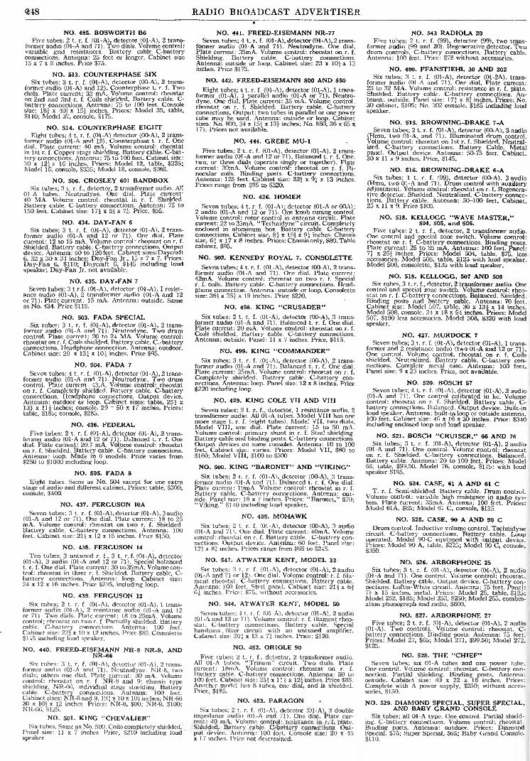
RADIO BROADCAST ADVERTISER
NO. 485. BOSWORTH B6Five tubes; 2 t. r. f. (01-A), detector (01-A), 2 trans-
former audio (01-A and 71). Two dials. Volume control:variable grid resistances. Battery cable. C-batteryconnections. Antenna: 25 feet or longer. Cabinet size
15 x 7 x 8 inches. Price $75.
NO. 513. COUNTERPHASE SIXSix tubes; 3 t. r. f. (01-A), detector (00-A), 2 trans-
former audio (01-A) and 12). Counterphase t. r. f. Twodials. Plate current: 82 mA. Volume control: rheostaton 2nd and 3rd r. f. Coils shielded. Battery cable. C-battery connections. Antenna: 75 to 100 feet. Consolesize: 18| x 40} x 155 inches. Prices: Model 35, table,
$110; Model 37, console, $175.
NO. 514. COUNTERPHASE EIGHTEight tubes; 4 t. r. f. (01-A) detector (00-A), 2 trans-
former audio (01-A and 12). Counterphase t. r. f. Onedial. Plate current: 40 mA. Volume control: rheostatin 1st r. f. Copper stage shielding. Battery cable. C-bat-
tery connections. Antenna: 75 to 100 feet. Cabinet size:
30 x 125 x 16 inches. Prices: Model 12, table, $225;Model 16, console, $335; Model 18, console, $365.
NO. 506. CROSLEY 601 BANDBOXSix tubes; 3 t. r. f., detector, 2 transformer audio. All
01-A tubes. Neutrodyne. One dial. Plate current:40 MA. Volume control: rheostat in r. f. Shielded.
Battery cable. C-battery connections. Antenna: 75 to150 feet. Cabinet size: 17J x 5j x 7|. Price, $55.
NO. 434. DAY-FAN 6
Six tubes; 3 t. r. f. (01-A), detector (01-A), 2 trans-former audio (01-A and 12 or 71). One dial. Platecurrent: 12 to 15 mA. Volume control: rheostat on r. f.
Shielded. Battery cable. C-battery connections. Outputdevice. Antenna: 50 to 120 feet. Cabinet sizes:Daycraft6, 32 x 30 x 34 inches; Day-Fan Jr., 15 x 7 x 7. Prices:
Day-Fan 6, $110; Daycraft 6, $145 including loud
speaker; Day-Fan Jr. not available.
NO. 435. DAY-FAN 7
Seven tubes; 3 t.r.f. (01-A), detector (01-A), I resist-
ance audio (01-A), 2 transformer audio (01-A and 12or 71). Plate current: 15 mA. Antenna: outside. Sameas No. 434. Price $115.
NO. 503. FADA SPECIALSix tubes; 3 t. r. f. (01-A), detector (01-A), 2 trans-
former audio (01-A and 71). Neutrodyne. Two drumcontrol. Plate current: 20 to 24 MA. Volume control:rheostat on r. f. Coils shielded. Battery cable. C.-batteryconnections. Headphone connection. Antenna: outdoor.Cabinet size: 20 x 13J x 10} inches. Price $95.
NO. 504. FADA 7
Seven tubes; 4 t. r. f. (01-A), detector (01 -A), 2 trans-former audio (01-A and 71). Neutrodyne. Two drumcontrol. Plate current: 43,A. Volume control: rheostaton r. f. Completely shielded. Battery cable. C-batteryconnections. Headphone connections. Output device.Antenna: outdoor or loop. Cabinet sizes: table, 25} x13} x 11 J inches; console, 29 - 50 x 17 inches. Prices:
table, $185; console, $285.
NO. 436. FEDERALFive tubes; 2 t. r. f. (01-A), detector (01-A), 2 trans-
former audio (01-A and 12 or 71). Balanced t. r. f. Onedial. Plate current: 20.7 mA. Volume control: rheostaton r. f. Shielded. Battery cable. C-battery connections.Antenna: loop. Made in 6 models. Price varies from$250 to $1000 including loop.
NO. 505. FADA 8
Flight tubes. Same as No. 504 except for one extrastage of audio and different cabinet. Prices: table, $300;console, $400.
NO. 437. FERGUSON IDA
Seven tubes; 3 t. r. f. (01 -A), detector (01 -A), 3 audio(01-A and 12 or 71). One dial. Plate current: 18 to 25mA. Volume control: rheostat on two r. f. Shielded.Battery cable. C-battery connections. Antenna: 100feet. Cabinet size: 21* x 12 x 15 inches. Price $150.
NO. 438. FERGUSON 14
Ten tubes; 3 untuned r. f., 3 t. r. f. (01-A), detector(01-A), 3 audio (01-A and 12 or 71). Special balancedt. r. f. One dial. Plate current: 30 to 35mA. Volume con-trol: rheostat in three r. f. Shielded. Battery cable, C-battery connections. Antenna: loop. Cabinet size:
24 x 12 x 16 inches. Price $235, including loop.
NO. 439. FERGUSON 12
Six tubes; 2 t. r. f. (01-A), detector (01-A), 1 trans-former audio (01-A), 2 resistance audio (01-A and 12or 71). Two dials. Plate current: 18 to 25mA. Volumecontrol; rheostat on two r. f. Partially shielded. Batterycable. C-battery connections. Antenna: 100 feetCabinet size: 225 x 10 x 12 inches. Price $85. Consolette$145 including loud speaker.
NO. 440. FREED-EISEMANN NR-8 NR-9, ANDNR-66
Six tubes: 3 t. r. f. (01-A), detector (01-A), 2 trans-former audio (01-A and 71). Neutrodyne. NR-8, twodials; others one dial. Plate current: 30 mA. Volumecontrol: rheostat on r. f. NR-8 and 9: chassis typeshielding. NR-66, individual stage shielding. Batterycable. C-battery connections. Antenna: 100 feet.Cabinet sizes: NR-8 and 9, 19! x 10 x KM inches; NR-6620 x 101 x 12 inches. Prices: NR-8, $90; NR-9, S100;NR-66, $125.
NO. 501. KING "CHEVALIER"Six tubes. Same as No. 500. Coils completely shielded.
Panel size: 11 x 7 inches. Price, $210 including loudspeaker.
NO. 441. FREED-EISEMANN NR-77Seven tubes; 4 t. r. f. (01 -A), detector (01 -A), 2 trans-
former audio (01-A and 71). Neutrodyne. One dial.
Plate current: 35mA. Volume control: rheostat on r. f.
Shielding. Battery cable. C-battery connections.Antenna: outside or loop. Cabinet size: 23 x 10^ x 13inches. Price $175.
NO. 442. FREED-EISEMANN 800 AND 850
Eight tubes; 4 t. r. f. (01-A), detector (01-A), 1 trans-former (01-A), 1 parallel audio (01-A or 71). Neutro-dyne. One dial. Plate current: 35 mA. Volume control:rheostat on r. f. Shielded. Battery cable. C-batteryconnections. Output: two tubes in parallel or one powertube may be used. Antenna: outside or loop. Cabinetsizes: No. 800, 34 x 155 x 135 inches; No. 850, 36 x 65 x17J. Prices not available.
NO. 444. GREBE MU-1Five tubes; 2 t. r. f. (01-A), detector (01-A), 2 trans-
former audio (01-A and 12 or 71). Balanced t. r. f. One,two, or three dials (operate singly or together). Platecurrent: 30mA. Volume control: rheostat on r. f. Bi-nocular coils. Binding posts. C-battery connections.Antenna: 125 feet. Cabinet size: 225 x 9J x 13 inches.Prices range from $95 to $320.
NO. 426. HOMERSeven tubes; 4 t. r. f. (01-A) ; detector (01-A or OOA) ;
2 audio (01-A and 12 or 71). One knob tuning control.Volume control: rotor control in antenna circuit. Platecurrent: 22 to 25mA. "Technidyne" circuit. Completelyenclosed in aluminum box. Battery cable. C-batteryconnections. Cabinet size, 84 x 19} x 9} inches. Chassissize, 6f x 17x8 inches. Prices: Chassis only, $80. Tablecabinet, $95.
NO. 502. KENNEDY ROYAL 7. CONSOLETTESeven tubes; 4 t. r. f. (01-A), detector (00-A), 2 trans-
former audio (01-A and 71). One dial. Plate current:42mA. Volume control: rheostat on two r. f. Specialr. f. coils. Battery cable. C-battery connections. Head-phone connection. Antenna: outside or loop. Consotettesize: 365 x 355 x 19 inches. Price $220.
NO. 498. KING "CRUSADER"Six tubes; 2 t. r. f. (01-A), detector (00-A), 3 trans-
former audio (01-A and 71). Balanced t. r. f. One dial.
Plate current: 20 mA. Volume control: rheostat on r. f.
Coils shielded. Battery cable. C-battery connections.Antenna: outside. Panel: 11x7 inches. Price, $115.
NO. 499. KING "COMMANDER"Six tubes; 3 t. r. f. (01-A), detector (00-A), 2 trans-
former audio (01-A and 71). Balanced t. r. f. One dial.
Plate current: 25mA. Volume control: rheostat on r. f.
Completely shielded. Battery cable. C-battery con-nections. Antenna: loop. Panel size: 12 x 8 inches. Price$220 including loop.
NO. 429. KING COLE VII AND VIII
Seven tubes; 3 t. r. f., detector, 1 resistance audio, 2transformer audio. All 01-A tubes. Model VIII has onemore stage t. r. f. (eight tubes). Model VII, two dials.
Model VIII, one dial. Plate current: 15 to 50 mA.Volume control: primary shunt in r. f. Steel shielding.Battery cable and binding posts. C-battery connections.Output devices on some consoles. Antenna: 10 to 100feet. Cabinet size: varies. Prices: Model VII, $80 to$160; Model VIII, $100 to $300
NO. 500. KING "BARONET" AND "VIKING"Six tubes; 2 t. r. f. (01-A), detector (00-A), 3 trans-
former audio (01-A and 71). Balanced t. r. f. One dial.
Plate current: 19mA. Volume control: rheostat in r. f.
Battery cable. C-battery connections. Antenna: out-side. Panel size: 18x7 inches. Prices: "Baronet," $70;"Viking," $140 including loud speaker.
NO. 489. MOHAWKSix tubes; 2 t. r. f. (01-A), detector (00-A), 3 audio
(01-A and 71). One dial. Plate current: 40mA. Volumecontrol: rheostat on r. f. Battery cable. C-battery con-nections. Output device. Antenna: 60 feet. Panel size:
125 x &l inches. Prices range from $65 to $245.
NO. 547. ATWATER KENT, MODEL 33
Six tubes; 3 t. r. f. (01-A), detector (01-A), 2 audio(01-A and 71 or 12). One dial. Volume control: r. f. fila-
ment rheostat. C-battery connections. Battery cable.Antenna: 100 feet. Steel panel. Cabinet size: 21 Jx 6f6J inches. Price: $75, without accessories.
NO. 544. ATWATER KENT, MODEL 50
Seven tubes; 4 t. r. f. (01-A), detector (01-A), 2 audio(01-A and 12 or 71). Volume control: r. f. filament rheo-stat. C-battery connections. Battery cable. Specialbandpass . filter circuit with an untuned amplifier.Cabinet size: 20J x 13 x T, inches. Price: $120.
NO. 452. ORIOLE 90
Five tubes; 2 t. r. f., detector, 2 transformer audio.All 01-A tubes. "Trinum" circuit. Two dials. Platecurrent: 18mA. Volume control: rheostat on r. f.
Battery cable. C-battery connections. Antenna: 50 to100 feet. Cabinet size: 25} x 1 15 x 125 inches. Price $85.Another model has 8 tubes, one dial, and is shielded.Price, $185.
NO. 453. PARAGONSix tubes; 2 t. r. f. (01-A), detector (01-A), 3 double
impedance audio (01-A and 71). One dial. Plate cur-rent: -10 inA. Volume control: resistance in r. f. plate.Shielded. Battery cable. C-battery connections. Out-put device. Antenna: 100 feet. Console size: 20 x 45x 17 inches. Price not determined.
NO. 543 RADIOLA 20
F^e tubes; 2 t. r. f. (99), detector (99), two trans-former audio (99 and 20). Regenerative detector. Twodrum controls. C-battery connections. Battery cable.Antenna: 100 feet. Price: $78 without accessories.
NO. 480. PFANSTIEHL 30 AND 302
Six tubes; 3 t. r. f. (01-A), detector (01-2A), trans-former audio (01-A and 71). One dial. Plate current:23 to 32 MA. Volume control: resistance in r. f. plate.Shielded. Battery cable. C-battery connections. An-tenna: outside. Panel size: 17* x 85 inches. Prices: No30 cabinet, $105; No. 302 console, $185 including loudspeaker.
NO. 515. BROWNING-DRAKE 7-ASeven tubes; 2 t. r. f. (Ol-A), detector (00-A), 3 audio
(Hmu, two 01-A, and 71). Illuminated drum control.Volume control: rheostat on 1st r. f. Shielded. Neutral-ized. C-battery connections. Battery Cable. Metalpanel. Output device. Antenna: 50-75 feet. Cabinet,30 x 11 x 9 inches. Price, $145.
NO. 516. BROWNING-DRAKE 6-ASix tubes; 1 t. r. f. (99), detector (OC^A), 3 audio
(Hmu, two 01-A and 71). Drum control with auxiliaryadjustment. Volume control: rheostat on r. f. Regenera-tive detector. Shielded. Neutralized. C-battery connec-tions. Battery cable. Antenna: 50-100 feet. Cabinet25 x 11 x 9. Price $105.
NO. 518. KELLOGG "WAVE MASTER,"504, 505, and 506.
Five tubes; 2 t. r. f., detector, 2 transformer audio.One control and special zone switch. Volume control:rheostat on r. f. C-battery connections. Binding posts.Plate current: 25 to 35 mA. Antenna: 100 feet. Panel-7} x 25J inches. Prices: Model 504, table, $75, lessaccessories. Model 505, table, $125 with loud speakerModel 506, consolette, $135 with loud speaker.
NO. 519. KELLOGG, 507 AND 508Six rubes, 3 t. r. f., detector, 2 transformer audio. One
control and special zone switch. Volume control: rheo-stat on r. f. C-battery connections. Balanced. Shielded.Binding posts and battery cable. Antenna: 70 feetCabinet size: Model 507, table, 30 x 13ix 14 inches.Model 508, console, 84 x 18 x 54 inches. Prices- Model507, $190 less accessories. Model 508, $320 with loudspeaker.
NO. 427. MURDOCK 7
Seven tubes; 3 t. r. f. (01-A), detector (01-A), 1 trans-former and 2 resistance audio (two 01-A and 12 or 71).One control. Volume control: rheostat on r. f. Coilsshielded. Neutralized. Battery cable. C-battery con-nections. Complete metal case. Antenna: 100 feet.Panel size: 9 x 23 inches. Price, not available.
NO. 520. BOSCH 57
Seven tubes; 4 t. r. f. (01-A), detector (01-A), 2 audio(01-A and 71). One control calibrated in kc. Volumecontrol: rheostat on r. f. Shielded. Battery cable. C--
battery connections. Balanced. Output device. Built-inloud speaker. Antenna: built-in loop or outside antenna.100 feet. Cabinet size: 46 x 16 x 30 inches. Price: $340including enclosed loop and loud speaker.
NO. 521. BOSCH "CRUISER," 66 AND 76
Six tubes; 3 t. r. f. (01-A), detector (01-A), 2 audio(01-A and 71). One control. Volume control: rheostaton r. f. Shielded. C-battery connections. BalancedBattery cable. Antenna: 20 to 100 feet. Prices: Model66, table, $93.50. Model 76, console, $175; with loudspeaker $195.
NO. 524. CASE, 61 A AND 61 CT. r. f. Semi-shielded. Battery cable. Drum control.
Volume control: variable high resistance in audio sys-tem. Plate current: 35mA. Antenna: 100 feet. Prices;Model 61A, $85; Model 61 C, console, $135.
NO. 525. CASE, 90 A AND 90 CDrum control. Inductive volume control. Technidyne
circuit. C-battery connections. Battery cable. Loopoperated. Model 90-C equipped with output devicePrices: Model 90 A, table, $225; Model 90 C, console,S350.
NO. 526. ARBORPHONE 25
Six tubes; 3 t. r. f. (01-A), detector (01-A), 2 audio(01-A and 71). One control. Volume control: rheostat.Shielded. Battery cable. Output device. C-battery con-nections. Loftin-White circuit. Antenna: 75 feet. Panel:7 1
. x 15 inches, metal. Prices: Model 25, table, $125-Model 252, $185; Model 253, $250; Model 255, combin-ation phonograph and radio, $600.
NO. 527. ARBORPHONE 27
Five tubes; 2 t. r. f. (01-A), detector (01-A), 2 audio(01-A). Two controls. Volume control: rheostat. C-battery connections. Binding posts. Antenna: 75 feet.Prices: Model 27, $65; Model 271, $99.50; Model 2"2,$125.
NO. 528. THE "CHIEF"Seven tubes; six 01-A tubes and one power tube.
One control. Volume control: rheostat. C-battery con-nection. Partial .shielding. Binding posts. Antenna:outside. Cabinet size: 40 x 22 x 16 inches. Prices:
Complete with A power supply, $250; without acces-
sories, $150.
NO. 529. DIAMOND SPECIAL, SUPER SPECIAL,AND BABY GRAND CONSOLE
Six tubes; all 01-A type. One control. Partial shield-
ing. C-battery connections. Volume control: rheostat.
Binding posts. Antenna: outdoor. Prices: DiamondSpecial, $75; Super Special, $65; Baby Grand Console.$110.

RADIO BROADCAST ADVERTISER 249
^ ^^ V- ^-^^jjf "'-T? ^Hfc "*Pfc
A CompleteAerial Kit
thatsavestime^effortIt is much easier to buy acomplete Belden Aerial Kitwith Beldenamel Aerial
Wire, Belden LightningArrester, etc., than to pickup the many odd items thatare essentialfora good aerial.
Every item in the BeldenAerial Kit is matched for
perfect performance.
Insureyourselfagainst aerialtrouble. Ask your dealer for
a Beldenamel Aerial Kit,
today. A Beldenamel Aerialcannot corrode.
Belden Manufacturing Co.X31Z-A S. Western Ave., Chicago
Aerial Kit
Iii the still of the Arctic NightIn the still of the Arctic night, broken
only by the occasional bark of a far-off
walrus, the Radio Operator cannot leavehis ship, frozen into the ice pack, and runaround the corner to the Radio Shackfor a new filter condenser to replace theone that just blew out.He has got to be sure when he starts
that his equipment is not going to giveout.
That is why Cliff Himoe took TOBECondensers with him on the Bowdoinfor the MacMillan Arctic Expedition.Here is a Radio message just received
from the boat: The TOBE'S are up to the
mark!
"Your filter condenser standing up well on Bowdoin's
transmitter, with no signs of trouble at continuous2000 volts dc regards from the arctic."
Himoe WNP
The University-of-Michigan-Greenland Expedition is also equipped withTOBE Condensers.
Make sure that your Radio Power Equipment includes TOBE Condensers.TOBE Condensers cure condenser worries permanently and painlessly.
Send for Price List B-l
Tobe Deutschmann Companys Cambridge Massachusetts /
WANTED!Radio Dealers
PROFESSIONALSet Builders and Radio Fans
INevery community to introduce and become our
factory Representative on the newest, most rev-
olutionary radio development in the history of
the industry . . . The SUPER HILODYNE Circuit,
a radio circuit that is modern and independent.See December issue of Radio News.
The SUPER HILODYNE is a new basic circuit
employing nine tubes. Its all around performancewill amaze you. You can help repeat Radio Historyand make money by representing us in your com-
munity in your full or spare time. Write TO-DAYfor details. Dept. RB-128.
ALGONQUIN245 Fifth Avenue
ELECTRIC CO., INC.New York City

250 RADIO BROADCAST ADVERTISER
No. 531. KOLSTER, 8A, SB, AND 8C
Eight tubes; 1 t. r. f. (01-A). detector (01-A). 3-audio(two 01-A and one 12). One control. Volume control:rheostat on r. f. Shielded. Battery cable. C-battery con-nections. Model 8A uses 50 to 75 foot antenna; model8B contains output device and uses antenna or detach-able loop; Model 8C contains output device and usesantenna or built-in loop. -Prices: 8A, $185; 8B, $235;8C, $375.
NO. 532. KOLSTER, 6D, 6G, AND 6HSix tubes; 3 t. r. f. (01-A), detector (01-A), 2 audio
(01-A and 12). One control. Volume control: rheostaton r. f. C-battery connections. Battery cable. Antenna :
50 to 75 feet. Model 6G contains output device andbuilt-in loud speaker; Model 6H contains built-in Bpower unit and loud speaker. Prices: Model 6D, $80;Model 6G, $165; Model 6H, $265.
NO. 533. SIMPLEX, SR 9 AND SR 10
Five tubes; 2 t. r. f. (01-A), detector (00-A), 2 audio(01-A and 12). SR 9, three controls; SR 10, two con-trols. Volume control ; rheostat. C-battery connections.Battery cable. Headphone connection. Prices: SR 9,
table, $65; consolette, $95; console, $145. SR 10, table$70; consolette, $95; console, $145.
NO. 534. SIMPLEX, SR 11
Six tubes; 3 t r. f. (01-A), detector (00-A), 2 audio(01-A and 12). One control. Volume control: rheostat.C-battery connections. Battery cable. Antenna: 100feet. Prices; table, $70; consolette, $95; console, $145.
NO. 535. STANDARDYNE, MODEL X 27
Six tubes; 2 t. r. f. (01-A), detector (01-A), 2 audiopower tubes), one control. Volume control: rheostaton r. f. C-battery connections. Binding posts. Antenna'75 feet. Cabinet size: 9 x 9 x 19J inches. Prices: S 27,549.50; S 950, console, with built-in loud speaker,$99.50; S 600, console with built-in loud speaker,$104.50.
NO. 481. PFANSTIEHL 32 AND 322
Seven tubes: 3 t. r. f. (01-A), detector (01-A), 3 audio(01-A and 71). One dial. Plate current: 23 to 32 mA.Volume control: resistance in r. f. plate. ShieldedBattery cable. C-battery connections. Output device.Antenna: outside. Panel: 17f x 8S inches. Prices: No.32 cabinet, $145; No. 322 console, $245 including loudspeaker.
NO. 433. ARBORPHONEFive tubes; 2 t. r. f., detector, 2 transformer audio
All 01-A tubes. Two dials. Plate current: 16mA. Vol-ume control: rheostat in r. f. and resistance in r. f. plate.C-battery connections. Binding posts. Antenna: tapsfor various lengths. Cabinet size: 24 x 9 x 10J inches.Price: $65.
NO. 431. AUDIOLA 6
Six tubes; 3 t. r. f. (01-A), detector (00-A), 2 trans-former audio (01-A and 71). Drum control. Plate cur-rent: 20mA. Volume control: resistance in r. f. plateStage shielding. Battery cable. C-battery connection.Antenna: 50 to 100 feet. Cabinet size: 28J x 11 x 14iinches. Price not established.
NO. 432. AUDIOLA 8
Eight tubes; 4 t. r. f. (01-A), detector (00-A), 1 trans-former audio (01-A), push-pull audio (12 or 71). Bridgebalanced t. r. f. Drum control. Volume control: resis-tance in r. f. plate. Stage shielding. Battery cable. C-battery connections. Antenna: 10 to 100 feet. Cabinetsize: 28j x 11 x 14^ inches. Price not established.
NO. 542 RADIOLA 16
Six tubes; 3 t. r. f. (01-A), detector (01 A), 2 trans-former audio (01-A and 112). One control. C-batteryconnections. Battery cable. Antenna: outside. Cabinetsize: 16 x 8J x "i\ inches. Price: S69.50 without acces-sories.
NO. 456. RADIOLA 20
Five tubes; 2 t. r. f. (99), detector (99), 2 transformeraudio (99 and 20). Balanced t. r. f. and regenerative de-tector. Two dials. Volume control: regenerative.Shielded. C-battery connections. Headphone connec-tions. Antenna: 75 to 150 feet. Cabinet size: 19j xHi x 16 inches. Price $115 including all tubes.
NO. 457. RADIOLA 25
Six tubes; five type 99 and one type 20. Drum con-trol. Super-heterodyne circuit. C-battery connections.Battery cable. Headphone connections. Antenna: loop.Set may be operated from batteries or from power mainswhen used with model 104 loud speaker. Price; $165with tubes, for battery operation. Apparatus for opera-tion of set from the power mains can be purchasedseparately.
NO. 493. SONORA FSeven tubes; 4. t. r. f. (01-A), detector (00-A), 2 trans-
former audio (01-A and 71). Special balanced t. r. f.
Two dials. Plate current: 45mA. Volume control:rheostat in r. f. Shielded. Battery cable. C-batteryconnections. Output device. Antenna: loop. Consolesize: 32 x 45j x 17 inches. Prices range from $350 to$450 including loop and loud speaker.
NO. 494. SONORA ESix tubes; 3 t. r. f. (01-A), detector (00-A), 2 trans-
former audio (01-A and 71). Special balanced t. r. f.
Two dials. Plate current : 35 to 40mA. Volume control :
rheostat on r. f. Shielded Battery cable. C-batteryconnections. Antenna: outside. Cabinet size: varies.Prices: table $110; semi-console, $140; console, $240including loud speaker.
NO. 530. KOLSTER, 7A AND 7B
Seven tubes; 4 t. r. f. (01-A), detector (01-A), 2 audio(01-A and 12). One control. Volume control: rheostaton r. f. Shielded. Battery cable. C-battery connectionsAntenna: 50 to 75 feet. Prices: Model 7A, $125; Model7B, with built-in loud speaker, $140.
NO. 495. SONORA DSame as No. 494 except arrangement of tubes; 2
t. r. f., detector, 3 audio. Prices: table, $125; standardconsole, $185; "DeLuxe" console, $225.
NO. 482. STEWART-WARNER 705 AND 710
Six tubes; 3 t. r. f., detector, 2 transformer audio.All 01-A tubes. Balanced t. r. f. Two dials. Plate cur-rent: 10 to 25mA. Volume control: resistance in r. f.
plate. Shielded. Battery cable. C-battery connectionsAntenna: 80 feet. Cabinet sizes: No. 705 table, 26 jx 11J x 1315 inches; No. 710 console, 29| x 42 x 17Jinches. Tentative prices: No. 705, $115; No. 710,$265 including loud speaker.
NO. 483. STEWART-WARNER 525 AND 520
Same as No. 482 except no shielding. Cabinet sizes:No. 525 table, 19J x 10 x 11 J inches; No. 520 console,22J x 40 x 141J inches. Tentative prices: No. 525, $75;No. 520, $117.50 including loud speaker.
NO. 459. STROMBERG-CARLSON 501 AND 502
Five tubes; 2 t. r. f. (01-A), detector (00-A), 2 trans-former audio (01-A and 71). Neutrodyne. Two dials.Plate current: 25 to 35mA. Volume control: Rheostaton 1st r. f. Shielded Battery cable. C-battery connec-tions. Headphone connections. Output device. Panelvoltmeter. Antenna: 60 to 100 feet. Cabinet sizes:
No. 501, 255 x 13 x 14 inches; No. 502, 28; S x 50,TS x 16|
inches. Prices: No. 501, $180; No. 502, $290.
NO. 460. STROMBERG-CARLSON 601 AND 602
Six tubes. Same as No. 549 except for extra t. r. f.
stage. Cabinet sizes: No. 601, 27,', x 16! x 14,3n inches;
No. 602, 28* x 51J x 19 inches. Prices: No. 601, $225;No. 602, $330.
NO. 472. VOLOTONE VIII
Six tubes. Same as No. 471 with following exceptions;2 t. r. i. stages. Three dials. Plate current: 2-mA.Cabinet size: 26i x 8 x 12 inches. Price $140.
NO. 546. PARAGON "CONGRESS"Six tubes; 2 t. r. f. (01-A), detector (01-A), 3 im-
pedance-coupled audio (two 01-A and 12 or 71). Onemain control and three auxiliary adjustments. Volumecontrol: resistance in r. f. plate circuit. Plate current:40 mA. C-battery connections. Tuned double-im-pedance audio amplifier. Output device. R. F. coils areshielded. Cable or binding posts. Cabinet size: 7x 18 x!9inches. Price $90.00; without cabinet, $80.00.
New Formica Kit Panels
J^ECENT additions to the list of handsomely dec-orated panels for famous kits include the Madi-
son Moore International One Spot (A. C.) E. T.
Flewellings Super Eight, and the new B*T PowerSix Electric Kit. There are also front and sub
panels for Karas (two dial) World's Record SuperTen; Camfield Nine; Tyrman; Magnaformer, H. F.
L. Victoreen and many others.
These panels are sold by all leading jobbers
THE FORMICA INSULATION COMPANY46 1 8 Spring Grove Avenue Cincinnati. Ohio
Any jobber or
dealer can get
Formica panels for youORMICA1
Made from Anhydrous Bakelite Desins
SHEETS TUBES -RODS
Formica has a
Complete Insulatir
Service for
manufacturers.
BELIMINATORVOLTMETER
Made for hard service but
always accurate and sensitive
Resistance, 1000 ohms per volt,
for Radio service men, dealers
and manufacturers. Precision
d'Arsonval movement, 3/4 inch
scale, hand-calibrated. Thedamping is very fine. Polishedbase.
Ranges, 0-1000-500 volts
Price #28.00
Write for booklet "Hoyt Meters
for Radio."
BURTON-ROGERS CO.Sole Selling Agents
Boston Mass.

RADIO BROADCAST ADVERTISER 2.51
Selected for
Gooley Rayfoto
IT is significant that the S-M 220 audio trans-
former was selected before all others for the
Cooley Rayfoto telephoto apparatus. This
logical selection bears ouf past performancefor authority upon authority has made the
same selection until 22o's are used in more
popular receiver designs than any other trans-
former. Any number of unbiased laboratorytests show the 220 to be supreme in the audio
field and the unofficial report of the testing
laboratory of the largest telephone manufac-
turer rates 22o's at the top of the list.
Remember, if it's real, true tone quality you
want, you can pay out ten or twelve dollars
for an audio transformer but you can't possi-
bly get a better transformer than S-M 22o's
at $8.co each for none better have ever been
made!
SILVER-MARSHALL, Inc.
838-B West Jackson Blvd. Chicago, 111.
Compiled exclusively for deal-
ers in radio sets, radio parts,
and for set builders. An
Amazing Catalog con-
taining the newest things
in the world of radio.
Unbeatable values in
Radio Parts, Kitsand Supplies of
National Fame.A complete arrayof Cabinets andconsoles, in all
latest styles, fin-
ishes and popular sizes
at Unmatched Prices.
The high quality of our prod-ucts eliminates loss. Largestocks offer you large selection.
Our speedy shipments insure yourcustomer'* good will and bigger profits for
you.Silver Marshall Unipac in stock all models
and types. Fully described and priced in our
catalog on page 64. Liberal discounts to the trade.
Immediate delivery.
Short Wave Section
Our catalog contains a section devoted to a show-
ing of the highest grade short wave receiving and
transmitting apparatus.Also the finest electrical
appliances for use in the
home.
Shure Service meanssure profits. You can take
orders direct from our il-
lustrated list price catalog.
Whatever your radio
needs may be, you will find
them in our 1928 catalog.Write for a copy TODAY.
SHURE RADIO COMPANY:'. l.ll' Went Madison Street. Chicago. Ill,
ANNOUNCINGTHE
BRACH RELAYFOR THE
RAYFOTO RECEIVERApproved by A. G. Cooley
Available Now, Write
L.S. BRACH Mfg. Corp.IZ9 Sussex Ave. Newark, N. J.
AEROVOX products are ap-proved by Austin G. Cooleyfor his "RAY-FOTO" appa-
ratus
Faithful ServiceThe function of a power resistance
is to control voltage and current.
accurately permanently silently.
AEROVOX PYROHMS used withGOOD equipment make a BETTERpower unit.
AEROVOX PYROHMS are built
last are used by more than 20 lead!
power unit manufacturers. This is
conclusive evidence of their reliability-accuracy worthiness.
Made in all values of resistancefor continuous duty at 20, 40, 100 and200 watts.
"Bui/I 'Bf/Wr
70 Washington St., Brooklyn, N. Y.
AERO Corona CoilUsed in New
Cooley "Rayfoto"Of course the new Cooley "Rayfoto" uses
an AERO Inductance Coil. This specialcoil is designed to meet the exact speci-fications of A. G. Cooley, whose "Ray-foto" receiver so many experimenters will
build. For every inductance requirementAERO Coils are proved best by expertsand amateurs as well. Always specifyAERO Coils if you want the finest in
radio performance.
AERO PRODUCTS, Inc.
1722 Wilson Avenue Chicago, III.
Cooley Ray-FotoPrinter Unit
The only available recorder
for this assembly
Machine Products, in close* association with Austin G. Cooley,inventor of the Cooley Ray-Foto Ma-chine, is now manufacturing and ac-
cepting orders for the essential record-
ing apparatus required for the completeassemble of this latest achievement in
the science of radio.
Write for details, prices, etc.
Presto Machine Products
Corp.7O Washington Street
Brooklyn New York
for
COOLEY"RAY-FOTO"
We have a modulation trans-
former conforming to the
specifications for the
COOLEY "RAY-FOTO"
Apparatus. The Price is
$950Write us for details
National Company, Inc.W. A. Ready, Pres.
Maiden Massachusetts
NATIONALModulation Transformer

252 RADIO BROADCAST ADVERTISER
You'll like this
Distinctively Novel
Treatment of Radio
(OFF PRESS DECEMBER 1)
A POPULAR GUIDE
TO MODERN RADIOBy B. FRANCIS DASHIELL
of the U. S. Weather Bureau
Right up to the minute
Clearexplanations ofthe basic
sciences involved in radio
Discussions of apparatus and
equipment special treat-
ment of weather effects
101 diagrams; 8 full-page
platesThe finest sort of Christ-
mas remembrance for radio
fandom.
Price $3.50
Clip this and mail withremittance to
Williams & Wilkins Co.Publishers of Scientific Books
Baltimore Maryland
Seventh Edition Just Off the Press
ROBISON'S MANUAL OF RADIO
TELEGRAPHY AND TELEPHONYCompletely Revised and Up-to-Date
Of the 6th edition of this book reviewed by QSTit was said this is perhaps
"The Best Radio Book That Ever
Came To This Desk"The standard Navy book on radio originally prepared in
1907 by Lieutenant (last year Admiral and C-in-Cof U- S.
Fleet) S. S. Robison. The 6th edition and th^ presentedition revised by Commander S. C. Hooper, U. S. Navy,late Radio Officer, U. S. Fleet.
Price $5.50 postpaid(former edition sold for $8.00)
Address:
Secretary-Treasurer, U. S. Naval Institute
Annapolis, Md., U. S. A.
NEW PERPETUAL
RADIOHANDBOOK
Loose-LeafPocket Size
$3.50POST PAID
COMPLETE WITH LEFAX 6-RINGFLEXIBLE POCKET BINDER
WRITE FOR FULL PARTICULARS ONLOOSE-LEAF RADIO DATA SERVICE
LEFAX, INC., PHILADELPHIA, PA.
THIS RADIO CHRISTMASby
Z.eh Bouck
T IKE all people, I hate to brag. And I sin-
-L< cerely believe that there is no one in this
world who knows more about giving thingsradio for Christmas than the writer. I havehad a radio laboratory for some ten yearsnow, to which manufacturers send samples of
their products. With the exception of anoccasional birthday, or a debt here and there,this apparatus accumulates until around this
time of the year. And I'd give away a lot moreChristmas presents if radio manufacturers
only supplied green tissue paper and redribbons.
So it is most fitting that I should be telling
you how to spend your money on radio Christ-
mas presents or perhaps it isn't. I find my-self in somewhat the reverse situation of
Oscar Wilde's cynic who knew the price of
everything but the value of nothing. At anyrate, our ever-increasing horde of radio
burglars will find what I have to say of un-
equalified use.
From One Dollar Up
WE or rather you may start your pur-chases from a dollar up. (Make sure you
do not start them with a dollar down. Thisstretches Christmas out over too long a periodof time with rather fatal results to the Christ-
mas spirit.)In the case of a radio Christmas present,
not everything within the various price rangescan be considered. There are many partsparticularly designed for special circuits andreceivers, and unless you are aware that the
recipient is interested in this particular appa-ratus you will do well to confine yourself, for
the greater part, to accessories.
One Dollar to Three Dollars
This class recommends itself to gifts amongthe family to brother, sister, cousins, aunts,and all the rest sacred to Gilbert and Sullivan.
The following are really too useful for gifts:
One or two 01A type tubesA loud speaker extension cordA battery cableA light socket antenna (for the gentle-
man with the loop set)An antenna set
A set of 0.5, 1.0, 1.5, 2.0, 3.0, and 5.0-
megohm metallic grid leaks
At the very beginning we run into the in-
evitable book. The following are on our ownshelves:
FOR THE ENGINEER: Engineering Mathe-matics, D. Van Nostrand and CompanyFOR THE AMATEUR: The Radio Amateur's
Handbook, The American Radio Relay League,Hartford, Connecticut, $1.00.FOR THE AVERAGE FAN: The Outline of
Radio, by John V. L. Hogan, Little Brownand Company, or How Radio Receivers Work,by W. Van B. Roberts, published by RADIOBROADCAST, Garden City, N. Y., $1.00A subscription to The Bell Technical Journal
(195 Broadway, New York City) at $3.00will be gratefully received by the engineer in
the family, and a subscription to QST (Amer-ican Radio Relay League, Hartford, Conn.)at $2.00 by the amateur or even broadcast fan.
Three Dollars to Five Dollars
As we go up a bit in price, the charity thatshould begin at home evidences itself in giftsoutside the family our purse strings loosenand we splurge with:
Output filters
A set of five 1.0-mfd. bypass condensersA telephone headsetA power tubeA filament relayThe following books for engineering folk:
Theory of Vibrating Systems and Sounds byCrandall, S5.00. (D. Van Nostrand & Co.)
The Thermionic Vacuum Tube by H. J.Van deBijI, (McGraw Hill), $5.00A most acceptable and unique gift may be
effected by obtaining a copy of Radio Instru-ments and Measurements from the Bureau of
Printing and Engraving, Government Print-
ing Office, Washington, for $.75 (no stamps)and having it bound by Brentano's or somesimilar establishment.And a subscription to RADIO BROADCAST
is never out of place.
Five Dollars to Ten Dollars
A slide rule is always an acceptable presentto the engineering friend who possesses theinevitable book, if-he hasn't a slide rule. Geta Keuffel and Esser Polyphase Mannheimten-inch rule. Do not succumb to the seduc-tive technicalities of various "duplex" and"log log" designs. The engineer would thankyou, of course, for these last types, and use it,
perhaps, as a straight edge; but that's aboutall.
You can always determine whether yourtechnical friend has the book you want to
give him or not. Just say to him, "I under-stand that in hyperbolic space the character-istic constant is negative, the degree of
negativity varying directly with the diver-
gence from Euclidean space. I want to checkup on this. Lend me your Crandall, or yourMorecroft or your Van de Bijl, will you?"
If he tells you he hasn't the book, you will
know he has it but doesn't want to loan it to
you.The following are indispensable books:The Manual of Radio Telegraphy and Tele-
phony, Admiral S. S. Robison, United StatesNaval Institute, Annapolis, Md. $5.50
Principles of Radio Communication, J. H.Morecroft, John Wiley and Sons, New YorkCity, $7.50 (and worth it!)
An electrical Engineering HandbookAmong parts and accessories, we have:A QRS or Raytheon Rectifying tubeAn output filter
A resistance-coupled amplifying kit
A filament control relay (to control yourpower unit and A battery from the set's on-off
switch)A tube rejuvenatorA Balsa Speaker kit
A loud speaker unit
Ten Dollars to Fifteen Dollars
The customary way to give Christmas giftsis to establish the understanding that you donot believe in the exchange of gifts that youare giving nothing except cards and then
give presents anyway to make your friendsuncomfortable. We suggest the following in
the line of this expensive misanthropy:An "A" supply filter such as the "A-Box"A good trickle charger^ l^t
A Balsa speaker kit
Fifteen Dollars to Twenty Dollars
We are fairly well above the usual engineer-ing books, but you might try a set of Rabelais.Boni and Liveright have a new limited edition
selling for $20.00Then there are:
A complete set of "B" batteries (a reallyfine present!)A cone loud speakerA set of good audio transformersA - - kit
A standard high-rate chargerA Balsa speaker kit
Twenty Dollars to Twenty-Five Dollars
We may now leave on the price tags, andsuggest
RADIO BROADCAST ADVERTISER 253
A cone loud speakerA complete set of A-C tubesAn "A" battery and charger combinationA kit
A radio table (a good one).
Twenty-Five Dollars to Fifty Dollars
We now leave gifts to the family andfriends and consider presents for elevator boys,
postmen, janitors, ice-men and others requir-
ing special attention.
A very fine cone or Balsa speaker.A well-designed "B" and "C" battery
eliminator.A- -kit
From Fifty Dollars up
We started with gifts for the family, andwe conclude with the same. If there is a veryexpensive bit of apparatus for which youhave long yearned some deluxe speaker,
perhaps a Norden Hauck Super or a Radiola
Borgia model, or maybe a Wheatstone Bridgeor a Leeds & Northrup type K potenti-ometer why give it to the family for Christ-
mas.And in closing let me advise you to do your
Christmas shopping early early on the
morning of December twenty-fourth.
TO'RADIODEALERS/
The R. B. Laboratory Inform'
ation Sheets have been appear-
ing in RADIO BROADCAST since
June, 1926. They are a regular
feature in each issue and they
cover a wide range of inform-
ation of value to the radio
experimenter and set builder.
We have just reprinted Lab.
Sheets Nos. i'88 from the
June, 1926, to April, 1927,
issues of RADIO BROADCAST.
They are arranged in numerical
order and are bound with a
suitable cover. They sell at
retail for one dollar a set.. Write
for dealers' prices. Address
your letter to
I
Circulation Dept.,
RADIO BROADCASTGarden City, N. Y.
A HigH-POlVERED 10-TUBE
MODEL FOR 1928
STANDARD ADMIRALTY MODEL
NORDEN-HAUCKIMPROVED SUPER-10
LICENSED UNDER HOGAN PATENT 1,014,002
"Highest Class ''Receiver in the World"
This new and advanced design brings to you all the luxury and performance youcould possibly desire in a radio receiver. Absolutely nothing has been omitted to
provide supreme reception a new standard previously unknown.
The up-to-the-minute engineering principles found exclusively in the improvedSuper-10 are comparable to the high compression head and super charger in an auto-
mobile engine.
In the Norden-Hauck Improved Super-10 you have
Wonderful Selectivity
Faithful Reproduction with any Degree of Volume
Signals received at only one point
Two major tuning controls for all wave lengths
Wave band 200/550 meters (adaptable down to low waves and as high as
6000 meters with removable coils)
Material and workmanship conform to U. S. Navy specifications.
The improved Super-10 is sold complete as a manufactured receiver, or we are gladto furnish blue prints and all engineering data for home construction.
Upon request, new attractive illustrated literature will be promptly mailed to youwithout cost or obligation on your part.
Tear offand mail today
Your correspondence or inquiry
for further information is
cordially invited
Write direct to
NORDEN-HAUCK, INC.ENGINEERS
"Builders of the Highest Class
Radio Apparatus in the World"
MARINE BLDG., PHILA., PA., U. S. A.
Cable: Norhauck
NORDEN-HAUCK, INC.
MARINE BLDG., PHILA., PA.
Gentlemen:
n Without obligation on my part send me completeliterature on the new improved Super-10.
D I enclose $2.00. for which send me, postpaid,complete Blue Prints and operating instructionsfor the new improved Super-10.
D I enclose $1 .00 for which send me Blue Prints ofthe Model 500 B. C. Power Unit.
Name
Address. .
-R. E.
YOU GETFree Technical Advice by R. E. Lacault, E. E.
on Parts and Kits Purchased from Us
Let Him Help You Select the BestSend for R. E. L. Handbook and Discount List
R. E. LACAULTRadio Electric Laboratories
1931 Broadway New York City
Read Radio Broadcast
every month. You can't afford to miss an issue. Order
your copy from your Newsdealer or Radio Store. If
you wish to subscribe direct send $4.00 for one year
or JS6.0O for two years.
DOUBLEDAY, PAGE & COMPANYGarden City, N. Y.
Learn the Code at Home With the OmnigraphMorse and Wireless taught at home in
half usual time <ind at trifling cost. Omni-
graph Automatic Transmitter will send,on Sounder or Buzzer, unlimited messages,
any speed, just as expert operator would.
Adopted by U. S. Govt. and used by lead'
ing Universities, Colleges, Technical and
Telegraph Schools throughout U. S. Send 6c for dialog.
OMNIGRAPH MFG. CO., 1 3K, Hudson St., New York
O:DIAL.advanced circuit. AHBteel chassis totally shielf
Balanced parts of best quality.Marvelous power and selectivity. Get*"
e long range stations as clear ana bell.ledial UMM control. An unsurpassed vaine-st one of our many mighty bargains.
FREE Log and Call Bookand BigNw Catalog- just off the press. Full ofRadio Bargains. Send for your free copy now!
American Auto & Radio Mfg. Co.
Dtp!. 122 Arnericin Radio Blrig., Kansas City, Ma. 2
iyRADIO

254 RADIO BROADCAST ADVERTISER
Whileyourneighbors are
cussin'the staticYour set, with its Dubilier Light-Socket
Aerial, is bringing the programs in smoothas silk. It's a fact! This little aerial, which
you simply attach to the set and plug into
the nearest light socket, reduces both static
and interference to a marked degree. It
uses no current whatever and absolutelyeliminates the lightning hazard. Costs younothing to prove it, for the Dubilier Aerial
is sold by all good dealers on a 5-day,
money-back basis. If your dealer can't sup-
ply you, write direct to us. Price, $1.50.
DubilierLIGHT SOCKET AERIAL
// you're planning to build a paver-unitmake sure that the condenser blocks you intend
to use are built to withstand long hours of heavy-
duty service. Dubilier blocks have an excessive
high factor of safety and a "life" that makesthem by far the most economical to buy. Full
instructions enclosed with each block unit.
DUBILIER CONDENSER CORP.4377 Bronx Blvd. New York, N. Y.
DubilierCONDENSERS
77. TUBES A booklet for the heRinner who is interestedin vacuum tubes. A non-technical consideration of thevarious elements in the tube as well as their position in thereceiver. CLEARTRON VACUUM TUBE COMPANY.
87. TUBE TESTER A complete description of how tobuild and how to operate a tube tester. BURTON-ROGERSCOMPANY.
91. VACUUM TUBES A booklet giving the characteristicsand uses of various types of tubes. This booklet may beobtained in English, Spanish, or Portuguese. DEFORESTRADIO COMPANY.
92. RESISTORS FOR A. C. OPERATED RECEIVERS Abooklet giving circuit suggestions for building a. c. operatedreceivers, together with a diagram of the circuit used withthe new 4OO-milliampere rectifier tube. CARTER RADIOCOMPANY.
97. HIGH-RESISTANCE VOLTMETERS A folder giving in-
formation on how to use a high-resistance voltmeter,special consideration being given the voltage measurementof socket-power devices. WESTINGHOUSE ELECTRIC: A:
MANUFACTURING COMPANY.102. RADIO POWER BULLETINS (Circuit diagrams, theory
constants, and trouble-shooting hints for units employingthe BH or B rectifier tubes. RAYTHEON MANUFACTURINGCOMPANY.
103. A. C. TUBES The design and operating character-istics of a new a. c. tube. Five circuit diagrams show howto convert well-known circuits. SOVEREIGN ELECTRIC &MANUFACTURING COMPANY.
38. LOG SHEET A list of broadcasting stations withcolumns for marking down dial settings. U. S. L. RADIO,INCORPORATED.
41. BABY RADIO TRANSMITTER OF QXH-QEK Descrip-tion and circuit diagrams of dry-cell operated transmitter.BURGESS BATTERY COMPANY.
42. ARCTIC RADIO EQUIPMENT Description and circuit
details of short-wave receiver and transmitter used in
Arctic exploration- BURGESS BATTERY COMPANY.43. SHORT-WAVE RECEIVER OF QXH-QEK Complete
directions for assembly and operation of the receiver.BURGESS BATTERY COMPANY.
58. How TO SELECT A RECEIVER A commonsensebooklet describing what a radio set is, and what you shouldexpect from it. in language that any one can understand.DAY-FAN ELECTRIC COMPANY.
67. WEATHER FOR RADIO A very interesting bookleton the relationship between weather and radio reception,with maps and data on forecasting the probable resultsTAYLOR INSTRUMENT COMPANIES.
USE THIS BOOKLET COUPONRADIO BROADCAST SERVICE DEPARTMENT
RADIO BROADCAST, Garden City, N. Y.
Please send me fat no expense) the following book-lets indicated by numbers in the published list above:
, ,
IName.
1 Address.(Name) (Street)
(City) (State)
ORDER BY NUMBER ONLYI This coupon must accompany every request. RB 1-28
73. RADIO SIMPLIFIED A non-technical booklet givingpertinent data on various radio subjects. Of especial in-
terest to the beginner and set owner. CROSLEY RADIO COR-PORATION.
74. THE EXPERIMENTER A monthly publication whichgives technical facts, valuable tabKs, and pertinent informa-tion on various radio subjects. Interesting to the experi-menter and to the technical radio man. GENERAL RADIOCOMPANY.
76. RADIO INSTRUMENTS A description of variousmeters used in radio and ,-.ectrical circuits together with a
short discussion of their uses. JEWELL ELECTRICAL IN-
STRUMENT COMPANY.78. ELECTRICAL TROUBLES A pamphlet describing
the use of electrical testing instruments in automotive workcombined with a description of the cadmium test for stor-
age batteries. Of interest to the owner of storage batteries.
BURTON ROGERS COMPANY.95. RESISTANCE DATA Successive bulletins regarding
the use of resistors in various parts of the radio circuit.
INTERNATIONAL RESISTANCE COMPANY.96. VACUUM TUBE TESTING A booklet giving pertinent
data on how to test vacuum tubes with special reference to
a tube testing unit. JEWELL ELECTRICAL INSTRUMENTCOMPANY.
98. COPPER SHIELDING A booklet giving informationon the use of shielding in radio receivers, with notes anddiagrams showing how it may be applied practically. Ofspecial interest to the home constructor. THE COPPER ANDBRAS; RESEARCH ASSOCIATION.
99. RADIO CONVENIENCE OUTLETS A folder givingdiagrams and specifications for installing loud speakers in
various locations at some distance from the receiving set.
YAXLEY MANUFACTURING COMPANY.105. COILS Excellent data on a radio-frequency coil
with constructional information on six broadcast receivers,two short-wave receivers, and several transmitting circuits
AERO PRODUCTS COMPANY.1 06. AUDIO TRANSFORMER Data on a high-quality
audio transformer with circuits for use. Also useful dataon detector and amplifier tubes. SANGAMO ELECTRIC COM-PANY.
107. VACUUM TUBES Data on vacuum tubes withfacts about each. KEN-RADIO COMPANY.
108. VACUUM TUBES Operating characteristics of ana.c. tube with curves and circuit diagram for connectionin converting various receivers to a.c. operation with a
four-prong a.c. tube. ARCTURUS RADIO COMPANY..109. RECEIVER CONSTRUCTION Constructional data on
a six-tube receiver using restricted field coils. BODINEELECTRIC COMPANY.
Now That EverybodyDemands
Electrically-Operated
Radios!
Dongan is in Production
on All Types of
A. C. Tube Transformers
Six months ago Dongan en-
gineers were preparing for
the day when the industry
unanimously accepted com-
plete electrical operation of
receiving sets. For every newtube brought forth, Dongandesigned the proper trans-
former or power unit.
To-day you can secure fromthe production line Trans-formers and Power SupplyUnits for whatever type of
AC or ABC Tube youhave chosen. For Donganhas been in production on
approved types for manymonths.
Here is the NewestNo. 6515 Transformer for use
with 4 UX 226, 1 UY 227 AC Tubes and 1 UX 171 Tube.
Together with a B Elimina-
tor, this new transformerwill convert old type set in-
to an efficiently operatingA C set.
$4.75 List
This is one of 14 types rang-
ing in price from $3.50 to
$8.00 for use with the newtypes of A C Tubes.
Manufacturersare invited to write for any kind of infor-
mation from our engineering department.
Fans order from your dealer or send
check or money order to factory direct.
No. 5553ABC
POWER UNITfor UX 226,UY227, UX171, and UX280 Tubes
$22 List
DONGAN ELECTRIC MFG. CO.
2991-3001 Franklin St., Detroit, Michigan
\TRANSFORMERSot MERIT (or FIFTEE, I YEARS ,

RADIO BROADCAST ADVERTISER 2,55
1 10. RECFIVER CONSTRUCTION Circuit diagram andconstructional information for building a five-tube set
usint; restricted field coils. BODINE ELECTRIC COMPANY.lit. STORAGE BATTERY CARE Booklet describing the
care and operation of the storage battery in the home.MARKO STORAGE BATTERY COMPANY.
112. HEAVY-DUTY RESISTORS. Circuit calculations anddata on receiving and transmitting resistances for a varietyof uses, circuits for popular power supply circuits, d.c. resis-
tors for battery charging use. WARD LEONARD ELECTRICCOMPANY.
1 13. CONE LOL TD SPEAKERS Technical and practical in-
formation on electro-dynamic and permanent magnet typecone loud speakers. THE MAGNAVOX COMPANY.
114. TUBE ADAPTERS Concise information concerningsimplified methods of including various power tubes in
existing receivers. ALDEN MANUFACTURING COMPANY.115. WHAT SET SHALL 1 BUILD? Descriptive matter,
with illustrations, of fourteen popular receivers for the homeconstructor. HERBERT H. FROST, INCORPORATED.
104. OSCILLATION CONTROL WITH THE "PHASATROL"Circuit diagrams, details for connection in circuit, andspecific operating suggestions for using the "Phasatrol"as a balancing device to control oscillation. ELECTRAD,INCORPORATED.
A KEY TO RECENTRADIO ARTICLESBy E. G. SHALKHAUSER
THISis the twenty-fifth installment of references
to articles which have appeared recently in var-
ious radio periodicals. Each separate referenceshould be cut out and pasted on 4" x 6" cards forfiling, or pasted in a scrap book either alphabet-
ically or numerically. An outline of the DeweyDecimal System (employed here) appeared last in
the January RADIO BROADCAST.
R4O2. SHORT-WAVE SYSTEMS. SHORT WAVES,QST. Aug., 1927. Pp. 9-14. \-Meter"The |-Meter Band Officially Opened," B. Phelps and
R. S. Kruse.Detailed information on J-meter transmitting and re-
ceiving sets is presented. It is stated that tubes having theXL filaments have a very short life at these frequencies,best results being obtained from the old UV-2O2 tubes,The antenna system, and the, methods used in determiningthe length of the wave transmitted, are shown. The field
tests indicate the manner in which signals decrease in
strength and show the location of dead spots.
Ri32.i. AMPLIFYING ACTION: INDUCTIVE AMPLIFIERS,COUPLING. Audio.
QST. Aug., 1927. Pp. 1 5-20."Better Audio Amplification for Short-Wave Receivers,"L. W. Hatry.
The writer shows the practical use of more than one audiostage of amplification for short-wave receivers. In order toinsure more uniform volume from headphones, whetherlistening to foreign or domestic stations, a switching or ashunt resistance system is described. The type of audiotransformer to be used depends greatly upon the type of
reception desired, a scheme being shown whereby an am-plifier may be made either peaked or flat by using a tunedrejector circuit.
6. RADIO TELEPHONE SETS(ELECTRON-TUBE).
TRANSMITTER,Short-Wave Crystal.
QST. Aug., 1927. Pp. 21-24."Cuban 6 XJ." F. H. Jones and H. P. Westman.The construction and the tuning of a first-class phone
station operated on 20 meters, are outlined. A crystal,having a natural period of 159.6 meters, controls the trans-mitted frequency. The set consists of an oscillator andthree amplifiers. Instead of using the Heising constant-current method of modulation, the series method of platemodulation is employed with good results. A circuit diagramand a list of parts are shown.
R2i3. HARMONIC METHODS. HARMONICS,QST. Aug., 1927. Pp. 34-35. Determination of."The Identification of Radio- Frequency Harmonics,"
J. E. Waters.A method of determining and identifying radio-frequency
harmonics when making measurements of radio-frequencyoscillations is outlined. Use is made of a standard wave-meter, an oscillator, and a receiver.
Ri 13. TRANSMISSION PHENOMENA. TRANSMISSION,Sbort-Waoe.
nd Its Practical
Cm. TRANSMISSION PHENOMQST. Aug., 1927. Pp. 36-42."Short-Wave Radio Transmission
Uses," C. W. Rice. (Continued.)The variation of signal strength with distance is discussed,
taking into consideration the effect of multiple reflection.
In order to choose the proper wavelength to use for distanttransmission in summer daylight, a theoretical chart is
prepared, showing probable performance of different waves.Conclusions drawn point to the following. Below 10 metersdistant communication is impossible; theplaneof polariza-tion in the sky wave is no determining factor for energyflux density and for ray paths; different waves give bestresults between two given points; low-angle radiation is
best for long-distance work.
RiSi.yi. QUARTZ. QUARTZ.RADIO BROADCAST. Sept., 1927. Pp. 271-273."Piezo-Electric Crystals," M. T. Dow.The writer explains the use of quartz crystal oscillators
in the calibration of frequency meters. How to distinguishbetween the harmonics that are heard when two oscillatorsare in operation, is fully outlined. Photographs and circuit
diagrams illustrate the points in question.
"A" Batteries
"A" Battery Eliminators
Special Sockets
Noise
Hum
Leading radio engineers approve andendorse the Sovereign Heater Type A-CTube. They know that A-C Tubes
give results that can be obtained in noother manner.
Think with A-C Tubes all you ever
will have to do is press a button switchon your set just as you switch on an
electric light. There's no bother with"A" batteries or "A" battery elimina-
tors, or battery chargers, no noise, no
microphonics nothing but pure, round,undistorted tones.
Bring your set up-to-date. If yourdealer cannot supply you with Sover-
eign A-C Tubes for standard sockets,
write us. Special treatise with diagramsfree. Write
Sovereign Electric & Mfg. Company127 No. Sangamn St. Chicago, Illinois
Set Builders
and AmateurTransmitters
Here are yourInstruments!
D. C. and A. C. Panel Types in
flush style cases Models 506,and 517, 2"; and Models 301 and476, 3j" sizes. A complete line
of Voltmeters, Ammeters andMilliammeters, as well asThermo-Couple types, all uni-form in appearance. Nothing onthe market can compare withthem in quality of workmanshipand electrical features.
It has required years to redesignthe famous Weston Standardsdown to these small sizes andoffer them at such low pricesfor such high quality. Improveupon your old sets when build-
ing the new. Write for Circular
J the new booklet which com-
pletely covers the Weston RadioLine.
WESTON ELECTRICAL INSTRUMENT CORPORATION179 Weston Ave. Newark, N. J.
WEWONINSTRUMENTS

256 RADIO BROADCAST ADVERTISER
MicrometricControl
for
Your Set!
The Volume Control Clarostatnow makes its bow. It's a little
fellow, compact, good looking, inex-
pensive, handy just the thing for ap-plying adjustable yet positive resistancein various parts of the set. And it's a
genuine Clarostat through and through.
Control loud-speaker volume;match transformers for best tone
quality; tune loud-speaker to yourtaste; get maximum sensitivity outr. f. and detector tubes; control regener-ation micrometrically, especially onshort waves all with Volume ControlClarostat. And there are many other
ways now becoming popular, for im-
proving your set with micrometric re-
sistance control.
The Volume Control Clarostat has re-
sistance range of practically zero to
500,000 ohms in several turns ofknob.
Ample current-carrying capacity for all
receiver applications. Holds its resist-
ance adjustment. Silent in operation.Screw terminals. One-hole mounting.And only $1.50 list.
mr^ut of ^Bjener-Iv on
VOLUME CONTROL
Of course you must continue to use the
larger Standard Clarostat for B-elim-
inator applications, and the giantPower Clarostat for A-B-C powerunits, line-voltage control, and
power amplifiers, as heretofore.
There's a Clarostat for every pur-pose. Make sure, however, youget a genuine Clarostat look for
distinctive green box and nameCLAROSTAT stamped on nickelshell. Don't be fooled!
Ask your dealer for literature onClarostats and how to improve yourradio set. Or write us direct
American Mechanical LaboratoriesINCOKPOKATED
Special*tt* in Variable Kcsislitnt
285 N. Sixth Street
Brooklyn, N. Y.
R] 13- TRANSMISSION PHENOMENA. TRANSMISSIONProc. I. R. . June, 1927. Pp. 501-517. Short-Wave"Some Practical Aspects of Short-Wave Operation at
High Power," H. E. Hallborg.
Propagation data on the frequency range of 3000 to30,000 kilocycles are submitted. A correlation is shown be-tween wave frequency and angle of projection of the wavefront. The effect of ionization on the angle of projection is
indicated. Some calculations are given of probable values ofattenuation constant.The importance of frequency stabilization is discussed,
and three typical circuits for utilizing control crystals aredescribed. Features of the design and adjustment of a2o-kw. power amplifier are also outlined. Antenna andantenna feed systems are discussed, and graphical results ol
comparisons of various antenna types are given. The rela-tive importance of static at short wavelengths is consideredThe author's anticipation of the density of the short wave is
summarized.
R6i2. SHORT-WAVE STATIONS. STATIONS,Proc. L R. E. June, 1927. Pp. 467-409. Short-Wave.Short-Wave Commercial Long-Distance Communica-tion," H. E. Hallborg, L. A. Briggs, and C. W. Harisell.
The development of short-wave communication by theRadio Corporation of America is outlined. A summary of
short-wave installations, with call letters, wavelengths, andservices to which each installation is assigned, is submitted.
Traffic charts showing the diurnal and seasonal character-istic of various wavelengths over typical circuits are alsoshown. An outline of the technical problems inherent to thedevelopment of tubes and transmitter circuits is discussed.Methods are described for obtaining proper operation 01"
tubes and transmitters at these very short wavelengths.The paper is illustrated with typical pictures and chartsshowing transmitter development and traffic performance.
R8oo (512.82). COMPLEX VARIABLES. FUNCTIONS.Proc. 1. R. E. June, 1927. Pp. 519-524."Maximization Methods for Functions of a Complex
Variable," V. B. Roberts.The maxima and minima of a function of a real variable
are found by equating to zero the derivative of the function.In the case of a function of a complex variable, however, thederivative is a vector quantity, so that conditions may beimposed upon its direction as well as upon its magnitude.These various conditions lead to maxima and minima of thevarious aspects of the function. Rules are developed for
setting up equations giving the various maximizing condi-tions, and a simple example is given illustrative of the useof the rule.
PHASE RELATIONS.R24O. PHASE DIFFERENCE.Radio, Aug., 1927. Pp. 2l-ff.
"Phase Relations in Radio," J. E. Anderson.Of importance to radio experimenters is this discussion
on the effect of phase relation between current and voltagein amplifier circuits. To illustrate the point, the phase con-ditions in a 4-tube resistance-coupled amplifier are analyzedin detail. Impedance- and audio-transformer coupled circuitsare also discussed and the points to be observed are men-tioned.
R334- FOUR-ELECTRODE TUBES FOUR-ELECTRODERadio. Aug., 1927. P. 23-24. CHARACTERISTICS."The Static and Dynamic Characteristics of a Double-Grid Vacuum Tube," H. R. Lubcke.
Static and dynamic characteristics of Van Home double-grid vacuum tubes are graphed and discussed. It is notedthat (i) a change in characteristics accompanies a changein frequency; (2) high plate voltages should be used becauseof hi-mu characteristics; (3) the inner grid should have al-voltC bias and the outer grid a 3-volt Cbias; (4) the plateimpedance of the tube should match that of the transformerprimary in radio-frequency amplification.
R8oo. (530.) PHYSICS. ULTRA-VIOLETRAYS.
RADIO BROADCAST. Sept., 1927. Pp. 263-265."A Discovery That Newton Missed," J. Stokley.The history of ultra-violet rays, starting with the time of
Newton two centuries ago, continuing with their discoveryby Ritter, and ending with an explanation of their use madeto-day in medical sciences, is given.
RR356. TRANSFORMERS. TRANSFORMERS,RADIO BROADCAST. Sept., 1927. Construction of
Pp. 274-278."Home-Constructing Transformers and Chokes for
Power-Supply Devices," H. S. Davis.By means of charts and certain fundamental mathemati-
cal formulas, sufficient information may be obtained to de-sign and construct power transformers and choke coils foruse in a.c. operated receivers. Of importance is said to be thecharacteristics of secondary windings, i. e., voltage currentand power values, total turns in each winding, size andamount of core and wire, etc.
R330. ELECTRON TUBES. ELECTRON TUBES,RADIO BROADCAST. Sept., 1927. Pp. 284-285. New A. C."The New A. C. Tubes," Radio Broadcast, Laboratory
Staff.
Information and data on the operation of various a.c.tubes now on the market show how these may vary in per-formance. From the writers viewpoint, a.c. operated tubesstill belong in the experimental class.
Erratum.
AN ERROR occurred in the circuit diagram** of the "Shielded Six" receiver publishedin the November, 1927, issue of RADIO BROAD-CAST. The connection indicated between terminalMo. 6 of the third coil socket and the negativeterminal of the detector tube socket, should be
gnored. If this connection is made the C bat-
tery will be short-circuited and the detector will
operate very inefficiently.
RADIO PARTSfor 'DiscriminatingJSetBuilders
BradjminitA
This fixed resistor is scientificallytreated to resist moisture. It is not
affected by temperature, moisture
or age. Provides the ideal resist-
ance for B-eliminator hookups re-
quiring fixed resistors of quality.
The re-
markable
accuracyof t h e
Bradley-ohm - Ehas caused it to
become standard
equipment for accurate plate voltagecontrolonmanyleadingB-eliminators.Use it
-
L*c^_iiic aidjiuan-i ' ^
equipment for accurate plate voltage'""*'"!onmanyleadingB-eliminators.
on your power-unit hookups.
BradWleak
This vari-
able gridleak pro-
vides the
precisegrid leak value for best results with
every tube.Try it on your set and no-
tice the greatly improved reception.
Bradjejcstat
The per-
fect fila-
mentcon-trol. Easily
installed in
place of rheo-
stats now in service. Gives noiseless,
stepless filament control for all tubes.
Use Bradleystats on your next set.
Electric Controlling ApparatusM1LWAUKE E. X=^. WISCONSIN

RADIO BROADCAST ADVERTISER 257
Tone Control fromyour Easy Chair
The New No. 3
* g x->
ModtfpluGWith 20 Feet of Cord
Just lounge in your easy chair, and let
the program come in smoothly modu-lated as it changes in character. Nomore jumping up to adjust the dials
every time the station changes from vo-cal to orchestration. Simply tune with
your dials to maximum strength and
clarity of station, then from your easychair, with 20 feet of cord, use Modu-plug No. 3 to smooth the receptiondown to any degree of tone, without
changing the ratio of high and low notes.
Centralab Modu-Plug gives any degreeof volune from a whisper to maximum.Can also be used to provide a very con-venientmethod ofconnecting two speak-ers in series at some distance from the
receiving set.
No 3, $3.00; Regidar Cord Type or Jack
Type, each $2.50. All mailed C. O. D.
Centralab Power Rheostat
This sturdy unit is a "knock-out" for
warp-proof, heat-proof performance in
socket power circuits. The heat-proofcharacteristic permits continuous oper-ation at temperatures of 482 F. and be-
yond. Special design and constructionassure this. The resistance wire is
wound on metal core, asbestos insulat-
ed. The wire is firmly held in position at
all times because the metal core will ex-
pand under heat in the same degree astlir wire. This provides a smooth act-
ing control under all conditions.
Smooth regulation is further insured by narrowmistance strips. The narrow width gives smallresistance jumps per linn.
Compact 2" diameter: 1" behind panel. Singlebolemounting. BakeHteknob. ohms r>on. n:,u.
150, 50, 15, 6, 3, .2, .5 price. $1.25. Can alsobe furnished as a potentiometer.
At dealer's, or C. O. D. Send postal for new circuit
literature. Tou need this ideal Power Rheostat.
Central Radio Laboratories22 Keefc Ave., Milwaukee, Wis.
Gen
What Kit Shall I Buy?HE list of kits herewith is printed as an exten-
sion of the scope of the Service Department ofRADIO BROADCAST. // is our purpose to list here
the technical data about kits on which informationis available. In some cases, the kit can be pur-chased from your dealer complete; in others, the
descriptive booklet is supplied for a small chargeand the parts can be purchased as the buyer likes.
The Service Department will not undertake to
handle cash remittances for parts, but when the
coupon on page 258 is filled out, all the informa-tion requested will be forwarded.
201. SC FOUR-TUBE RECEIVER Single control. Onestage of tuned radio frequency, regenerative detector,and two stages of transformer-coupled audio amplification.
Regeneration conirol is accomplished by means of a variableresistor across the tickler coil. Standard parts; cost approxi-mately $58.85.
202. SC-I1 FIVE-TUBE RECEIVER Two stages of tunedradio frequency, detector, and two stages of trans-
former-coupled audio. Two tuning controls Volume control
consists of potentiometer grid bias on r.f. tubes. Standard
parts cost approximately $60.35.
203. "H!-Q" KIT A five-tube tuned radio-frequency set
having two radio stages, a detector, and two transformer-
coupled audio stages. A special method of coupling in thei.f. stages tends to make the amplification more nearly equalover the entire band. Price $63.05 without cabinet.
204. R. G. S. KIT A four-tube inverse reflex circuit,
hav ng the equivalent of two tuned radio-frequency stages,
detector, and three audio stages. Two controls. Price $69.70without cabinet.
205. PIERCE AIRO KIT A six-tube single-dial receiver;two stages of radio-frequency amplification, detector, andthree stages of resistance-coupled audio. Volume control
accomplished by variation of filament brilliancv of r.f.
tubes or by adjusting compensating condensers. Completechassis assembled but not wired costs $42.50.
206. H & H-T. R. F. ASSEMBLY A five-tube set; three
tuning dials, two steps of radio frequency, detector, and 2
transformer-coupled audio stages. Complete except for base-
board, panel, screws, wires, and accessories. Price $30.00.
207. PREMIER FIVE-TUBE ENSEMBLE Two stages oftuned radio frequency, detector, and two steps of trans-
former coupled audio. Three dials. Parts assembled butnot wired. Price complete, except for cabinet, $35.00.
208. "QUADRAFORMER VI" A six-tube set with two tun-
ing controls. Two stages of tuned radio frequency usingspecially designed shielded coils, a detector, one stage of
transformer-coupled audio, and two stages of resistance-
coupled audio. Gain control by means of tapped primarieson the r.f. transformers. Essential kit consists of threeshielded double-range "Quadraformer" coils, a selectivity
control, and an "Ampitrol," price $17.50. Complete parts$70. 1 5.
209. GEN-RAL FIVE-TUBE SET Two stages of tunedradio frequency, detector, and two transformer-coupledaudio stages. Volume is controlled by a resistor in the platecircuit of the r.f. tubes. Uses a special r.f. coil ("Duo-Former") with figure eight winding. Parts mounted butnot wired, price $37.50.
210. BREMER-TULLY POWER-SIX A six-tube, dual-control set; three stages of neutralized tuned radio frequency,detector, and two transformer-coupled audio stages. Re-sistances in the grid circuit together with a
phase shifting
arrangement are used to prevent oscillation. Volume control
accomplished by variation of B potential on r.f. tube.
Essential kit consists of four r.f. transformers, two dual
condensers, three small condensers, three choke coils, one5OO,ooo-ohm resistor, three i soo-ohm resistors, and a set
of color charts and diagrams. Price $41.50.
212. INFRADYNE AMPLIFIER A three-tube intermediate-
frequency . amplifier for the super-heterodyne and other
special receivers, tuned to 3490 kc. (86 meters). Price $25.00.
213. RADIO BROADCAST "LAB" RECEIVER A four-tube
dual-control receiver with one stage of Rice neutralized
tuned-radio frequency, regenerative detector (capacitycontrolled), and two stages of transformer-coupled audio.
Approximate price, $78.15.
214. LC-27 A five-tube set with two stages of tuned-radio .requency, a detector, and two stages of transformer-
coupled audio. Special coils and spec al means of neutralizingare employed. Output device. Price $85. 20 without cabinet.
215. LOFTIN-WHITE A five-tube set with two stages of
radio frequency, espec ally designed to give equal amplifica-lion at all frequencies, a detector, and two stages of trans-
former-coupled audio. Two controls. Output device. Price
$85.10.
216. K.H.-27 A six-tube receiver with two stages of
neutralized tuned radio frequency, a detector, three stagesof choke-coupled audio, and an output device. Two controls.
Price $86.00 without cabinet.
217. AERO SHORT-WAVE KIT Three plug-in coils de-
signed to operate with a regenerative detector circuit and
having a frequency range of from 19,900102306 kc. (1510130meters). Coils and plug only, price $12. 50.
218. DiAMOND-op-THE-AiR A five-tube set having one
stage of tuned-radio frequency, a regenerative detector
one stage of transformer-coupled audio, and two stages of
resistance-coupled audio. Volume control through regenera-tion. Two tuning dials.
2ig. NORDEN-HAUCK IMPROVED SUPER 10 Ten tubes;five stages of tuned radio frequency, detector, and four stages
of choke- and transformer-coupled audio frequency. Twocontrols. Price 260.00.
220. BROWNING-DRAKE Five tubes; one 5*age tunedradio frequency (Rice neutralization), regenerative detector
(tickler control), three stages of audio (special combination
of resistance- and impedance-coupled audio). Two controls.
CelatsiteWireA cable of fine, tinned copperwires with non-inflammableCelatsite insulation. Ideal for
sub-panel or point-to-pointwiring. Strips easily, solders
readily. Nine beautiful colors;sold only in 23 ft. coils, in car-
tonscolored tomatchcontents.
AcmeCelatsite Wire
Tinned copper bus bar hook-up wire with non-inflam-mable Celatsite insulation, in9 beautifu 1 colors. Strips ..
easily, solders readily, won't||
crack at bends. Sizes 14, 16,
18, 19; 30 inch lengths.
Spaghetti TubingOil, moisture, acid proof; highlydielectric- used by leading engi-neers. Nine colors, for wire sizes 12to 18; 30 i nch 1 engths. (We alsomake tinned bus bar, round andsquare, in 2 and 2)2 ft. lengths.)
Stranded EnameledAntennaBest outdoor antennayou can buy. Sevenstrands of enameledcopper wire. Presentsmaximum surface for
'
reception, resists corrosion;this greatly i mproves the
signal. Outside diameters equal to
sizes 14 and 16. (We also offer solid
and stranded bare, and strandedtinned antenna.)
Loop Antenna WireSixty strands of No. 38 bare copperwire for flexibility, 5 strands of No.36 phosphor bronze to preventstretching. Green or brown silk
covering; best loop wire possible tomake.
Battery CableA rayon-covered cable of
5,6,7,8 or 9 vari-coloredFlexible Celatsite wiresfor connectingbutteries oreliminator to ^set. Plainlytabbed; easy to connect. Gives setan orderly appearance.
Send tor folder
THE ACME WIRE CO., Dept. BNew Haven, Conn.
ACM IREMAKES BETTER RADIOj

258 RADIO BROADCAST ADVERTISER
HOWARD1928, A. C. 6
Aluminum shielded all electric; R.C. A. or Cunningham tubes. 425volt amplifier. No batteries, Marvel-ous tone, volume, distance and se-
lectivity. Complete $311.50.
Mlliciksalr Clectcic
Cools anb
i\oom 506
19 g>. Well* Street, Chicago, 311.
ELK/W
FREE RADIOCATALOG
HAMILTON-CARR RADIO CORP.711 West Lake St. Dep't. 376 Chicago, 111.
WHAT KIT SHALL I BUY? (Continued)221. LR4 ULTRADYNE Nine-tube super-heterodyne; one
stage of tuned radio frequency, one modulator, one oscillator,three intermediate-frequency stages, detector, and twotransformer-coupled audio stages.
222. GREIFF MULTIPLEX Four tubes (equivalent to six
tubes); one stage of tuned radio frequency, one stage of
transformer-coupled radio frequency, crystal detector, twostages of transformer-coupled audio, and one stage of
impedance-coupled audio. Two controls. Price completeparts, S;o.oo.
223. PHONOGRAPH AMPLIFIER A five-tube amplifier de-vice having an oscillator, a dectector, one stage of trans-
former-coupled audio, and two stages of impedance-coupledaudio. The phonograph signal is made to modulate theoscillator in much the same manner as an incoming signalfrom an antenna.
224. BROWNING-DRAKE Five tubes; one stage tunedradio frequency (with special neutralization system), re-
generative detector (tickler control), three stages of audio
(special combination of resistance and impedance-coupledaudio). Two controls.
225. AERO Shoit-WaveTransmitting Kit consists of inter-
changeable coils to be used in tuned-plate tuned grid circuit.
Kits of coils, two choke coils, and mountings, can be securedfor 20-40 meter band, 40-80 meter band, or 90-180 meter
band, for $1 2.00
USE THIS COUPON FOR KITSI
RADIO BROADCAST SERVICE DEPARTMENTGarden City, New York.
Please send me information about the following kits in- I
dicated by number:
Name.
Address
(Number) (Street)
(City) (State)
ORDER BY NUMBER ONLY. This coupon mustaccompany each order.
RBi-28
A New R. F. System
'THE DE FOREST Company, which from theI
beginning has been one of the principal
opponents of the rapidly augmenting positionof the Radio Corporation in the radio patentfield, recently announced that Dr. George A.
Somersalo, a Finnish physicist, has developed a
new system of radio-frequency amplificationwhich does not conflict with the Alexandersontuned radio-frequency patent. This system de-
pends upon the use of a filter ahead of the
first radio stage, the radio-frequency amplifier
being untuned. The Alexanderson patent, how-
ever, is not the only one possessed by the Radio
Corporation of America and a great battle of
wits lies ahead for those who want to do entirelywithout Radio Corporation licenses. No onewho has had extensive contact with the Americaninventor, however, would venture to predictthat it cannoi be done.
USE THIS COUPON FOR COMPLETE SETS
RADIO BROADCAST SERVICE DEPARTMENTRADIO BROADCAST, Garden City, New York.
Please send me information about the following manu-factured receivers indicated by number;
Name. . .
Address
(Number) (Street)
(City) (Stale)
ORDER BY NUMBER ONLYThis coupon must accompany each order. RB 1-28
RADIODEALERSSend for our catalog
illustrating the prod-ucts of over 100radio manufacturers.
WHOLESALE ONLY!
F. D. PITTS COMPANY219-223 Columbus Ave.
BOSTON, MASS., U. S. A.Established 1919
"that won't work on a
Your Next "B" Had Better Be the
BETTER-BType 7180
NATIONAL CO., Inc.W. A. Ready, Pres.
Maiden Mass.
TheUniqueRADIOTHRILLof receivingAustralia and Japan the same night was expe-rienced September 11, 1927, by K. G. Ormiton. on a home-built Magnaformer 9-8 No6, 1927, R. C. Anderson, on his HOME-BUILf '
Magn former 9-8 pulled in 1 New Zealand, 2Australian. 2Japane.se and 61 lone distanceWestern Hemisphere stations from the Atlan-tic to Pacific 6.000 to 9,000 miles on loud speaker vith a worldof volume. On hix h.-nx'-liuilt Maffiwfbrinr&8J. M. Douglascut cleanly through the blanketing barrage of the numerous,powerful lociil CmcrtNro stations and pulli-d in 32 out-of-townstsitiunn without interference. Only a Maprmiformer 9-8 cangive you su.-h performance. It is witE.out question thegreatest Radio Set in the world. It brings -them in notonly from QoMt tpCout hut from Continent to Continent Its NEW and decidedly DIFFERENT. -
fl tubes clude. .
all latest scientific developments. Performance truly phe-sion on Engineersnuim-nal. Has registered a profound impressio
and Technical Editor! everywhere. Hi-int- < '(.ri'-t:inil> lecturedin all radio magazines. In fame is sweeping the earth. Amaz-ing fidelity of tone. Even brings out the full, round, boom-boom of the bass drum entirely absent from other receivers.Easily and quickly built at home or in any radio shop Simpleand easy to operate. Absolutely Ama/im: IVrtVc-hnn of ToneQuality. Very hight-Ht. H:IMS i-iti.er R,;,
-fiver. Dt-Hik-tn-.l for
of Custom Set Builders^ I-^ull ditl: xplaoation ofCHU!
naformer Transformers, the cause of this set's remarkableperformance and complete home-building jiistriii-tiot) sheet,28m. x 34 in.
t printed both sid.-s, full of illustrations andminutely lidnilcd wiring di:irams and photographs sentFREK, immudintelv Mail yimr name and complete addresstonce, NOW Radiart Laboratories,
1005 Association Bldg., Chicago. III.