broadcom smart-buffer technology in data center switches for
TRANSCRIPT

Broadcom Smart-Buffer Technology in Data Center Switches for Cost-Effective Performance Scaling of Cloud Applications
April 2012
Sujal Das Product Marketing Director Network Switching
Rochan Sankar Associate Product Line Director Network Switching
1
Introduction Cloud and Web 2.0 applications deployed in private and public cloud environments are significantly
influencing network infrastructure design due to their increasing scale and performance requirements.
Data centers must be purpose-built to handle current and future workloads – evolving rapidly and
driven by high volumes of end users, application types, cluster nodes, and overall data movement in the
cloud. A primary design challenge in this networking landscape is to select and deploy network switches
that robustly scale the performance of applications, and achieve this goal cost-effectively. Ethernet
switches must be architected at the silicon level to ensure that cloud network requirements can be
implemented comprehensively, economically and in volume scale.
The design of a switch device’s memory management unit (MMU), including its packet buffering
resources, is a key element in meeting network design challenges. The MMU directly impacts the
performance and cost of network switching equipment; most importantly, its performance is closely tied
to the switch’s ability to transfer data at line rate and handle congestion without dropping packets
under varied and adverse traffic conditions. The MMU must be designed with a holistic approach,
enabling cost-effective yet robust data center switches that can absorb the traffic bursts of network
intensive workloads and ensure deterministic performance. This white paper explores specific MMU
design considerations and characteristics in network switch silicon. Using Smart-Buffer, part of
Broadcom’s SmartSwitch series of technologies integrated in its StrataXGS® switch architecture, as an
illustration of optimal MMU design, the paper details the adaptive packet memory management
architecture that ideally meets the performance and cost requirements of large-scale cloud networks.
Burst Behavior in Popular Cloud Applications In simple terms, the functions of a network switch include receiving packets on an ingress port, applying
specific policies implemented by the network operator, identifying the destination port(s), and sending
the packet out through the egress port(s). When application-induced traffic bursts create an imbalance
between incoming and outgoing packet rates to a given port, packets must be queued in the switch
packet buffer. The available queue depth on a port determines the port’s ability to hold the packet until
the egress port is prepared to send it out. When buffer queue entries are exhausted, packets are
dropped which results in poor and unpredictable performance. The allocation and availability of the
switch’s packet buffer resources to its ports – determined not only by size of the buffer memory but also
by the MMU architecture choice – determines burst absorption capabilities of the network switch. This
in turn dramatically affects the performance of distributed computing applications over a cloud
network.
“Bursty” traffic patterns are prevalent in cloud data centers that have high levels of peak utilization. The
workloads they typically service are varied and non-uniform in nature. Examples of these diverse

2
workloads include use of MapReduce and distributed file systems in Big Data analytics, distributed
caching related to high performance transaction processing, streaming media services, and many other
demanding, high bandwidth computing processes. It is useful to examine traffic characteristics in the
context of Big Data workloads such as Hadoop/MapReduce, which are becoming increasingly prominent
in large-scale data centers. Hadoop File System (HDFS) operations, such as input file loading and result
file writing, give rise to network burstiness due to a high amount of data replication across cluster nodes
in a very short time span. The data shuffling phase in MapReduce also tends to create many-to-one
bursts when multiple mapper nodes terminate and send their results to reducer nodes in the network.
Benchmarking studies1 of Hadoop clusters have shown that burst absorption capability in network
switches plays a critical role in determining job completion time.
When application traffic exceeds the burst absorption capability in the access layer of a cloud network,
TCP (Transmission Control Protocol) incast can be a common problem. In this scenario, a parent server
sends a barrier-synchronized request for data to many child nodes in a cluster. The child nodes receive
such requests simultaneously and the parent waits for all their responses before proceeding to its next
operation. Because the scale of today’s clusters can range from hundreds to tens of thousands of
individual nodes, a large number of child nodes will potentially respond to a given request. When
multiple child nodes respond synchronously to the singular parent – either because they take the same
time to complete the operation, or return partial results within a parent-specified time limit – significant
congestion occurs at the network switch port to which the parent server is connected. If the switch’s
egress port to the parent server lacks adequate burst absorption capability, packets overrun their buffer
allocation and get dropped, causing the TCP back-off algorithm to kick in. If excessive frame loss occurs
in the network, the result can be a TCP collapse phenomenon, where many flows simultaneously reduce
bandwidth resulting in link underutilization. This catastrophic loss of throughput can result from
inadequate switch buffering, causing dramatic slowdown of cloud application performance.
Although congestion management mechanisms have been proposed to mitigate the occurrence of TCP
collapse, such as Priority Flow Control (PFC), Quantized Congestion Notification (QCN), and Data Center
TCP (DCTCP), it is important to note that only sparse implementation of these protocols is present in
today’s Web 2.0 and other cloud-based networks. To be effective, these mechanisms require complex
end-to-end deployment among all cluster nodes, via hardware upgrade and/or software modification.
Further, because feedback loops across the network are required for the congestion management
algorithms to function properly, incast scenarios resulting from short-lived traffic flows or microbursts
are not prevented. Switch buffers must still be appropriately sized in order to account for the round-trip
times required for congestion signaling.
1 http://www.cisco.com/en/US/prod/collateral/switches/ps9441/ps9670/white_paper_c11-690561.html

3
The Need for Integrated Switch Buffers Given the bursty behavior of cloud applications described above, an easy solution to the incast problem
would be to overdesign buffer capacity at each network node. With enough extra capacity, the
probability of congestion at any given egress port is certainly reduced. This would only be a viable
solution if networks were designed with unlimited resources, rather than facing the critical cost and
power factors constraining today’s data centers. The reality is that cloud data centers will only scale out
as fast as the effective per-port cost and power consumption of the network infrastructure allows – and
these key factors are driven by the level of silicon integration inside the equipment.
Traditionally, switch MMU designs have enabled high burst absorption through the use of large, external
packet buffer memories. That has evolved however, based on significant increases in switching
bandwidth requirements – particularly in the server access layer of the data center – and the need to
contain cost and power of such designs. Today, traditional fixed switch designs using distributed chipsets
and external packet buffers have been largely replaced by highly integrated devices with on-chip
buffering. Broadcom has been at the forefront of this transition through the advent of new, innovative
MMU designs. Broadcom’s Smart-Buffer solutions enable performance using cost-effective, integrated
packet buffering; Smart-Buffer switches uniquely maximize burst absorption capability through full
resource sharing and dynamic port allocation schemes.
Switch Packet Buffer Performance and Cost Tradeoffs With servers transitioning from GbE to 10GbE network interfaces, the packet processing bandwidth
currently deployed in a fully integrated top-of-rack switch device ranges from 480 to 640 Gigabits per
second (Gbps). Assuming a single, in-order processing pipeline in the switch device core, this processing
bandwidth amounts to a “packet time” as fast as one nanosecond. This means that each pipeline step or
memory access required to resolve a packet (such as L2/L3 forwarding lookups, buffer admission
control, credit accounting, and traffic management decisions) must be completed with each single
nanosecond in order to maintain wire rate performance.
This sharp increase in aggregate switching throughput per access switch system has important
implications for switch silicon architectures:
Increased bandwidth and port densities translate into large on-chip memories and complex
combinational logic stages that must run at very high (Gigahertz) speeds. Using external packet
buffer memories to maximize burst absorption capability places a ceiling on performance; this is
due to external memory access times falling well below the single-chip switching throughputs
demanded of today’s top-of-rack switches. At the same time, integrating very large packet
buffers on a single switch chip that operates at such elevated performance levels is usually
prohibitive from a cost and power perspective. The switching chipset would have to be split up
into multiple devices at lower individual throughput, maximizing raw packet buffer size by using
integrated or external memories to support each chip’s specific ingress and egress port buffer

4
allocation needs. The impact of such a multi-chip topology is increased system cost, power
consumption, and board complexity; these options are often prohibitively expensive for a cloud
access layer deployment. Instead, the optimal solution lies in a fully integrated packet buffering
architecture, designed with the inherent size and sophistication to deliver excellent burst
absorption.
Much like microprocessors – which several years ago hit a scalability ceiling in terms of single-
core processing throughput – switch chip architectures now face aggregate processing
bandwidth requirements that favor a multi-core approach in order to meet data center
performance, cost, and power requirements. Multi-core or multi-pipeline designs allow for
bandwidth scalability by localizing the switch processing functions to a subset of the device’s
ports. However, buffer admission/allocation and congestion management decisions are only
optimal when made globally across all switch ports; this services network burstiness as needed
and restores fairness across ports. Adopting a multi-pipeline design does create MMU
partitioning challenges that demand careful consideration. For instance, an architecture that
splits MMU resources per switching core may deliver poor many-to-one burst absorption; this is
due to static allocation of each buffer on a per-port or per-port-group basis. Delivering high
performance in a multi-pipeline switch mandates an optimum, centralized MMU architecture, in
which packet buffering is dynamically and adaptively shareable across all ports.
Numerous integrated packet buffer design approaches have recently emerged. Today’s high bandwidth,
high density data center switches based on switch silicon offer performance bandwidth ranging from
240Gbps to 1.4Tbps (Terabits per second).
5
Centralized, Shared, Intelligent MMU is the Solution Broadcom’s Smart-Buffer technology offers a proven approach to delivering cost-effective packet buffer
performance, the ideal for modern data center switches running cloud applications. The StrataXGS
switch architecture featuring Smart-Buffer technology incorporates a scalable multi-pipeline design
interconnected through a centralized MMU architecture; further, its packet buffer is right-sized and
dynamically shared across all ports for excellent burst absorption. Its combined architecture enables
global admission control, queuing, policing and shaping functions. Smart-Buffer delivers optimal buffer
utilization and burst absorption for data center workloads by taking a holistic approach to buffer
management – using real-life data center traffic scenarios to maximize overall throughput and lossless
behavior.
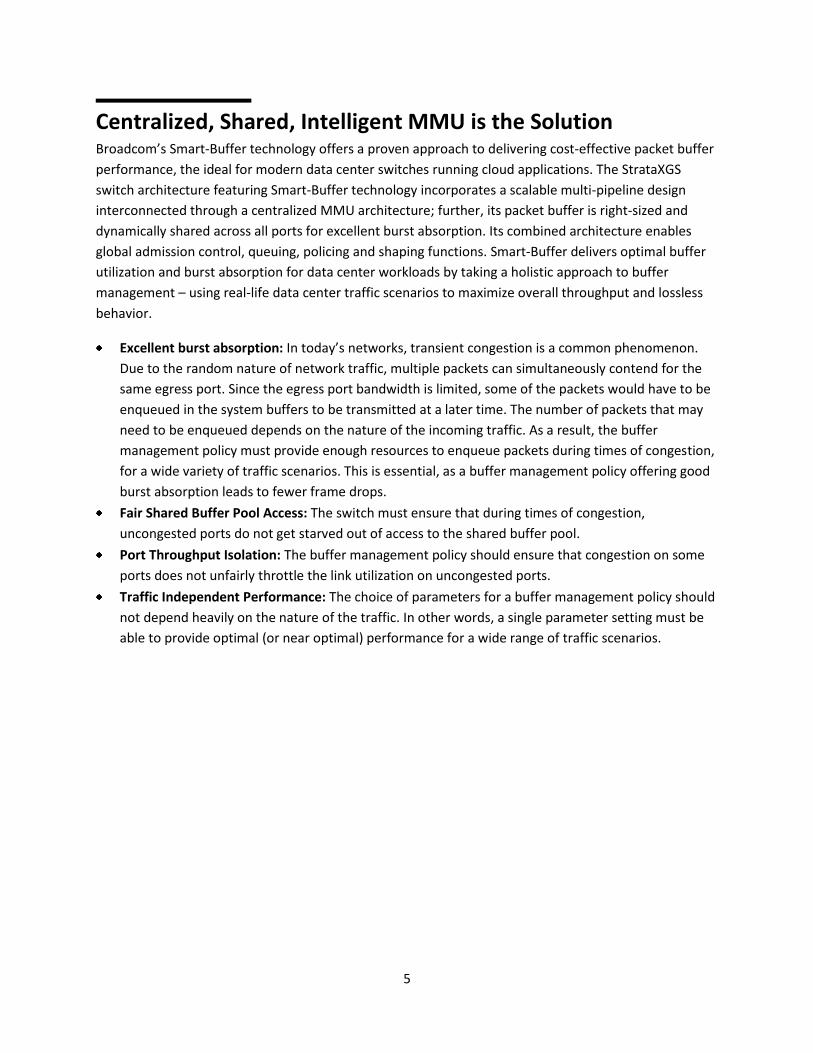
Excellent burst absorption: In today’s networks, transient congestion is a common phenomenon.
Due to the random nature of network traffic, multiple packets can simultaneously contend for the
same egress port. Since the egress port bandwidth is limited, some of the packets would have to be
enqueued in the system buffers to be transmitted at a later time. The number of packets that may
need to be enqueued depends on the nature of the incoming traffic. As a result, the buffer
management policy must provide enough resources to enqueue packets during times of congestion,
for a wide variety of traffic scenarios. This is essential, as a buffer management policy offering good
burst absorption leads to fewer frame drops.
Fair Shared Buffer Pool Access: The switch must ensure that during times of congestion,
uncongested ports do not get starved out of access to the shared buffer pool.
Port Throughput Isolation: The buffer management policy should ensure that congestion on some
ports does not unfairly throttle the link utilization on uncongested ports.
Traffic Independent Performance: The choice of parameters for a buffer management policy should
not depend heavily on the nature of the traffic. In other words, a single parameter setting must be
able to provide optimal (or near optimal) performance for a wide range of traffic scenarios.
6
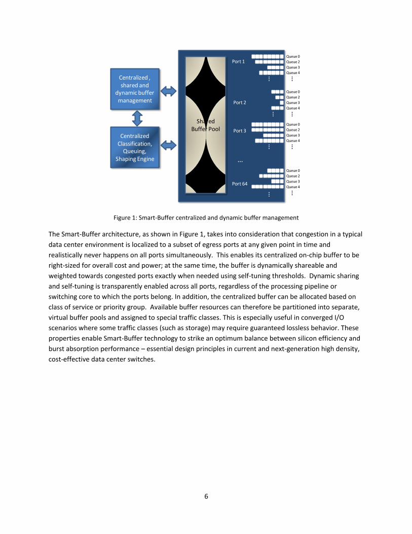
Figure 1: Smart-Buffer centralized and dynamic buffer management
The Smart-Buffer architecture, as shown in Figure 1, takes into consideration that congestion in a typical
data center environment is localized to a subset of egress ports at any given point in time and
realistically never happens on all ports simultaneously. This enables its centralized on-chip buffer to be
right-sized for overall cost and power; at the same time, the buffer is dynamically shareable and
weighted towards congested ports exactly when needed using self-tuning thresholds. Dynamic sharing
and self-tuning is transparently enabled across all ports, regardless of the processing pipeline or
switching core to which the ports belong. In addition, the centralized buffer can be allocated based on
class of service or priority group. Available buffer resources can therefore be partitioned into separate,
virtual buffer pools and assigned to special traffic classes. This is especially useful in converged I/O
scenarios where some traffic classes (such as storage) may require guaranteed lossless behavior. These
properties enable Smart-Buffer technology to strike an optimum balance between silicon efficiency and
burst absorption performance – essential design principles in current and next-generation high density,
cost-effective data center switches.
Centralized Classification,
Queuing, Shaping Engine
Centralized , shared and
dynamic buffer management
……
……
Queue 0
Queue 2
Queue 3
Queue 4…
Queue 0
Queue 2
Queue 3
Queue 4…Queue 0
Queue 2
Queue 3
Queue 4…
Queue 0
Queue 2
Queue 3
Queue 4…
Port 1
Port 3
Port 64
Shared Buffer Pool
…
Port 2
7
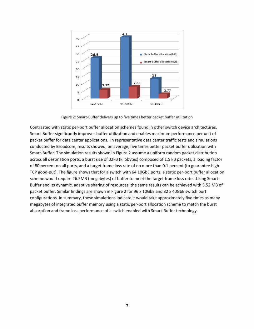
Figure 2: Smart-Buffer delivers up to five times better packet buffer utilization
Contrasted with static per-port buffer allocation schemes found in other switch device architectures,
Smart-Buffer significantly improves buffer utilization and enables maximum performance per unit of
packet buffer for data center applications. In representative data center traffic tests and simulations
conducted by Broadcom, results showed, on average, five times better packet buffer utilization with
Smart-Buffer. The simulation results shown in Figure 2 assume a uniform random packet distribution
across all destination ports, a burst size of 32kB (kilobytes) composed of 1.5 kB packets, a loading factor
of 80 percent on all ports, and a target frame loss rate of no more than 0.1 percent (to guarantee high
TCP good-put). The figure shows that for a switch with 64 10GbE ports, a static per-port buffer allocation
scheme would require 26.5MB (megabytes) of buffer to meet the target frame loss rate. Using Smart-
Buffer and its dynamic, adaptive sharing of resources, the same results can be achieved with 5.52 MB of
packet buffer. Similar findings are shown in Figure 2 for 96 x 10GbE and 32 x 40GbE switch port
configurations. In summary, these simulations indicate it would take approximately five times as many
megabytes of integrated buffer memory using a static per-port allocation scheme to match the burst
absorption and frame loss performance of a switch enabled with Smart-Buffer technology.
Static buffer allocation (MB)
Smart-Buffer allocation (MB)

8
Smart-Buffer Performance Benchmarks The merits of Smart-Buffer technology in modern data center switches are also validated by industry
standard performance metrics. The test results presented in this section were derived from IXIA
automated tests in IETF RFC (Internet Engineering Task Force Request for Comment) standard
configurations, and applied to a Broadcom 64-port 10GbE reference system built on a single StrataXGS
Smart-Buffer enabled switch device. The full suite of tests demonstrates that the Smart-Buffer based 64-
port 10GbE switch delivers consistent 100 percent line rate throughput in 10GbE and 40GbE full-mesh
configurations for minimum to jumbo Ethernet frame sizes. The tests also documented Smart-Buffer’s
very high degree of burst tolerance under congestion and peak loading conditions, with minimal frame
loss.
The benefits of the Smart-Buffer architecture have been illustrated in data center traffic simulations as
well as standard performance benchmarks.
Throughput and Frame Loss Tests
The following figures depict the results of IXIA’s IxAutomate suite of RFC2544 throughput/frame loss
tests and RFC 2889 congestion control tests. The simulations were applied to the 64-port 10GbE
StrataXGS switch device in a full mesh (all ports to all ports) configuration, and subjected to bidirectional
layer 2 (L2) traffic from 64 to 12,280 bytes in size.
Figure 3: RFC2544 Throughput / Frame Loss Test. The Broadcom 64-port 10GbE switch system featuring Smart-
Buffer technology exhibits no drop at 100 percent line rate for all frame sizes.
Figure 3 charts the maximum percentage of line rate throughput at which the device-under-test receives
and forwards frames in a RFC 2544 full-mesh streaming test. The Broadcom 64-port 10GbE switch scores
a consistent 100 percent line rate, with no-drop performance for minimum to jumbo Ethernet frame
sizes.
Packet Size (Bytes)

9
Figure 4: RFC2889 Fully Meshed Throughput test results. The Broadcom 64-port 10GbE switch system featuring
Smart-Buffer exhibits 100 percent line rate performance.
The test results represented in Figure 4 demonstrate that the Broadcom 64-port 10GbE switch is able to
receive and forward all Ethernet frames in a full-mesh, round-robin configuration under maximum load
(when it receives traffic on all 10GbE ports), across all frame sizes, and without incurring any frame loss.
The all-64-byte frame throughput matches the aggregate wire rate of 960 million packets per second
supported by the switch device.
Packet Size (Bytes)
10
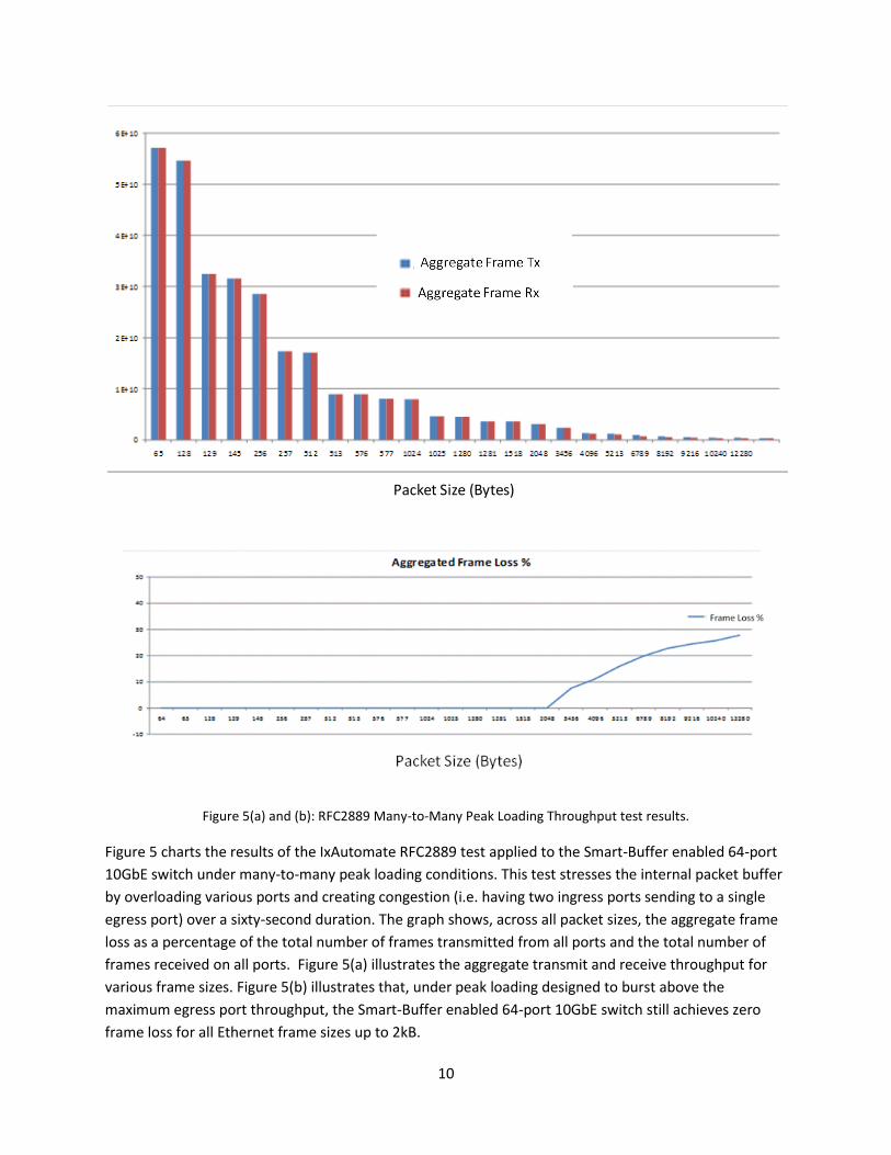
Figure 5(a) and (b): RFC2889 Many-to-Many Peak Loading Throughput test results.
Figure 5 charts the results of the IxAutomate RFC2889 test applied to the Smart-Buffer enabled 64-port
10GbE switch under many-to-many peak loading conditions. This test stresses the internal packet buffer
by overloading various ports and creating congestion (i.e. having two ingress ports sending to a single
egress port) over a sixty-second duration. The graph shows, across all packet sizes, the aggregate frame
loss as a percentage of the total number of frames transmitted from all ports and the total number of
frames received on all ports. Figure 5(a) illustrates the aggregate transmit and receive throughput for
various frame sizes. Figure 5(b) illustrates that, under peak loading designed to burst above the
maximum egress port throughput, the Smart-Buffer enabled 64-port 10GbE switch still achieves zero
frame loss for all Ethernet frame sizes up to 2kB.
Packet Size (Bytes)
11
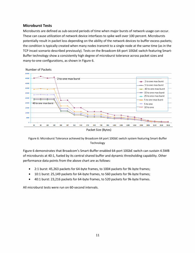
Microburst Tests
Microbursts are defined as sub-second periods of time when major bursts of network usage can occur.
These can cause utilization of network device interfaces to spike well over 100 percent. Microbursts
potentially result in packet loss depending on the ability of the network devices to buffer excess packets;
the condition is typically created when many nodes transmit to a single node at the same time (as in the
TCP incast scenario described previously). Tests on the Broadcom 64-port 10GbE switch featuring Smart-
Buffer technology show a consistently high degree of microburst tolerance across packet sizes and
many-to-one configurations, as shown in Figure 6.
Figure 6: Microburst Tolerance achieved by Broadcom 64 port 10GbE switch system featuring Smart-Buffer
Technology
Figure 6 demonstrates that Broadcom’s Smart-Buffer enabled 64-port 10GbE switch can sustain 4.5MB
of microbursts at 40:1, fueled by its central shared buffer and dynamic thresholding capability. Other
performance data points from the above chart are as follows:
2:1 burst: 45,263 packets for 64-byte frames, to 1004 packets for 9k-byte frames;
10:1 burst: 25,149 packets for 64-byte frames, to 560 packets for 9k-byte frames;
40:1 burst: 23,216 packets for 64-byte frames, to 520 packets for 9k-byte frames.
All microburst tests were run on 60-second intervals.
Packet Size (Bytes)
2 to one max burst
40 to one max burst
Number of Packets
12
Per-Port Static Buffer Architecture Some Ethernet switches may be designed for niche applications where the network is over-provisioned,
and uniform application behavior results in a minimally bursty, near-lossless traffic environment. For
instance, a layer 2 (L2) network serving highly latency-sensitive high performance computing (HPC)
applications would fit this description. Switches targeting such applications can be designed with the
assumption that cut-through forwarding is almost exclusively used, and buffering performance in store-
forward mode is a secondary consideration. A switch silicon solution using this architecture could
therefore optimize for the lowest possible port-to-port latency; enabled by low-touch, cut-through
forwarding logic and small, static, per-port packet buffers with minimal admission control, burst
absorption, and traffic queuing capabilities. The performance burden on the packet processing pipeline
is correspondingly reduced, and the assumption of operating in an over-provisioned lossless
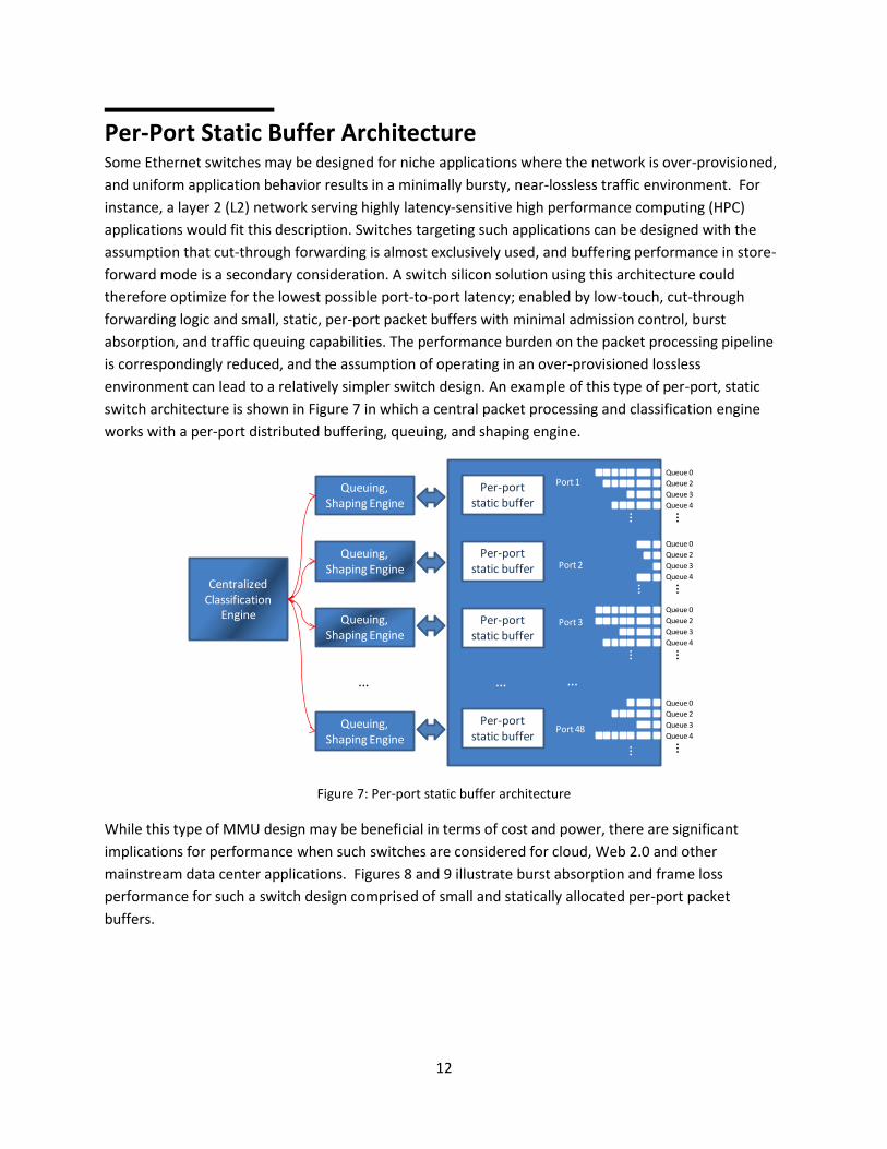
environment can lead to a relatively simpler switch design. An example of this type of per-port, static
switch architecture is shown in Figure 7 in which a central packet processing and classification engine
works with a per-port distributed buffering, queuing, and shaping engine.
Figure 7: Per-port static buffer architecture
While this type of MMU design may be beneficial in terms of cost and power, there are significant
implications for performance when such switches are considered for cloud, Web 2.0 and other
mainstream data center applications. Figures 8 and 9 illustrate burst absorption and frame loss
performance for such a switch design comprised of small and statically allocated per-port packet
buffers.
Centralized Classification
Engine
……
……
Queue 0
Queue 2
Queue 3
Queue 4…
Queue 0
Queue 2
Queue 3
Queue 4…
Queue 0
Queue 2
Queue 3
Queue 4…
Queue 0
Queue 2
Queue 3
Queue 4…
Port 1
Port 3
Port 48
Per-port static buffer
…
Port 2Per-port
static buffer
Per-port static buffer
Per-port static buffer
…
Queuing, Shaping Engine
Queuing, Shaping Engine
Queuing, Shaping Engine
…
Queuing, Shaping Engine
13
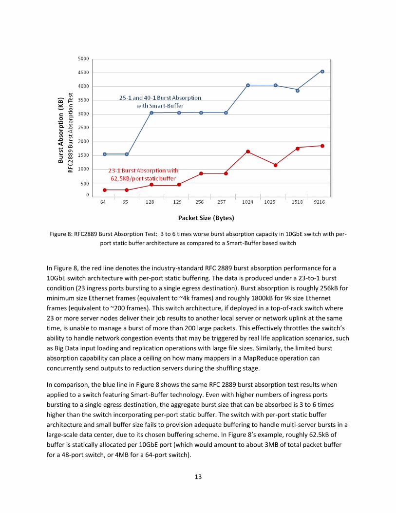
Figure 8: RFC2889 Burst Absorption Test: 3 to 6 times worse burst absorption capacity in 10GbE switch with per-
port static buffer architecture as compared to a Smart-Buffer based switch
In Figure 8, the red line denotes the industry-standard RFC 2889 burst absorption performance for a
10GbE switch architecture with per-port static buffering. The data is produced under a 23-to-1 burst
condition (23 ingress ports bursting to a single egress destination). Burst absorption is roughly 256kB for
minimum size Ethernet frames (equivalent to ~4k frames) and roughly 1800kB for 9k size Ethernet
frames (equivalent to ~200 frames). This switch architecture, if deployed in a top-of-rack switch where
23 or more server nodes deliver their job results to another local server or network uplink at the same
time, is unable to manage a burst of more than 200 large packets. This effectively throttles the switch’s
ability to handle network congestion events that may be triggered by real life application scenarios, such
as Big Data input loading and replication operations with large file sizes. Similarly, the limited burst
absorption capability can place a ceiling on how many mappers in a MapReduce operation can
concurrently send outputs to reduction servers during the shuffling stage.
In comparison, the blue line in Figure 8 shows the same RFC 2889 burst absorption test results when
applied to a switch featuring Smart-Buffer technology. Even with higher numbers of ingress ports
bursting to a single egress destination, the aggregate burst size that can be absorbed is 3 to 6 times
higher than the switch incorporating per-port static buffer. The switch with per-port static buffer
architecture and small buffer size fails to provision adequate buffering to handle multi-server bursts in a
large-scale data center, due to its chosen buffering scheme. In Figure 8’s example, roughly 62.5kB of
buffer is statically allocated per 10GbE port (which would amount to about 3MB of total packet buffer
for a 48-port switch, or 4MB for a 64-port switch).

14
Figure 9: RFC2889 Partial Mesh Packet Loss Test: Switch with per-port static buffer architecture is susceptible to up
to 4.5 percent frame loss
Figure 9 shows the results of the industry standard RFC 2889 Partial Mesh Packet Loss Test conducted
on the same switch with per-port static buffer architecture. With 62.5kB of static packet buffer
allocation per port, the switch exhibits significant lossiness above 256-byte frame sizes; up to 4.5
percent of packets are dropped. This is a prohibitively high level of network loss for mainstream data
center workloads. Frame loss drives TCP retransmission of packets, which significantly increases the
latency experienced by the data center application. In addition, certain protocols such as Fiber-Channel-
over-Ethernet (FCoE) do not provide retransmission capability and therefore cannot tolerate any packet
loss whatsoever. Even with Priority Flow Control enabled, typical frame loss targets should be below 1
percent in order to avoid excessive server backpressure that can dwindle application performance to
unacceptable levels.
In contrast to the switch incorporating a per-port static buffer architecture, the blue line in Figure 9
shows that a switch using Smart-Buffer technology can eliminate frame loss under the partial mesh test.
The data illustrates its ability to maximize application performance under bursty traffic conditions.
15
Summary Data center workloads demand high throughput and robust, consistent performance from Ethernet
switches; these performance features are required in order to handle characteristic traffic patterns in
their networks. Cloud-centric workloads such as Hadoop/MapReduce require network switches with
excellent burst absorption capabilities in order to avoid TCP incast problems. With the current transition
of server interfaces from GbE to 10GbE performance, demands in server access infrastructure
necessitate highly integrated network switch devices that utilize multiple switching cores and pipelines.
At the same time, cost and power metrics in the cloud drive the need for fully integrated buffers and
sophistication in switch MMU design. Smart-Buffer, part of Broadcom’s SmartSwitch technology series,
was developed in response to these essential industry needs. An innovative, proven switch device
technology, Smart-Buffer implements a centralized, fully shareable, dynamically allocated, and adaptive
packet memory management architecture. This sophisticated technology offers an alternative to design
approaches based on statically allocated, per-port packet buffering schemes that can lead to
prohibitively poor application performance under typical data center traffic loads. Broadcom’s high
density 10GbE switches featuring Smart-Buffer technology demonstrate excellent throughput and a high
degree of burst tolerance, with zero frame loss for network congestion events found in the data center.
Cloud network operators are already facing daunting challenges in scaling their network infrastructure
to tomorrow’s workloads; an understanding of the underlying switch architectures and the tradeoffs
they require between performance, cost, and power can help operators select the appropriate switching
equipment for their applications.