broadgate phase 11 · design concept exterior grid frame parabolic arch bridge stone pier supports...
TRANSCRIPT

Broa
dgat
e Ph
ase
11Daniel Nowell
2

Srinivasa “Hal” IyengarSOMIn
trod
uctio
ns
Skidmore, Owings & Merrill have had a long legacy of structurally significant buildings: The Sears Tower with its bundled tubes, and The John Hancock Center with it’s prominent X-bracing. Broadgate Phase 11 - Exchange House falls right in line with this structurally emphasized approach to architecture. Srinivasa “Hal” Iyengar worked alongside famous structural engineer Fazlur Kahn to develop the structural systems for both The Sears Tower and The John Hancock Center, but when pressed to cite the most innovative building of his career, Hal, a renowned structural engineer himself, will tell you about Broadgate Phase 11 - Exchange House. The Exchange House is only one building in a large development named Broadgate in London, England. SOM served as both the architect and engineer for the Exchange House. The firm regularly takes this dual role, and it comes across in their designs. 6
5 2
7
Des
ign
Con
cept
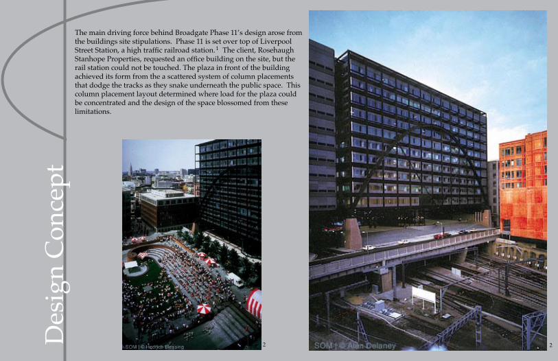
The main driving force behind Broadgate Phase 11’s design arose from the buildings site stipulations. Phase 11 is set over top of Liverpool Street Station, a high traffic railroad station. The client, Rosehaugh Stanhope Properties, requested an office building on the site, but the rail station could not be touched. The plaza in front of the building achieved its form from the a scattered system of column placements that dodge the tracks as they snake underneath the public space. This column placement layout determined where load for the plaza could be concentrated and the design of the space blossomed from these limitations.
1
22

Des
ign
Con
cept Exterior Grid Frame
Parabolic Arch Bridge
Stone Pier Supports
Concrete Deck
Trains
The building itself could not use this same method of random column placement. To regulate office space in the 10 storey building, a regular structural grid was needed. But how could a regular grid be employed when none of the columns could touch the ground? The geniuses at SOM conjured up three different systems that could support the building over the 78 meter clear span: “An X-braced truss system, a 10 storey catenary suspension system, and a parabolic arch system.” Both the X-braced truss system and the catenary suspension system revealed themselves as inefficient and overly expensive. However, the parabolic arch system could be constructed conventionally and use less material to get the job done. The plan was to design a bridge that could withstand the constant dead load of a 10 storey office building on top of it as well as fluctuating live loads due to human traffic within the office building. The decision was made to expose all of the structure in its purely functional state to respond to the history and nature of the railway that passed below the building.
6

Plan
s/El
evat
ions
2

Fram
ing
The floor trusses, represented in red, span across the four arches, represented in blue, tying them together. The arches carry the load down to 8 masonry piers, represented in green, to contact the earth.

Load
s & S
tres
ses
Reactions
Loads
Gravity loads from the top 3 floors, which are supported by each other in compression, are transferred directly to the parabolic arch through the regular 6 meter structural grid of the office building. The compres-sion forces are spread across the arch, which crowns at the top of the 7th storey. Diagonal rods are attached to the underside of the arch. They op-erate in tension to provide additional support for the bridge’s horizontal span. If one could imagine a vertical support in the middle of the arch, it may be easier to understand the diagonal members’ role in supporting the load because one could draw the stress pattern down the vertical member , up the two diagonals and then down the arch to the supports. However, there is no need for a vertical member in the center of the arch because all of the work is distributed amongst the triangulated forms created by the diagonals. In this way, the simple arch is allowed to act as a truss. Loads are dispersed down the arch truss and transferred to the 8 masonry piers, which are the only contact that Broadgate Phase 11 has with the ground. These piers splay out from the connection with the arch to spread the load as much as possible on contact with the ground. At the same time the diagonal members are pulling up the base of the arch truss so that the first 7 floors are completely hung from the arch.
2

Fire
Eng
inee
ring
Fire and life safety is normally a portion of the design process that gets neglected and ultimately thrown in to meet codes at the last minute. However, it is fire and life safety that are prominently displayed on Broadgate Phase 11. The structure of this building is purely steel. Overall 7000 tons of steel is in-corporated into the structure of Broadgate Phase 11 - Exchange House. With all of that steel, a mess of fire proof coating is required. Conventional means are used on the hidden interior structure, but any piece of exposed steel is covered with a deceiving paint job. New at the time of Broadgate’s construc-tion, intumescent paint is employed to show off the structure while keeping it safe. Its deceiving because until the paint comes in contact with extremely high temperatures, it looks just like regular paint. Once the heat rises though, the intumes-cent paint puffs up to create a thick layer of dense insulation around the structural member.
Since all of the structure was moved to the exterior of the building, it only made sense to hang the stairs off of the exteri-or structure too. Where as most exterior fire stair applications point toward a deficiency in a building’s design, Broadgate Phase 11 incorporates its fire stairs into the appeal of the exposed structure. They extend from the buildings body with graceful majesty, tied back to the frame by a series of tension rods. All of the weight developed by the stairs is transferred back into the frame where it can be dealt with safely.
2
Con
nect
ions
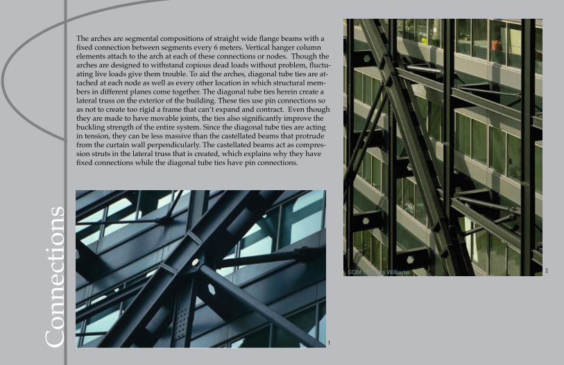
The arches are segmental compositions of straight wide flange beams with a fixed connection between segments every 6 meters. Vertical hanger column elements attach to the arch at each of these connections or nodes. Though the arches are designed to withstand copious dead loads without problem, fluctu-ating live loads give them trouble. To aid the arches, diagonal tube ties are at-tached at each node as well as every other location in which structural mem-bers in different planes come together. The diagonal tube ties herein create a lateral truss on the exterior of the building. These ties use pin connections so as not to create too rigid a frame that can’t expand and contract. Even though they are made to have movable joints, the ties also significantly improve the buckling strength of the entire system. Since the diagonal tube ties are acting in tension, they can be less massive than the castellated beams that protrude from the curtain wall perpendicularly. The castellated beams act as compres-sion struts in the lateral truss that is created, which explains why they have fixed connections while the diagonal tube ties have pin connections.
2
1

Con
nect
ions
The ties brace the arches horizontal thrust so that only vertical reactions are to be dealt with at the bearing points. The arch shares a semi-fixed connection with the masonry pier through a bearing pad. However, a pin connection is used with the base horizontal beam at that same location to provide rotational relief. This connection allows for less lateral strain and provides a comfortable range of motion for changing gravity loads as well as temperature fluctuations.
22

Con
stru
ctio
n Four arches, two concealed on the interior, and two promptly displayed on the exterior, make up the support system for the entire building. The three bays created by the arches are spanned by composite floor trusses, which provide lateral bracing. Along both ends of the building perpendicular to the arches, an exposed vertical truss in the middle bay connects with the floor diaphragm to resist wind loads on the broad building. It also provides out of plane stability to the arches. All of the exterior exposed structure is offset from the 78 meter by 52 meter rectangular plan of the building by 2 meters. Due to the use of such strict modularity, all of these structural units came to the site pre-fabricated. This allowed for savings in material costs and labor, not to mention time. An all glass and steel curtain-wall is hung from the exposed frame to keep a constant backdrop for the exposed structure.
34

6
Cur
tain
Wal
l
6
6

Foot
note
s 1. “Bridge Form.” Corus in Construction. 29 July 2008 <http://www.corusconstruction.com/en/reference/teaching_resources/architectural_studio_reference/design/bridges/bridge_form/>.
2. “Broadgate - Exchange House.” SOM.com. 28 July 2008 <http://www.som.com/content.cfm/broadgate_exchange_house>.
3. Broadgate [Image of Broadgate Exchange House with scaffolding up the front of it.]. Digital image. Victor Buyck Steel Construction. 30 July 2008 <http://www.buyck.be/broadgate.htm>.
4. Bussel, Abby. SOM Evolutions: Recent Work of Skidmore, Owings & Merrill. Basel: Birkhauser, 2000.
5. Dobney, Stephen, ed. The Master Arcchitect Series Skidmore, Owings & Merrill: Selected and Current Works. Mulgrave: The Images Group Pty Ltd, 1995.
6. Sarrach, Richard. 22 June 2008. SOM-BroadGate-Exchange House, Pratt Architectural Design Studios, NYC. Flickr. 24 June 2008. 26 Aug. 2008 <http://flickr.com/photos/8507144@n08/2609098558/>.
7. Weger, Tonya. “Hal Iyengar’s three decades at SOM: From Chicago’s Sears Tower to Spain’s Guggenheim Museum.” Modern Steel Con struction May 2000.

Wor
ks C
ited
“Bridge Form.” Corus in Construction. 29 July 2008 <http://www.corusconstruction.com/en/reference/teaching_resources/architectural_studio_reference/design/bridges/bridge_form/>.
“Broadgate - Exchange House.” SOM.com. 28 July 2008 <http://www.som.com/content.cfm/broadgate_exchange_house>.
Broadgate [Image of Broadgate Exchange House with scaffolding up the front of it.]. Digital image. Victor Buyck Steel Construction. 30 July 2008 <http://www.buyck.be/broadgate.htm>.
Bussel, Abby. SOM Evolutions: Recent Work of Skidmore, Owings & Merrill. Basel: Birkhauser, 2000.
Dobney, Stephen, ed. The Master Arcchitect Series Skidmore, Owings & Merrill: Selected and Current Works. Mulgrave: The Images Group Pty Ltd, 1995.
Iyengar, Hal, William Baker, and R. C. Sinn. “Broadgate Exchange House: Structural System.” The Structural Engineer 71 (1993): 149-59.
Sarrach, Richard. 22 June 2008. SOM-BroadGate-Exchange House, Pratt Architectural Design Studios, NYC. Flickr. 24 June 2008. 26 Aug. 2008 <http://flickr.com/photos/8507144@n08/2609098558/>.
Weger, Tonya. “Hal Iyengar’s three decades at SOM: From Chicago’s Sears Tower to Spain’s Guggenheim Museum.” Modern Steel Con struction May 2000.