brookfield digital viscometer operating instructions...
TRANSCRIPT
BROOKFIELD DIGITAL VISCOMETER
MODELDV-1+
Operating Instructions
Manual No. M/92-021-A-892
BROOKFIELD ENGINEERING LABORATORIES, INC. 240 Cushing Street, Stoughton, MA 02072 USA
Phone: 617-344-4310/4313 800-628-8139 (U.S. except MA); Fax: 617-344-7141 Telex: 924497 BRENLAB STOU (Western Union); 200195 BEL (RCA)
TABLE OF CONTENTS
L J:N'TRODUCfiON ......................................................................... 3 1 Com:p<>nents ............................................................................ 3 2 Utilities ................................................................................... 4 3 Specifications ......................................................................... 4 4 Set-Up ............................. ; ....................................................... 4 S Key Functions ........................................................................ 5
ll. GETTJ:N'G STARTED .................................................................. 6 1 Autozero ................................................................................. 6 2 Spindle Selection .................................................................... 6 3 Speed Selection & Setting ...................................................... 7 4 Autorange Operation .............................................................. 9 S Out of Range Operation ....................................................... 10
Appendix A Cone/Plate Viscometer Set-Up .................................. 11 Appendix B - Viscosity Ranges ........................................................ 16 Appendix C - Variables in Viscosity Measurements ........................ 18 Appendix D Spindle and Model Codes .......................................... 20 Appendix E - Calibration Procedures ............................................... 22 Appendix F - Special Speed Sets ..................................................... 26 Appendix G - Communications ........................................................ 27 Appendix H - Fault Diagnosis and Troubleshooting ........................ 28 Appendix I - Warranty Repair and Service ..................................... 31
I. INTRODUCTION
The Brookfield DV-1+ Viscometer measures fluid viscosity at given shear rates. Viscosity is a measure of a fluid's resistance to flow. You will find a detailed description of the mathematics of viscosity in the Brookfield publication "More Solutions to Sticky Problems" a copy of which was included with your DV -I+. The principle of operation of the DV -I+ is to drive a spindle (which is immersed in the test fluid) through a calibrated spring. The viscous drag of the fluid against the spindle is measured by the spring deflection. Spring deflection is measured with a rotary transducer. The measuring range of a D V ·I+ (in centipoise) is determined by the rotational speed of the spindle, the size and shape of the spindle, the container the spindle is rotating in, and the full scale torque of the calibrated spring.
There are four basic spring torque series offered by Brookfield:
Model LVDV-1+ RVDV-1+ HADV-1+ HBDV-1+
Sprip~ TOTQ.ue <Dyne-em) 673.7
7,187.0 14,374.0 57,496.0
The higher the torque calibration, the higher the measurement range. The viscosity measurement range for each torque calibration may be found in Appendix B.
All units of measurement are displayed according to the CGS system.
1. Viscosity appears in units of centipoise (shown as "cP" on the DV-1+ Viscometer display).
2. Torque appears in units of Dyne-centimeters (shown as percent"%" on the DV-1+ Viscometer display).
The equivalent units of measurement in the Sl system are calculated using the following conversions:
Sl ~ Viscosity: Torque:
1 mPa•s 1 Newton-m
= 1 cP = w1 dyne-em
Ll COMPONENTS
1) DV-1+ Viscometer 2) Model A Laboratory Stand 3) Spindle Set with Case (4 spindles for LVDV-1+; 7 Spindles for RV, HA and HBDV-1+).
For Cone/Plate versions: a spindle wrench, one cone spindle and a sample cup (Part No. CP-44Y) replace the spindle set.
4) Power cord 5) Guard Leg (LVDV-1+ and RVDV-1+ only) 6) Carrying Case.
Please check to be sure that you have received all components, and that there is no damage. H you are missing any parts, please notify Brookfield Engineering or your local Brookfield agent immediately. Any shipping damage must be reported to the carrier.
- 3-
12 Utilities
Input Voltage: Input Frequency: Power Consumption:
Power Cord Color Code:
Hot (live) Neutral Ground (earth)
13 Specifications
115 VACor230VAC 50/fiJ Hz Less than 20 W A TIS
United States Black White Green
Outside United States Brown Blue GreenlY ellow
Speeds: LVDV-1+: 0.0, 0.3, 0.6, 1.5, 3, 6, 12, 30, fl.), 0.0, 0.5, 1, 2, 2.5, 4, 5, 10, 20, 50, 100
Weight:
RV/HAIHBDV-1+:
Gross Weight Net Weight Carton Volume
0.0, 0.5, 1, 2, 2.5, 4, 5, 10, 20, 50, 100, 0.0, 0.3, 0.6, 1.5, 3, 6, 12, 30, fl.)
20 lb 17 lb 1.65 cu ft
9 kg 7.7 kg
0.05 m3
Analog Torque Output: 0- 1 Volt DC (0- 100% Torque)
14 Set-Up
1) Place the upright rod into the base. Refer to assembly instructions (82-0330) supplied with Model A Laboratory Stand. The rack gear and clamp assembly should face the front of the base. The upright rod is held in place with the jam nut which is attached from the bottom of the base. Tighten this nut with a suitable wrench (spanner).
2) Insert the mounting handle on the back of the DV -I+ Viscometer into the hole on the clamp assembly.
3) Tighten the VS-24Y clamp screw.
4) The viscometer must be leveled. The level is adjusted using the three leveling screws on the base. Adjust so that the bubble level on top of the DV -I+ is centered within the circle.
5) Make sure that the AC power switch at the rear of the DV -I+ is in the OFF position. Connect the power cord to the socket on the back panel of the instrument and plug it into the appropriate AC line. The AC input voltage and frequency must be within the appropriate range as shown on the name plate of the viscometer.
NOTE: The DV-1+ must be earth grounded to ensure against electronic failure!!
6) For Cone/Plate models, refer to Appendix A.
-4-
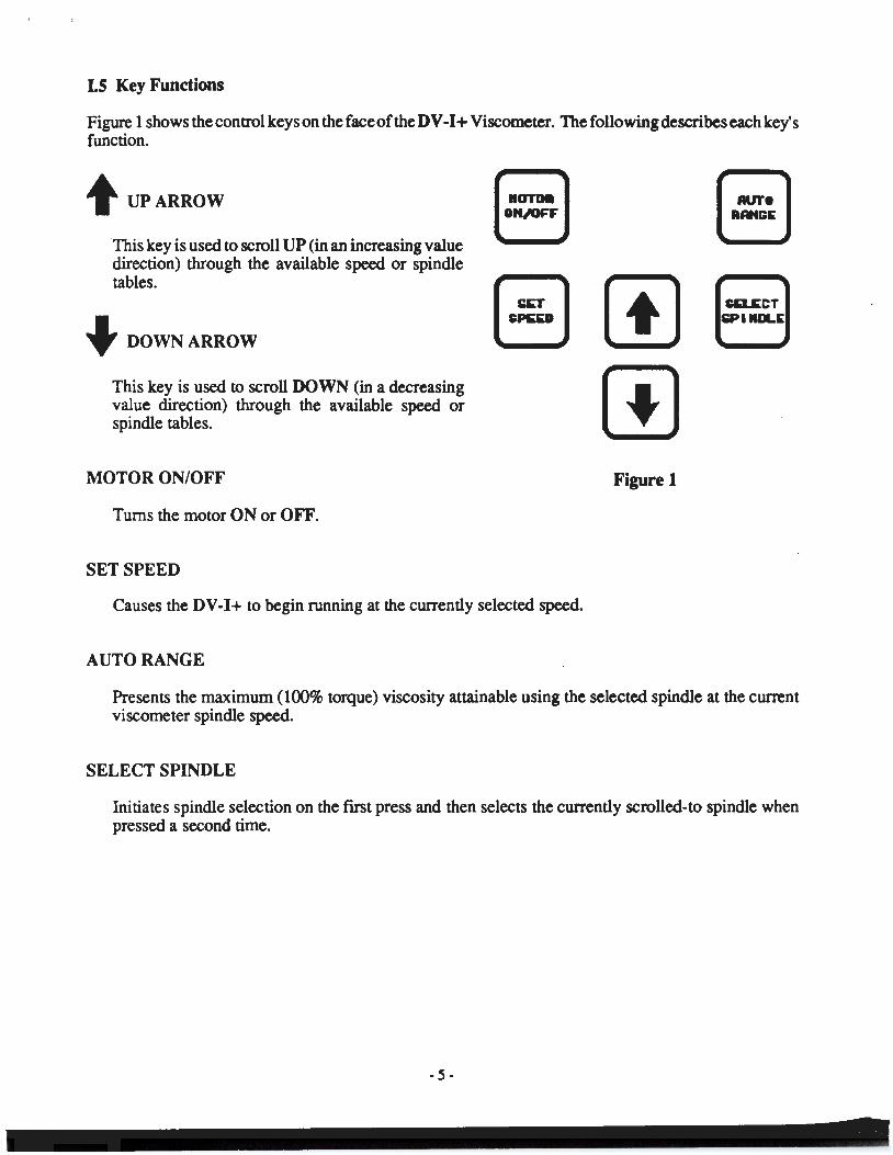
1.5 Key Functions
Figure 1 shows the control keys on the face of the DV -I+ Viscometer. The following describes each key's function.
t UPARROW
This key is used to scroll UP (in an increasing value direction) through the available speed or spindle tables.
+ DOWNARROW
This key is used to scroll DOWN (in a decreasing value direction) through the available speed or spindle tables.
MOTOR ON/OFF
Turns the motor ON or OFF.
SET SPEED
r:::1 t:::J r::l L:::J
Causes the DV-1+ to begin running at the currently selected speed.
AUTO RANGE
Figure 1
C~CT SiPIIIDLIE
Presents the maximum (100% torque) viscosity attainable using the selected spindle at the current viscometer spindle speed.
SELECT SPINDLE
Initiates spindle selection on the fli'St press and then selects the currently scrolled-to spindle when pressed a second time.
- 5-
ll GETTING STARTED
ll.l Autozero
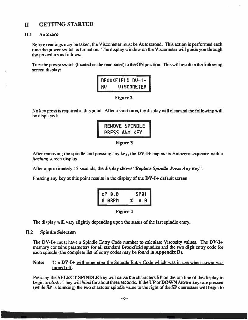
Before readings may be taken, the Viscometer must be Autozeroed. This action is performed each time the power switch is turned on. The display window on the Viscometer will guide you through the procedure as follows:
Turn the power switch (located on the rear panel) to the ON position. This will result in the following screen display:
BROOKFIELD DU-1+ RU UISCOMETER
Figure 2
No key press is required at this point. After a short time, the display will clear and the following will be displayed:
REMOVE SPINDLE PRESS ANY KEY
Figure 3
After removing the spindle and pressing any key, the DV-1+ begins its Autozero sequence with a flashing screen display.
After approximately 15 seconds, the display shows "Replace Spindk Pnss Any Key".
Pressing any key at this point results in the display of the DV -I+ default screen:
cP 9.9 9.9RPM
SP91 1 e.e
Figure 4
The display will vary slightly depending upon the status of the last spindle entry.
ll.2 Spindle Selection
The DV-1+ must have a Spindle Entry Code number to calculate Viscosity values. The DV-1+ memory contains parameters for all standard Brookfield spindles and the two digit entry code for each spindle (the complete list of entry codes may be found in Appendix D).
Note: The DV-1+ will remember the Spindle Entry Code which was in use when power was turned off.
Pressing the SELECT SPINDLE key will cause the characters SP on the top line of the display to begin to blink. They will blink for about three seconds. If the UP or DOWN Arrow keys are pressed (while SP is blinking) the two character spindle value to the right of the SP characters will begin to
-6-
begin to blink. They will blink for about three seconds. If the UP or DOWN Arrow keys are pressed (while SP is blinking) the two character spindle value to the right of the SP characters will begin to change (in either an increasing or decreasing direction depending upon which Arrow key is pressed) for each press of the key. If the Arrow key is pressed and held, the display will scroll through the spindle codes for as long as the Arrow key is depressed. When it reaches the last item in the list (either at the top or bottom of the list) the spindle code displayed will "roll-over" to either the first or last spindle code and the scroll action will continue.
When the desired spindle code is displayed, release the Arrow key to halt further scrolling. Press the SELECT SPINDLE key once again. This will cause the SP characters to cease blinking and the new spindle code will be accepted for use in viscometer calculations.
Note: You have approximately three seconds in which to press the SELECT SPINDLE key before the blinking stops. If you fail to press the SELECT SPINDLE key before the blinking stops you will have to repeat the above steps and re-select the desired spindle.
The DV-I+ will begin to calculate using the new spindle parameters as soon as the SELECT SPINDLE key is pressed the second time.
The DV -I+ may also be programmed at Brookfield Engineering for "special" user spindles. These "special" spindles will show up on the spindle scroll list starting with the designation "AA" and continuing through "AZ". Contact Brookfield Engineering regarding your needs for special spindles.
11.3 Speed Selection & Setting
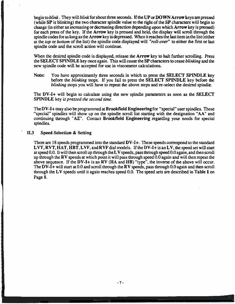
There are 18 speeds programmed into the standard DV-I+. These speeds correspond to the standard L VT, RVT, HAT, HBT, L VF, and RVF dial models. If the DV -I+ is an LV, the speed set will start at speed 0.0. It will then scroll up through the LV speeds, pass through speed 0.0 again, and then scroll up through the RV speeds at which point it will pass through speed 0.0 again and will then repeat the above sequence. If the DV-I+ is an RV (HA and HB) "type", the inverse of the above will occur. The DV -I+ will stan at 0.0 and scroll through the RV speeds, pass through 0.0 again and then scroll through the LV speeds until it again reaches speed 0.0. The speed sets are described in Table 1 on Page 8.
-7-
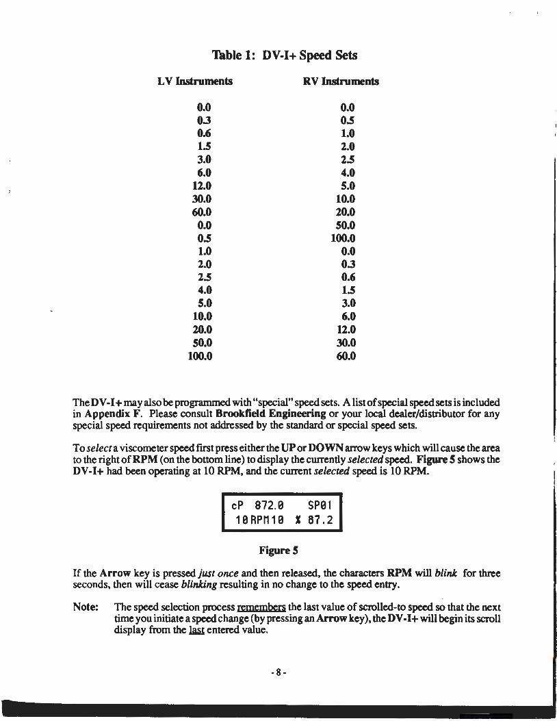
Table 1: DV-1+ Speed Sets
LV Instruments
0.0 0.3 0.6 1.5 3.0 6.0
12.0 30.0 60.0 0.0 0.5 1.0 2.0 2.5 4.0 5.0
10.0 20.0 50.0
100.0
RV Instruments
0.0 0.5 1.0 2.0 2.5 4.0 5.0
10.0 20.0 50.0
100.0 0.0 0.3 0.6 1.5 3.0 6.0
12.0 30.0 60.0
The D V-I+ may also be programmed with "special" speed sets. A list of special speed sets is included in Appendix F. Please consult Brookfield Engineering or your local dealer/distributor for any special speed requirements not addressed by the standard or special speed sets.
To select a viscometer speed first press either the UP or DOWN arrow keys which will cause the area to the right of RPM (on the bottom line) to display the currently selected speed. Figure 5 shows the DV-I+ had been operating at 10 RPM, and the current selected speed is 10 RPM.
cP 872. B SPB 1 1 B RPM 1 B J 67. 2
Figure 5
If the Arrow key is pressed just once and then released, the characters RPM will blink for three seconds, then will cease blinking resulting in no change to the speed entry.
Note: The speed selection process remembers the last value of scrolled-to speed so that the next time you initiate a speed change (by pressing an Arrow key), the DV -I+ will begin its scroll display from the ~ entered value.
-8-
..
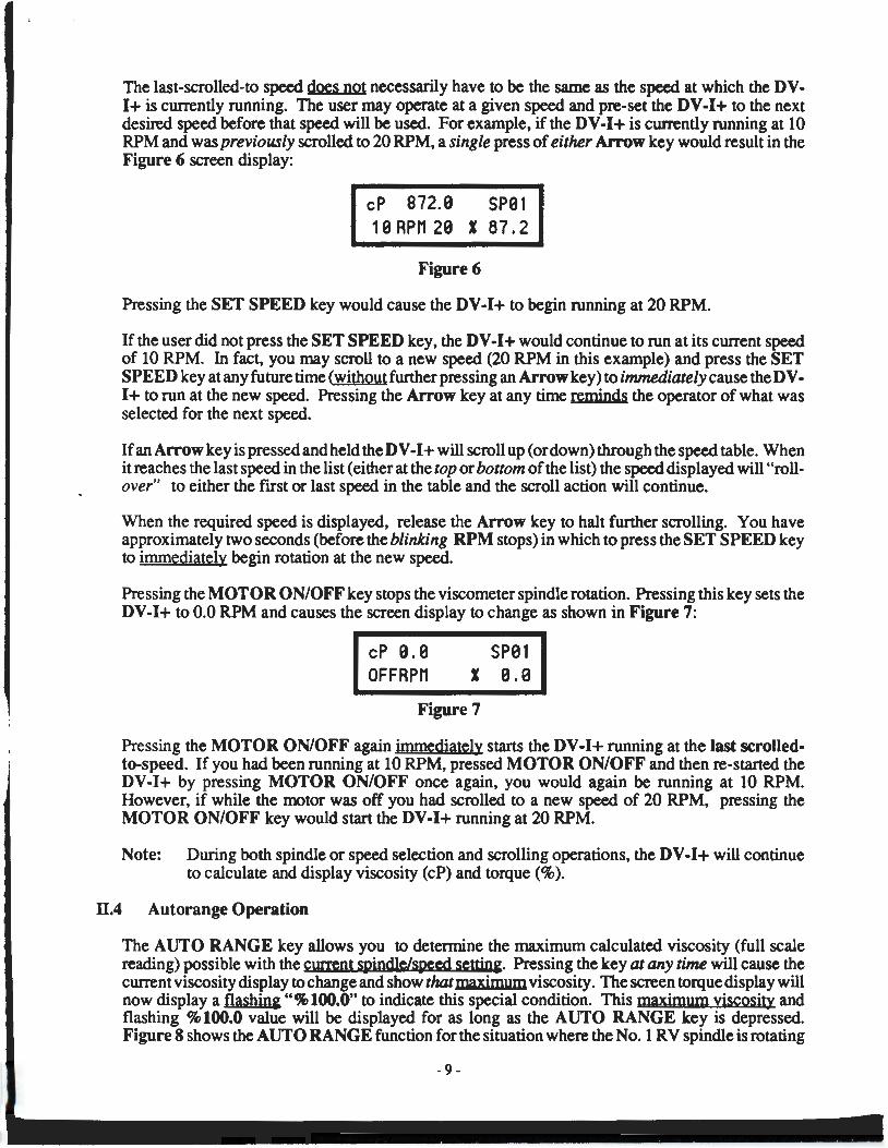
The last-scrolled-to speed does not necessarily have to be the same as the speed at which the DVI+ is currently running. The user may operate at a given speed and pre-set the DV-I+ to the next desired speed before that speed will be used. For example, if the DV-I+ is cUJTently running at 10 RPM and was previously scrolled to 20 RPM, a single press of either Arrow key would result in the Figure 6 screen display:
cP 872.9 SPB1 1 9 RPM 29 I 87. 2
Figure 6
Pressing the SET SPEED key would cause the DV-I+ to begin running at 20 RPM.
If the user did not press the SET SPEED key, the D V-I+ would continue to run at its current speed of 10 RPM. In fact, you may scroll to a new speed (20 RPM in this example) and press the SET SPEED key at any future time (without further pressing an Arrow key) to immediately cause the D VI+ to run at the new speed. Pressing the Arrow key at any time reminds the operator of what was selected for the next speed.
If an Arrow key is pressed and held the DV-I+ will scroll up (or down) through the speed table. When it reaches the last speed in the list (either at the top or bottom of the list) the speed displayed will "roll-· over" to either the first or last speed in the table and the scroll action will continue.
When the required speed is displayed, release the Arrow key to halt further scrolling. You have approximately two seconds (before the blinking RPM stops) in which to press the SET SPEED key to immediately begin rotation at the new speed.
Pressing the MOTOR ON/OFF key stops the viscometer spindle rotation. Pressing this key sets the DV-I+ to 0.0 RPM and causes the screen display to change as shown in Figure 7:
cP 9.9 OFF RPM
SP91 I 9.9
Figure 7
Pressing the MOTOR ON/OFF again immediately starts the DV-I+ running at the last scrolledto-speed. If you had been running at 10 RPM, pressed MOTOR ON/OFF and then re-started the DV-1+ by pressing MOTOR ON/OFF once again, you would again be running at 10 RPM. However, if while the motor was off you had scrolled to a new speed of 20 RPM, pressing the MOTOR ON/OFF key would start the DV-I+ running at 20 RPM.
Note: During both spindle or speed selection and scrolling operations, the DV-I+ will continue to calculate and display viscosity (cP) and torque(%).
11.4 Autorange Operation
The AUTO RANGE key allows you to determine the maximum calculated viscosity (full scale reading) possible with the current mindle!speed settin&. Pressing the key at any time will cause the current viscosity display to change and show that maximum viscosity. The screen torque display will now display a flashin& "%100.0" to indicate this special condition. This maximum viscosity and flashing %100.0 value will be displayed for as long as the AUTO RANGE key is depressed. Figure 8 shows the AUTO RANGE function for the situation where the No.1 RV spindle is rotating
-9-
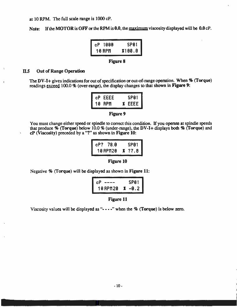
at 10 RPM. The full scale range is 1000 cP.
Note: H the MOTOR is OFF or the RPM is 0.0, the maximum viscosity displayed will be 0.0 cP.
II.S Out of Range Operation
cP 1999 19 RPM
SP91 119010
Figure 8
The DV -I+ gives indications for out of specification or out-of-range operation. When % (Torque) readings exceed 100.0% (over-range), the display changes to that shown in Figure 9:
cP EEEE 19 RPM
SP91 I EEEE
Figure 9
You must change either speed or spindle to correct this condition. H you operate at spindle speeds that produce% (Torque) below 10.0% (under-range), the DV-1+ displays both% (Torque) and cP (Viscosity) preceded by a"?" as shown in Figure 10:
cP? 78.9 SP9 1 1 0 RPM29 1 ?7 I a
Figure 10
Negative % (Torque) will be displayed as shown in Figure 11:
cP ---- SP01 1 0 RPM 20 1 -9 I 2
Figure 11
Viscosity values will be displayed as"····" when the% (Torque) is below zero.
APPENDIX A - Cone/Plate Viscometer Set-Up
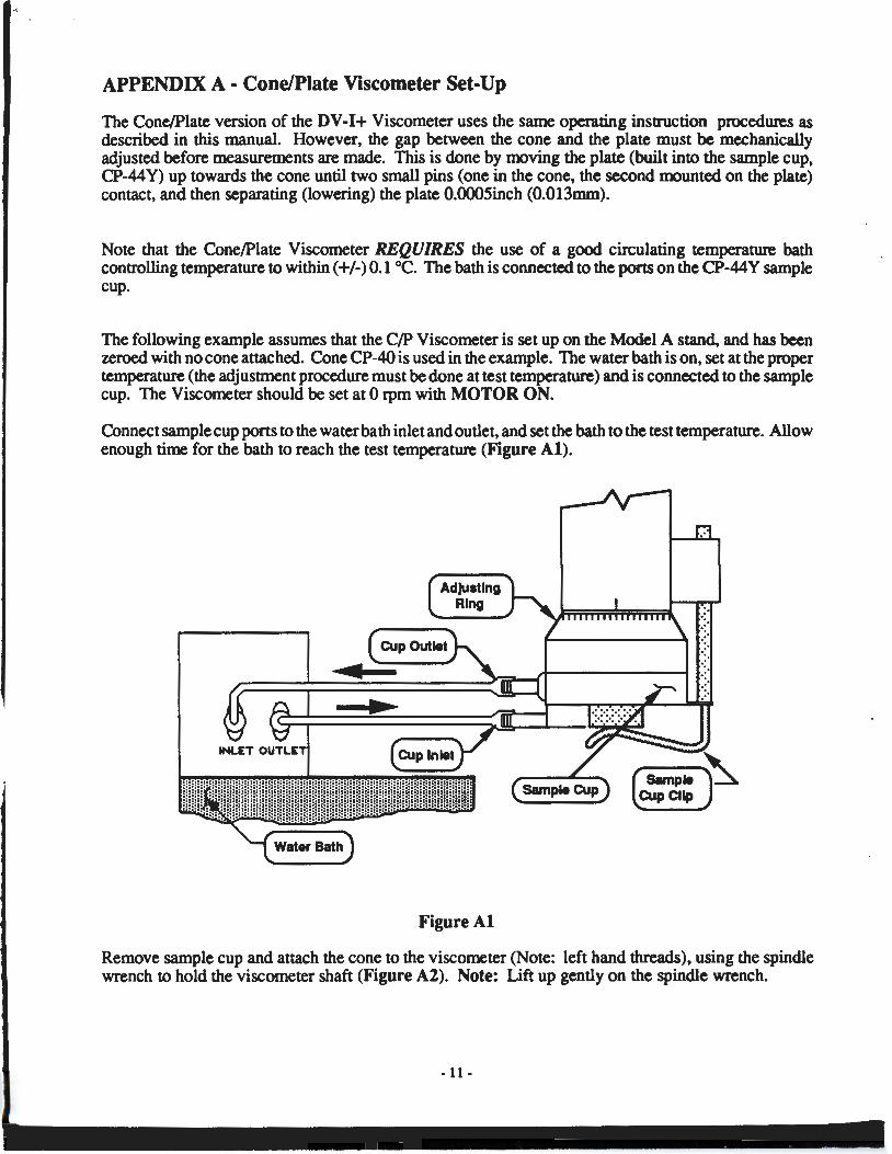
The Cone/Plate version of the DV-1+ Viscometer uses the same operating instruction procedures as described in this manual. However, the gap between the cone and the plate must be mechanically adjusted before measurements are made. This is done by moving the plate (built into the sample cup, CP-44Y) up towards the cone until two small pins (one in the cone, the second mounted on the plate) contact, and then separating (lowering) the plate 0.0005inch (0.013mm).
Note that the Cone/Plate Viscometer REQUIRES the use of a good circulating temperature bath controlling temperature to within (+I-) 0.1 °C. The bath is connected to the ports on the CP-44 Y sample cup.
The following example assumes that the C/P Viscometer is set up on the Model A stand, and has been zeroed with no cone attached. Cone CP-40 is used in the example. The water bath is on, set at the proper temperature (the adjustment procedure must be done at test temperature) and is connected to the sample cup. The Viscometer should be set at 0 rpm with MOTOR ON.
Connect sample cup ports to the water bath inlet and outlet, and set the bath to the test temperature. Allow enough time for the bath to reach the test temperature (Figure Al).
Figure Al
Remove sample cup and attach the cone to the viscometer (Note: left hand threads), using the spindle wrench to hold the viscometer shaft (Figure A2). Note: Lift up gently on the spindle wrench.
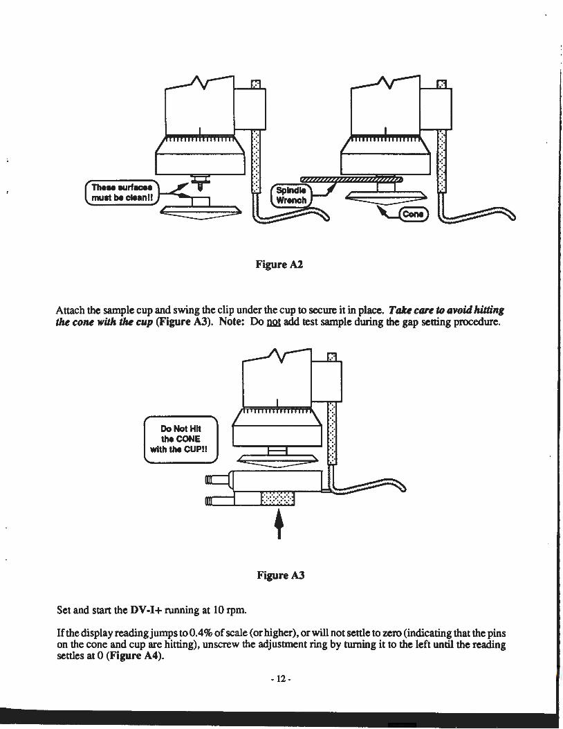
The• .urfacea must be clean!! ,.....,..,__.....,
Figure A2
·:
::· .:·
Attach the sample cup and swing the clip under the cup to secure it in place. Talce care to avoid hitting the cone with 1M cup (Figure A3). Note: Do run add test sample during the gap setting procedure.
Do Not Hit the CONE
with the CUP!!
Set and start the DV-1+ running at 10 rpm.
+ Figure A3
If the display reading jumps to 0.4% of scale (or higher), or will not settle to zero (indicating that the pins on the cone and cup are hitting), unscrew the adjustment ring by turning it to the left until the reading settles at 0 (Figure A4).
- 12-
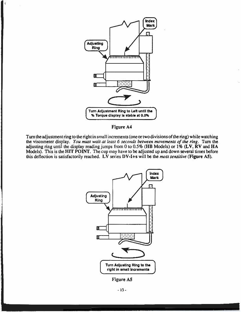
Turn Adjustment Ring to Left until the % Torque display Is stable at 0.0%
Figure A4
Turn the adjustment ring to the right in small increments (one or two divisions of the ring) while watching the viscometer display. You must wait at least 6 seconds between movements of the ring. Turn the adjusting ring until the display reading jumps from 0 to 0.5% (HB Models) or 1% (LV, RV and HA Models). This is the HIT POINT. The cup may have to be adjusted up and down several times before this deflection is satisfactorily reached. LV series DV-I+s will be the most sensitive (Figure AS).
Turn Adjusting Ring to the right In small Incrementa I
Figure AS
- 13-
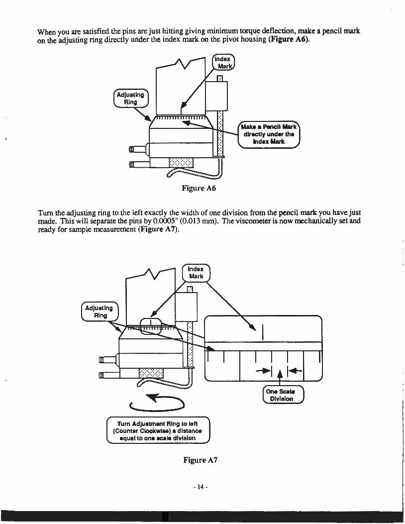
When you are satisfied the pins are just hitting giving minimum torque deflection, make a pencil mark on the adjusting ring directly under the index mark on the pivot housing (Figure A6).
Figure A6
Make a Pencil Mark directly under the
Index Mark
Turn the adjusting ring to the left exactly the width of one division from the pencil mark you have just made. This will separate the pins by 0.0005" (0.013 mm). The viscometer is now mechanically set and ready for sample measurement (Figure A 7).
Turn Adjustment Ring to left (Counter Clockwise) a distance
equal to one scale division
Figure A7
- 14-
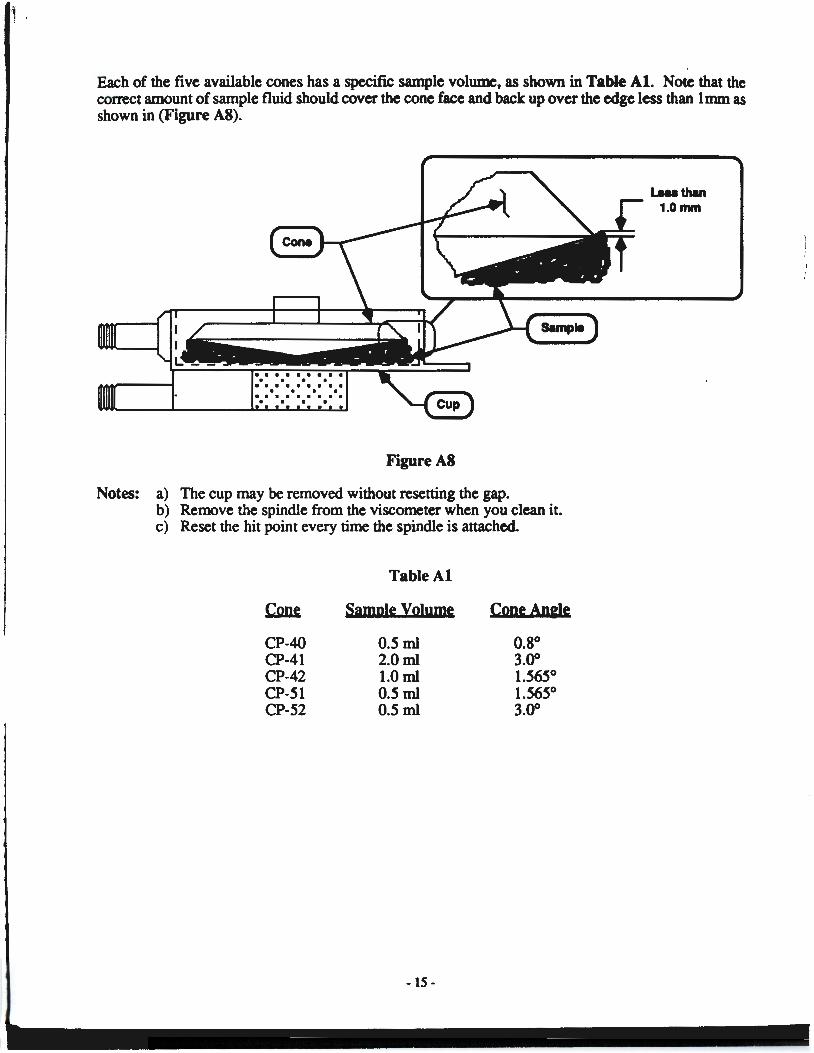
Each of the five available cones has a specific sample volume, as shown in Table Al. Note that the correct amount of sample fluid should cover the cone face and back up over the edge less than 1mm as shown in (Figure AS).
Figure AS
Notes: a) The cup may be removed without resetting the gap. b) Remove the spindle from the viscometer when you clean it. c) Reset the hit point every time the spindle is attached.
Table AI
~ Sample volume CopeApele
CP-40 0.5ml 0.8° CP-41 2.0ml 3.00 CP-42 l.Oml 1.565° CP-51 0.5ml 1.565° CP-52 0.5ml 3.00
- 15-
Leu than 1.0mm
)
I
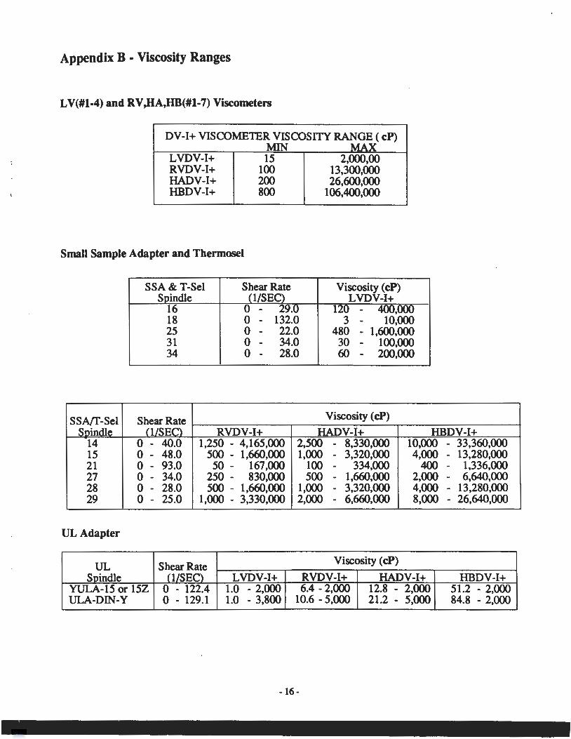
Appendix B • Viscosity Ranges
LV(#l-4) and RV,HA,HB(#l-7) Viscometers
DV-1+ VISCOMETER VISCOSITY RANGE ( cP)
LVDV-1+ RVDV-1+ HADV-1+ HBDV-1+
MIN MAX 15 2,000,00
100 13,300,000 200 26,600,000 800 106,400,000
Small Sample Adapter and Thermoset
SSA!f-Sel Soindle
14 15 21 27 28 29
UL Adapter
UL
SSA & T-Sel S indle
16 18 25 31 34
Shear Rate 0/SEC)
Shear Rate
RVDV-1+ 0 - 40.0 1,250 - 4,165,000 0 - 48.0 500 - 1 ,660,000 0 - 93.0 50 - 167,000 0 - 34.0 250 - 830,000 0 - 28.0 500 - 1,660,000 0 - 25.0 1,000 - 3,330,000
Shear Rate
Viscosity ( cP)
HADV-l+ 2,500 - 8,330,000 1,000 - 3,320,000
100 - 334,000 500 - 1,660,000
1,000 - 3,320,000 2,000 - 6,660,000
Viscosity ( cP)
HBDV-1+ 10,000 - 33,360,000 4,000 - 13,280,000
400 - 1,336,000 2,000 - 6,640,000 4,000 - 13,280,000 8,000 - 26,640,000
Soindle 0/SEC) LVDV-1+ RVDV-1+ HADV-1+ HBDV-1+ YULA-15 or 15Z 0 - 122.4 1.0 - 2,000 6.4-2,000 12.8 - 2,000 51.2 - 2,000 ULA-DIN-Y 0 - 129.1 1.0 - 3,800 10.6-5,000 21.2 - 5,000 84.8 - 2,000
-16-
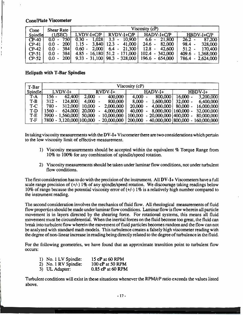
Cone/Plate Viscometer
Cone Shear Rate Viscosity ( cP) Soindle (1/SEC) LVDV-I+CLP RVDV-I+C/P HADV-I+C/P HBDV-I+C/P CP-40 0.0 - 750 0.30- 1,028 3.3 - 10,900 6.6 - 21,800 26.2 - 87,200 CP-41 0.0 - 200 1.15 - 3,840 12.3 - 41,000 24.6 - 82,000 98.4 - 328,000 CP-42 0.0 - 384 0.60- 2,000 6.4 - 21,300 12.8 - 42,600 51.2 - 170,400 CP-51 0.0 - 384 4.85 - 16,180 51.2 - 171,000 102.4 - 342,000 409.6 - 1,368,000 CP-52 0.0 - 200 9.33 - 31,100 98.3 - 328,000 196.6 - 654,000 786.4 - 2,624,000
Helipath with T -Bar Spindles
T-Bar Viscosity ( cP) Soindle LVDV-1+ RVDV-1+ HADV-1+ HBDV-1+
T-A 156- 62,400 2,000 - 400,000 4,000 - 800,000 16,000- 3,200,000 T-B 312- 124,800 4,000 - 800,000 8,000 - 1,600,000 32,000- 6,400,000 T-C 780- 312,000 10,000 - 2,000,000 20,000 - 4,000,000 80,000- 16,000,000 T-D 1560- 624,000 20,000 - 4,000,000 40,000 - 8,000,000 160,000- 32,000,000 T-E 3900 - 1,560,000 50,000 - 10,000,000 100,000 - 20,000,000 400,000- 80,000,000 T-F 7800 - 3,120,000 100,000 - 20,000,000 200,000 - 40,000,000 800,000 - 160,000,000
In taking viscosity measurements with the DV-I+ Viscometer there are two considerations which pertain to the low viscosity limit of effective measurement.
1) Viscosity measurements should be accepted within the equivalent% Torque Range from 10% to 100% for any combination of spindle/speed rotation.
2) Viscosity measurements should be taken under laminar flow conditions, not under turbulent flow conditions.
The first consideration has to do with the precision of the instrument All DV -I+ Viscometers have a full scale range precision of ( +/-) 1% of any spindle/speed rotation. We discourage taking readings below 10% of range because the potential viscosity error of ( +/-) 1% is a relatively high number compared to the instrument reading.
The second consideration involves the mechanics of fluid flow. All rheological measurements of fluid flow properties should be made under laminar flow conditions. Laminar flow is flow wherein all particle movement is in layers directed by the shearing force. For rotational systems, this means all fluid movement must be circumferential. When the inertial forces on the fluid become too great, the fluid can break into turbulent flow wherein the movement of fluid particles becomes random and the flow can not \>e analyzed with standard math models. This turbulence creates a falsely high viscometer reading with the degree of non-linear increase in reading being directly related to the degree of turbulence in the fluid.
For the following geometries, we have found that an approximate transition point to turbulent flow occurs:
1) No.1 LV Spindle: 2) No. 1 RV Spindle: 3) UL Adapter:
15 cP at 60 RPM 100 cP at 50 RPM 0.85 cP at 60 RPM
Turbulent conditions will exist in these situations whenever the RPM/cP ratio exceeds the values listed above.
- 17-
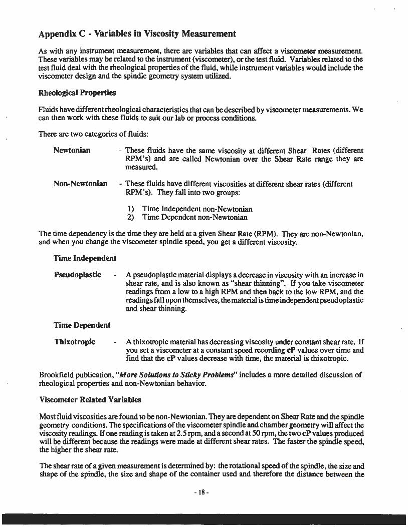
Appendix C - Variables in Viscosity Measurement
As with any instrument measurement, there are variables that can affect a viscometer measurement. These variables may be related to the instrument (viscometer), or the test fluid. Variables related to the test fluid deal with the rheological properties of the fluid, while instrument variables would include the viscometer design and the spindle geometry system utilized.
Rheological Properties
Fluids have different rheological characteristics that can be described by viscometer measurements. We can then work with these fluids to suit our lab or process conditions.
There are two categories of fluids:
Newtonian - These fluids have the same viscosity at different Shear Rates (different RPM's) and are called Newtonian over the Shear Rate range they are measured.
Non-Newtonian - These fluids have different viscosities at different shear rates (different RPM's). They fall into two groups:
1) Time Independent non-Newtonian 2) Time Dependent non-Newtonian
The time dependency is the time they are held at a given Shear Rate (RPM). They are non-Newtonian, and when you change the viscometer spindle speed, you get a different viscosity.
Time Independent
Pseudoplastic
Time Dependent
Thixotropic
A pseudoplastic material displays a decrease in viscosity with an increase in shear rate, and is also known as "shear thinning". If you take viscometer readings from a low to a high RPM and then back to the low RPM, and the readings fall upon themselves, the material is time independent pseudoplastic and shear thinning. ·
A thixotropic material has decreasing viscosity under constant shear rate. If you set a viscometer at a constant speed recording cP values over time and find that the cP values decrease with time, the material is thixotropic.
Brookfield publication, "More Solutions to Sticky Problems" includes a more detailed discussion of rheological properties and non-Newtonian behavior.
Viscometer Related Variables
Most fluid viscosities are found to be non-Newtonian. They are dependent on Shear Rate and the spindle geometry conditions. The specifications of the viscometer spindle and chamber geometry will affect the viscosity readings. If one reading is taken at 2.5 rpm, and a second at 50 rpm, the two cP values produced will be different because the readings were made at different shear rates. The faster the spindle speed, the higher the shear rate.
The shear rate of a given measurement is determined by: the rotational speed of the spindle, the size and shape of the spindle, the size and shape of the container used and therefore the distance between the
- 18-
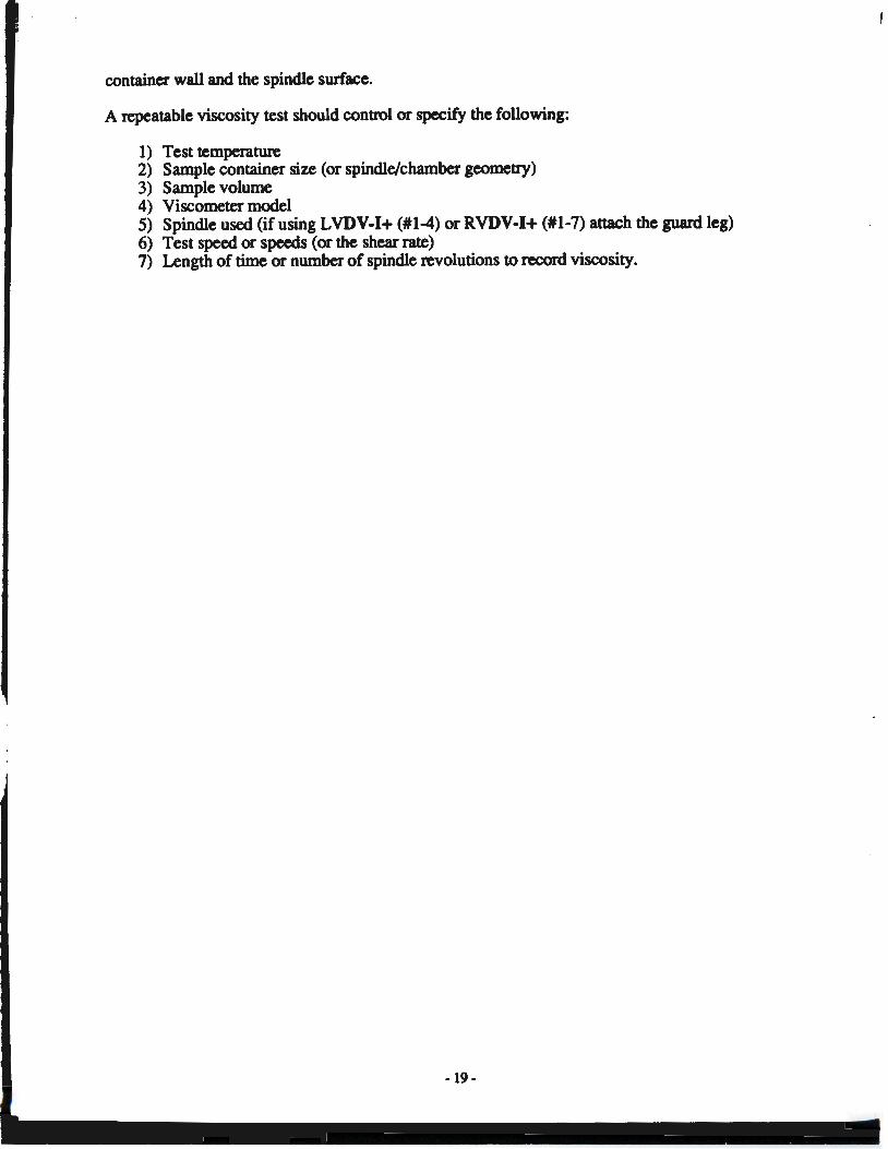
container wall and the spindle surface.
A repeatable viscosity test should control or specify the following:
1) Test temperature 2) Sample container size (or spindle/chamber geometry) 3) Sample volume 4) Viscometer model 5) Spindle used (if using LVDV-1+ (#1-4) or RVDV-1+ (#1-7) attach the guard leg) 6) Test speed or speeds (or the shear rate) 7) Length of time or number of spindle revolutions to record viscosity.
-19-
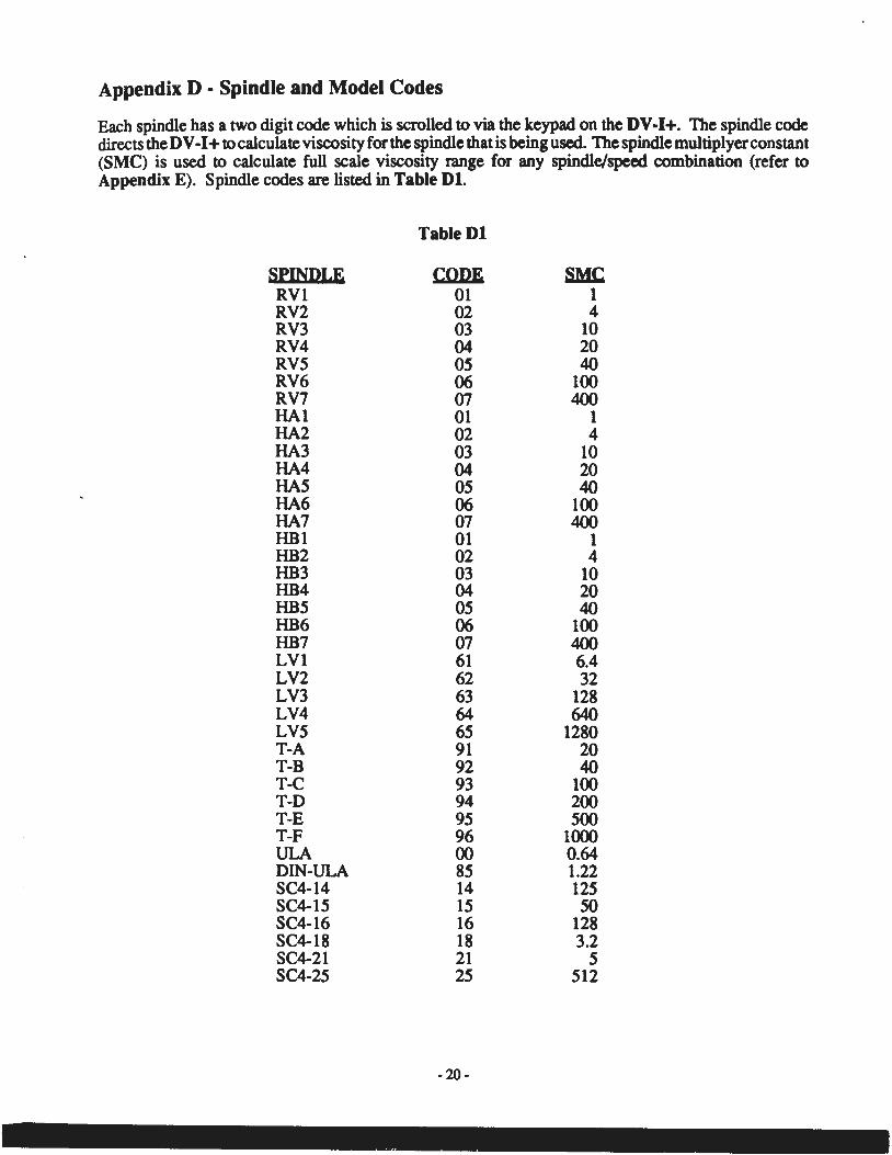
Appendix D • Spindle and Model Codes
Each spindle has a two digit code which is scrolled to via the keypad on the DV-1+. The spindle code directs the DV -I+ to calculate viscosity for the spindle that is being used. The spindle multiplyerconstant (SMC) is used to calculate full scale viscosity range for any spindle/speed combination (refer to Appendix E). Spindle codes are listed in Table Dl.
Table Dl
SEI!SDLE CODE we RVl 01 1 RV2 02 4 RV3 03 10 RV4 04 20 RV5 05 40 RV6 06 100 RV7 07 400 HAl 01 1 HA2 02 4 HA3 03 10 HA4 04 20 HAS 05 40 HA6 06 100 HA7 07 400 HBl 01 1 HB2 02 4 HB3 03 10 HB4 04 20 HB5 05 40 HB6 06 100 HB7 07 400 LVI 61 6.4 LV2 62 32 LV3 63 128 LV4 64 640 LV5 65 1280 T-A 91 20 T-B 92 40 T-C 93 100 T-D 94 200 T-E 95 500 T-F 96 1000 ULA 00 0.64 DIN-ULA 85 1.22 SC4-14 14 125 SC4-15 15 50 SC4-16 16 128 SC4-18 18 3.2 SC4-21 21 5 SC4-25 25 512
-20-
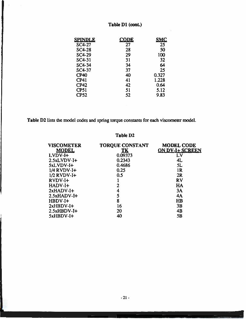
Table Dl (cont.)
SPINDLE CODE we SC4-27 27 25 SC4-28 28 50 SC4-29 29 100 SC4-31 31 32 SC4-34 34 64 SC4-37 37 25 CP40 40 0.327 CP41 41 1.228 CP42 42 0.64 CP51 51 5.12 CP52 52 9.83
Table D2 lists the model codes and spring torque constants for each viscometer model.
VISCOMETER MODEL
LVDV-1+ 2.5xLVDV-I+ 5xLVDV-1+ l/4RVDV-I+ l/2RVDV-I+ RVDV-1+ HADV-1+ 2xHADV-I+ 2.5xHADV-I+ HBDV-1+ 2xHBDV-I+ 2.5xHBDV-I+ 5xHBDV-I+
Table D2
TORQUE CONSTANT IK
0.09373 0.2343 0.4686 0.25 0.5 1 2 4 5 8 16 20 40
-21-
MODEL CODE ON DY-1+ SCREEN
LV 4L 5L lR 2R RV HA 3A 4A HB 3B 4B 5B
Appendix E - Calibration Procedures
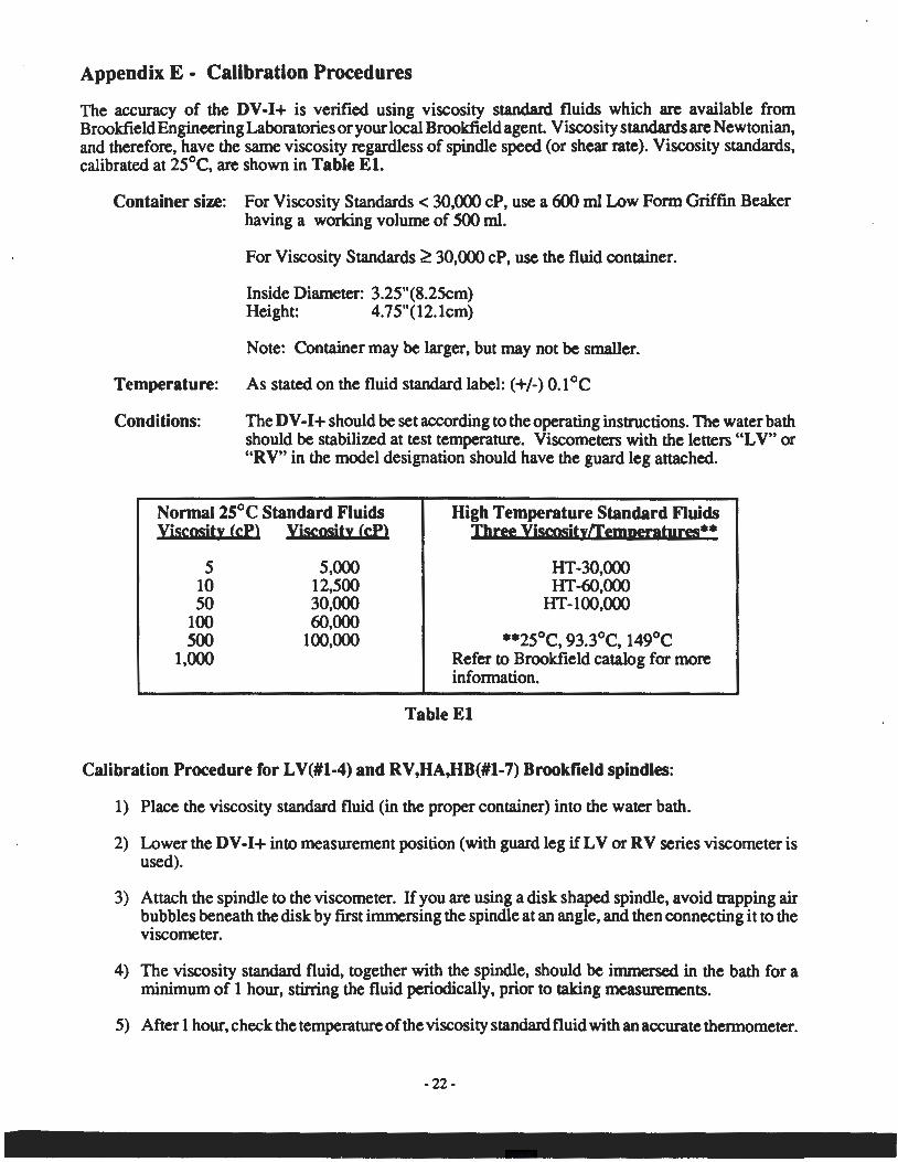
The accuracy of the DV-1+ is verified using viscosity standard fluids which are available from Brookfield Engineering Laboratories or your local Brookfield agent. Viscosity standards are Newtonian, and therefore, have the same viscosity regardless of spindle speed (or shear rate). Viscosity standards, calibrated at 25°C, are shown in Table El.
Container size: For Viscosity Standards< 30,000 cP, use a 600 ml Low Form Griffin Beaker having a working volume of 500 ml.
For Viscosity Standards ~ 30,000 cP, use the fluid container.
Inside Diameter: 3.25"(8.25cm) Height: 4.75"(12.1cm)
Note: Container may be larger, but may not be smaller.
Temperature: As stated on the fluid standard label: ( +/-) 0.1 °C
Conditions: The DV -I+ should be set according to the operating instructions. The water bath should be stabilized at test temperature. Viscometers with the letters "LV" or "RV" in the model designation should have the guard leg attached.
Normal 25°C Standard Fluids viscosity (cPl . Viscosity (cPl
5 10 50
100 500
1,000
5,000 12,500 30,000 60,000
100,000
High Temperature Standard Fluids Three viscositytremperatures**
HT-30,000 HT -60,000
HT -100,000
**25°C, 93.3°C, 149°C Refer to Brookfield catalog for more information.
Table El
Calibration Procedure for LV(#l-4) and RV,HA,HB(#l-7) Brookfield spindles:
1) Place the viscosity standard fluid (in the proper container) into the water bath.
2) Lower the DV-1+ into measurement position (with guard leg if LV or RV series viscometer is used).
3) Attach the spindle to the viscometer. If you are using a disk shaped spindle, avoid trapping air bubbles beneath the disk by first immersing the spindle at an angle, and then connecting it to the viscometer.
4) The viscosity standard fluid, together with the spindle, should be immersed in the bath for a minimum of 1 hour, stirring the fluid periodically, prior to taking measurements.
5) After 1 hour, check the temperature of the viscosity standard fluid with an accurate thermometer.
-22-
6) H the fluid is at test temperature ( +/- 0.1 °C of the specified temperature, normally 25°C), measure the viscosity and record the viscometer reading.
Note: The spindle must rotate at least five (5) times before readings are taken.
7) The viscosity reading should equal the cP value on the viscosity fluid standard to within the combined accuracies of the viscometer and the standard (as discussed in the section entitled, Interpretation of Calibration Test Results, page 24).
Calibration Procedure for a Small Sample Adapter
When a Small Sample Adapter is used, the water jacket is connected to the water bath and the water is stabilized at the proper temperature:
1) Put the proper amount of viscosity standard fluid into the sample chamber. The amount varies with each spindle/chamber combination. (Refer to the Small Sample Adapter instruction manual.)
2) Place the sample chamber into the water jacket.
3) Put the spindle into the test fluid and attach the extension link, coupling nut and free hanging spindle (or directly attach the solid shaft spindle) to the DV-1+.
4) Allow 30 minutes for the viscosity standard, sample chamber and spindle to reach test temperature.
5) Measure the viscosity and record the viscometer reading.
Note: The spindle must rotate at least five (5) times before a viscosity reading is taken.
Calibration Procedure for a Thermosel System
When a Thermosel System is used, the controller stabilizes the Thermo Container at the test temperature.
1) Put the proper amount ofHT viscosity standard fluid into the HT-2 sample chamber. The amount varies with the spindle used. (Refer to the Thermosel instruction manual).
2) Place the sample chamber into the Thermo Container.
3) Put the spindle into the test fluid and attach the extension link, coupling nut and free hanging spindle (or directly attach the solid shaft spindle) to the DV-1+.
4) Allow 30 minutes for the viscosity standard, sample chamber and spindle to reach test temperature.
5) Measure the viscosity and record the viscometer reading.
Note: The spindle must rotate at least five (5) times before a viscosity reading is taken.
Calibration Procedure using UL or DIN UL Adapters
When a UL or DIN UL Adapter is used, the water bath is stabilized at the proper temperature:
1) Put the proper amount of viscosity standard fluid into the UL Tube. (Refer to the UL Adapter instruction manual).
-23-
. - ·---- - . -
2) Attach the spindle (with extension link and coupling nut) onto the DV-1+.
3) Attach the tube to the mounting channel.
4) Lower the tube into the water bath reservoir, or if using the ULA-40Y water jacket, connect the inlet/outlets to the bath external circulating pump.
5) Allow 30 minutes for the viscosity standard, sample chamber and spindle to reach test temperature.
6) Measure the viscosity and record the viscometer reading.
Note: The spindle must rotate at least five (5) times before a viscosity reading is taken.
Calibration Procedure using a Helipath Stand and T -Bar Spindles
When a Helipath Stand and T-Bar spindles are used:
Remove the T -bar spindle and select a standard LV ( # 1-4) or RV ,HA,HB( #1-7) spindle. Follow the procedures for LV(# 1-4) and RV ,HA,HB ( # 1-7) Brookfield spindles outlined above.
T -Bar spindles should not be used for verifying calibration of the DV -I+ Viscometer.
Interpretation of Calibration Test Results:
When verifying the calibration of the DV-1+, the instrument and viscosity standard fluid error must be combined to calculate the total allowable error.
The DV -I+ is accurate to ( +/-) 1% of any full scale spindle/speed viscosity range.
Brookfield Viscosity Standards Fluids are accurate to ( +/-) 1% of their stated value.
EXAMPLE: Calculate the acceptable range of viscosity using RVDV-1+ with RV-3 Spindle at 2 RPM; Brookfield Standard Fluid 12,500 with a viscosity of 12,257 cP at 25°C:
1) Calculate full scale viscosity range using the equation:
Full Scale Viscosity Range [cP] = TK • SMC • 1&tf Where: TK = 1.0 from Table Dl
SMC = 10 from Table Dl
Full Scale Viscosity Range = 1 • 10 • 10·000 = 50,000 cP 2
The viscosity is accurate to (+I-) 500 cP (which is 1% of 50,000)
2) The viscosity standard fluid is 12,257 cP. Its accuracy is (+/-)1% of 12,257 or (+/-)122.57 cP.
3) Total allowable error is (122.57 + 500) cP = (+/-) 622.57 cP.
-24-
4) Therefore, any viscosity reading between 11,634.4 and 12,879.6 cP indicates that the viscometer is operating correctly. Any reading outside these limits may indicate a viscometer problem. Contact the Brookfield technical sales department or your local· Brookfield dealer/distributor with test results to determine the nature of the problem.
- 2S-
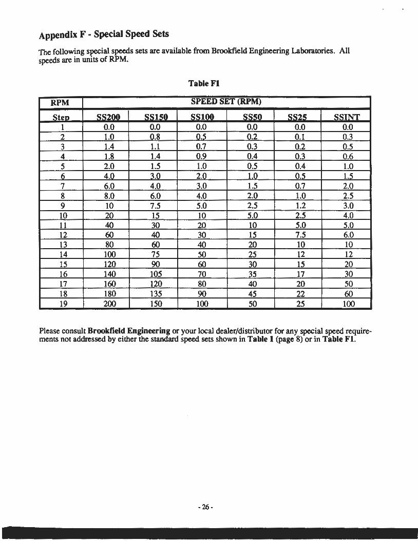
Appendix F • Special Speed Sets
The following special speeds sets are available from Brookfield Engineering Laboratories. All speeds are in units of RPM.
Table Fl
RPM SPEED SET (RPM)
Sten SS200 SSlSO SSlOO SSSO_ SS25 SSINT 1 0.0 0.0 0.0 0.0 0.0 0.0 2 1.0 0.8 0.5 0.2 0.1 0.3 3 1.4 1.1 0.7 0.3 0.2 0.5 4 1.8 1.4 0.9 0.4 0.3 0.6 5 2.0 1.5 1.0 0.5 0.4 1.0 6 4.0 3.0 2.0 1.0 0.5 1.5 7 6.0 4.0 3.0 1.5 0.7 2.0 8 8.0 6.0 4.0 2.0 1.0 2.5 9 10 7.5 5.0 2.5 1.2 3.0 10 20 15 10 5.0 2.5 4.0 11 40 30 20 10 5.0 5.0 12 60 40 30 15 7.5 6.0 13 80 60 40 20 10 10 14 100 75 50 25 12 12 15 120 90 60 30 15 20 16 140 105 70 35 17 30 17 160 120 80 40 20 50 18 180 135 90 45 22 60 19 200 150 100 50 25 100
Please consult Brookfield Engineering or your local dealer/distributor for any special speed requirements not addressed by either the standard speed sets shown in Table 1 (page 8) or in Table Fl.
-26-
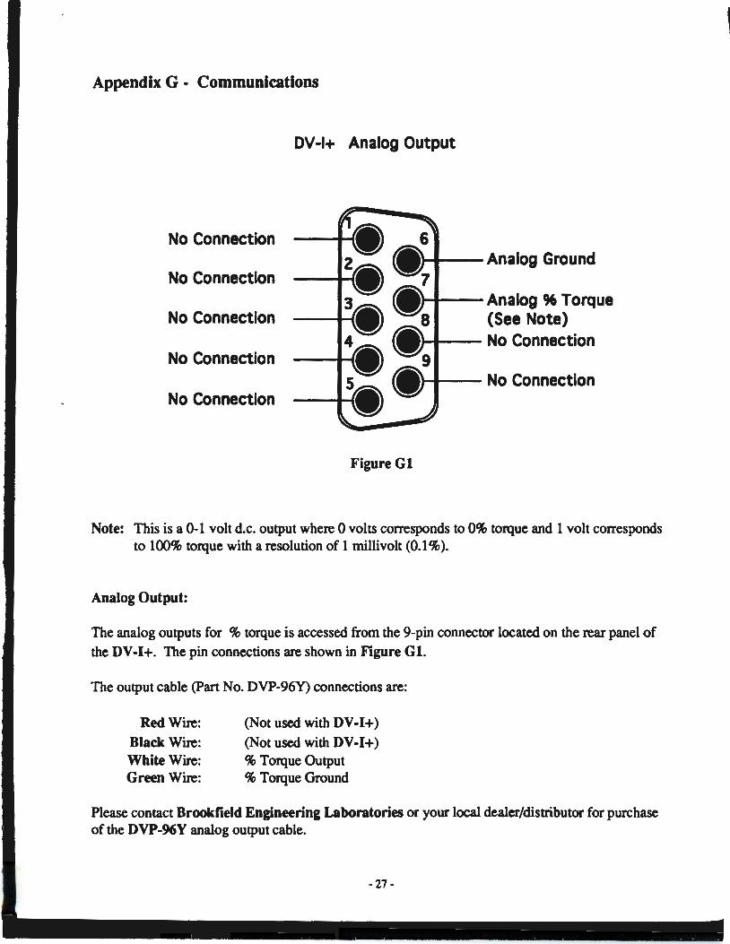
Appendix G • Communications
DV-1+ Analog Output
No Connection
No Connection .....,. __ Analog 96 Torque
No Connection (See Note) ,....... __ No Connection
No Connection
No Connection
Figure Gl
Note: This is a 0-1 volt d.c. output where 0 volts corresponds to 0% torque and 1 volt corresponds to 100% torque with a resolution of 1 millivolt (0.1 %).
Analog Output:
The analog outputs for % torque is accessed from the 9-pin connector located on the rear panel of
the DV-1+. The pin connections are shown in Figure Gl.
The output cable (Part No. DVP-96Y) connections are:
Red Wire:
Black Wire: White Wire: Green Wire:
(Not used with DV-1+)
(Not used with DV-1+) % Torque Output % Torque Ground
Please contact Brookfield Engineering Laboratories or your local dealer/distributor for purchase of the DVP-96Y analog output cable.
~ 27-
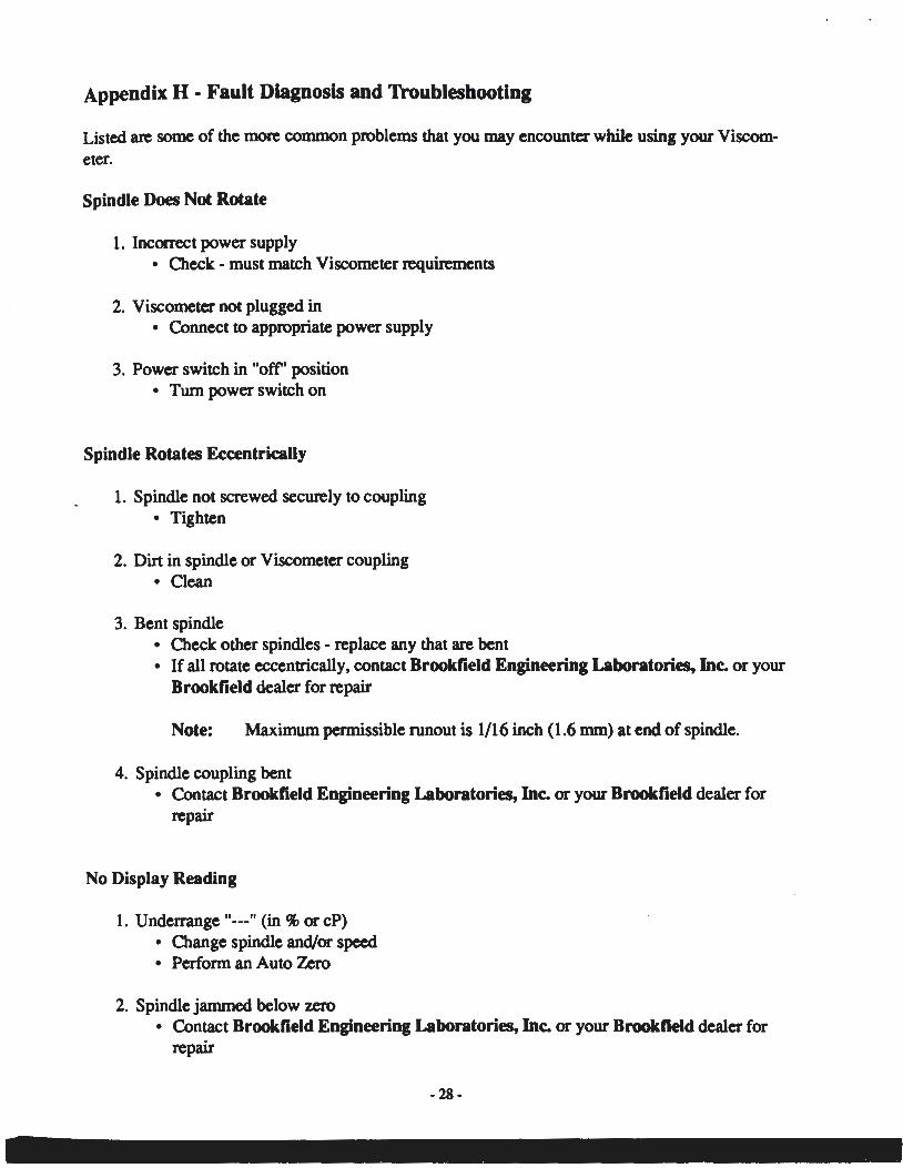
Appendix H • Fault Diagnosis and Troubleshooting
Listed are some of the more common problems that you may encounter while using your Viscometer.
Spindle Does Not Rotate
1. Incorrect power supply • Check - must match Viscometer requirements
2. Viscometer not plugged in • Connect to appropriate power supply
3. Power switch in "ofr' position • Turn power switch on
Spindle Rotates Eccentrically
1. Spindle not screwed securely to coupling • Tighten
2. Dirt in spindle or Viscometer coupling • Clean
3. Bent spindle • Check other spindles - replace any that are bent • If all rotate eccentrically, contact Brookfield Engineering Laboratories, Inc. or your
Brookfield dealer for repair
Note: Maximum permissible runout is 1/16 inch (1.6 mm) at end of spindle.
4. Spindle coupling bent • Contact Brookfield Engineering Laboratories, Inc. or your Brookfield dealer for
repair
No Display Reading
1. Underrange "---" (in %or cP) • Change spindle and/or speed • Perform an Auto Zero
2. Spindle jammed below zero • Contact Brookfield Engineering Laboratories, Inc. or your Brookfield dealer for
repair
-28-
Display Reading Over 100
1. Overrange "EEE" (in % and cP) • Change spindle and/or speed
Viscometer Will Not Return to Zero
1. Pivot point or jewel bearing faulty • Perform calibration check • Contact Brookfield Engineering Laboratories, Inc. or your Brookfield dealer for
repair
Display Reading Will Not Stabilize
1. Check for erratic spindle rotation • Verify power supply • Contact Brookfield Engineering Laboratories, Inc. or your Brookfield dealer for
repair
2. Bent spindle or spindle coupling • Check • Contact Brookfield Engineering Laboratories, Inc. or your Brookfield dealer for
repair
3. Temperature fluctuation in sample fluid • Use temperature bath control
4. Special characteristic of sample fluid • Refer to Appendix C
Inaccurate Readings
1. Incorrect spindle/speed selection
2. Incorrect spindle code entry
3. Non-standard test parameters
4. Temperature fluctuations
5. Incorrect equipment selection
- 29 -
Recorder Pen Moves in Wrong Direction
1. Output polarity reversed • Reverse leads
No Recorder Response
1. Viscometer is at zero reading
2. Recorder is off
3. Output cable leads shorted
4. Recorder is in standby
5. Range setti~g is incorrect.
-30-
Appendix I • Warranty Repair and Service
Warranty
Brookfield Viscometers are guaranteed for one year from date of purchase against defects in materials and workmanship. They are certified against primary viscosity standards traceable to the National Institute of Standards and Technology (NIST). The Viscometer must be returned to Brookfield Engineering Laboratories, Inc. or the Brookfield dealer from whom it was purchased for no charge warranty service. Transportation is at the purchaser's expense. The Viscometer should be shipped in its carrying case together with all spindles originally provided with the instrument.
For repair or service in the United States, return to:
Brookfield Engineering Laboratories, Inc. 240 Cushing Street
Stoughton, MA 02072 U.S.A.
Telephone: (617) 344-4310 FAX: (617) 344-7141
For repair or service o._.tside the United States, consult Brookfield Engineering Laboratories, Inc. or the dealer from whom you purchased the instrument.
For repair or service in the United Kingdom, return to:
Brookfield Viscometers Limited The Seedbed Centre
Langston Road Lough ton, Essex IG 10 3TQ, United Kingdom
Telephone: (44) 81/502 4220 FAX: (44) 81/502 3714
- 31 -

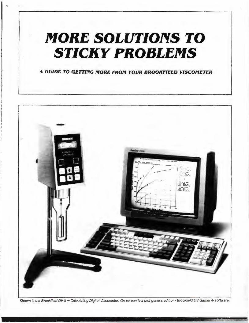
MORE SOLUTIOIYS TO STICKY PROBLEMS
A GUIDE TO GETTIIYG MORE FROM YOUR BROOKFIELD VISCOMETER
l 5.~: .. ~ . .. + • " ~ ••
.::. '.:. .-~ - . + , ,';,'~ ;, : ~r~ . ,
Shown is the Brookfield DV-11+ Calculating Digital Viscometer. On screen is a plot generated from Brookfield DV Gather+ software.
INTRODUCTION
MORE SOLUTIONS TO STICKY PROBLEMS
CHAPTER 5
CHAPTER 1
1.1 Why Make Rheological Measurements? 2
1.2 Thinking Rheo-Loglcally 2
1.3 Three Schools of Thought on VIscosity Measurement 2
1.3.1 The Pragmatic School 2
1.3.2 The Theoretical School 2
1.3.3 The Academic School 2
CHAPTER 2
2.1 Equipment for Specific Situations 3
2.1.1 Vlscometers 3
2.1.2 Spindle Geometries 3
2.1.3 Temperature Control 4
2.1.4 Small Sample Volume 4
2.1.5 Low Viscosity 5
2.1 .6 High Temperature 5
2.1.7 Defined Shear Rate 6
2.1.8 High Shear Rate 6
2.1.9 Non-Flowing Sample Materials 6
2.1.10 Fumes and Hazardous Locations 6
2.1.11 Process Control 7
CHAPTER 3
3.1 Why You Should Read This Chapter 7
3.2 How the Brookfield Viscometer Works 7
3.3 Viscosity Measurement Techniques 8 3.3.1 Record keeping 8 3.3.2 The Spindle and the Guard 8 3.3.3 Selecting a Spindle/Speed 8 3.3.4 Sample Container Size 9 3.3.5 Sample Conditions 9 3.3.6 Spindle Immersion 9 3.3.7 Sensitivity and Accuracy 9 3.3.8 Obtaining a Viscometer Reading 10 3.3.9 A Calibration Check 10 3.3.10 Recallbrating the Brookfield Viscometer 11
3.4 Viscometer Maintenance 11 3.5 Viscometer Troubleshooting 12
CHAPTER 4
4.1 Coming to Grips with Rheology 13 4.2 Viscosity 13 4.3 Newtonian Fluids 13 4.4 Non-Newtonian Fluids 14 4.5 Thixotropy and Rheopexy 14 4.6 Laminar and Turbulent Flow 15 4.7 What Affects the Rheological Property? 15
4.7.1 Temperature 15 4.7.2 Shear Rate 16 4.7.3 Measuring Conditions 16 4.7.4 Time 16 4.7.5 Previous History 16 4.7.6 Composition and Additives 16 4.7.7 Special Characteristics of Dispersions
and Emulsions 17
5.1 Advanced Methods for Rheological Analysis 17 5.2 Defining Operating Parameters of Various Spindle
Geometries 18 5.2.1 Cylindrical Spindles 18 5.2.2 Coaxial Cylinders 18 5.2.3 Cone and Plate 18 5.2.4 Disc and T·Bar Spindles 18
5.3 Analyzing Time-Independent Non-Newtonian Fluids 18 5.3.1 Ratio Methods 19 5.3.2 Graphic Methods 19 5.3.3 Template Method 19 5.3.4 Yield Stress Determination 19
5.4 Analyzing Time-Dependent Non-Newtonian Fluids 20
5.5 Temperature Dependence of Viscosity 21
5.6 Miscellaneous Methods 21
APPENDIX
A.1 Specifications, Ranges, and Operating Parameters 22 A.1 .1 Dial-Reading Viscometer 22 A.1.2 Digital Viscometer 22 A.1.3 Wells-Brookfield Cone/Plate Viscometer 22 A.1.4 Disc Spindles 23 A.1.5 Cylindrical Spindles 23 A.1.6 Thermosei System 24 A.1.7 Small Sample Adapter 24 A.1 .8 UL Adapter 24 A.1.9 Hellpath Stand 25
A.2 ASTM Specifications 25 A.3 References 25
BROOKFIELD ENGINEERING LABORATORIES, INC. 240 Cushing Street.Stoughton, Massachusetts 02072 U.S.A. Phones: (617) 344-4310; 344-4313 Telex: 924497; 200195 Fax: (617) 344-7141 800.628-8139 (US ex MA)
INTRODUCTION
When a piece of technical equipment is marketed successfully for over fifty years, it is inevitable that a large body of experience will develop from the use of that equipment. Procedures are established, papers are published, standards are accepted, and a vast informal grapevine of advice grows amidst the community of users. Such is the case with the Brookfield Viscometer. Accepted as a standard of viscosity measurement around the world , the Brookfield Viscometer is the nucleus of a library of information that encompasses the experiences of thousands of users in a seemingly endless variety of applications.
This library, however, is not gathered conveniently together in any single location. It is fragmented, scattered here and there in technical journals, in test
- reports, in the notes made by technicians, researchers, and quality control people. For many users (particularly those new to the field of viscosity measurement), it is extremely difficult to gain access to information generated outside their own company or industry. Brookfield Engineering Laboratories has for many years acted as a clearinghouse for this type of information, reprinting a variety of technical papers on the subject of viscosity measurement and making them available at no cost. This program has helped many people benefit from the experiences of others.
There is a middle ground, however, between the specific technical information provided in these papers and the basic operating procedures outlined in an instruction manual. We have been requested many times over the years to publish a book that would bridge the gap between the elementary and the advanced, a sort of extended "user's manual" that would guide the way for the person wishing to explore in greater depth the field of viscosity measurement, with an emphasis on Brookfield equipment.
The book you hold in your hand is the result of those requests. It does not replace your instruction manual, nor does it replace the specific technical papers already or yet to be published. It is also not a textbook on rheology. Rather, it is a guide to help point out the way to getting more from your Brookfield Viscometer. It does this in several ways:
• by offering practical advice on the use and maintenance of the Viscometer gleaned from our experience and that of our customers; • by suggesting ways in which specific pieces of hardware may be used to solve viscosity measurement problems; • by explaining the basic principles of rheology and their relation to measurements made with Brookfield equipment; • by discussing factors that affect rheological behavior and how these may be controlled; • by outlining advanced mathematical procedures for detailed analysis of viscosity data; • by consolidating a variety of useful range tables, formulas, and specifications for many Brookfield Viscometers and accessories.
We hope that you will find this book useful and refer to it often. It is our attempt to answer all at once many of the questions we have been asked over the years. If you have any questions that are not answered here, or if you want to suggest improvements or changes for future editions, please feel free to contact us. It was, after all, the input of people like yourself that made this book possible in the first place.
MORE SOLUTIONS TO STICKY PROBLEMS-----------------------
Chapter 1
1.1 Why Make Rheological Measurements? Anyone beginning the process of learning to think
Rheo-Logically must first ask the question, "Why should I make a viscosity measurement?" The answer lies in the experiences of thousands of people who have made such measurements, showing that much useful behavioral and predictive information for various products can be obtained, as well as knowl· edge of the effects of processing, formulation changes, aging phenomena, etc.
A frequent reason for the measurement of rheo· logical properties can be found in the area of quality control, where raw materials must be consistent from batch to batch. For this purpose, flow behavior is an indirect measure of product consistency and quality.
Another reason for making flow behavior studies is that a direct assessment of processability can be obtained. For example, a high viscosity liquid requires more power to pump than a low viscosity one. Knowing its rheological behavior, therefore, is useful when designing pumping and piping systems.
It has been suggested that rheology is the most sensitive method for material characterization because flow behavior is responsive to properties such as molecular weight and molecular weight distribution. This relationship is useful in polymer synthesis, for example, because it allows relative differences to be seen without making molecular weight measurements. Rheological measurements are also useful in following the course of a chemical reaction. Such measurements can be employed as a quality check during production or to monitor and/or control a process. Rheological measurements allow the study of chemical, mechanical, and thermal treatments, the effects of additives, or the course of a curing reaction. They are also a way to predict and control a host of product properties, end use performance and material behavior.
1.2 Thinking Rhea-Logically To begin, consider the question, "Can some rheo·
logical parameter be employed to correlate with an aspect of the product or process?" To determine this, an instinct must be developed for the kinds of chemical and physical phenomena which affect the rheological response. For the moment, assume this information is known and several possibilities have been identified. The next step is to gather preliminary rheological data to determine what type of flow behavior is characteristic of the system under con· sideration. At the most basic level, this involves making measurements with whichever Brookfield Viscometer is available and drawing some con· elusions based on the descriptions of flow behavior types in Chapter 4.
Once the type of flow behavior has been identified, more can be understood about the way components of the system interact (more information on what affects the rheological property can be found in Section 4.7).
2
The data thus obtained may then be fitted to one of the mathematical models which have been sue· cessfuliy used with Brookfield instruments. Many of these models may be found in Chapter 5.
Such mathematical models rang.l from the very simple to the very complex. Some of them merely involve the plotting of data on graph paper; others require calculating the ratio of two numbers. Some are quite sophisticated and require the use of programmable calculators or computers. This kind of analysis is the best way for getting the most from your data and often results in one or two "constants" which summarize the data and can be related to product or process performance.
Once a correlation has been developed between rheological data and product behavior, the procedure can then be reversed and rheological data may be used to predict performance and behavior.
1.3 Three Schools of Thought on Viscosity Measurement
In our experience there are basically three schools of thought on the use of viscometers in applications rheology. We present them here and invite you to decide which you fall into, remembering that there is no "right" one and that each has its merits.
1.3.1 The Pragmatic School The first school of thought is the most
pragmatic.The person who adheres to this school cares only that the Brookfield Viscometer generates numbers that tell something useful about a product or process. This person has little or no concern about rheological theory and measurement parameters expressed in absolute terms. Quality control and plant production applications are typical of this category. 1.3.2 The Theoretical School
The second school of thought involves a more theoretical approach. Those adhering to this school know that some types of Brookfield Viscometers will not directly yield defined shear rates and absolute viscosities for non-Newtonian fluids. However, these people often find that they can develop correlations of "dial viscosity" with important product or process parameters.
Many people follow this school of thought. The applications rheology literature is replete with statements along the line of "I know the data isn't academically defined, but I keep this fact in mind and treat the multi-point rheology information as if it were." In many cases, this produces eminently satisfying results and eliminates the necessity of buying a highly sophisticated and very expensive piece of rheological equipment. 1.3.3 The Academic School
The third school of thought is quite academic in nature. People adhering to this school require
that all measurement parameters, particularly shear rate and shear stress, be defined and known . They need equipment with defined geometries, such as cone and plate or coaxial cylinders. Examples from the Brookfield line would be the Wells-Brookfield Cone/Plate Viscometer and the UL Adapter, Small Sample Adapter, and Thermosel accessories. With this equipment the shear rate is defined and
accurate absolute viscosities are obtained directly.
That, then , is our view of the three schools of thought on viscosity measurement. You may need to th ink in terms of any or all of these depending on your background, approach , goals, and type of equipment available. Brookfield Viscometer users fall into all three; the following chapters present informat ion of use to each.
Chapter 2
2.1 Equipment for Specific Situations The purpose of this chapter is to provide an over
view of Brookfield 's entire line of Viscometers and related accessories, and to suggest ways in which these products may be helpful in solving specific viscosity measurement problems. This information will be useful to people adhering to all three schools of thought on viscosity measurement.
The equipment has been organized into functional groups to help you quickly zero in on the items of most interest to you:
2.1.1 2.1.2 2.1.3 2.1.4 2.1.5 2.1 .6 2.1.7 2.1.8 2.1.9 2.1.10 2.1.11
Viscometers Spindle Geometries Temperature Control Small Sample Volume Low Viscosity High Temperature Defined Shear Rate High Shear Rate Non-Flowing Sample Materials Fumes and Hazardous Locations Process Control
2.1.1. Viscometers Brookfield laboratory Viscometers are
available in three basic types : dial-reading (analog) , Digital, and programmable. The most significant difference between them is the manner in which the viscosity reading is displayed. The dial-reading type is read by noting the position of a pointer in relation to a rotating dial ; the Digital type is read by means of a 3-digit LED display. In addition , the Digital Viscometer includes a 0-1 Omv output that may be connected to a variety of devices, such as remote displays, controllers, and recorders.
In most respects dial-reading and Digital Viscometers are functionally similar. The operating procedures for both are essentially the same, they are available in the same model variations, they accept the same Brookfield accessories, and are generally interchangeable (model for model) in most viscosity specifications requiring Brookfield Viscometers.
The dial-reading type is the least expensive Brookfield Viscometer and is suitable for most
3
applications where samples are to be tested over a short period of time and a permanent detailed record of rheological behavior is not required . This is due to the fact that whi le the Viscometer rotates continuously, readings may be made only intermittently, when the pointer passes under the vision glass, or when the reading is held and the Viscometer stopped. Long term viscosity tests necessitate frequent operator attention , and some fast-act ing processes dictate continuous monitoring.
The Digital Viscometer, with its continuous sensing and recorder output, is more suited to such situations. It may be left unattended for long periods, and the recorder speed may be adjusted to provide a detailed record of even the fastest rheological processes. In addition, many operators prefer a digital display, which elimi nates the interpolation sometimes necessary when reading a dial. The Digital Viscometer however, cannot be hand-held during use, unlike the dial-reading type. Both types offer equivalent accuracy.
All Brookfield laboratory Viscometers are available both in standard spindle and cone/ plate configurations. See Section 2.1 .8 for more information on cone/plate spindle geometry. ·
It is not possible to convert a dial-reading Viscometer to a Digital Viscometer, or to connect a recorder to it.
There are many variations of the standard Viscometer models available, such as intermediate spring torques, alternative rotational speeds, and various physical modifications. Please consult Brookfield Engineering Laboratories or your dealer for details and availability.
2.1.2 Spindle Geometries All Brookfield Viscometers are supplied with
spindles suitable for most applications within the viscosity range of the instrument. There are, however, situations where specialized spindle geometries are necessary to obtain optimum results . Brookfield has available a wide variety of spindles and accessories to fulfi ll this need.
MORE SOLUTIONS TO STICKY PROBLEMS----------------------
Many are listed below. All Brookfield Viscometer spindles are con
structed of 300 series stainless steel for maintenance-free service in most applications; some are available coated for maximum corrosion resistance. Please inquire about special spindle materials and configurations for unusual applications. Disc Spindles
Provided as standard equipment with LV (spindles #2 and #3) and RV/HAIHB models (spindles #1 through #6), these are generalpurpose spindles for use in containers of 600 ml capacity or larger. Disc spindles produce accurate, reproducible apparent viscosity determinations in most fluids. The results obtained can be converted into viscosity functions by a mathematical procedure outlined in Technical Paper AR-82, available from Brookfield Engineering Laboratories. See Section 2.1.7 for information on spindle geometries that directly provide defined shear rates. Cylindrical Spindles
These spindles (LV #1 and #4, RV/HA/HB #7) provide a defined spindle geometry for calculating shear stress and shear rate values as well as viscosity. In all other respects their operating parameters are similar to those of disc spindles.
Because their defined geometry facilitates mathematical analysis, cylindrical spindles are particularly valuable when measuring nonNewtonian fluids. They are applicable to any Brookfield Viscometer model with the use of the appropriate range sheet. Cylindrical equivalents of the LV #2 and #3 disc spindles are also available. See Section 2.1.7 for information on other defined shear rate geometries. Coaxial Cylinders
Coaxial-cylinder geometry is indicated for applications where extremely well-defined shear rate and shear stress data is required, particularly when the sample volume is relatively small. Several Brookfield accessories feature coaxialcylinder geometry; each also has unique advantages for specific situations. These accessories are: the Small Sample Adapter (Section 2.1.4), the UL Adapter (Section 2.1 .5), and the Thermosel (Section 2.1.6). Cone/Plate Geometry
Cone/plate geometry offers absolute viscosity determinations with precise shear rate and shear stress information readily available. The sample volumes required are extremely small and the sample cup is jacketed for temperature control. Cone/plate geometry is particularly suitable for advanced rheological analysis of non-Newtonian fluids. It is available only on the Wells-Brookfield Cone/Plate Viscometer (see Section 2.1.8 for more information).
4
T-Bar Spindles Generally used in conjunction with the
Helipath Stand accessory (with which they are supplied as standard equipment), T-bar spindles make possible the measurement of non-flowing or slow-flowing materials such as pastes, gels, and creams. See Section 2.1.9.
2.1.3 Temperature Control In order to ensure maximum accuracy and
reproducibility in many viscosity measurement procedures, temperature control is highly recommended. The following systems are available from Brookfield: Temperature Baths
Constant-temperature baths are suitable for most viscosity measurement applications. They are available in two basic types: circulating, for use with jacketed devices such as the WellsBrookfield Cone/Plate Viscometer (Section 2.1.8) and the Small Sample Adapter (Section 2.1 .5); and reservoir/circulating, for all applications (this type can be used with jacketed devices as well as with any sample container that can be immersed in the bath's reservoir). Temperature baths are generally limited to a maximum operating temperature of approximately 120 degrees C (depending on the bath fluid used), and usually require auxiliary cooling devices for operation at or below ambient temperature. Refrigerated baths are also available. Contact Brookfield Engineering Laboratories or your dealer for more information. Thermosel System
This system is designed for the measurement of small samples in the temperature range of approximately 25 to 300 degrees C. Unlike a temperature bath, the Thermosel doesn't utilize a fluid medium for temperature control. For more information, see Section 2.1.6.
2.1.4 Small Sample Volume The standard sample container for most Brook
field Viscometers is a 600 ml low form Griffin beaker. Users often find it desirable or necessary to measure samples of smaller volume. Several Brookfield products feature small sample volumes: Small Sample Adapter
Specifically designed to facilitate the measurement of small samples, the Small Sample Adapter is a jacketed, coaxial-cylinder accessory that is compatible with all Brookfield Viscometers with the exception of cone/plate types. Depending on the model selected, the Small Sample Adapter utilizes sample volumes of 2.0 to 16.0 mi. Also depending on model, the Small Sample Adapter will measure viscosities from 5 cps to 10,000,000 cps at shear rates from 0.066 to 93.0 reciprocal seconds. The Small Sample Adapter's jacketed design permits
---------®mJmJilllFO~[]J]J connection to a circulating-type bath for excellent temperature control up to a recommended maximum of 100 degrees C. UL Adapter
The UL Adapter is primarily intended to allow viscosity measurements in ranges below those normally measurable by a particular Viscometer. When used with its removable end cap in place, the UL Adapter measures a sample volume of 16.0 mi. For more information, see Sect ion 2.1 .5. Thermosel System
The Thermosel System allows the measurement of viscosity at temperatures to 300 degrees C. It incorporates coaxial-cylinder spindle geometry that uses a sample volume of 8.0 to 13.0 ml , depending on the spindle utilized. See Section 2.1.6. Wells-Brookfield Cone/Plate VIscometer
When sample volume is extremely limited, it may be necessary to use the Wells-Brookfield Cone/Plate Viscometer. It requires a sample of only 0.5 to 2.0 ml, depending on spindle. More data on this instrument will be found in Section 2.1.8.
2.1.5 Low VIscosity Each Brookfield Viscometer measures a wide
range of viscosit ies; however, it occasionally becomes necessary to measure viscosities below the normal range of the instrument. Several pieces of Brookfield equipment offer this capability:
UL Adapter This accessory was specifically designed to
provide greater sensitivity at low viscosities for the LV series Viscometers; it can, however, be used on any model Brookfield Viscometer except cone/plate types. When mounted on an LVF or LVT Viscometer, the UL Adapter provides a viscosity range of 1.0 to 10.0 cps and a defined shear rate of 73.4 reciprocal seconds at 60 RPM. For other Viscometer models, the minimum measurable viscosity with the UL Adapter in place is: RVT, 6.4 cps; HAT, 12.8 cps; HBT, 51 .2 cps. The UL Adapter features coaxial-cylinder geometry with a removable polyethylene end cap for the outer cylinder. With the end cap in place, the Adapter holds a sample volume of 16.0 ml and can be immersed in a bath for temperature control up to a recommended maximum of 100 degrees C; with the cap removed it may be used in sample containers of almost any size. Small Sample Adapter
With some spindle/chamber combinations, the Small Sample Adapter permits measurement of viscosities below the Viscometer's normal range. Check the applicable range sheet for details. More information on the Small Sample Adapter can be found in Section 2.1.4.
5
Thermosel System
With certain spindles, the Thermosel System provides increased sensitivity at low viscosities; check the applicable range sheet for more data. The Thermosel System is discussed in more detail in Section 2.1 .6.
Wells-Brookfield Cone/Plate VIscometer The Wells-Brookfield Cone/Plate Viscometer
has low-viscosity capabilities as low as 0.5 cps. See Section 2.1.8 for more information on th is instrument.
2.1.6 High Temperature Measurement of viscosity at high temperature
can be simple or complex, depending upon the sample materials and temperature. Sometimes all that is necessary is to increase the distance between the Viscometer and the sample material through the use of spindle extensions (see Section 2.1 .10). In difficult applications, such as the measurement of molten glass, it may be necessary to utilize a specialized furnace and crucible, as well as custom-designed spindles constructed of heat res istant materials (consult with Brookfield Engineering Laboratories for more information on this type of appl icat ion). Between these two extremes, there is Brookfield equipment for most high temperature viscosity measurement applications: The Thermosel System
The Thermosel System is specifically designed for viscosity measurement of small samples in the temperature range of approximately 25 to 300 degrees C. It is usually sold as a complete system including Viscometer, but it is also available as an accessory to your present Viscometer (except cone/plate types).
In addition to the Viscometer, the Thermosel System consists of a special coaxial-cylinder spindle and sample chamber, an electric heating apparatus called a thermocontainer, and a digital proportional temperature controller with ATD sensor. The Thermosel System is available in three variations: System 1 is a manual unit with a dial-reading Viscometer; System 2 includes a Dig ital Viscometer and outputs for recording viscosity and temperature; and System 3, which adds the capabilit ies of a fu lly programmable temperature controller to the features of System 2.
The Thermosel System requires small sample volumes (8.0 to 13.0 ml, depending on spindle), and its coaxial-cylinder spindle geometry provides defined shear rates in the range of 0.08 to 93.0 reciprocal seconds, depending on spindle and Viscometer model. Temperature Baths
Brookfield Temperature Baths are also suitable for viscosity measurements at high temperature. They generally are limited to a maximum
MORE SOLUTIONS TO STICKY PROBLEMS----------------------
operating temperature of 120 degrees C. For more information, see Section 2.1.3
2.1.7 Defined Shear Rate For applications where viscosity data must be
expressed in absolute terms, it is necessary to use a spindle geometry for which shear rate and shear stress values can be calculated. Such defined operating parameters are found in the following Brookfield instruments and accesso· ries. Consult the referenced sections for more information about these products. Cylindrical Spindles 2.1.2 UL Adapter 2.1.5 Small Sample Adapter 2.1.4 Thermosel System 2.1 .6 Wells-Brookfield Cone/Plate Viscometer 2.1 .8
2.1.8 High Shear Rate Brookfield Viscometers are, by design, rela·
tively low-shear instruments. The maximum shear rate achievable with most spindle configu· rations is usually less than 100 reciprocal seconds. Defined shear rates in the range of 70 to 100 reciprocal seconds can be generated by some Viscometer models when used in conjunc· tion with the UL Adapter (Section 2.1.5), the Small Sample Adapter (Section 2.1.4), or as part of the Thermosel System (Section 2.1.6). For shear rates in excess of 100 reciprocal seconds it is usually necessary to use the Wells· Brookfield Cone/Plate Viscometer. Wells-Brookfield Cone/Plate Viscometer
The Wells-Brookfield Cone/Plate Viscometer will determine the absolute viscosity of small samples under conditions of defined shear rate and shear stress. Its cone and plate spindle geometry requires a sample volume of only 0.5 to 2.0 ml and generates shear rates in the range of 0.6 to 1500 reciprocal seconds (depending on Viscometer model and spindle used). The instru· ment's sample cup is jacketed for excellent temperature control.
Depending on the particular Viscometer model and spindle in use, the Wells-Brookfield Cone/Plate Viscometer will measure viscosities from 0.5 to 1,572,860 cps (although no single instrument will cover this range, the use of several spindles will allow one Viscometer to measure a wide range of viscosities).
The Wells-Brookfield Cone/Plate Viscometer is available in dial-reading and Digital versions. A temperature bath is optional and highly recommended for precise and reproducible viscosity measurements.
The cone and plate spindle geometry is available only on the Wells-Brookfield Cone/Plate Viscometer; it is not available as an accessory or modification of other Brookfield Viscometers. It is possible to use this Viscometer with standard disc and cylindrical spindles, however;
6
an extension for the laboratory stand is required to provide sufficient clearance under the Viscometer.
2.1.9 Non-Flowing Sample Materials Non-flowing or slow-flowing sample materials
such as pastes, creams, and gels present special problems in viscosity measurement. Con· ventional rotating spindles tend to "channel " (push the sample material aside), resulting in a continuously decreasing Viscometer reading that is of little value. The Helipath Stand is an accessory that eliminates this problem.
The Helipath Stand The Helipath Stand is a motorized stand to
which any Brookfield Viscometer can be attached. The Stand slowly raises and lowers the Viscometer (at a rate of 718 inch per minute) while a special T·bar spindle rotates in the sample material. The crossbar of the spindle thus continuously cuts into fresh material , describing a helical path through the sample as it rotates. The " channeling" effect of conven· tiona! spindles is completely eliminated, per· mitting meaningful viscosity/consistency measurements to be made. A set of six T-bar spindles and a special coupling are included with the Helipath Stand.
2.1.10 Fumes and Hazardous Locations Whenever fumes and vapors are present that
could enter the Viscometer, care should be taken to prevent such entry. When the fumes are explosive or flammable, special precautions are required not only for the protection of the Viscometer, but for the safety of nearby personnel. The following is an overview of accessories and modifications available for such applications:
Spindle Extensions Spindle extensions are suitable for applica·
tions utilizing standard disc or cylindrical spindles where the distance between the Viscometer and the sample material must be increased (up to 6 feet maximum). Type D extensions are installed between the Viscome· ter and the spindle, and are suitable for applications where the depth of spindle immersion can be observed. Type S extensions include the immersed portion of the spindle and are used where the depth of immersion is not observable. Purge Fittings
A purge fitting may be provided on the pivot housing of any Viscometer. An inert gas such as nitrogen is introduced under low pressure through the purge fitting, creating a positive pressure inside the Viscometer housing which prevents the entry of fumes and vapors.
Purge fittings are also available for the sample cups of the Wells-Brookfield Cone/Plate
Viscometer and the Thermosel System to provide a controlled atmosphere for the sample being tested. Mercury Switch
In situations where potentially explosive or flammable fumes are present, precautions must be taken to eliminate any sources of sparking within the Viscometer. Since all Brookfield Viscometers utilize a brushless motor, the only potential source of sparking within the Viscometer is the power switch. Replacement of the standard switch with a non-sparking mercury switch is an inexpensive way of making the Viscometer " explosion-safe" and is adequate for applications where the danger of explosion is relatively slight, but additional safety is desired. Be aware, however of other possible sources of sparking outside the Viscometer, such as the line cord plug, and take appropriate precautions. The mercury switch is available for dial-reading Viscometers only.
Explosion-Proof Construction When the danger of explosion is great due to
the presence of flammable fumes or other
fact.ors, the use of approved explosion-proof equ1pment may be required. Brookfield dialreading . Visco.meters (except cone/plate types) are available m Underwriters' Laboratory (Ul) approved explosion-proof versions. These instruments are app~oved for Class 1, Group D hazardous locat1ons. The Digital Viscometer is not available with explosion-proof construction.
Electrically operated Brookfield accessories such as the Helipath Stand and the Thermosel: are not available in explosion-proof versions. They can be used with explosion-proof Viscometers (sometimes requiring special adapters), but only in non-hazardous environments.
" 2.1.11 Process Control Practical application of viscosity data
obtained in the laboratory often involves the use of process-mounted Viscometers and viscosity controllers. Brookfield manufactures a complete line of process-mounted viscosity instrumentation that has been applied to a wide variety of process control applications. Please contact Brookfield Engineering Laboratories for more information.
Chapter 3
3.1 Why You Should Read This Chapter The purpose of this chapter is to provide the
Viscometer user with the information necessary to make meaningful viscosity measurements. It will describe the mechanical components of the Brookfield Viscometer and suggest some useful operational techniques.
Those adhering strictly to the Pragmatic school of viscosity measurement may not wish to read any further than this chapter. All users, however, should read it before moving on; a good grounding in basic Viscometer operation will facilitate advancement to more sophisticated techniques.
3.2 How the Brookfield VIscometer Works The Brookfield Viscometer is of the rotational
variety. It measures the torque required to rotate an immersed element (the spindle) in a fluid. The spindle is driven by a synchronous motor through a calibrated spring; the deflection of the spring is indicated by a pointer and dial (or a digital display). By utilizing a multiple (four or eight) speed transmission and interchangeable spindles, a variety of viscosity ranges can be measured, enhancing the versatility of the instrument.
For a given viscosity, the viscous drag, or resistance to flow (indicated by the degree to which the spring
7
winds up), is proportional to the spindle's speed of rotation and is related to the spindle's size and shape (geometry). The drag will increase as the spindle size and/or rotational speed increase. It follows that for a given spindle geometry and speed, an increase in viscosity will be indicated by an increase in the deflection of the spring. For any Viscometer model, the minimum range is obtained by using the largest spindle at the highest speed; the maximum range by using the smallest spindle at the slowest speed. Measurements made using the same spindle at different speeds are used to detect and evaluate the rheological properties of the test fluid. These properties and techniques are discussed in Chapters 4 and 5.
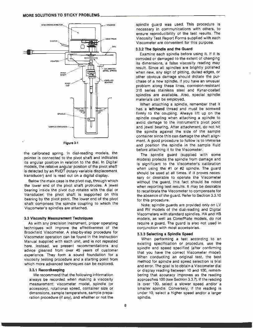
The Viscometer is composed of several mechanical subassemblies. See Figures 3-1 for a schematic view of the major components of a basic dial-reading Viscometer.
The synchronous drive motor and multiple-speed transmission are located at the top of the instrument inside the housing to which the nameplate is attached. The main case of the Viscometer contains a calibrated beryllium-copper spring, one end of which is attached to the pivot shaft; the other end is connected directly to the dial. The dial is driven by the transmission and in turn drives the pivot shaft through
MORE SOLUTIONS TO STICKY PROBLEMS----------------------
SPINDLE
SAMPlE CONl'AINEI•--.J
Figure 3-1
the calibrated spring. In dial-reading models, the pointer is connected to the pivot shaft and indicates its angular position in relation to the dial. In Digital models, the relative angular position of the pivot shaft is detected by an RVDT (rotary variable displacement transducer) and is read out on a digital display.
Below the main case is the pivot cup, through which the lower end of the pivot shaft protrudes. A jewel bearing inside the pivot cup rotates with the dial or transducer; the pivot shaft is supported on this bearing by the pivot point. The lower end of the pivot shaft comprises the spindle coupling to which the Viscometer's spindles are attached.
3.3 Viscosity Measurement Techniques As with any precision instrument, proper operating
techniques will improve the effectiveness of the Brookfield Viscometer. A step-by-step procedure for Viscometer operation can be found in the Instruction Manual supplied with each unit, and is not repeated here. Instead, we present recommendations and advice gleaned from over 45 years of customer experience. They form a sound foundation for a viscosity testing procedure and a starting point from which more advanced techniques can be explored.
3.3.1 Recordkeeping We recommend that the following information
always be recorded when making a viscosity measurement: viscometer model, spindle (or accessory), rotational speed, container size or dimensions, sample temperature, sample preparation procedure (if any), and whether or not the
8
spindle guard was used. This procedure is necessary in communications with others, to ensure reproducibility of the test results. The Viscosity Test Report Forms supplied with each Viscometer are convenient for this purpose.
3.3.2 The Spindle and the Guard Examine each spindle before using it. If it is
corroded or damaged to the extent of changing its dimensions, a false viscosity reading may result. Since all spindles are brightly polished when new, any sign of pitting, dulled edges, or other obvious damage should dictate the purchase of a new spindle. If you have an unusual problem along these lines, corrosion-resistant 316 series stainless steel and Kynar-coated spindles are available. Also, special spindle materials can be employed.
When attaching a spindle, remember that it has a left-hand thread and must be screwed firmly to the coupling. Always lift up on the spindle coupling when attaching a spindle to avoid damage to the instrument's pivot point and jewel bearing. After attachment, do not hit the spindle against the side of the sample container since this can damage the shaft alignment. A good procedure to follow is to immerse and position the spindle in the sample fluid before attaching it to the Viscometer.
The spindle guard (supplied with some models) protects the spindle from damage and is significant to the Viscometer's calibration when using the #1 or #2 spindle. The guard should be used at all times. If it proves necessary or desirable to operate the Viscometer without the guard, this fact should be noted when reporting test results. It may be desirable to recalibrate the Viscometer to compensate for the absence of the guard. Refer to Section 3.3.1 0 for this procedure.
Note: spindle guards are provided only on LV and RV models of the dial-reading and Digital Viscometers with standard spindles. HA and HB models, as well as Cone/Plate models, do not require a guard. The guard is also not used in conjunction with most accessories.
3.3.3 Selecting a Spindle Speed When performing a test according to an
existing specification or procedure, use the spindle and speed specified (after confirming that you have the correct Viscometer model). When conducting an original test , the best method for spindle and speed selection is trial and error. The goal is to obtain a Viscometer dial or display reading between 10 and 100, remembering that accuracy improves as the reading approaches 100 (see Section 3.3.7). If the reading is over 100, select a slower speed and/or a smaller spindle. Conversely, if the reading is under 10, select a higher speed and/or a larger spindle.
---------~rnlffilffillli[R]~lli]] If the approximate viscosity of the sample
fluid is known , a faster method for homing in on the right spindle/speed combination is available by referring to the Factor Finder supplied with the Viscometer. The goal is to select a combi· nation whose range brackets the estimated viscosity of the sample.
For any given spindle/speed combination, the maximum range available is equal to the spindle Factor multiplied by 100. The minimum recommended range equals the Factor multipl ied by 10. For example: a #2 spindle on an LVT Viscometer at 12 RPM has a Factor of 25. The maximum range of this combination is 25 times 100, or 2500 cps. The minimum recommended viscosity that should be measured is 25 times 10, or 250 cps. Therefore, if the viscosity of the sample fluid is estimated to be 4000 cps, another spindle/speed combination must be selected in order to make the measurement. If the sample fluid is around 2000 cps, however, this spindle and speed would be suitable. With a little practice, a quick glance at the Factor Finder will suffice to make an appropriate selection of spindle and speed.
When conducting multiple tests, the same spindle/speed combination should be used for all tests. When a test must be performed at several speeds, select a spindle that produces on-scale readings at all required speeds. This may necessitate using a dial or display reading less than 10, which is acceptable as long as the reduced accuracy of such a reading is recognized .
3.3.4 Sample Container Size For measurements with standard Viscometer
models we recommend a container with an inside diameter of 3 114 inches (83 mm) or larger. The usual vessel for this purpose is a 600 mllow form Griffin beaker. The use of a small container will result in an increase in viscosity readings, particularly with the #1 and #2 spindle.
When utilizing a smaller container, the simplest approach is to report the dimensions of the container and ignore the probable effect on cal ibration. As long as the same size container is used for all subsequent tests, there will be no correlation problem.
Alternatively, the Viscometer can be recalibrated to compensate for the smaller container as outl ined in Section 3.3.10. Also, the use of the Small Sample Adapter should be considered. See Section 2.1.4.
3.3.5 Sample Conditions The sample fluid should be free from
entrapped air. Air can be removed by gently tapping the container on the table top or by using a vacuum apparatus.
The sample should be at constant and
9
uniform temperature. This can be verified by checking the temperature at several different locations within the container. Be sure to bring the sample, spindle, and guard to the same temperature before taking a viscosity reading. Temperature uniformity can often be maintained by agitation prior to a measurement, but first determine that such agitation won 't affect the viscosity of the sample fluid (see Section 4.7.5). The factors used to calculate viscosity values from the Viscometer readings are independent of temperature.
A constant temperature water bath is usually used to maintain the desired temperature. Refer to Section 2.1.3 for information on recommended baths.
High temperature work (up to 300 degrees C) may require the use of the Thermosel accessory. See Section 2.1.6.
Homogeneity of the sample is also quite important, especially in dispersed systems where settling can occur. In many cases, simple stirring just prior to the test will keep the components dispersed. A Brookfield Counter-Rotating Mixer might be useful for this purpose.
3.3.6 Spindle Immersion The spindle should be immersed up to the
middle of the indentation in the shaft. Failure to do so could result in incorrect viscosity readings.
In some cases the sample fluid may change its rheological structure during the act of spindle immersion. To avoid this, we recommend inserting the spindle in a different portion of the sample than the one intended for measurement. The spindle may then be moved horizontally to the center of the sample container. This must be done before attaching the spindle to the Viscometer.
3.3.7 Sensitivity and Accuracy Brookfield Viscometers are guaranteed to be
accurate to within ± 1% of the full-scale range of the spindle/speed combination in use (this percentage, expressed in centipoise values, is equal to the spindle Factor; the accuracy of a spindle/speed combination with a Factor of 25 would therefore be ± 25 cps). Reproducibility is to within ±0.2%.
The accuracy of a particular viscosity reading is dependent upon the actual dial or display reading. In general , the accuracy of the viscosity value will increase as the reading approaches 100. This is because the tolerance of ± 1% of full-scale viscosity applies to all readings, and represents a smaller percentage of measured viscosity as the actual reading increases. Consider the following example:
An LVT Viscometer, when used with a #1 spindle at a speed of 60 RPM, has a spindle Factor of 1 (obtained from the Factor Finder
MORE SOLUTIONS TO STICKY PROBLEMS----------------------
supplied with each instrument). Since the full scale range of any spindle/speed combination is equal to the Factor multiplied by 100, the fullscale viscosity range in this case is 100 cps. The accuracy tolerance is ± 1% of this range, or 1 cps, irrespective of the Viscometer's dial or display reading. Refer to the following table to see how this affects the accuracy of various read ings taken with this spindle/combination:
Viscometer Possible Reading Viscosity Error % Error
100 100 cps 1 cps 1% 50 50 cps 1 cps 2% 10 10 cps 1 cps 10%
The same principle applies to the reproducibility of the read ing. As with accuracy, the potential error introduced by the reproducibility tolerance becomes less significant as the dial or display reading increases.
3.3.8 Obtaining a Viscometer Reading Before operating the Viscometer, be sure that
it is securely attached to its stand and has been properly leveled. Select a spindle and speed combination and attach the spindle to the Viscometer.
Turn the Viscometer on and allow it to run until a constant reading is obtained. Be prepared, however, for some overshoot since momentum gained by the spindle during acceleration may cause the reading to initially oscillate about the final equilibrium value.
A number of procedures can be employed to obtain a satisfactory reading. In some cases, as much as 5 minutes must be allowed for the reading to reach apparent equilibrium. Usually you can just wait until the reading appears relatively constant for a reasonable time.
A more repeatable procedure is to specify a definite number of spindle revolutions to be counted before taking a reading. Since the time requ ired for a certain number of revolutions will differ significantly with the speed in · use, an alternate method is to let the spindle rotate for a specified period of time.
You may find that the reading does not come to an equilibrium value but continues to oscillate. This is usually due to the presence of an elastic as well as a viscous component in the fluid. If the reading continually increases or decreases, the fluid is probably time-dependent and requires special techniques to measure successfully. See Section 4.5.
The display on the Digital Viscometer may fluctuate by 0.1 or 0.2% even after equilibrium is reached. If this happens, simply use the median value as the accepted reading. Larger fluctuations may indicate the conditions described in the preceding paragraph.
Once a valid reading is obtained, multiply it by
10
the Factor for the spindle/speed combination you are using. The Factor will be found on the Factor Finder supplied with the Viscometer.
A note about Factors and Ranges: both can be used to calculate viscosity from a given reading. A Factor (such as that obtained from the Factor Finder) is simply multiplied by the Viscometer reading to calculate viscosity (in centipoise). A Range (as supplied with some Brookfield accessories in lieu of a Factor) is equal to the Factor multiplied by 100. Therefore, to calculate viscosity, first divide the Range by 100, then multiply by the Viscometer dial or display reading.
3.3.9 A Calibration Check People are often concerned about the accu
racy of their Viscometer. Here are some tests of its mechanical performance:
(A) Variations in power frequency will cause the spindle to rotate at an incorrect speed. If you are in an area where electric clocks are . used, this factor may be immediately elimi· nated. Voltage variations have no effect as long as the deviation is not greater than ± 10% of the nameplate voltage and the frequency remains constant.
Other readily apparent symptoms of improper power supply are: failure of the motor to start, jerky spindle rotation, a wildly fluctuating pointer, or inconsistent digital display readings. (B) Damage to the pivot point or jewel bearing will adversely affect the accuracy and repeatability of the Viscometer. The following Oscillation Test will allow you to evaluate the condition of these components:
1. The Viscometer should be mounted and leveled, with no spindle installed and the power switch in the "off" position for Dial Reading Viscometers, and in the "on" position for Digital Viscometers.
2. Turn the spindle coupling to deflect the pointer or digital display upscale from its zero position to a reading of 5 to 10 and let it swing back under its own power.
3. If the pointer swings freely and smoothly, and returns to zero each time this test is repeated, the pivot point and jewel bearing are in good condition. If it crawls back or sticks on the dial, the performance of the Viscometer will not be up to specification, and it should be serviced. On Digital Viscometers the digital display should fluctuate smoothly and return to a zero reading.
(C) We have never found a spring made of beryllium copper which showed any change
---------~rnlmJmJlli~O~[lill in its characteristics due to fatigue, even after hundreds of thousands of flexings. For this reason, a check of the calibrated spring is usually not necessary. There is no external zero adjustment on dial-reading models for the same reason. The zero adjustment on Digital models -is provided to compensate for any possible heat·induced drift in the electronic circuitry.
(D) The use of a calibrated viscosity standard is recommended as a final performance check. Test the viscosity standard as you would any sample fluid , carefully following any applicable instructions.
Brookfield Viscosity Standards (calibrated to within 1 %) are ideal for this test. The use of fluids other than viscosity standards is not recommended due to the probability of unpredictable rheological behavior. (E) If the Viscometer passes all of the preceding tests, its performance should be satisfactory. Should the accuracy or operation of the instrument still be suspect, please refer to the troubleshooting chart in Section 3.5.
3.3.10 Recalibrating the Brookfield Viscometer In many cases it is not practical to use a 600 ml
low form Griffin beaker when making measurements with a Brookfield Viscometer. It may be desirable to use a different container if transferring the material proves messy or timeconsuming . Sometimes people also use the instrument without the guard leg to avoid the extra cleaning that would otherwise be involved. Either of these practices requires that a recalibration of the instrument be made if accurate results are to be obtained.
If measurements have been made under one set of conditions and you merely wish to establish a reference point with the same material under new conditions, the following procedure will suffice:
(1) Measure the material in both. the old and new container and/or with the guard leg removed and in place. Be sure that the same spindle and speed are used and that the temperature of the material remains the same. (2) Note the new reading-this is the new reference point corresponding to the original value. This procedure may be used in establishing
control methods to be followed when the Viscometer is to be used for quality control purposes, and the operator is not concerned with the actual centipoise value of the material.
If your work requires that actual centipoise values be obtained, we suggest the following procedure if a different container is to be used or if you don 't wish to use the guard leg:
11
(1) Following the procedures outlined earlier in this chapter, measure the viscosity of a Newtonian fluid, using a standard container as specified in Section 3.3.4. Brookfield Viscosity Standards are highly recommended for this procedure. Perform this measurement carefully, as the accuracy of your end result depends upon it. Multiply the Viscometer reading by the appropriate Factor to determine the fluid 's viscosity in centipoise. (2) Transfer the Standard to the container for which the Viscometer is to be calibrated. Ensure that the fluid temperature is the same as it was during Step (1). (3) Using the same spindle you intend to use for subsequent sample testing, measure the viscosity of the Standard in the new container. Note the dial or display reading and speed, S1. (4) The new range of measurement is determined by this formula:
R1 = .1QQ.!l X
Where R1 is the full scale range of measurement under the new conditions;
11 is the viscosity of the Standard as measured in step (1); and x is the dial or display reading obtained in step (3).
(5) To calculate the resulting new ranges when the same spindle is operated at different speeds under the new conditions, use this formula:
R1 R2
= S2 S1
Where R1 is the range already established in Step (4) for RPM of S1 , and S2 is the speed for which range R2 is to be determined. (6) The multiplying factor (f) for the new conditions can be determined by this formula:
= B.L 100
Where R1 is the range for the particular spindle and speed combination used, as determined in Step (4) or (5).
To calculate viscos i ty, therefore, multiply the reading obtained on the Viscometer's 0-100 scale by f .
3.4 Viscometer Maintenance Brookfield Viscometers have minimal need for
periodic maintenance. Most problems are readily detected by the Calibration Check in Section 3.3.9. To prevent many problems, a few pointers are worth remembering:
(A) The forces to which the Viscometer responds are extremely small; the optimum performance of the instrument depends on the elimination of all unnecessary friction which
MORE SOLUTIONS TO STICKY PROBLEMS-------- --------- ------
may affect its sensitivity. This means cleanliness. Care must be taken to prevent dust, fumes, liquids, and other forms of contamination from entering the Viscometer housing. If it is necessary to use the instrument in such environments, the use of spindle extensions and/or purge fittings is recommended to minimize the entry of contaminants. More information on these accessories will be found in Section 2.1.10. (B) Never place the instrument upside down with a fluid-coated spindle attached. (C) Do not expose the Viscometer to ambient temperatures in excess of 75 degrees C. When measuring samples at high temperatures the use of spindle extensions or the Thermosel accessory is recommended. (D) Avoid applying side- or down-thrust to the spindle coupling ; this protects the pivot point and jewel bearing, which can be broken or dulled by rough treatment. Always lift the spindle coupling when attaching or removing a spindle. Do not strike the spindle against the sample container or otherwise apply side-thrust to it. Do not pu ll down on the spindle or spindle coupling. (E) Do not drop or severely jar the instrument. The Brookfield Laboratory Stand provides a convenient , sturdy support. If the Viscometer is intended for portable use it should be stored in its carrying case when not in use. If the Viscometer is physically damaged or fails the
Oscil lation Test in Section 3.3.9, it should be returned for repair to Brookfield Engineering Laboratories or to the dealer from whom it was purchased.
The need for periodic preventative maintenance varies with the conditions of use. Under normal circumstances, a yearly service should be sufficient to keep the Viscometer in top working order. More severe use will necessitate more frequent service. The instrument should be returned to Brookfield or one of its dealers for th is service.
3.5 Viscometer Troubleshooting Specif ic fault diagnosis procedures are detailed in
the instruction manual that is provided with each Viscometer. The chart below lists some of the more common problems that you may encounter while using your Viscometer, along with the probable causes and suggested cures. The numbers in parentheses refer to the sections of this book where you will find more information related to the specific problem.
(A) Spindle does not rotate 1. Incorrect power supply
• Check-must match Viscometer requirements (3.3.9)
12
2. Viscometer not plugged in • Connect to appropriate power supply
3. Power switch in " off" position • Turn power switch on
4. Shift knob set " between" speeds • Rotate knob to higher or lower speed
setting (B) Spindle rotates eccentrically
1. Spindle not screwed securely to coupl ing • Tighten
2. Dirt in spindle coupling • Clean
3. Bent spindle • Check other spindles-replace any
that are bent • If all rotate eccentrically-see (8)4
4. Spindle coupling bent • Return to factory or dealer for repair
(C) No dial or display reading 1. Underrange
• Change spindle and/or speed (3.3.3) 2. Spindle jammed
• Consult factory or dealer (D) Dial or display reading over 100
1. Overrange • Change spindle and/or speed (3.3.3)
(E) Viscometer will not return to zero 1. Pivot point or jewel bearing faulty
• Perform calibration check (3.3.9) • Return to factory or dealer for repair
(F) Dial or display reading will not stabilize 1. Check for erratic spindle rotation-may be
caused by incorrect power supply (3.3.9) or mechanical fault
• Return to factory or dealer for repair 2. Bent spindle or spindle coupling
• Check 3. Temperature fluctuation in sample fluid
• See Section 3.3.5 4. Characteristics of sample fluid
• See Section 3.3.8 (G) Inaccurate readings
1. Incorrect spindle/speed selection • See Section 3.3.3
2. Non-standard test parameters • See Section 3.3.10
3. Temperature fluctuations • See Section 3.3.5
4. Incorrect equipment selection • See Chapter 2
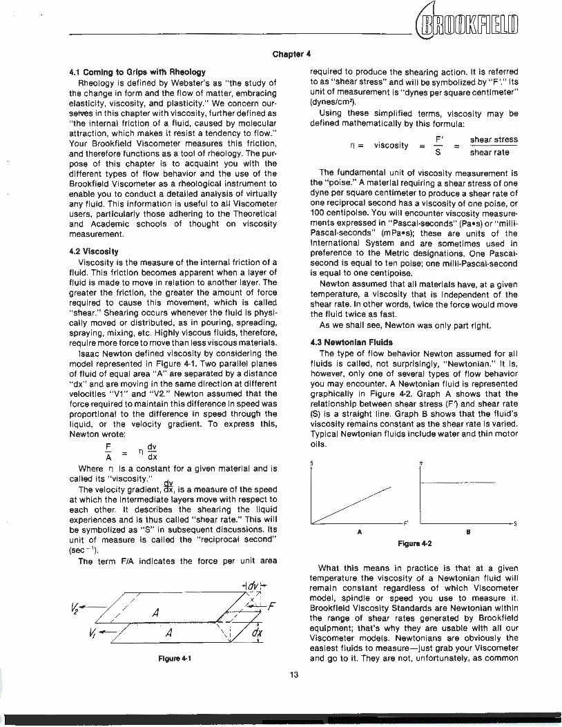
Chapter 4
4.1 Coming to Grips with Rheology Rheology is defined by Webster's as " the study of
the change in form and the flow of matter, embracing elasticity, viscosity, and plasticity." We concern our· selves in this chapter with viscosity, further defined as " the internal friction of a fluid, caused by molecular attraction, which makes it resist a tendency to flow." Your Brookfield Viscometer measures this friction, and therefore functions as a tool of rheology. The pur· pose of this chapter is to acquaint you with the different types of flow behavior and the use of the Brookfield Viscometer as a rheological instrument to enable you to conduct a detailed analysis of virtually any fluid. This information is useful to all Viscometer users, particularly those adhering to the Theoretical and Academic schools of thought on viscosity measurement.
4.2 Viscosity Viscosity is the measure of the internal friction of a
fluid. This friction becomes apparent when a layer of fluid is made to move in relation to another layer. The greater the friction, the greater the amount of force required to cause this movement, which is called " shear." Shearing occurs whenever the fluid is physi· cally moved or distributed, as in pouring, spreading, spraying, mixing, etc. Highly viscous fluids, therefore, require more force to move than less viscous materials.
Isaac Newton defined viscosity by considering the model represented in Figure 4·1. Two parallel planes of fluid of equal area " A" are separated by a distance "dx" and are moving in the same direction at different velocities "V1" and "V2." Newton assumed that the force required to maintain this difference in speed was proportional to the difference in speed through the liquid, or the velocity gradient. To express this, Newton wrote:
F A = 11
dv dx
Where 11 is a constant for a given material and is called its " viscosity."
The velocity gradient , ~. is a measure of the speed at which the intermediate layers move with respect to each other. It describes the shearing the liquid experiences and is thus called " shear rate." This will be symbolized as "S" in subsequent discussions. Its unit of measure is called the " reciprocal second" (sec- 1).
The term F/A indicates the force per unit area
/ v;---/ / / A
A
Figure 4-1
13
required to produce the shearing action. It is referred to as " shear stress" and will be symbolized by " F'." Its unit of measurement is "dynes per square centimeter" (dynes/cm2).
Using these simplified terms, viscosity may be defined mathematically by this formula:
11 = viscosity F'
= s = shear stress
shear rate
The fundamental unit of viscosity measurement is the "poise." A material requiring a shear stress of one dyne per square centimeter to produce a shear rate of one reciprocal second has a viscosity of one poise, or 100 centipoise. You will encounter viscosity measure· ments expressed in "Pascal-seconds" (Pa•s) or " milli· Pascal-seconds" (mPa•s); these are units of the International System and are sometimes used in preference to the Metric designations. One Pascal· second is equal to ten poise; one milli·Pascai·'Second is equal to one centipoise.
Newton assumed that all materials have, at a given temperature, a viscosity that is independent of the shear rate. In other words, twice the force would move the fluid twice as fast.
As we shall see, Newton was only part right.
4.3 NeW1onian Fluids The type of flow behavior Newton assumed for all
fluids is called, not surprisingly, "Newtonian." It is, however, only one of several types of flow behavior you may encounter. A Newtonian fluid is represented graphically in Figure 4·2. Graph A shows that the relationship between shear stress (F1 and shear rate (S) is a straight line. Graph B shows that the fluid 's viscosity remains constant as the shear rate is varied. Typical Newtonian fluids include water and thin motor oils.
s
A B
Flgure4-2
What this means in practice is that at a given temperature the viscosity of a Newtonian fluid will remain constant regardless of which Viscometer model, spindle or speed you use to measure it. Brookfield Viscosity Standards are Newtonian within the range of shear rates generated by Brookfield equipment; that's why they are usable with all our Viscometer models. Newtonians are obviously the easiest fluids to measure-just grab your Viscometer and go to it. They are not, unfortunately, as common
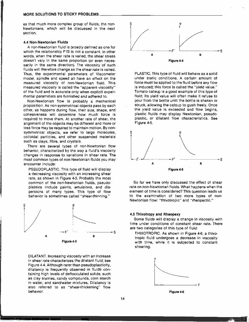
MORE SOLUTIONS TO STICKY PROBLEMS _____________________ _
as that much more complex group of fluids, the non· Newtonians, which will be discussed in the next section.
4.4 Non-Newtonian Fluids A non-Newtonian fluid is broadly defined as one for
which the relationship F'/S is not a constant. In other words, when the shear rate is varied, the shear stress doesn't vary in the same proportion (or even neces· sarily in the same direction). The viscosity of such fluids will therefore change as the shear rate is varied. Thus, the experimental parameters of Viscometer model, spindle and speed all have an effect on the measured viscosity of non-Newtonian fluid. This measured viscosity is called the "apparent viscosity" of the fluid and is accurate only when explicit experi· mental parameters are furnished and adhered to.
Non-Newtonian flow is probably a mechanical proposition. As non-symmetrical objects pass by each other, as happens during flow, their size, shape, and cohesiveness will determine how much force is required to move them. At another rate of shear, the alignment of the objects may be different and more or less force may be required to maintain motion. By non· symmetrical objects, we refer to large molecules, colloidal particles, and other suspended materials such as clays, fibre, and crystals.
There are several types of non-Newtonian flow behavior, characterized by the way a fluid's viscosity changes in response to variations in shear rate. The most common types of non-Newtonian fluids you may encounter include:
PSEUDOPLASTIC. This type of fluid will display a decreasing viscosity with an increasing shear rate, as shown in Figure 4-3. Probably the most common of the non-Newtonian fluids, pseudo· plastics include paints, emulsions, and dis· persions of many types. This type of flow behavior is sometimes called "shear-thinning."
~----------------s A B
Flgure4-3
DILATANT. Increasing viscosity with an increase in shear rate characterizes the dilatant fluid; see Figure 4-4. Although rarer than pseudoplasticity, dilatancy is frequently observed in fluids containing high levels of deflocculated solids, such as clay slurries, candy compounds, corn starch in water, and sand/water mixtures. Dilatancy is also referred to as "shear-thickening" flow behavior.
14
L__ _______ s A B
Flgure4-4
PLASTIC. This type of fluid will behave as a solid under static conditions. A certain amount of force must be applied to the fluid before any flow is induced; this force is called the "yield value." Tomato catsup is a good example of this type of fluid; its yield value will often make it refuse to pour from the bottle until the bottle is shaken or struck, allowing the catsup to gush freely. Once the yield value is exceeded and flow begins, plastic fluids may display Newtonian, pseudo· plastic, or dilatant flow characteristics. See Figure 4·5.
TJ
L__ _ _____ s A B
Flgure4-5
So far we have only discussed the effect of shear rate on non-Newtonian fluids. What happens when the element of time is considered? This question leads us to the examination of two more types of non· Newtonian flow: "thixotropic" and "rheopectic."
4.5 Thixotropy and Rheopexy Some fluids will display a change in viscosity with
time under conditions of constant shear rate. There are two categories of this type of fluid:
THIXOTROPIC. As shown in Figure 4·6, a thixo· tropic fluid undergoes a decrease in viscosity with time, while it is subjected to constant shearing.
1/
L-----------T
Flgure4-8
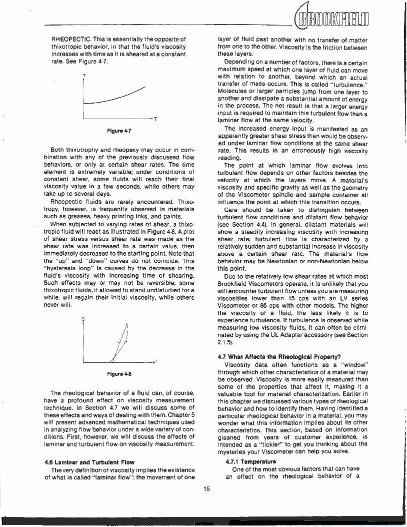
---------~ffimlmJlli[fO~[ill] RHEOPECTIC. This is essentially the opposite of thixotropic behavior, in that the fluid 's viscosity increases with time as it is sheared at a constant rate. See Figure 4-7.
1J
L---------T
Flgure4-7
Both thixotrophy and rheopexy may occur in com· bination with any of the previously discussed flow behaviors, or only at certain shear rates. The time element is extremely variable; under condit ions of constant shear, some fluids will reach their final viscosity value in a few seconds, while others may take up to several days.
Rheopectic fluids are rarely encountered. Thixotropy, however, is frequently observed in materials such as greases, heavy printing inks, and paints.
When subjected to varying rates of shear, a thixotropic fluid will react as illustrated in Figure 4·8. A plot of shear stress versus shear rate was made as the shear rate was increased to a certain value, then immediately decreased to the start ing point. Note that the "up" and "down" curves do not coincide. This "hysteresis loop" is caused by the decrease in the fl uid's viscosity with increasing t ime of shearing. Such effects may or may not be reversible; some th ixotropic fluids, if allowed to stand undisturbed for a while, will regain their init ial viscosity, while others never will .
s
Flgure4-8
The rheological behavior of a fluid can, of course, have a profound effect on viscosity measurement technique. In Section 4.7 we will discuss some of these effects and ways of dealing with them. Chapter 5 will present advanced mathematical techniques used in analyzing flow behavior under a wide variety of con· ditions. First, however, we will discuss the effects of laminar and turbulent flow on viscosity measurement.
4.6 Laminar and Turbulent Flow The very definition of viscosity implies the existence
of what is called " laminar flow": the movement of one
15
layer of fluid past another with no transfer of matter from one to the other. Viscosity is the friction between these layers.
Depending on a number of factors, there is a certain maximum speed at which one layer of fluid can move with relation to another, beyond which an actual transfer of mass occurs. This is called "turbulence." Molecules or larger particles jump from one layer to another and dissipate a substantial amount of energy in the process. The net result is that a larger energy input is required to maintain this turbulent flow than a laminar flow at the same velocity.
The increased energy input is manifested as an apparently greater shear stress than would be observed under laminar flow conditions at the same shear rate. This results in an erroneously high viscosity reading.
The point at which laminar flow evolves into turbulent flow depends on other factors besides the velocity at which the layers move. A material 's viscosity and specific gravity as well as the geometry of the Viscometer spindle and sample container all influence the point at which this transition occurs.
Care should be taken to distinguish between turbulent flow conditions and dilatant flow behavior (see Section 4.4). In general, dilatant materials will show a steadily increasing viscosity with increasing shear rate; turbulent flow is characterized by a relatively sudden and substant ial increase in viscosity above a certain shear rate. The material 's flow behavior may be Newtonian or non-Newtonian below this point.
Due to the relatively low shear rates at which most Brookfield Viscometers operate, it is unlikely that you will encounter turbulent flow unless you are measuring viscosit ies lower than 15 cps with an LV series Viscometer or 85 cps with other models. The higher the viscosity of a fluid, the less likely it is to experience turbulence. If turbulence is observed while measuring low viscosity fluids, it can often be elimi· nated by using the UL Adapter accessory (see Section 2.1 .5).
4.7 What Affects the Rheological Property? Viscosity data often functions as a "window"
through which other characteristics of a material may be observed. Viscosity is more easily measured than some of the properties that affect it, making it a valuable tool for material characterization. Earlier in this chapter we discussed various types of rheolog ical behavior and how to identify them. Having identified a particular rheological behavior in a material , you may wonder what this information implies about its other characteristics. This section, based on information gleaned from years of customer experience, is intended as a "tickler" to get you thinking about the mysteries your VIscometer can help you solve.
4.7.1 Temperature One of the most obvious factors that can have
an effect on the rheolog ical behavior of a
MORE SOLUTIONS TO STICKY PROBLEMS----------------------
material is temperature. Some materials are quite sensitive to temperature, and a relatively small variation will result in a significant change in viscosity. Others are relatively insensitive. Consideration of the effect of temperature on viscosity is essential in the evaluation of materials that will be subjected to temperature variations in use or processing, such as motor oils, greases, and hot-melt adhesives.
4.7.2 Shear Rate Non-Newtonian fluids tend to be the rule
rather than the exception in the real world, making an appreciation of the effects of shear rate a necessity for anyone engaged in the practical application of rheological data. It would, for example, be disastrous to try to pump a dilatant fluid through a system, only to have it go solid inside the pump, bringing the whole process to an abrupt halt. While this is an extreme example, the importance of shear rate effects should not be underestimated.
When a material is to be subjected to a variety of shear rates in processing or use, it is essential to know its viscosity at the projected shear rates. If these are not known, an estimate should be made. Viscosity measurements should then be made at shear rates as close as possible to the estimated values.
It is frequently impossible to approximate projected shear rate values during measurement due to these values falling outside the shear rate range of the Viscometer. In this case it is necessary to make measurements at several shear rates and extrapolate the data to the projected values. This is not the most accurate method for acquiring this information, but it is often the only alternative available, especially when the projected shear rates are very high. In fact, it is always advisable to make viscosity measurements at several shear rates to detect rheological behavior that may have an effect on processing or use. Where shear rate values are unknown or not important, a simple plot of viscosity versus RPM will often suffice.
Examples of materials that are subjected to, and are affected by, wide variations in shear rate during processing and use are: paints, cosmetics, liquid latex, coatings, certain food products, and blood in the human circulatory system.
4.7.3 Measuring Conditions The condition of a material during measure
ment of its viscosity can have a considerable effect on the results of such measurement. It is therefore important to be aware of, and to control as much as possible, the environment of any sample you are testing.
First, the viscosity measurement techniques outlined in Section 3.3 should be adhered to.
16
Variables such as Viscometer model, spindle/ speed combination, sample container size, absence or presence of the guard leg, sample temperature, sample preparation technique, etc., all affect not only the accuracy of your measurements, but the actual viscosity of the material you are measuring.
Second, other, less obvious factors that may affect viscosity must be considered. For example, the sample material may be sensitive to the ambient atmosphere, as is the case with dental impression materials, blast furnace, slag, and blood and mucus. It may be that a controlled atmosphere favorable to the objectives of the test must be provided (see the information on purge fittings in Section 2.1 .10).
Another factor which may affect viscosity measurements is the homogeneity of the sample. It is usually desirable to have a homogeneous sample so that more consistent results may be obtained. Sometimes, however, the tendency of a material to separate into non-homogeneous layers is the characteristic of most interest. Care must be taken in such instances not to disturb that which you wish to study by mixing or shaking the sample.
4.7.4 Time The time elapsed under conditions of shear
obviously affects thixotropic and rheopectic (time-dependent) materials. But changes in the viscosity of many materials can occur over time even though the material is not being sheared. Aging phenomena must be considered when selecting and preparing samples for viscosity measurement. Consider also the fact that many materials will undergo changes in viscosity during the process of a chemical reaction, so that a viscosity measurement made at one point in the reaction may differ significantly from one made at another time.
4.7.5 Previous History What has happened to a sample prior to a
viscosity measurement can significantly affect the result, especially in fluids sensitive to heat or aging. Thus, storage conditions and sample preparation techniques must be designed to minimize their effect on subsequent viscosity tests. Thixotropic materials in particular are sensitive to prior history, as their viscosity will be affected by stirring, mixing, pouring, or any other activity which produces shear in the sample.
4.7.6 Composition and Additives The composition of a material is a determining
factor of its viscosity. When this composition is altered, either by changing the proportions of the component substances, or by the addition of other materials, a change in viscosity is quite likely. For example, the addition of solvent to
printing ink reduces the viscosity of the ink; and additives of many types are used to control the rheological properties of paints.
4.7.7 Special Characteristics of Dispersions and Emulsions ·
Dispersions and emulsions, which are multi· phase materials consisting of one or more solid phases dispersed in a liquid phase, can be affected rheologically by a number of factors. In addition to many of the factors discussed previously, characteristics peculiar to multi· phase materials are also significant to the rheology of such materials. These are discussed below.
One of the major characteristics to study is the state of aggregation of the sample material. Are the particles that make up the solid phase separate and distinct or are they clumped together; how large are the clumps and how tightly are they stuck together? If the clumps (floes) occupy a large volume in the dispersion, the viscosity of the dispersion will tend to be higher than if the floc volume was smaller. This is due to the greater force required to dissipate the solid component of the dispersion.
When floes are aggregated in a dispersion, the reaction of the aggregates to shear can result in shear-thinning (pseudoplastic) flow. At low shear rates, the aggregates may be deformed but remain essentially intact. As the shear rate is increased, the aggregates may be broken down into individual floes, decreasing friction and therefore viscosity. (For more information on pseudoplastic flow, see Section 4.4).
If the bonds within the aggregates are extremely strong, the system may display a yield value (see Section 4.4 about plastic flow). The magnitude of the yield value depends on the force required to break these bonds.
If a material's flocculated structure is destroyed with time as it is sheared, a time·
dependent type of flow behavior will be observed (see Section 4.5).
If the shear rate is decreased after destruction of some or all of the flocculated structure, the material's viscosity may be lower than it previously was at the same shear rate. -Since floes begin to link together after destruction, the rate at which this occurs affects the time required for viscosity to attain previous levels. If the relinking rate is high, viscosity will be about the same as before. If the relinking rate is low, viscosity will be lower. This results in the rheological behavior called "thixotropy" (see Section 4.5).
The attraction between particles in a dispersed phase is largely dependent on the type of material present at the interface between the dis· persed phase and the liquid phase. This in turn affects the rheological behavior of the system. Thus, the introduction of flocculating or deflocculating agents into a system is one method of controlling its rheology.
The shape of the particles making up the dispersed phase is also of significance in determining a system's rheology. Particles suspended in a flowing medium are constantly being rotated. If the particles are essentially spherical, rotation can occur freely. If, however, the particles are needle- or plate-shaped, the ease with which rotation can occur is less predictable, as is the effect of varying shear rates.
The stability of a dispersed phase is particularly critical when measuring the viscosity of a multi phase system. If the dispersed phase has a tendency to settle, producing a non-homogeneous fluid, the rheological characteristics of the system will change. In most cases, this means that the measured viscosity will decrease. Data acquired during such conditions will usually be erroneous, necessitating special precautions to ensure that the dispersed phase remains in suspension.
Chapter 5
5.1 Advanced Methods for Rheological Analysis As mentioned in Chapter 1, those who follow the
Academic school of thought on viscosity measurement have more complex needs than those who follow the Pragmatic or Theoretical schools. They need viscosity data that are defined in rheological terms. This usually requires a complete mathematical description of the Viscometer's operating parameters and an analysis of the rheological behavior of the fluid being studied.
Previous chapters have described various types of fluid behavior and their relation to measurements made with Brookfield Viscometers and accessories.
17
The Appendix details the significant operating parameters of this equipment and presents simplified formulas for obtaining shear rate and shear stress values. However, for many this information is still inadequate to perform the type of analysis they require. Having identified a particular flow behavior and defined it mathematically, these people need more information to understand how the fluid will react in a certain situation, and how to control that reaction. It is for these people that this chapter is provided.
In it you will find the basic formulas from which the simplified shear rate and shear stress information in
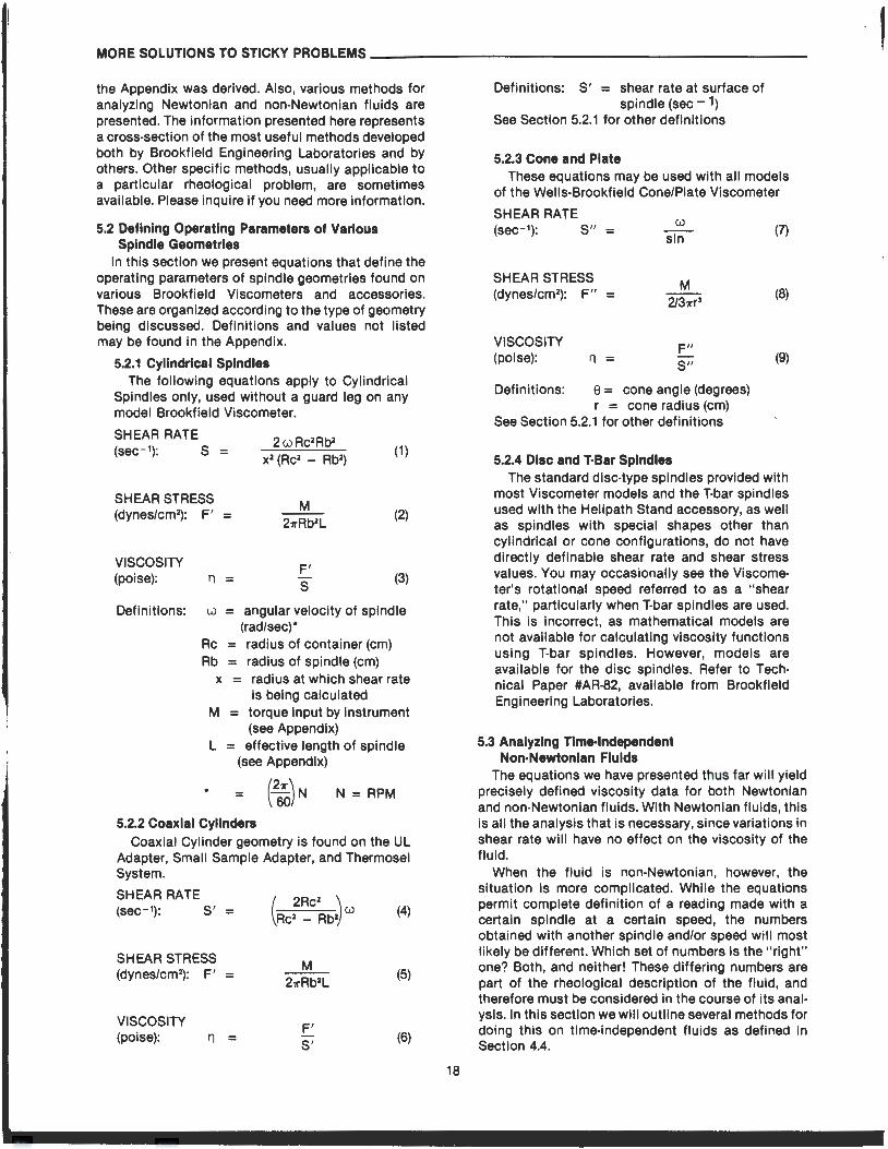
MORE SOLUTIONS TO STICKY PROBLEMS----------------------
the Appendix was derived. Also, various methods for analyzing Newtonian and non-Newtonian fluids are presented. The information presented here represents a cross-section of the most useful methods developed both by Brookfield Engineering Laboratories and by others. Other specific methods, usually applicable to a particular rheological problem, are sometimes available. Please inquire if you need more information.
5.2 Defining Operating Parameters of Various Spindle Geometries
In this section we present equations that define the operating parameters of spindle geometries found on various Brookfield Viscometers and accessories. These are organized according to the type of geometry being discussed. Definitions and values not listed may be found in the Appendix.
5.2.1 Cylindrical Spindles The following equations apply to Cylindrical
Spindles only, used without a guard leg on any model Brookfield Viscometer.
SHEAR RATE (sec- 1): S = 2wRc2Rb2
x2 (Rc2 - Rb2) (1)
SHEAR STRESS (dynes/cm 2): F' = (2)
VISCOSITY (poise): 11 = F'
s (3)
Definitions: w = angular velocity of spindle (rad/sec)*
Rc = radius of container (em) Rb = radius of spindle (em)
•
x = radius at which shear rate is being calculated
M = torque input by instrument (see Appendix)
L = effective length of spindle (see Appendix)
N =RPM
5.2.2 Coaxial Cylinders Coaxial Cylinder geometry is found on the UL
Adapter, Small Sample Adapter, and Thermosel System.
SHEAR RATE (sec- 1): S ' =
SHEAR STRESS (dynes/cm2): F' =
VISCOSITY (poise): '1 =
(4)
M 211'Rb2L
(5)
F' S'
(6)
18
Definitions: S' = shear rate at surface of spindle (sec- 1)
See Section 5.2.1 for other definitions
5.2.3 Cone and Plate These equations may be used with all models
of the Wells-Brookfield Cone/Plate Viscometer
SHEAR RATE (sec- 1): S" =
SHEAR STRESS (dynes/cm2
): F" =
VISCOSITY (poise): 11 =
sin
F" S"
Definitions: 8 = cone angle (degrees) r = cone radius (em)
See Section 5.2.1 for other definitions
5.2.4 Disc and T·Bar Spindles
(7)
(8)
(9)
The standard disc-type spindles provided with most Viscometer models and the T-bar spindles used with the Hellpath Stand accessory, as well as spindles with special shapes other than cylindrical or cone configurations, do not have directly definable shear rate and shear stress values. You may occasionally see the Viscometer's rotational speed referred to as a "shear rate," particularly when T-bar spindles are used. This is incorrect, as mathematical models are not available for calculating viscosity functions using T-bar spindles. However, models are available for the disc spindles. Refer to Technical Paper #AR-82, available from Brookfield Engineering Laboratories.
5.3 Analyzing Tim•lndependent Non-Newtonian Fluids
The equations we have presented thus far will yield precisely defined viscosity data for both Newtonian and non-Newtonian fluids. With Newtonian fluids, this is all the analysis that is necessary, since variations in shear rate will have no effect on the viscosity of the fluid.
When the fluid is non-Newtonian, however, the situation is more complicated. While the equations permit complete definition of a reading made with a certain spindle at a certain speed, the numbers obtained with another spindle and/or speed will most likely be different. Which set of numbers is the "right" one? Both, and neither! These differing numbers are part of the rheological description of the fluid, and therefore must be considered in the course of its analysis. In this section we will outline several methods for doing this on time-independent fluids as defined in Section 4.4.
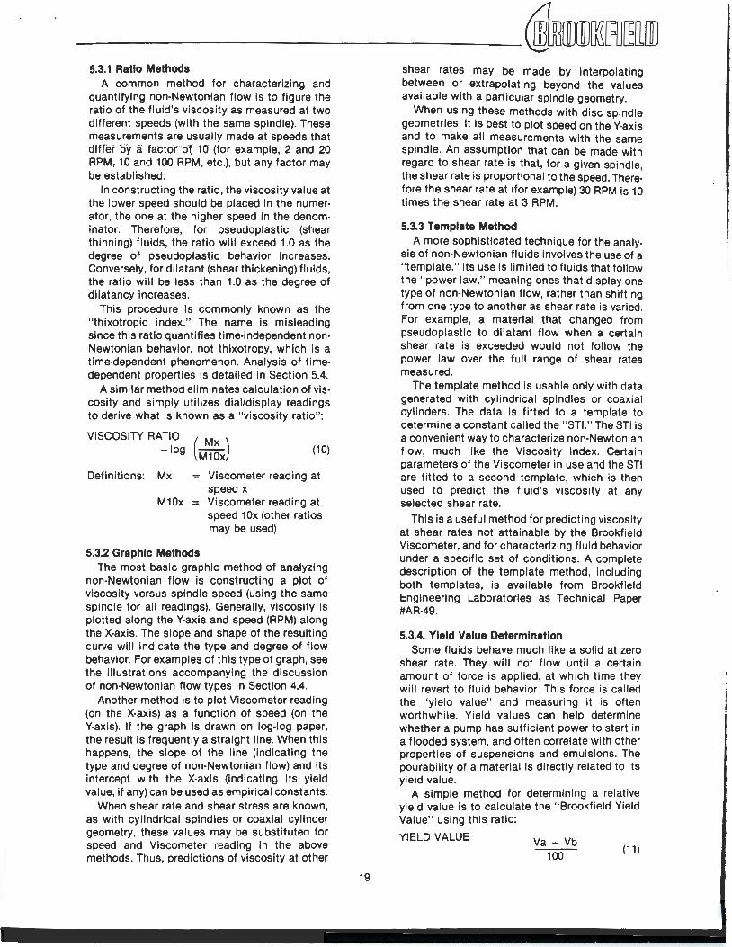
_________ ,[ID[IDffi[RJ~[ill] 5.3.1 Ratio Methods
A common method for characterizing and quantifying non-Newtonian flow is to figure the ratio of the fluid's viscosity as measured at two different speeds (with the same spindle). These measurements are usually made at speeds that differoy·a faCfor- ol 1·0' (for example, 2 and 20 RPM.- .1.0 and 100 RPM, etc.), but any factor may be established.
In constructing the ratio, the viscosity value at the lower speed should be placed in the numerator, the one at the higher speed in the denominator. Therefore, for pseudoplastic (shear thinning) fluids, the ratio will exceed 1.0 as the degree of pseudoplastic behavior increases. Conversely, for dilatant (shear thickening) fluids, the ratio will be less than 1.0 as the degree of dilatancy increases.
This procedure is commonly known as the " thixotropic index." The name is misleading since this ratio quantifies time-independent nonNewtonian behavior, not thixotropy, which is a time-dependent phenomenon. Analysis of timedependent properties is detailed in Section 5.4.
A similar method eliminates calculation of viscosity and simply utilizes dial/display readings to derive what is known as a "viscosity ratio":
VISCOSITY RATIO ·
-log (M~~J (10)
Definitions: Mx = Viscometer reading at speed x
M10x = Viscometer reading at speed 10x (other ratios may be used)
5.3.2 Graphic Methods The most basic graphic method of analyzing
non-Newtonian flow is constructing a plot of viscosity versus spindle speed (using the same spindle for all readings). Generally, viscosity is plotted along the Y-axis and speed (RPM) along the X-axis. The slope and shape of the resulting curve will indicate the type and degree of flow behavior. For examples of this type of graph, see the illustrations accompanying the discussion of non-Newtonian flow types in Section 4.4.
Another method is to plot Viscometer reading (on the X-axis) as a function of speed (on the Y-axis). If the graph is drawn on log-log paper, the result is frequently a straight line. When this happens, the slope of the line (indicating the type and degree of non-Newtonian flow) and its intercept with the X-axis (indicating its yield value, if any) can be used as empirical constants.
When shear rate and shear stress are known, as with cylindrical spindles or coaxial cylinder geometry, these values may be substituted for speed and Viscometer reading in the above methods. Thus, predictions of viscosity at other
19
shear rates may be made by interpolating between or extrapolating beyond the values available with a particular spindle geometry.
When using these methods with disc spindle geometries, it is best to plot speed on the Y-axis and to make all measurements with the same spindle. An assumption that can be made with regard to shear rate is that, for a given spindle, the shear rate is proportional to the speed. Therefore the shear rate at (for example) 30 RPM is 10 times the shear rate at 3 RPM.
5.3.3 Template Method A more sophisticated technique for the analy
sis of non-Newtonian fluids involves the use of a "template." Its use is limited to fluids that follow the "power law," meaning ones that display one type of non-Newtonian flow, rather than shifting from one type to another as shear rate is varied. For example, a material that changed from pseudoplastic to dilatant flow when a certain shear rate is exceeded would not follow the power law over the full range of shear rates measured.
The template method is usable only with data generated with cylindrical spindles or coaxial cylinders. The data is fitted to a template to determine a constant called the "STI." The STI is a convenient way to characterize non-Newtonian flow, much like the Viscosity Index. Certain parameters of the Viscometer in use and the STI are fitted to a second template, which is then used to predict the fluid 's viscosity at any selected shear rate.
This is a useful method for predicting viscosity at shear rates not attainable by the Brookfield Viscometer, and for characterizing fluid behavior under a specific set of conditions. A complete description of the template method, including both templates, is available from Brookfield Engineering Laboratories as Technical Paper #AR-49.
5.3.4. Yield Value Determination Some fluids behave much like a solid at zero
shear rate. They will not flow until a certain amount of force is applied, at which time they will revert to fluid behavior. This force is called the "yield value" and measuring it is often worthwhile. Yield values can help determine whether a pump has sufficient power to start in a flooded system, and often correlate with other properties of suspensions and emulsions. The pourability of a material is directly related to its yield value.
A simple method for determining a relative yield value is to calculate the " Brookfield Yield Value" using this ratio:
YIELD VALUE Va- Vb 100
(11)
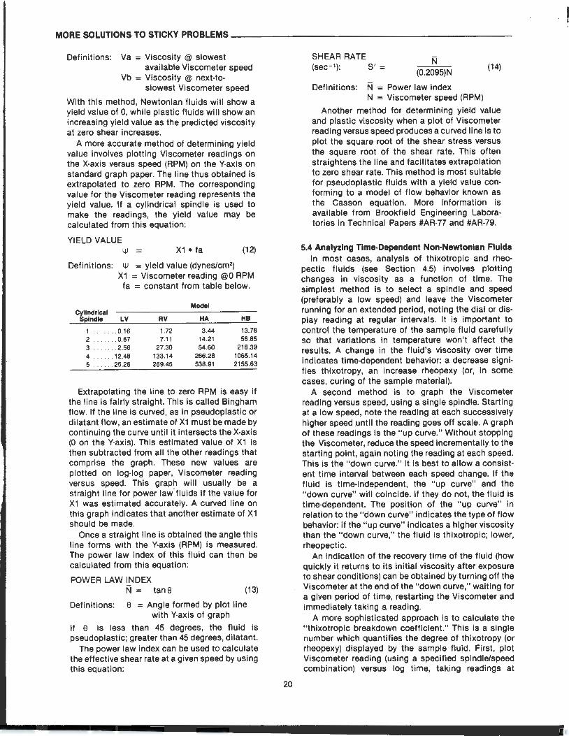
MORE SOLUTIONS TO STICKY PROBLEMS----------------------
Definitions: Va = Viscosity @ slowest available Viscometer speed
Vb = Viscosity @ next-to-slowest Viscometer speed
With this method, Newtonian fluids will show a yield value of 0, while plastic fluids will show an increasing yield value as the predicted viscosity at zero shear increases.
A more accurate method of determining yield value involves plotting Viscometer readings on the X-axis versus speed (RPM) on the Y-axis on standard graph paper. The line thus obtained is extrapolated to zero RPM. The corresponding value for the Viscometer reading represents the yield value. If a cylindrical spindle is used to make the readings, the yield value may be calculated from this equation:
YIELD VALUE ~ = X1 • fa (12)
Definitions: ~ = yield value (dynes/cm2)
X1 = Viscometer reading @0 RPM fa = constant from table below.
Model Cyllndrlc:al S~lndle LV RV HA HB
1 .0.16 1.72 3 .44 13.78 2 ....... 0.67 7.11 14.21 56.85 3 . . 2.56 27.30 54.60 218.39 4 . 12.48 133.14 266.28 1065.14 5 .... .. 25.26 269.45 538.91 2155.63
Extrapolating the line to zero RPM is easy if the line is fairly straight. This is called Bingham flow. If the line is curved, as in pseudoplastic or dilatant flow, an estimate of X1 must be made by continuing the curve until it intersects the X-axis (0 on the Y-axis). This estimated value of X1 is then subtracted from all the other readings that comprise the graph. These new values are plotted on log-log paper, Viscometer reading versus speed. This graph will usually be a straight line for power law· fluids if the value for X1 was estimated accurately. A curved line on this graph indicates that another estimate of X1 should be made.
Once a straight line is obtained the angle this line forms with the Y-axis (RPM) is measured. The power law index of this fluid can then be calculated from this equation:
POWER LAW INDEX N = tans (13)
Definitions: 8 = Angle formed by plot line with Y-axis of graph
If 8 is less than 45 degrees, the fluid is pseudoplastic; greater than 45 degrees, dilatant.
The power law index can be used to calculate the effective shear rate at a given speed by using this equation:
20
SHEAR RATE (sec - 1): S' =
(0.2095)N (14)
Definitions: N = Power law index N = Viscometer speed (RPM)
Another method for determining yield value and plastic viscosity when a plot of Viscometer reading versus speed produces a curved line is to plot the square root of the shear stress versus the square root of the shear rate. This often straightens the line and facilitates extrapolation to zero shear rate. This method is most suitable for pseudoplastic fluids with a yield value conforming to a model of flow behavior known as the Casson equation. More information is available from Brookfield Engineering Laboratories in Technical Papers #AR-77 and #AR-79.
5.4 Analyzing Tlm•Dependent Non-Newtonian Fluids In most cases, analysis of thixotropic and rhea
pectic fluids (see Section 4.5) involves plotting changes in viscosity as a function of time. The simplest method is to select a spindle and speed (preferably a low speed) and leave the Viscometer running for an extended period, noting the dial or display reading at regular intervals. It is important to control the temperature of the sample fluid carefully so that variations in temperature won't affect the results. A change in the fluid's viscosity over time indicates time-dependent behavior: a decrease signifies thixotropy, an increase rheopexy (or, in some cases, curing of the sample material).
A second method is to graph the Viscometer reading versus speed, using a single spindle. Starting at a low speed, note the reading at each successively higher speed .until the reading goes off scale. A graph of these readings is the "up curve." Without stopping the Viscometer, reduce the speed incrementally to the starting point, again noting the reading at each speed. This is the "down curve." It is best to allow a consistent time interval between each speed change. If the fluid is time-independent, the "up curve" and the "down curve" will coincide. If they do not, the fluid is time-dependent. The position of the "up curve" in relation to the "down curve" indicates the type of flow behavior: if the "up curve" indicates a higher viscosity than the "down curve," the fluid is thixotropic; lower, rheopectic.
An indication of the recovery time of the fluid (how quickly it returns to its initial viscosity after exposure to shear conditions) can be obtained by turning off the Viscometer at the end of the "down curve," waiting for a given period of time, restarting the Viscometer and immediately taking a reading.
A more sophisticated approach is to calculate the " thixotropic breakdown coefficient." This is a single number which quantifies the degree of thixotropy (or rheopexy) displayed by the sample fluid. First, plot Viscometer reading (using a specified spindle/speed combination) versus log time, taking readings at
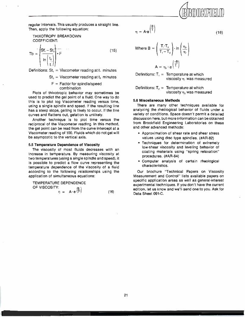
regular intervals. This usually produces a straight line. Then, apply the following equation:
THIXOTROPY BREAKDOWN COEFFICIENT:
-(sr, --st1·--··- ·· -Tb~ ~~(~) •F
(15)
Definitions: St1 = Viscometer reading at t1 minutes
St2 = Viscometer reading at t2 minutes
F = Factor for spindle/speed combination
Plots of thixotropic behavior may sometimes be used to predict the gel point of a fluid. One way to do this is to plot log Viscometer reading versus time, using a single spindle and speed. If the resulting line has a steep slope, gelling is likely to occur. If the line curves and flattens out, gelation is unlikely.
Another technique is to plot time versus the reciprocal of the Viscometer reading. In this method, the gel point can be read from the curve intercept at a Viscometer reading of 100. Fluids which do not gel will be asymptotic to the vertical axis.
5.5 Temperature Dependence of VIscosity The viscosity of most fluids decreases with an
increase in temperature. By measuring viscosity at two temperatures (using a single spindle and speed), it is possible to predict a flow curve representing the temperature dependence of the viscosity of a fluid according to the following relationships using the application of simultaneous equations:
TEMPERATURE DEPENDENCE OF VISCOSITY: (!L)
11 = A· e r· (16)
21
Where B = ( T1~T2 ) · In(~) T1 T2 'TJ1
A= 'TJ1·e{"f)
Definitions: T1 = Temperature at which viscosity 'TJ1 was measured
Definitions: T2 = Temperature at which viscosity 'TJ2 was measured
5.6 Miscellaneous Methods
(16)
There are many other techniques available for analyzing the rheological behavior of fluids under a variety of conditions. Space doesn't permit a detailed discussion here, but more information can be obtained from Brookfield Engineering Laboratories on these and other advanced methods:
• Approximation of shear rate and shear stress values using disc type spindles. (#AR-82)
• Techniques for determination of extremely low-shear viscosity and leveling behavior of coating materials using " spring relaxation" procedures. (#AR-84)
• Computer analysis of certain rheological characteristics.
Our brochure "Technical Papers on Viscosity Measurement and Control;' lists available papers on specific application areas as well as general-interest experimental techniques. If you don't have the current edition, let us know and we'll send one to you. Ask for Data Sheet 091-C.
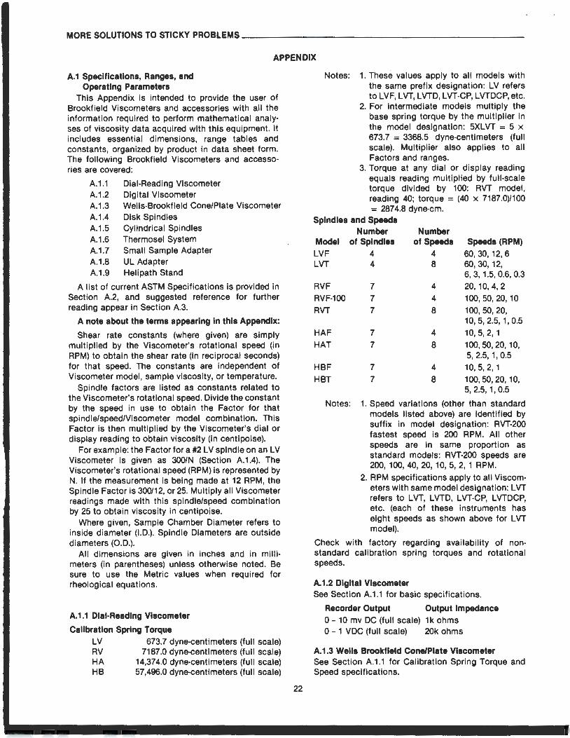
MORE SOLUTIONS TO STICKY PROBLEMS----------------------
APPENDIX
A.1 Specifications, Ranges, and Operating Parameters
This Appendix is intended to provide the user of Brookfield Viscometers and accessories with all the information required to perform mathematical analyses of viscosity data acquired with this equipment. It includes essential dimensions, range tables and constants, organized by product in data sheet form. The following Brookfield Viscometers and accessories are covered:
A.1.1 Dial-Reading Viscometer A.1 .2 Digital Viscometer A.1 .3 Wells-Brookfield Cone/Plate Viscometer A.1.4 Disk Spindles A.1.5 Cylindrical Spindles A.1 .6 Thermosel System A.1.7 Small Sample Adapter A.1.8 UL Adapter A.1.9 Helipath Stand
A list of current ASTM Specifications is provided in Section A.2, and suggested reference for further reading appear in Section A.3.
A note about the terms appearing in this Appendix:
Shear rate constants (where given) are simply multiplied by the Viscometer's rotational speed (in RPM) to obtain the shear rate (in reciprocal seconds) for that speed. The constants are independent of Viscometer model, sample viscosity, or temperature.
Spindle factors are listed as constants related to the Viscometer's rotational speed. Divide the constant by the speed in use to obtain the Factor for that spindle/speed/Viscometer model combination. This Factor is then multiplied by the Viscometer's dial or display reading to obtain viscosity (in centipoise).
For example: the Factor for a #2LV spindle on an LV Viscometer is given as 300/N (Section A.1.4). The Viscometer's rotational speed (RPM) is represented by N. If the measurement is being made at 12 RPM, the Spindle Factor is 300/12, or 25. Multiply all Viscometer readings made with this spindle/speed combination by 25 to obtain viscosity in centipoise.
Where given, Sample Chamber Diameter refers to inside diameter (I.D.). Spindle Diameters are outside diameters (O.D.).
All dimensions are given in inches and in millimeters (in parentheses) unless otherwise noted. Be sure to use the Metric values when required for rheological equations.
A.1.1 Dial-Reading Viscometer
Calibration Spring Torque LV 673.7 dyne-centimeters (full scale) RV 7187.0 dyne-centimeters (full scale) HA 14,374.0 dyne-centimeters (full scale) HB 57,496.0 dyne-centimeters (full scale)
22
Notes: 1. These values apply to ail models with the same prefix designation: LV refers to LVF, LVT, LVTD, LVT-CP, LVTDCP, etc.
2. For intermediate models multiply the base spring torque by the multiplier in the model designation: 5XLVT = 5 x 673.7 = 3368.5 dyne-centimeters (full scale). Multiplier also applies to all Factors and ranges.
3. Torque at any dial or display reading equals reading multiplied by full-scale torque divided by 100: RVT model, reading 40; torque = (40 x 7187.0)/100 = 287 4.8 dyne-em.
Spindles and Speeds Number Number
of Speeds 4
Model LVF LVT
RVF RVF-100 RVT
HAF HAT
of Spindles 4 4
7
7 7
7
7
8
4
4
8
4
8
Speeds (RPM) 60,30, 12,6 60, 30, 12, 6, 3, 1.5, 0.6, 0.3 20, 10,4,2 100,50,20,10 100,50, 20, 10, 5, 2.5, 1, 0.5 10, 5, 2, 1 100, 50, 20, 10, 5, 2.5, 1' 0.5
HBF 7 4 10, 5, 2, 1 HBT 7 8 100,50, 20, 10,
5, 2.5, 1' 0.5
Notes: 1. Speed variations (other than standard models listed above) are identified by suffix in model designation: RVT-200 fastest speed is 200 RPM. All other speeds are in same proportion as standard models: RVT-200 speeds are 200, 100, 40, 20, 10, 5, 2, 1 RPM.
2. RPM specifications apply to all Viscometers with same model designation: LVT refers to LVT, LVTD, LVT-CP, LVTDCP, etc. (each of these instruments has eight speeds as shown above for LVT model).
Check with factory regarding availability of nonstandard calibration spring torques and rotational speeds.
A.1.2 Digital Viscometer See Section A.1.1 for basic specifications.
Recorder Output Output Impedance 0- 10 mv DC (full scale) 1k ohms 0 - 1 VDC (full scale) 20k ohms
A.1.3 Wells Brookfield Cone/Plate Viscometer See Section A.1.1 for Calibration Spring Torque and Speed specifications.
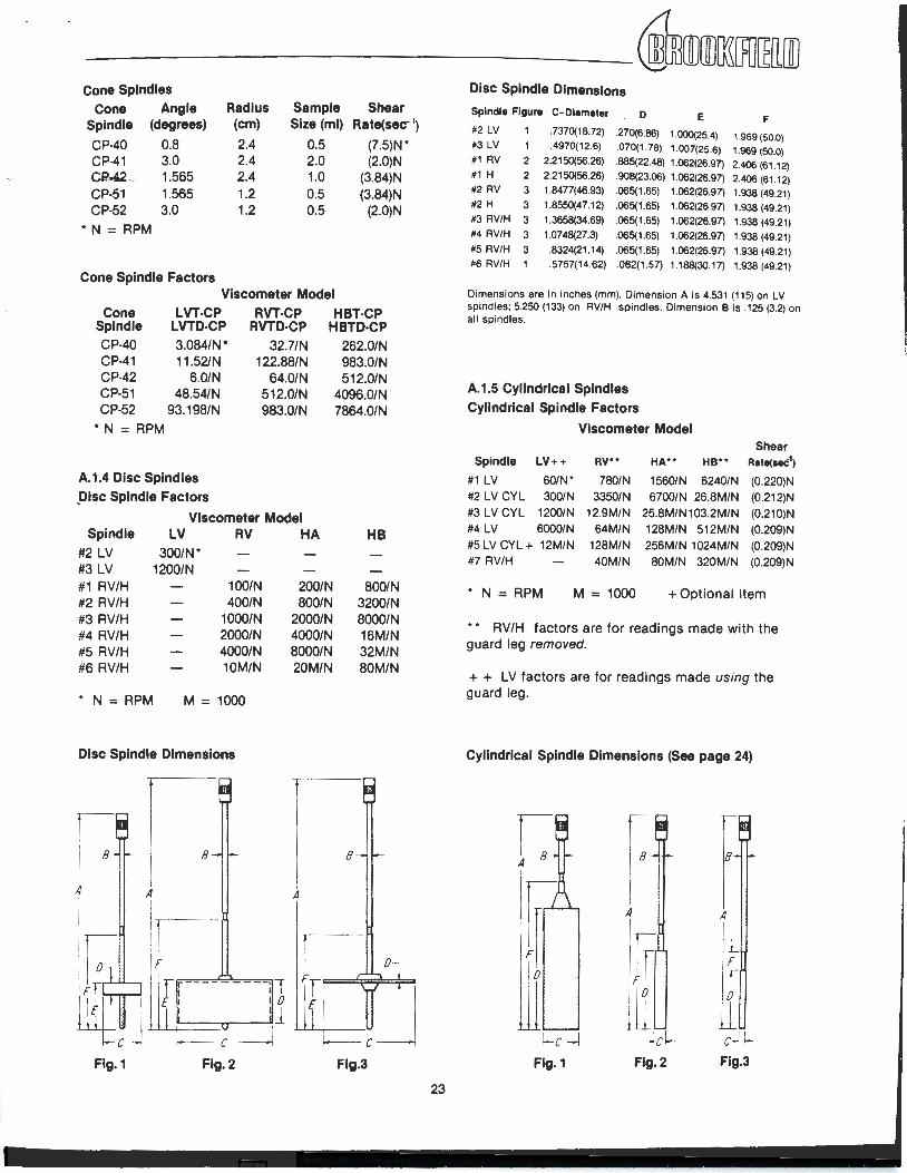
_________ ,[ill[ill~lRJ~[[ID Cone Spindles
Cone Angle Radius Sample Shear Spindle (degrees) (em) Size (ml) Rate(sec-1
)
CP-40 0.8 2.4 0.5 (7.5)N* CP-41 3.0 2.4 2.0 (2.0)N C2.42 ... - 1.56.5 2.4 1.0 (3.84)N CP-51 1.565 1.2 0.5 (3.84)N CP-52 3.0 1.2 0.5 (2.0)N
* N = RPM
Cone Spindle Factors Viscometer Model
Cone LVT-CP RVT-CP HBT-CP Spindle LVTD·CP RVTD·CP HBTD·CP CP-40 CP-41 CP-42 CP-51 CP-52
3.084/N* 11.52/N
6.0/N 48.54/N
93.198/N
32.7/N 122.88/N
64.0/N 512.0/N 983.0/N
* N = RPM
A.1.4 Disc Spindles _Disc Spindle Factors
Viscometer Model Spindle
#2 LV LV RV HA
#3 LV #1 RV/H #2 RV/H #3 RV/H #4 RV/H #5 RV/H #6 RV/H
* N = RPM
300/N* 1200/N
100/N 400/N
1000/N 2000/N 4000/N 10M/N
M = 1000
Disc Spindle Dimensions
8 --
r - 11 E I 0
i '1 .LLL.t=::==u-1 I f----.- c --1
Flg.1 Flg.2
200/N 800/N
2000/N 4000/N 8000/N 20M/N
A
262.0/N 983.0/N 512.0/N
4096.0/N 7864.0/N
8
HB
800/N 3200/N 8000/N 16M/N 32M/N 80M/N
Flg.3
23
Disc Spindle Dimensions
Spindle Flgu111 C-Diameter D E F #2 LV . 7370(18. 72) .270(6.86) 1.000(25.4) 1.969 (50.0) #3 LV 1 .4970(12.6) .070(1 . 78) 1.007(25.6) 1.969 (50.0) #1 RV 2 2.2150(56.26) .885(22.48) 1.062(26.97) 2.406 (61 .12) #1 H 2 2.2150(56.26) .908(23.06) 1.062(26.97) 2.406 (61 .12) #2 RV 3 1.8477(46.93) .065(1 .65) 1.062(26.97) 1.938 (49.21) #2 H 3 1.8550(47.12) .065(1 .65) 1.062(26.97) 1.938 (49.21) #3 RV/H 3 1.3658(34.69) .065(1 .65) 1.062(26.97) 1.938 (49.21) #4 RV/H 3 1.0748(27.3) .065(1 .65) 1.062(26.97) 1.938 (49.21) #5 RV/H 3 .8324(21 .14) .065(1 .65) 1.062(26.97) 1.938 (49.21) #6 RV/H 1 .5757(14.62) .062(1 .57) 1.188(30.17) 1.938 (49.21)
Dimensions are in inches (mm). Dimension A is 4.531 (115) on LV spindles; 5.250 (133) on RV/H spindles. Dimension B is .125 (3.2) on all spindles.
A.1.5 Cylindrical Spindles Cylindrical Spindle Factors
Viscometer Model Shear
Spindle LV++ RV** HA** HB** Rate(see1)
#1 LV 60/N* 780/N 1560/N 6240/N (0.220)N #2 LV CYL 300/N 3350/N 6700/N 26.8M/N (0.212)N #3 LV CYL 1200/N 12.9M/N 25.8M/N103.2M/N (0.210)N #4 LV 6000/N 64M/N 128M/N 512M/N (0.209)N #5 LV CYL + 12M/N 128M/N 256M/N 1024M/N (0.209)N #7 RV/H 40M/N BOM/N 320M/N (0.209)N
* N = RPM M = 1000 +Optional Item
• • RV/H factors are for readings made with the guard leg removed.
+ + LV factors are for readings made using the guard leg.
Cylindrical Spindle Dimensions (See page 24)
0
(....c-1 Fig.1
A
Flg.2
A
L F
r 0
c-HFig.3
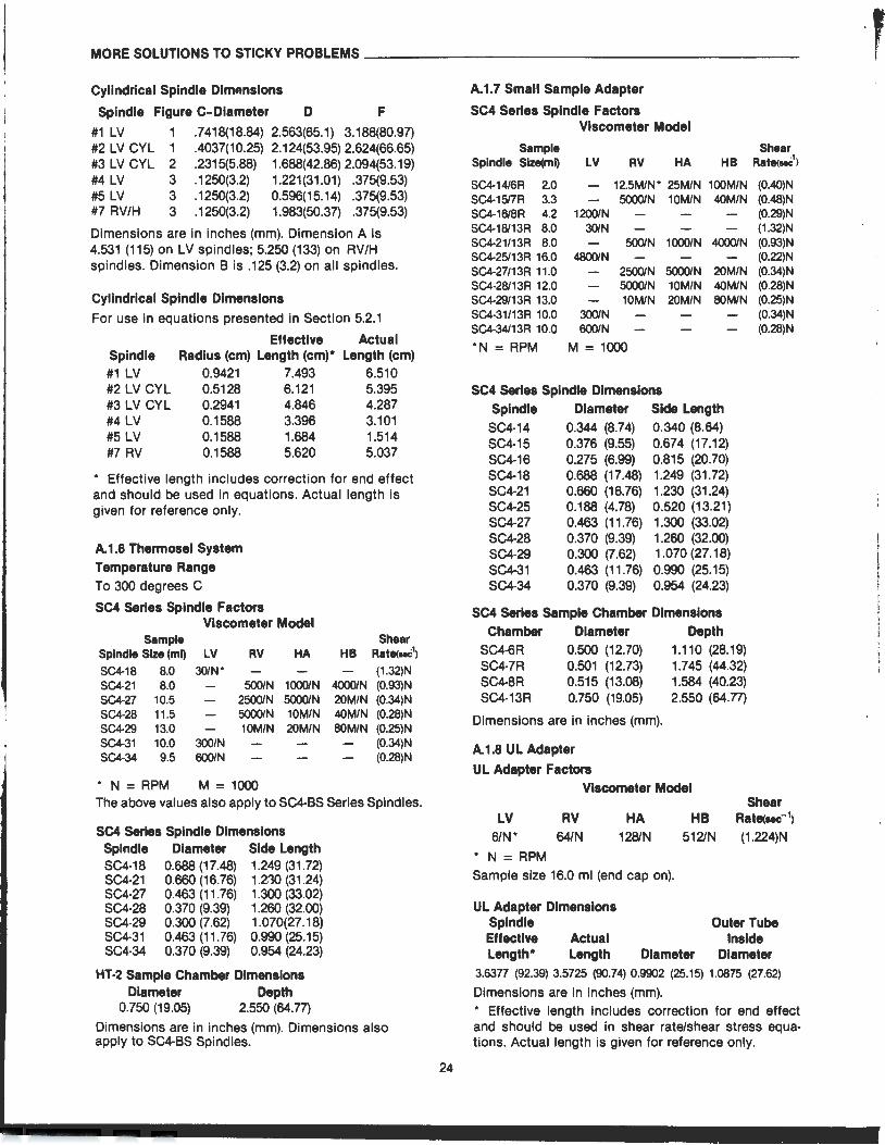
MORE SOLUTIONS TO STICKY PROBLEMS----------------------
Cylindrical Spindle DimAnsions
Spindle Figure C- Diameter D F
#1 LV 1 .7418(18.84) 2.563(65.1) 3.188(80.97) #2 LV CYL 1 .4037(10.25) 2.124(53.95) 2.624(66.65) #3 LV CYL 2 .2315(5.88) 1.688(42.86) 2.094(53.19) #4 LV 3 .1250(3.2) 1.221(31.01) .375(9.53) #5 LV 3 .1250(3.2) 0.596(15.14) .375(9.53) #7 RV/H 3 .1250(3.2) 1.983(50.37) .375(9.53)
Dimensions are in inches (mm). Dimension A is 4.531 (115) on LV spindles; 5.250 (133) on RV/H spindles. Dimension B is .125 (3.2) on all spindles.
Cylindrical Spindle Dimensions
For use in equations presented in Section 5.2.1
Effective Actual Spindle #1 LV
Radius (em) Length (em)* Length (em) 0.9421 7.493 6.510
#2 LV CYL #3 LV CYL #4 LV
0.5128 6.121 5.395 0.2941 4.846 4.287 0.1588 3.396 3.101
#5 LV 0.1588 1.684 1.514 #7 RV 0.1588 5.620 5.037
* Effective length includes correction for end effect and should be used in equations. Actual length is given for reference only.
A.1.6 Thermosel System Temperature Range To 300 degrees C
SC4 Series Spindle Factors Viscometer Model
Sample Spindle Size (ml) LV RV HA SC4·18 8.0 30/N* SC4-21 8.0 500/N 1000/N SC4-27 10.5 2500/N 5000/N SC4-28 11.5 5000/N 10M/N SC4·29 13.0 10M/N 20M/N SC4-31 10.0 300/N SC4·34 9.5 600/N
* N = RPM M = 1000
Shear HB Rate<..C1
)
(1.32)N 4000/N (0.93)N 20M/N (0.34)N 40M/N (0.28)N 80M/N (0.25)N
(0.34)N (0.28)N
The above values also apply to SC4-BS Series Spindles.
SC4 Series Spindle Dimensions Spindle Diameter Side Length SC4-18 0.688 (17.48) 1.249 (31.72) SC4·21 0.660 (16. 76) 1.230 (31.24) SC4·27 0.463 (11.76) 1.300 (33.02) SC4·28 0.370 (9.39) 1.260 (32.00) SC4·29 0.300 (7.62) 1.070(27.18) SC4·31 . 0.463 (11.76) 0.990 (25.15) SC4·34 0.370 (9.39) 0.954 (24.23)
HT-2 Sample Chamber Dimensions Diameter Depth
0.750 (19.05) 2.550 (64.77)
Dimensions are in inches (mm). Dimensions also apply to SC4-BS Spindles.
24
A.1.7 Small Sample Adapter
SC4 Series Spindle Factors VIscometer Model
Sample Spindle Size(ml) LV RV HA HB
SC4-1416R 2.0 12.5M/N* 25M/N 100M/N SC4-1517R 3.3 5000/N 10M/N 40M/N SC4-16/8R 4.2 1200/N SC4-18/13R 8.0 30/N SC4-21/13R 8.0 500/N 1000/N 4000/N SC4-25113R 16.0 4800/N SC4-27/13R 11.0 2500/N 5000/N 20M/N SC4-28/13R 12.0 5000/N 10M/N 40M/N SC4-29/13R 13.0 10M/N 20M/N 80M/N SC4·31/13R 10.0 300/N SC4·34113R 10.0 600/N
*N = RPM M = 1000
SC4 Series Spindle Dimensions Spindle Diameter Side Length SC4-14 0.344 (8.74) 0.340 (8.64) SC4-15 0.376 (9.55) 0.674 (17.12) SC4-16 0.275 (6.99) 0.815 (20.70) SC4·18 0.688 (17.48) 1.249 (31 .72) SC4·21 0.660 (16.76) 1.230 (31.24) SC4·25 0.188 (4.78) 0.520 (13.21) SC4·27 0.463 (11 .76) 1.300 (33.02) SC4·28 0.370 (9.39) 1.260 (32.00) SC4-29 0.300 (7.62) 1.070 (27.18) SC4-31 0.463 (11.76) 0.990 (25.15) SC4-34 0.370 (9.39) 0.954 (24.23)
SC4 Series Sample Chamber Dimensions Chamber Diameter Depth
SC4-6R 0.500 (12.70) 1.110 (28.19) SC4-7R 0.501 (12.73) 1.745 (44.32) SC4-8R 0.515 (13.08) 1.584 (40.23) SC4-13R 0.750 (19.05) 2.550 (64.77)
Dimensions are in inches (mm).
A.1.8 UL Adapter
UL Adapter Factors Viscometer Model
Shear Rate<uch
(0.40)N (0.48)N (0.29)N (1.32)N (0.93)N (0.22)N (0.34)N (0.28)N (0.25)N (0.34)N (0.28)N
Shear LV
6/N* RV HA HB . Rate(sec:-1>
64/N 128/N 512/N . (1.224)N
* N = RPM Sample size 16.0 ml (end cap on).
UL Adapter Dimensions Spindle Outer Tube Effective Actual Inside Length* Length Diameter Diameter
3.6377 (92.39) 3.5725 (90.74) 0.9902 (25.15) 1.0875 (27.62)
Dimensions are in inches (mm). * Effective length includes correction for end effect and should be used in shear rate/shear stress equations. Actual length is given for reference only.
I
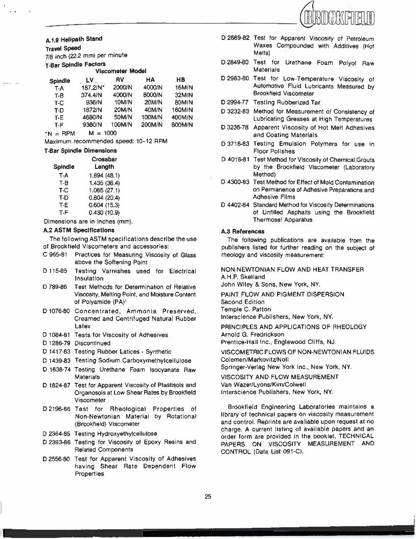
A. 1.9 Hellpath Stand Travel Speed 718 inch (22.2 mm) per minute
T·Bar Spindle Factors VIscometer Model
Spindle _ ·- J,_L. .,----... 8V _ HA T·A 187 .2/N* 2000/N 4000/N T·B 374.4/N 4000/N 8000/N T-C 936/N 1 OM/N 20M/N T·D 1872/N 20M/N 40M/N T-E 4680/N 50M/N 100M/N T-F 9360/N 100M/N 200M/N
*N = RPM M = 1000 Maximum recommended speed: 10-12 RPM
T-Bar Spindle Dimensions
Spindle T·A T·B T-C T·D T-E T·F
Crossbar Length
1.894 (48.1) 1.435 (36.4) 1.065 (27.1) 0.804 (20.4) 0.604 (15.3) 0.430 (10.9)
Dimensions are in inches (mm).
A.2 ASTM Specifications
HB 16M/N 32M/N 80M/N
160M/N 400M/N 800M/N
The following ASTM specifications describe the use of Brookfield Viscometers and accessories: C 965·81 Practices for Measuring Viscosity of Glass
above the Softening Point
D 115-85 Testing Varnishes used for Electrical Insulation
D 789-86 Test Methods for Determination of Relative Viscosity, Melting Point, and Moisture Content of Polyamide (PA)1
D 1076-80 Concentrated, Ammonia Preserved, Creamed and Centrifuged Natural Rubber Latex
D 1084-81 Tests for Viscosity of Adhesives D 1286-79 Discontinued D 1417-83 Testing Rubber Latices - Synthetic
D 1439-83 Testing Sodium Carboxymethylcellulose
D 1638-74 Testing Urethane Foam Isocyanate Raw Materials
D 1824-87 Test for Apparent Viscosity of Plastisols and Organosols at Low Shear Rates by Brookfield Viscometer
D 2196·86 Test for Rheological Properties of Non-Newtonian Material by Rotational (Brookfield) Viscometer
D 2364-85 Testing Hydroxyethylcellulose D 2393-86 Testing for Viscosity of Epoxy Resins and
Related Components
D 2556-80 Test for Apparent Viscosity of Adhesives having Shear Rate Dependent Flow Properties
25
D 2669-82 Test for Apparent Viscosity of Petroleum Waxes Compounded with Additives (Hot Melts)
D 2849-80 Test for Urethane Foam Polyol Raw Materials
D 2983-80 Test for Low-Temperature Viscosity of Automotive Fluid Lubricants Measured by Brookfield Viscometer
D 2994-77 Testing Rubberized Tar
D 3232-83 Method for Measurement of Consistency of Lubricating Greases at High Temperatures
D 3236-78 Apparent Viscosity of Hot Melt Adhesives and Coating Materials
D 3716-83 Testing Emulsion Polymers for use in Floor Polishes
D 4016-81 Test Method for Viscosity of Chemical Grouts by the Brookfield Viscometer (laboratory Method)
D 4300-83 Test Method for Effect of Mold Contamination on Permanence of Adhesive Preparations and Adhesive Films
D 4402-84 Standard Method for Viscosity Determinations of Unfilled Asphalts using the Brookfield Thermosel Apparatus
A.3 References The following publications are available from the
publishers listed for further .reading on the subject of rheology and viscosity measurement:
NON-NEWTONIAN FLOW AND HEAT TRANSFER A.H.P. Skelland John Wiley & Sons, New York, NY.
PAINT FLOW AND PIGMENT DISPERSION Second Edition Temple C. Patton lnterscience Publishers, New York, NY.
PRINCIPLES AND APPLICATIONS OF RHEOLOGY Arnold G. Fredrickson Prentice-Hall Inc., Englewood Cliffs, NJ.
VISCOMETRIC FLOWS OF NON-NEWTONIAN FLUIDS Colemen/Markovitz/Noll Springer-Verlag New York Inc., New York, NY.
VISCOSITY AND FLOW MEASUREMENT Van Wazer/Lyons/Kim/Colwell lnterscience Publishers, New York, NY.
Brookfield Engineering Laboratories maintains a library of technical papers on viscosity measurement and control. Reprints are available upon request at no charge. A current listing of available papers and an order form are provided in the booklet , TECHNICAL PAPERS ON VISCOSITY MEASUREMENT AND CONTROL (Data List 091-C).
1 056·350 1 SM 4192
Ill Ill
measurement The Brookfield
viscometer just naturally lends itself to 8CC8880f'Y use for great versatility in
making viscosity measurements. Whatever
your application, we have an accessory to
help you get accurate, reproducible viscosity
- data quickly and easily.
~ ::write tor catalog. e .... ~, ... . .-===;~
RDDKFIELD SPECIALISTS IN THE MEASUREMENT AND CONTROL OF VISCOSITY
BROOKFIELD ENGINEERING LABORATORIES, INC. 240 Cushing Street, Stoughton, Massachusetts 02072 U.S.A. Phones: (617) 344-4310; 344-4313 Telex: 924497; 200195 Fax: (617) 344·7141 800-628-8139 (US ex MA)
Printed in U.S.A.
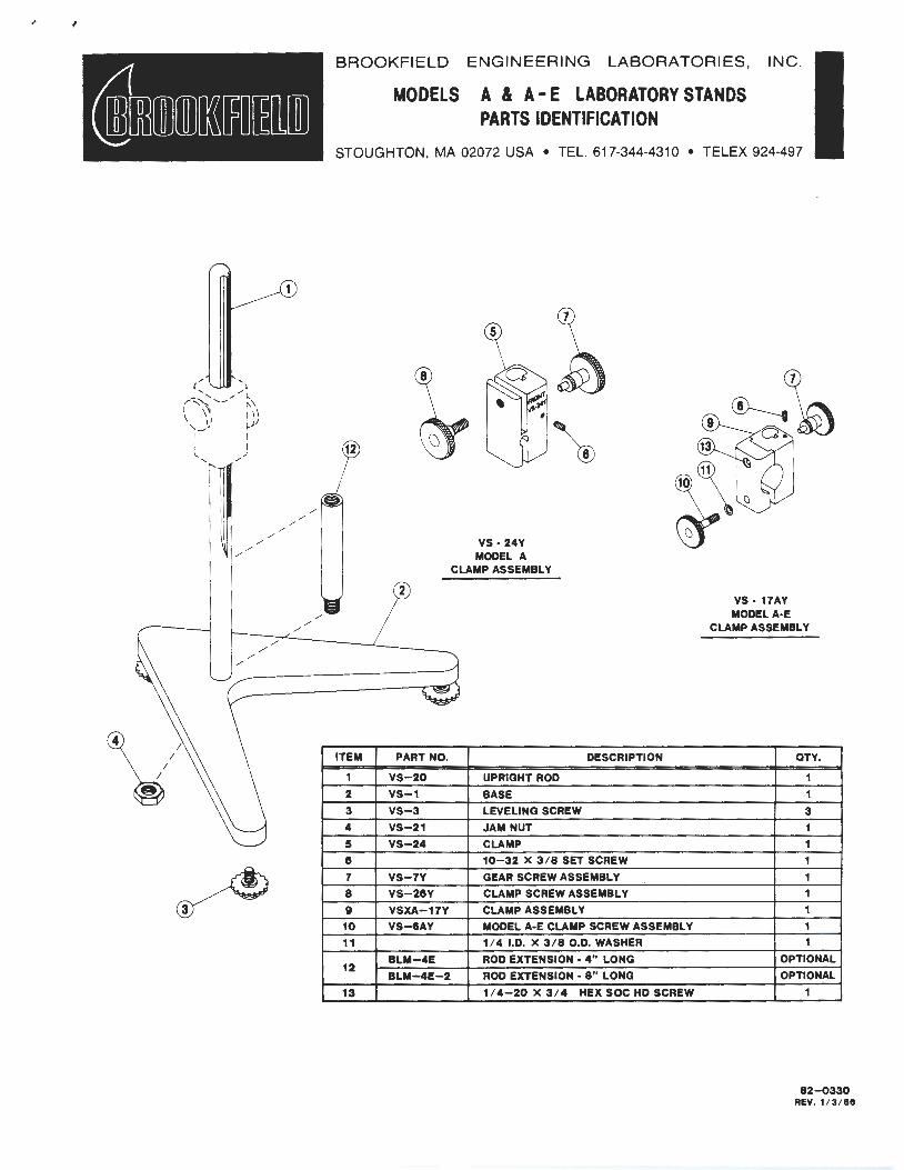
/
\{
/ /
/
~
/
/ /
/
/ /
/
BROOKFIELD ENGINEERING LABORATORIES, INC.
MODELS A & A- E LABORATORY STANDS PARTS IDENTIFICATION
STOUGHTON , MA 02072 USA • TEL. 617-344-4310 • TELEX 924-497
2
ITEM PART NO.
VS-20
2 VS-1
3 VS-3
4 VS-21
5 VS-24
e 7 VS-7Y
8 VS-21SY
9 VSXA-17Y
10 VS-ISAY
11
12 BLM-4E
BLM-4E-2
13
VS- 24Y MODEL A
CLAMP ASSEMBLY
UPRIGHT ROD
BASE
LEVELING SCREW
JAM NUT
CLAMP
DESCRIPTION
10-32 X 3 / 8 SET SCREW
GEAR SCREW ASSEMBLY
CLAMP SCREW ASSEMBLY
CLAMP ASSEMBLY
MODEL A-E CLAMP SCREW ASSEMBLY
1/ 4 I.D. X 3 / 8 O.D. WASHER
ROD EXTENSION - 4" LONG
ROD EXTENSION - 8" LONG
1 / 4-20 X 3/4 HEX SOC HD SCREW
VS- 17AY MODEL A-E
CLAMP ASSEMBLY
OTY.
1
3
OPTIONAL
OPTIONAL
82-Q330 REV. 1/ 3 / 88
MODELS A & A-E LABORATORY STAND INSTRUCTIONS
Unpacking
Check carefully to see that all the components are received with no concealed damage.
1 base 3 leveling screws 1 upright rod
1 jam nut 1 clamp assembly
Remove the three (3) leveling screws from the base and discard the packing material. Remove the jam nut from the upright rod.
Assembly
Screw the leveling screws into the base. Insert the threaded end -of the upright rod into the hole in the top of the base and attach the jam nut to the rod on the underside of the base. With the rod gear rack facing forward (toward the "V" in the base), gently tighten the jam nut. When using the rod extension, screw the threaded end of the upright rod into the extension, then insert the threaded end of the rod extension into the base.
Viscometer Mounting
Dial Vlscometers:
Loosen the Viscometer handle retaining nut (if supplied) and slide it down the power cord. Slide the Viscometer handle (if supplied) toward the cord and remove it from the instrument. Insert the Viscometer handle core into the hole (with the cut-away slot) in the clamp assembly. Adjust the instrument level until the bubble is centered from right to left and tighten the clamp knob (clockwise).
Digital Viscometers:
Insert the Viscometer mounting rod into the hole (with the cut-away slot} in the clamp assembly. Adjust the instrument level until the bubble is centered from right to left and tighten the clamp knob (clockwise). Note: If the Digital Viscometer cannot be leveled, check to insure that the rod is installed with the gear rack facing forward (toward the "V" in the base).
Explosion Proof Viscometers:
Remove the hex socket screw (item 13} from the clamp assembly and separate the clamp. Place the handle of the Viscometer against the clamp/rod assembly and reinstall the clamp and hex socket screw. Adjust the instrument level until the bubble is centered from right to left and tighten the clamp knob (clockwise).
Caution: Do not tighten the clamp knob unless the handle core is inserted in the clamp assembly.
Center the Viscometer relative to the stand base and retighten the jam nut as required. Referring to the Viscometer bubble level, adjust the leveling screws until the instrument is level.
The small screw on the clamp assembly may be loosened or tightened as necessary to provide smooth height adjustment and adequate support for the Viscometer.
82-120-D
~ROOKFIELD BROOKFIELD ENGINEERING LABS., INC. 240 Cushing Street
Stoughton, MA 02072
Date:
~odel: ---------------------------- Serial Number: --------------
To Our Valued Customers:
This Brookfield instrument has been repaired by an authorized Brookfield service technician. While we don't expect this instrument to require service in the near future, we ask that you provide the following information should further service be necessary. This will allow us to service the instrument more quickly and efficiently.
Company: __________________________________________________ ___
Name of Primary User: -----------------------------------
Telephone Number: -----------------------------------------Billing Address: ____________________________________________ _
Shipping Address:-------------------------
Description/Symptoms of Present Problem/Malfunction (please list all):
Length of Time Since Last Serviced (if known): --------------------
Purchase Order Number to Cover Repair:----------------------
Other Comments: -----------------------------------------------
Thank you for your assistance.
Brookfield Engineering Laboratories, Inc. Service Department
Rev. A

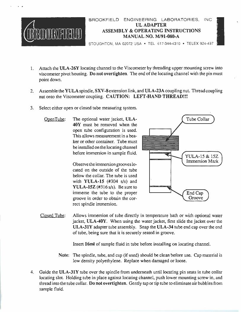
BROOKFIELD ENGINEERING LABORATORIES, INC. ULADAPTER
ASSEMBLY & OPERATING INSTRUCTIONS MANUAL NO. M/91-080-A
STOUGHTON , MA 02072 USA • TEL. 617-344-4310 • TELEX 924-497
1. Attach the ULA-26Y locating channel to the Viscometer by threading upper mounting screw into viscometer pivot housing. Do not overtighten. The end of the l~ating channel with the pin must point down.
2. Assemble the YULA spindle, SXV -8 extension link, and ULA -23A coupling nut. Thread coupling nut onto the Viscometer coupling. CAUTION: LEFT-HAND THREAD!!!
3. Select either open or closed tube measuring system.
OpenTube: The optional water jacket, ULA-40Y must be removed when the open tube configuration is used. This allows measurement in a beaker or other container. Tube must be installed on the locating channel before immersion in sample fluid.
Observe the immersion grooves located on the outside of the tube below the collar. The tube is used with YULA-15 (#304 s/s) and YULA-1SZ (#316 s/s). Be sure to immerse the tube to the proper groove in order to obtain the correct spindle immersion.
Tube Collar
YULA-15 & 15Z Immersion Mark
End Cap Groove
Closed Tube: Allows immersion of tube directly in temperature bath or with optional water jacket, ULA-40Y. When using the water jacket, first slide the jacket over the ULA-31Y adapter tube assembly. Snap the ULA-34 tube end cap over the end of tube, being sure that it is securely seated in groove.
Insert 16ml of sample fluid in tube before installing on locating channel.
Note: The spindle, tube, and cap (if used) should be clean before use. Cap material is low density polyethylene. Replace when damaged or loose.
4. Guide the ULA-31 Y tube over the spindle from underneath until locating pin seats in tube collar locating slot. Holding tube in place against locating channel, push lower mounting screw in, and thread into the tube collar. Do not overtighten. Gently tap or tip tube to eliminate air bubbles from sample fluid.
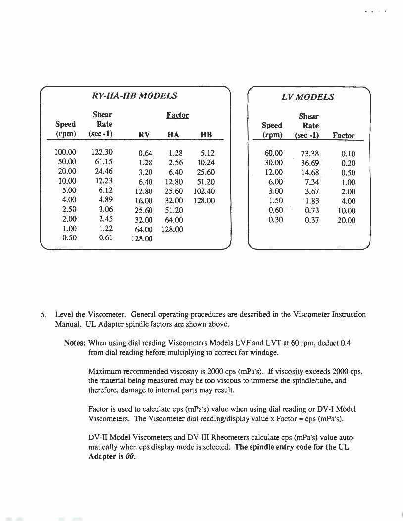
... I.
RV-HA-HB MODELS LV MODELS
Shear Ea~l!!t Shear · Speed Rate Speed Rate . (rpm) (sec -1) RV HA HB (rpm) (sec -1) Factor
100.00 122.30 0.64 1.28 5.12 60.00 73.38 0.10 50.00 61.15 1.28 2.56 10.24 30.00 36.69 · 0.20 20.00 24.46 3.20 6.40 25.60 12.00 14.68 .0.50 10.00 12.23 6.40 12.80 51.20 6~00 7.34 . 1.00
5.00 6.12 12.80 25.60 102.40 3.00. 3.67 2.00 4.00 4.89 16.00 32.00 128.00 1.50 . 1.83 4.00 2.50 3.06 25.60 51.20 0.60 0.73 10.00 2.00 2.45 32.00 64.00 0.30 ·0.37 20.00 1.00 1.22 64.00 128.00 0.50 0.61 128.00
5. Level the Viscometer. General operating procedures are described in the Viscometer Instruction Manual. UL Adapter spindle factors are shown above.
Notes: When using dial reading Viscometers Models L VF and L VT at 60 rpm, deduct 0.4 from dial reading before multiplying to correct for windage.
Maximum recommended viscosity is 2000 cps (mPa"s). If viscosity exceeds 2000 cps, the material being measured may be too viscous to immerse the spindle/tube, and therefore, damage to internal parts may result.
Factor is used to calculate cps (mPa"s) value when using dial reading or DV-1 Model Viscometers. The Viscometer dial reading/display value x Factor =cps (mPa"s).
DV-11 Model Viscometers and DV-111 Rheometers calculate cps (mPa"s) value automatically when cps display mode is selected. The spindle entry code for the UL Adapter is 00.
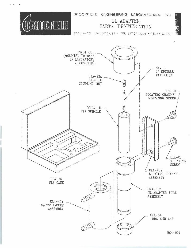
•"' ' ' .
ULA-36 ULA CASE
ULA-40Y WATER JACKET
ASSEMBLY
BROOKFIELD ENGINEERING LABORATORIES, IN C .
UL ADAPTER PARTS IDENTIFICATION
STOUGHTON . ~AA 02072 USA • TEL. 617-344-4310 • TELEX 924-497
PIVOT CUP . (MOUNTED TO BASE
OF LABORATORY VISCOMETER)
ULA-23A SPINDLE ---------~
COUPLING NUT -e
YULA-15 ULA SPINDLE
SXV-8 1" SPINDLE EXTENT! ON
HT-20 LOCATING CHANNEL
MOUNTING SCREW
ULA-26Y
ULA-28 MOUNTING SCREW
LOCATING CHANNEL ASSEMBLY
ULA-31Y UL ADAPTER TUBE ASSEMBLY
ULA-34 TUBE END CAP
BC4-001
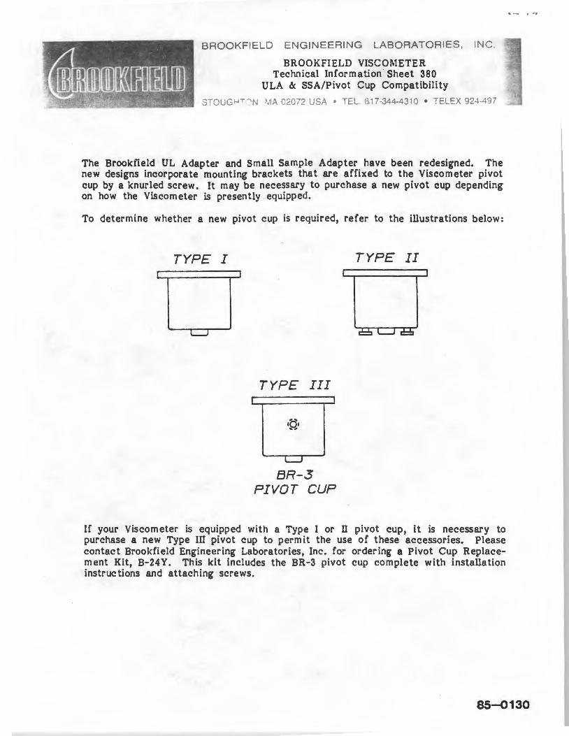
BROOKFIELD ENGINEERING LABORATORIES, INC
BROOKFIELD VISCOMETER Technical Information · Sheet 380
ULA & SSA/Pivot Cup Compatibility
s;ouG__, 7 ;N ·' 1.\ C20~2 'JSA • :E:..... '?' 7-344-4310 • T ELEX 92~-..197
The Brookfield UL Adapter and Small Sample Adapter have been redesigned. The new designs incorporate mounting brackets that are affixed to the Viscometer pivot cup by a knurled screw. It may be necessary to purchase a new pivot cup depending on how the Viscometer is presently equipped.
To determine whether a new pivot cup is required, refer to the illustrations below:
TYPE I
TYPE III
L.....J
BR-3 PIVOT CUP
TYPE II
If your Viscometer is equipped with a Type I or n pivot cup, it is necessary to purchase a new Type III pivot cup to permit the use of these accessories. Please contact Brookfield Engineering Laboratories, Inc. for ordering a Pivot Cup Replacement Kit, B-24Y. This kit includes the BR-3 pivot cup complete with installation instructions and attaching screws.
85-Q130