brother pt-9200dx service manual
TRANSCRIPT

SERVICE MANUAL
MODEL: PT-9200DX

SERVICE MANUAL
MODEL: PT-9200DX

Copyright Brother 2000
All rights reserved.
No part of this publication may be reproduced in anyform or by any means without permission in writing fromthe publisher.
Specifications are subject to change without notice.

PREFACE
This publication is a service manual covering the specifications, theory of operation,disassembly/reassembly procedure, and troubleshooting of the Brother label printer PT-9200DX. It is intendedfor service personnel and other concerned persons to accurately and quickly provide after-saleservice for our PT-9200DX.
To perform appropriate maintenance so that the machine is always in best condition for thecustomer, the service personnel must adequately understand and apply this manual.
This manual is made up of four chapters and an appendix.
CHAPTER I SPECIFICATIONS
CHAPTER II MECHANISMS
CHAPTER III ELECTRONICS
CHAPTER IV TROUBLESHOOTING
APPENDIX CIRCUIT DIAGRAM

CHAPTER I
SPECIFICATIONS

CONTENTS
CHAPTER I SPECIFICATIONS
1.1 MECHANICAL SPECIFICATIONS ................................................................................................ I-1
1.1.1 External View .................................................................................................................. I-1
1.1.2 Input Specifications ......................................................................................................... I-2
1.1.3 Display Specifications...................................................................................................... I-2
1.1.4 Printing Specifications ..................................................................................................... I-2
1.1.5 Tape Cassette Specifications .......................................................................................... I-3
1.1.6 Tape Cutter Specifications............................................................................................... I-3
1.1.7 PC Interface Specifications ............................................................................................. I-3
1.2 ELECTRONIC SPECIFICATIONS................................................................................................. I-4
1.2.1 Power Supply Specifications............................................................................................ I-4

I - 1
1.1 MECHANICAL SPECIFICATIONS
1.1.1 External View
(1) Dimensions (W × D × H) 115 mm × 245 mm × 145 mm
(2) WeightMachine proper Approx. 1.5 kg (only the machine)Machine and package Approx. 3.0 kg
Fig. 1.1-1 External View

I - 2
1.1.2 Input Specifications
(1) Number of keys 2 (ON/OFF ( ) and FEED/CUT ( ) keys)
(2) Key layout See Fig. 1.1-2.
Fig. 1.1-2 Key Layout
1.1.3 Display Specifications
(1) Display method LED (green/red)
1.1.4 Printing Specifications
(1) Printing method Thermal transfer or heat sensitizing methodby thermal headPrinting on plastic tapes (laminated and non-laminated tapes) or special tapes (instantlettering tape, non-laminated thermal filmtape, and fabric printing tape)(Fixed print head and tape feed mechanism)
(2) Printing speed 20 mm/sec
(3) Print headType Thin film thermal head
384 dots × 1 dotDimensions of a heatingelement 0.08 mm wide by 0.0545 mm high
ON/OFF key
FEED/CUT key

I - 3
1.1.5 Tape Cassette Specifications
(1) Cassette Cartridge type
(2) Types of cassettesLaminated tape cassette Laminated tape, ink ribbon, and adhesive
base tapeNon-laminated tapecassette Non-laminated tape and ink ribbonInstant lettering tapecassette Instant lettering tape and ink ribbonFabric printing tapecassette Fabric printing tape and ink ribbonStamp tape cassette Porous-stamp tape and mount
(3) Tape size
Width Length
Laminated tape 6,9,12,18,24,36 mm 8 m(5 m for fluorescent
coating tapes)
Non-laminated tape 6,9,12,18,24 mm 8 m
Instant lettering tape 18 mm 8 m
Fabric printing tape 18 mm 8 m
Stamp tape 18 mm 8 m
1.1.6 Tape Cutter Specifications
(1) Tape cutting method Automatic full cutting method(not user-replaceable)
Automatic half cutting method(not user-replaceable)
1.1.7 PC Interface Specifications
(1) Method* Serial (RS-232C) Baud rate Max. 115.2 Kbps
** USB Standard USB standard Ver.1.1 Full speed
(2) AttachmentsSerial I/F cable Dedicated cableEditor Dedicated editorUSB I/F cable USB standard cable

I - 4
1.2 ELECTRONIC SPECIFICATIONS
1.2.1 Power Supply Specifications
(1) Power supply method
Commercially available power (100V-120V AC, 60 Hz and 220V-240V AC, 50Hz) is input and stabilized to generate DC voltage by the switching regulator inthe machine.
The power supply cord is inserted into an inlet.

CHAPTER II
MECHANISMS

CONTENTS
CHAPTER II MECHANISMS
2.1 THEORY OF MECHANISM OPERATION.................................................................................... II-1
2.1.1 Printing Mechanism........................................................................................................ II-1
2.1.2 Roller Holder Assy Setting and Retracting Mechanism ................................................... II-3
2.1.3 Regular Tape and Ribbon Feed Mechanism ................................................................... II-4
2.1.4 Tape Automatic Full Cutter Mechanism.......................................................................... II-6
2.1.5 Tape Automatic Half Cutter Mechanism ......................................................................... II-7
2.1.6 Forced Tape Eject Mechanism ....................................................................................... II-8
2.1.7 Cover Open Button (Cover Lock Button) ........................................................................ II-9
2.1.8 Cover Open (Cover Lock) Sensor................................................................................... II-9
2.2 DISASSEMBLY AND REASSEMBLY......................................................................................... II-10
2.2.1 Disassembly Procedures .............................................................................................. II-11
[1] Removing the Tape Cassette ................................................................................. II-11
[2] Removing the Cassette Cover................................................................................ II-11
[3] Disassembly of the Cassette Cover Components ................................................... II-12
[4] Removing the Lower Cover.................................................................................... II-13
[5] Removing the Bottom Cover and the Front Cover.................................................. II-14
[6] Removing the Power Supply PCB Assy.................................................................. II-16
[7] Removing the Main PCB Assy and the Mechanical Printing Unit ............................ II-18
[8] Disassembly of the Body Cover ............................................................................. II-20
[9] Removing the Eject Unit Assy, the Half Cutter Assy, the Half Spacer,and the Cutter Assy................................................................................................ II-23
[10] Removing the Half Frame Assy.............................................................................. II-24
[11] Disassembly of the Mechanical Unit ....................................................................... II-26
[12] Disassembly of the Head/Roller Holder Unit ........................................................... II-28

2.2.2 Reassembly Procedures............................................................................................... II-29
[1] Reassembly of the Head/Roller Holder Unit ........................................................... II-29
[2] Reassembly of the Mechanical Unit ....................................................................... II-30
[3] Reassembly of the Half Frame Assy ...................................................................... II-32
[4] Reassembly of the Cutter Assy, the Half Spacer, the Half Cutter Assy,and the Eject Unit Assy .......................................................................................... II-34
[5] Reassembly of the Body Cover .............................................................................. II-35
[6] Reassembly of the Mechanical Printing Unit and the Main PCB assy ..................... II-38
[7] Reassembly of the Power Supply PCB Assy .......................................................... II-41
[8] Reassembly of the Covers ..................................................................................... II-44
[9] Reassembly of the Cassette Cover Components.................................................... II-47
[10] Reassembly of the Cassette Cover ........................................................................ II-48
[11] Reassembly of the Tape Cassette.......................................................................... II-48
[12] Test Printing and Operation Check......................................................................... II-49
[13] Error Code ............................................................................................................. II-50
[14] Error Message........................................................................................................ II-51

II - 1
2.1 THEORY OF MECHANISM OPERATION
2.1.1 Printing Mechanism
(1) Construction of thermal head
This machine uses thermal transfer printing. The thermal head contains 384heating elements vertically arranged. The size of one heating element is0.08 mm wide by 0.0545 mm high, as shown in Fig. 2.1-1.
Fig. 2.1-1 Heating Elements of the Thermal Head
(2) Theory of printing
During printing operation, the cylindrical rubber platen crimps the tape* and theink ribbon** on the thermal head. At this time, the CPU selects the requiredheating elements out of the 384 heating elements to energize them. Thetheory of printing depends on the use of non-laminated thermal film tapecassettes or other tape cassettes:
(*) Laminated tape when using laminated tape cassettes.Non-laminated tape when using non-laminated tape cassettes.Instant lettering tape when using instant lettering tape cassettes.Fabric printing tape when using fabric printing tape cassettes.Stamp tape when using stamp tape cassettes.
(**) When using non-laminated thermal film tape cassettes, no ink ribbon ispresent.

II - 2
[For non-laminated thermal film tape cassettes]
If the selected heating element(s) generates heat, the thermal film tapedevelops itself to produce a dot on the tape. The tape is advanced and thenext printing cycle is repeated, thus forming a character and graphics on thetape.When using laminated tape cassettes, instant lettering tape cassettes, or fabricprinting tape cassettes, print data is processed so that a character andgraphics read correctly when viewed from the opposite side of the printingsurface of the tape. (In other words, the mirror image of the character andgraphics is printed.)
[For stamp tape cassettes]
If the selected heating element(s) generates heat, the porous-stamp tape willbe melted so that a pore(s) will be formed in the tape. The tape is advancedand the next heating cycle is repeated, thus forming a character of pores in thetape. The printed stamp tape can be used as the face of a stamp. When thestamp is pressed against the ink-pad, it will absorb ink through the pores.
(3) Character Formation
While the main motor (stepping motor) feeds the tape and ink ribbon (tape onlywhen using non-laminated thermal film tape cassettes or stamp tapecassettes) by 0.0705 mm for 3.5 ms, the thermal head generates heat once.The feed amount of 0.0705 mm is smaller than the width (0.08 mm) of theheating elements so that the heat generated at one heating cycle will overlapwith the next heating cycle. This forms a character having no gap betweenadjacent printed dots.

II - 3
2.1.2 Roller Holder Assy Setting and Retracting Mechanism
This mechanism consists of the release cam, roller release rod, and rollerholder/head assy.
The roller holder assy incorporates the platen holder and the sub roller holder.These holders support the platen and the tape feed sub roller so that they canmove perpendicularly to the thermal head and the tape feed roller, respectively.
The platen is pressed perpendicularly against the thermal head under a uniformload regardless of the thickness of the tape, so that the tape is fed.
Closing the cassette cover pushes down the release cam which moves the rollerrelease rod to the left (when viewed from the front of the machine). This pivots theroller holder assy around the shaft secured on the thermal head assy so as to pressthe roller holder assy against the thermal head.
The platen is pressed perpendicularly against the thermal head with the tape andink ribbon (only the tape when using non-laminated thermal film tape cassettes orstamp tape cassettes) sandwiched inbetween under a uniform load by the platenspring.
At the same time, the platen gear becomes engaged with the platen idle gear.
Also, the tape feed sub roller is pressed perpendicularly against the tape feed rollerbuilt in the tape cassette with the tape (and base paper when using laminated tapecassettes or stamp tape cassettes) sandwiched inbetween under a uniform load bythe sub roller holder springs. At the same time, the sub roller gear becomesengaged with the tape feed gear.
Opening the cassette cover causes the release lever spring to slide the rollerrelease rod in the direction of the arrow. This retracts the roller holder assy from thethermal head, providing you with enough space to replace the tape cassette.
Fig. 2.1-2 Roller Holder Assy Setting and Retracting Mechanism
Tape cassette
Platen idle gear
Tape feed roller
Adhesive base tape
Platen roller
Tape feed sub roller
Roller holder assyRoller release rod Thermal head assy
Roller holder shaftRelease cam
Ink ribbon
Laminated tape
Platen gear Platen roller
Platen spring
Sub roller springRoller holder
Sub roller gear
Sub roller
II - 4
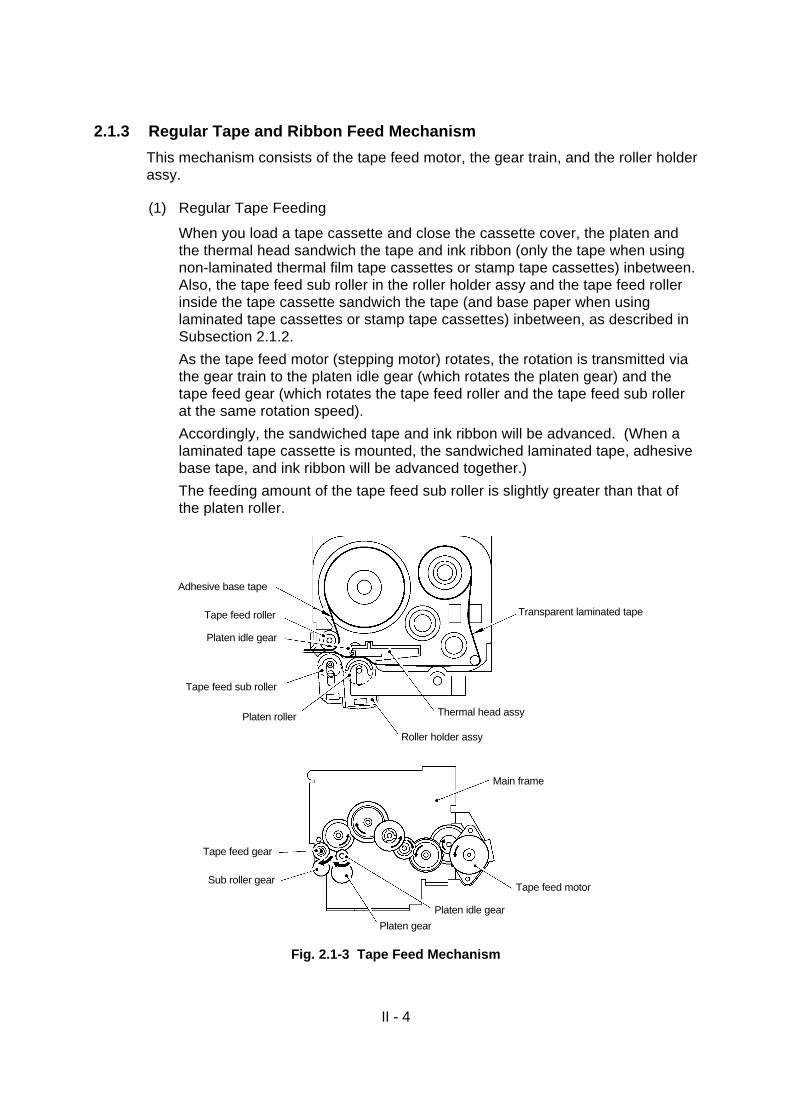
2.1.3 Regular Tape and Ribbon Feed Mechanism
This mechanism consists of the tape feed motor, the gear train, and the roller holderassy.
(1) Regular Tape Feeding
When you load a tape cassette and close the cassette cover, the platen andthe thermal head sandwich the tape and ink ribbon (only the tape when usingnon-laminated thermal film tape cassettes or stamp tape cassettes) inbetween.Also, the tape feed sub roller in the roller holder assy and the tape feed rollerinside the tape cassette sandwich the tape (and base paper when usinglaminated tape cassettes or stamp tape cassettes) inbetween, as described inSubsection 2.1.2.
As the tape feed motor (stepping motor) rotates, the rotation is transmitted viathe gear train to the platen idle gear (which rotates the platen gear) and thetape feed gear (which rotates the tape feed roller and the tape feed sub rollerat the same rotation speed).
Accordingly, the sandwiched tape and ink ribbon will be advanced. (When alaminated tape cassette is mounted, the sandwiched laminated tape, adhesivebase tape, and ink ribbon will be advanced together.)
The feeding amount of the tape feed sub roller is slightly greater than that ofthe platen roller.
Fig. 2.1-3 Tape Feed Mechanism
Adhesive base tape
Tape feed roller
Platen idle gear
Tape feed sub roller
Platen roller
Roller holder assy
Thermal head assy
Transparent laminated tape
Tape feed gear
Sub roller gear
Platen gear
Platen idle gear
Tape feed motor
Main frame

II - 5
(2) Adhesive Base Tape Feeding (only for laminated tape cassettes)
A laminated tape cassette contains both a transparent laminated tape roll anda separate adhesive base tape roll.
When a transparent laminated tape and an adhesive base tape pass throughthe contact point (between the tape feed roller and tape feed sub roller), theyare then bonded together into a single, printed tape. The ink printed on thelaminated tape is, therefore, sealed up with the adhesive base tape.
(3) Ink Ribbon Feeding (except for non-laminated thermal film tape cassettes andstamp tape cassettes)
As the main motor rotates, the ribbon drive cam located at the middle of thegear train rotates counterclockwise. When fitted on the ribbon drive cam, theribbon take-up roll in the tape cassette also rotates to take up the ink ribbon.
To apply proper tension to the ink ribbon between the platen roller and theribbon drive cam, the feed amount of the ribbon drive cam is slightly greaterthan that of the tape feed gear. The difference between the feed speeds atthe platen roller and at the ribbon drive cam is absorbed by the clutch springwhich is integrated in the ribbon drive cam and allows the cam to slip.
This way, the ink ribbon is kept tense, which enables the ribbon to clearlyseparate from the tape at the stabilized angle after printing.
Fig. 2.1-4 Ribbon Feed Mechanism
Tape feed roller
Tape feed sub roller
Platen roller
Roller holder assy
Thermal head assyInk ribbon
Ribbon take-up roll
Main frameTape feed motor
Ribbon drive cam

II - 6
2.1.4 Tape Automatic Full Cutter Mechanism
The tape automatic full cutter mechanism consists of a stationary blade and amovable blade driven by the full cutter motor.
Upon completion of printing and tape feeding, the CPU activates the full cuttermotor (DC motor) whose clockwise rotation is transmitted to the cutter helical gear.
As the cutter helical gear rotates counterclockwise, its boss “A” (which is fitted in theopening of the movable blade) actuates the movable blade to pivot it around shaft“B”. Consequently, the cutter cuts the printed tape routing through the movable andstationary blades, just like a pair of scissors.
Subsequently, the CPU keeps the full cutter motor on. When the movable bladereturns to the home position, part “C” of the cutter helical gear presses the full cuttersensor switch secured on the half frame. The moment the CPU receives the sensorsignal, it stops the full cutter motor.
Fig. 2.1-5 Tape Automatic Full Cutter Mechanism
Full cutter sensor
Cutter helical gear
“C”
Stationary blade
“B”
“A” Cutter helical gear
Full cutter motor assy
Movable blade
II - 7
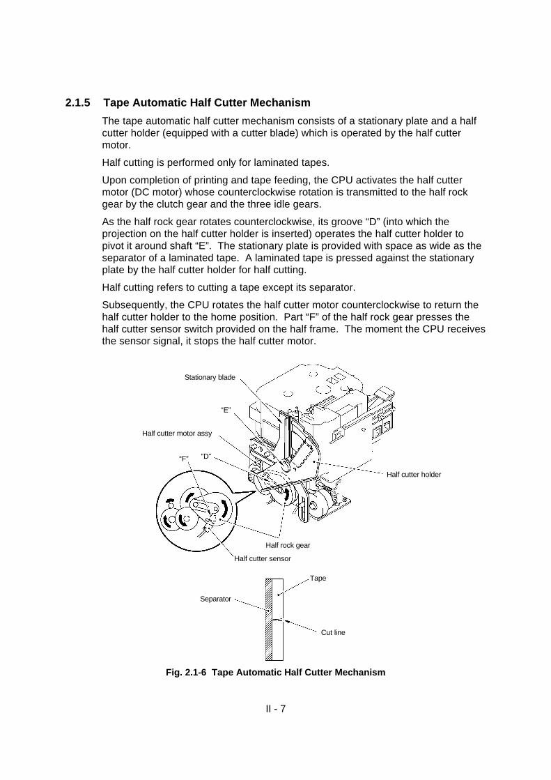
2.1.5 Tape Automatic Half Cutter Mechanism
The tape automatic half cutter mechanism consists of a stationary plate and a halfcutter holder (equipped with a cutter blade) which is operated by the half cuttermotor.
Half cutting is performed only for laminated tapes.
Upon completion of printing and tape feeding, the CPU activates the half cuttermotor (DC motor) whose counterclockwise rotation is transmitted to the half rockgear by the clutch gear and the three idle gears.
As the half rock gear rotates counterclockwise, its groove “D” (into which theprojection on the half cutter holder is inserted) operates the half cutter holder topivot it around shaft “E”. The stationary plate is provided with space as wide as theseparator of a laminated tape. A laminated tape is pressed against the stationaryplate by the half cutter holder for half cutting.
Half cutting refers to cutting a tape except its separator.
Subsequently, the CPU rotates the half cutter motor counterclockwise to return thehalf cutter holder to the home position. Part “F” of the half rock gear presses thehalf cutter sensor switch provided on the half frame. The moment the CPU receivesthe sensor signal, it stops the half cutter motor.
Fig. 2.1-6 Tape Automatic Half Cutter Mechanism
Half cutter sensor
Half rock gear
Half cutter holder
“F” “D”
Half cutter motor assy
“E”
Stationary blade
Tape
Separator
Cut line
II - 8
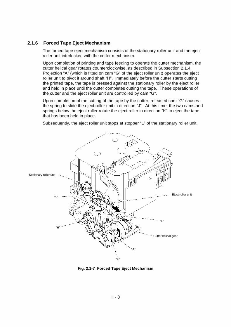
2.1.6 Forced Tape Eject Mechanism
The forced tape eject mechanism consists of the stationary roller unit and the ejectroller unit interlocked with the cutter mechanism.
Upon completion of printing and tape feeding to operate the cutter mechanism, thecutter helical gear rotates counterclockwise, as described in Subsection 2.1.4.Projection “A” (which is fitted on cam “G” of the eject roller unit) operates the ejectroller unit to pivot it around shaft “H”. Immediately before the cutter starts cuttingthe printed tape, the tape is pressed against the stationary roller by the eject rollerand held in place until the cutter completes cutting the tape. These operations ofthe cutter and the eject roller unit are controlled by cam “G”.
Upon completion of the cutting of the tape by the cutter, released cam “G” causesthe spring to slide the eject roller unit in direction “J”. At this time, the two cams andsprings below the eject roller rotate the eject roller in direction “K” to eject the tapethat has been held in place.
Subsequently, the eject roller unit stops at stopper “L” of the stationary roller unit.
Fig. 2.1-7 Forced Tape Eject Mechanism
Stationary roller unit
“K”
“H”
“A”
Cutter helical gear
“L”
“G”
Eject roller unit
“J”

II - 9
2.1.7 Cover Open Button (Cover Lock Button)
Pressing the cover open button (cover lock button) slides the cover button actuatorto the left. This presses the cover lock actuator of the cassette cover, releasing thehook to open the cassette cover.
Fig. 2.1-8 Cover Open Button
2.1.8 Cover Open (Cover Lock) Sensor
The cover open (cover lock) sensor (push switch) is provided on the cassettesensor PCB. Closing the cassette cover puts its sensor tab on the cover open(cover lock) sensor (push switch), signaling that the cassette cover is closed.
Fig. 2.1-9 Cover Open Sensor
Cover lock actuator
Cover button actuator
Cover open button(Cover lock button)
Cassette sensor PCB
Cover open switch(push switch)
Sensor tab
Cassette cover

II - 10
2.2 DISASSEMBLY AND REASSEMBLY
Precautions on Safety
(1) Disassemble and reassemble the machine on a grounded antistatic sheet.Touching electronic components such as an LSI with an electrified hand willbreak them, as they are easily affected by static electricity.
(2) Wrap the machine in an electrically conductive aluminum sheet before carryingit.
(3) When using heating tools such as soldering iron, take care not to thermallybreak resin components such as a wire, a PCB, and a cover.
(4) Take care not to lose small components, such as a screw and a washer, whichhave been removed to replace other components.
(5) Tighten screws according to the list of tightening torque below.
List of Tightening Torque
Position Screw Qty. Tightening torque [kgf·cm]
Head/roller holder unit Screw, pan (S/P washer) M3×10 2 59±10 N·cm (6±1 kgf·cm)
Eject unit Screw, pan (S/P washer) M4×12 2 88±10 N·cm (9±1 kgf·cm)
Half frame Screw, pan (S/P washer) M3×6 2 59±10 N·cm (6±1 kgf·cm)
Tape feed motor Screw, pan M2.6×3.5 2 39±10 N·cm (4±1 kgf·cm)
Full cutter motor 2
Half cutter motor 2
Full cutter sensor Screw, pan M1.7×6 1 15±5 N·cm (1.5±0.5 kgf·cm)
Half cutter sensor 1
Main frame Taptite, bind B M2.6×8 2 39±10 N·cm (4±1 kgf·cm)
Tape end sensor 2
Main PCB 3
Cassette cover bracket 2
Sub PCB 2
Inlet bracket 2
Power supply PCB 2
Bottom cover Taptite, bind B M2.6×10 3 39±10 N·cm (4±1 kgf·cm)
Lower cover 1
Inlet Screw, flat B M3×10 2 39±10 N·cm (4±1 kgf·cm)
Shield plate B Screw, pan (S/P washer) M4×8 1 59±10 N·cm (6±1 kgf·cm)
Ground wire 1
II - 11
2.2.1 Disassembly Procedures
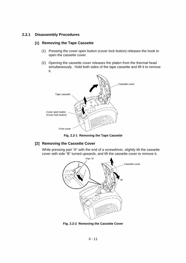
[1] Removing the Tape Cassette
(1) Pressing the cover open button (cover lock button) releases the hook toopen the cassette cover.
(2) Opening the cassette cover releases the platen from the thermal headsimultaneously. Hold both sides of the tape cassette and lift it to removeit.
Fig. 2.2-1 Removing the Tape Cassette
[2] Removing the Cassette Cover
While pressing part “A” with the end of a screwdriver, slightly tilt the cassettecover with side “B” turned upwards, and lift the cassette cover to remove it.
Fig. 2.2-2 Removing the Cassette Cover
Cassette cover
Front cover
Cover open button(Cover lock button)
Tape cassette
Part “A”
“B”
Cassette cover

II - 12
[3] Disassembly of the Cassette Cover Components
(1) Release each of the three hooks of the cassette cover securing thecassette presser with the end of a screwdriver to remove the cassettepresser. Removing the cassette presser removes the cassette spring.
Fig. 2.2-3 Removing the Cassette Presser and Spring
(2) Release the hooks on both sides of the cover lock actuator with the end ofa screwdriver to remove the cover lock actuator. Removing the cover lockactuator removes the cover lock spring.
Fig. 2.2-4 Removing the Cover Lock Actuator and Spring
Cassette presser
Cassette cover
Hooks
Cassette spring
Cover lock actuator
Cassette cover
Cover lock spring

II - 13
[4] Removing the Lower Cover
Turn the machine over, and remove the screw from the lower cover to removethe lower cover.
Fig. 2.2-5 Removing the Lower Cover
Screw
Bottom cover
Lower cover
II - 14
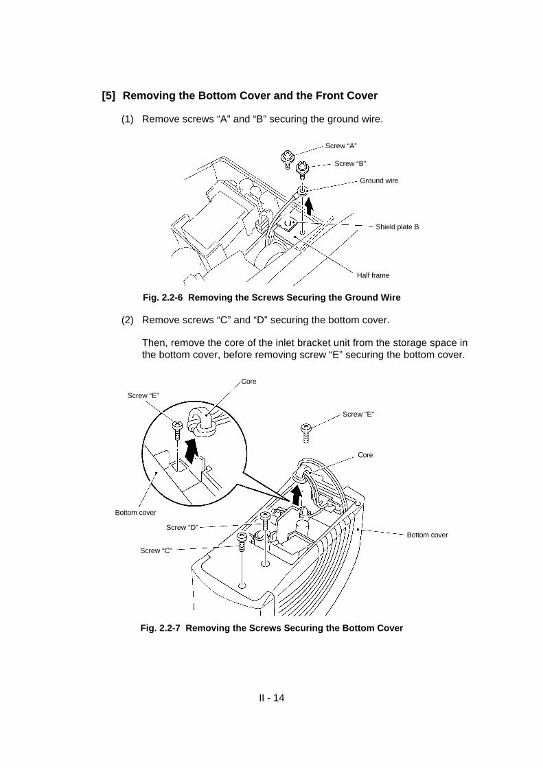
[5] Removing the Bottom Cover and the Front Cover
(1) Remove screws “A” and “B” securing the ground wire.
Fig. 2.2-6 Removing the Screws Securing the Ground Wire
(2) Remove screws “C” and “D” securing the bottom cover.
Then, remove the core of the inlet bracket unit from the storage space inthe bottom cover, before removing screw “E” securing the bottom cover.
Fig. 2.2-7 Removing the Screws Securing the Bottom Cover
Screw “A”
Shield plate B
Half frame
Ground wire
Screw “B”
Core
Bottom cover
Screw “C”
Screw “D”Bottom cover
Core
Screw “E”
Screw “E”

II - 15
(3) While pressing the body cover, lift both sides of the bottom cover toremove it.
(4) Pull out the power supply harness and connector from the main PCB.
Caution: Do not pull the harness; hold the connector to pull it out.
Fig. 2.2-8 Removing the Power Supply Harness and Connector
(5) While pressing the body cover, lift the front cover diagonally to remove it.
Fig. 2.2-9 Removing the Front Cover
Power supply harness
Main PCB
Bottom cover
Front cover
Body cover
Main PCB

II - 16
[6] Removing the Power Supply PCB Assy
(1) Remove the two screws securing the inlet bracket.
(2) Turn the bottom cover over and remove the inlet unit.
Fig. 2.2-10 Removing the Inlet Unit
(3) Remove the two screws securing the power supply PCB assy.
(4) Release the power supply harness from the hook of the bottom cover, andlift the power supply PCB assy to remove it.
(5) Lift shield plate B to remove it.
Fig. 2.2-11 Removing the Power Supply PCB Assy and Shield Plate B
Bottom cover
Two screws
Shield plate B
Power supply PCB assy
Two screws
Inlet unit
Bottom cover

II - 17
(6) Remove the two screws securing the inlet assy to remove the inlet assyfrom the inlet bracket.
Fig. 2.2-12 Removing the Inlet Assy
(7) Remove the inlet assy and power supply harnesses from the power supplyPCB assy.
Fig. 2.2-13 Removing the Inlet Assy and Power Supply Harnesses
Inlet bracket
Two screws
Inlet assy
Power supply harness
Power supply PCB assy
Inlet assy harness

II - 18
[7] Removing the Main PCB Assy and the Mechanical Printing Unit
(1) Unplug the following connectors and cables.
Caution 1: Be sure to unlock the connector before removing the headflexible cable.
Caution 2: Take care not to damage the connectors and cables.
Fig. 2.2-14 Removing the Connectors and Cables
Half cutter sensor connector (P8)
Sensor PCB harness (P3)
Sub PCB harness (P2)
Head flexible cable (P9)
Connector to be unlocked
Tape end sensor connector (P4)
Half cutter motor connector (P6)
Main PCB assy
Full cutter motor connector (P5)
Power supply connector (P1)
Body cover
Tape feed motor connector (P10)
Full cutter sensor connector (P7)

II - 19
(2) Remove the three screws securing the main PCB, disconnect one terminalof the FG harness,and lift the top of the main PCB assy to remove it.
Fig. 2.2-15 Removing the Main PCB Assy
(3) Remove the two screws securing the FG harness and the mechanicalprinting unit to remove them.
Fig. 2.2-16 Removing the Mechanical Printing Unit
FG harness
With cover
Without cover
Mechanical printing unit
Body cover
Main PCB assy
Three screws
Two screws
Body cover
FG harness
With cover
Without cover
Mechanical printing unit

II - 20
[8] Disassembly of the Body Cover
(1) Remove the two screws from the cassette cover bracket, and lift thecassette cover bracket to remove it.
Fig. 2.2-17 Removing the Cassette Cover Bracket
(2) Rotate the cover open cam in direction “A” until it stops and then remove it.
Fig. 2.2-18 Removing the Cover Open Cam
Cassette cover bracket
Body cover
Two screws
Cassette cover bracket
“A”
Cover open cam
II - 21
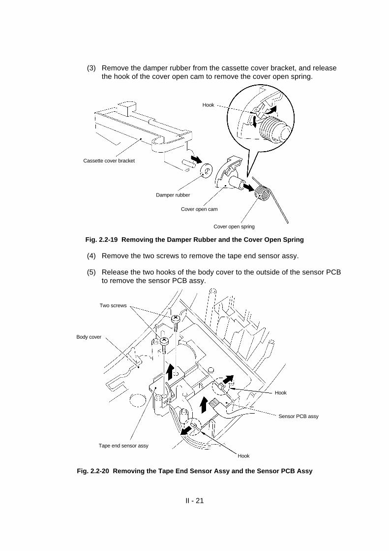
(3) Remove the damper rubber from the cassette cover bracket, and releasethe hook of the cover open cam to remove the cover open spring.
Fig. 2.2-19 Removing the Damper Rubber and the Cover Open Spring
(4) Remove the two screws to remove the tape end sensor assy.
(5) Release the two hooks of the body cover to the outside of the sensor PCBto remove the sensor PCB assy.
Fig. 2.2-20 Removing the Tape End Sensor Assy and the Sensor PCB Assy
Tape end sensor assy
Two screws
Body cover
Sensor PCB assy
Hook
Hook
Cover open spring
Cover open cam
Damper rubber
Cassette cover bracket
Hook

II - 22
(6) Remove the two screws to remove the sub PCB assy.
(7) Press the cut feed button, the power supply actuator, and the powersupply switch button secured on the sub PCB assy from the front of thebody cover to remove them.
Remove the power supply switch button from the power supply actuator.
Fig. 2.2-21 Removing the Sub PCB Assy and the Button
(8) Release the two hooks on the back of the cover lock button to remove thecover lock button from the body cover.
(9) Remove the cover lock spring.
Fig. 2.2-22 Removing the Cover Lock Button and Spring
Two screwsPower supply switch button(ON/OFF key)
Power supply actuator
Sub PCB assy
Cut feed button(FEED/CUT key)
Body cover
Hooks
Body cover
Cover lock button
Cover lock spring
Hooks
II - 23
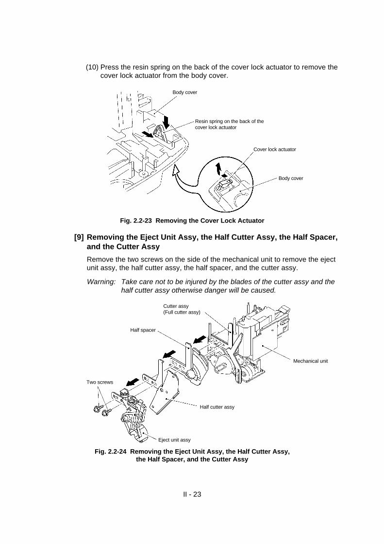
(10) Press the resin spring on the back of the cover lock actuator to remove thecover lock actuator from the body cover.
Fig. 2.2-23 Removing the Cover Lock Actuator
[9] Removing the Eject Unit Assy, the Half Cutter Assy, the Half Spacer,and the Cutter Assy
Remove the two screws on the side of the mechanical unit to remove the ejectunit assy, the half cutter assy, the half spacer, and the cutter assy.
Warning: Take care not to be injured by the blades of the cutter assy and thehalf cutter assy otherwise danger will be caused.
Fig. 2.2-24 Removing the Eject Unit Assy, the Half Cutter Assy,the Half Spacer, and the Cutter Assy
Cutter assy(Full cutter assy)
Half spacer
Two screws
Eject unit assy
Half cutter assy
Mechanical unit
Body cover
Body cover
Cover lock actuator
Resin spring on the back of thecover lock actuator

II - 24
[10]Removing the Half Frame Assy
(1) Remove the half rock gear.
(2) Remove the retaining ring from the cutter helical gear to remove the cutterhelical gear.
Fig. 2.2-25 Removing the Half Rock Gear and the Cutter Helical Gear
(3) Remove the two screws to remove the half cutter sensor assy and the fullcutter sensor assy.
Fig. 2.2-26 Removing the Half Cutter Sensor Assy and the Full Cutter Sensor Assy
Cutter helical gear
Retaining ring
Half rock gear
Half frame assy
Main frame
Full cutter sensor assyScrews
Half cutter sensor assy
Half frame assy

II - 25
(4) Remove the two screws to remove the half cutter motor assy.
(5) Remove the two screws from the full cutter motor assy, and pull the fullcutter motor assy backward to remove it. At this time, take care not todamage the motor worm gear.
Fig. 2.2-27 Removing the Half Cutter Motor Assy and the Full Cutter Motor Assy
(6) Remove the two screws from the half frame assy to remove it.
Fig. 2.2-28 Removing the Half Frame Assy
Half cutter motor assy
Two screws
Half frame assy
Full cutter motor assy
Two screws
Main frame
Half frame assy
Two screws

II - 26
[11]Disassembly of the Mechanical Unit
(1) Remove the two screws from the back of the tape feed motor to removethe tape feed motor assy.
Fig. 2.2-29 Removing the Tape Feed Motor Assy
(2) Remove the two screws and press the back of the head/roller holder unitto remove it. At this time, detach the tape securing the thermal head cableon the frame assy.
Fig. 2.2-30 Removing the Head/Roller Holder Unit
Main frameTape feed motor assy
Two screws
Two screws
Head assy
Securing tapeThermal head cable
Main frame
Head/roller holder unit

II - 27
(3) Pull the release lever spring slightly to remove it.
(4) After removing the retaining ring, remove the roller release rod while tiltingit in direction “A”.
(5) Pull the release cam out of the shaft.
(6) As the release rod roller is secured in place by the elasticity of the resin ofthe roller release rod, press the shaft of the release rod roller to remove itfrom the roller release rod.
Fig. 2.2-31 Removing the Roller Release Rod
Roller release rod
“A”
Main frame Roller release rod
Release lever spring
Main frame
Release lever spring
Release rod rollerRetaining ring
Release cam
II - 28
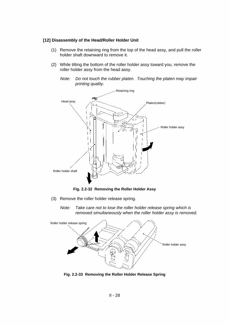
[12] Disassembly of the Head/Roller Holder Unit
(1) Remove the retaining ring from the top of the head assy, and pull the rollerholder shaft downward to remove it.
(2) While tilting the bottom of the roller holder assy toward you, remove theroller holder assy from the head assy.
Note: Do not touch the rubber platen. Touching the platen may impairprinting quality.
Fig. 2.2-32 Removing the Roller Holder Assy
(3) Remove the roller holder release spring.
Note: Take care not to lose the roller holder release spring which isremoved simultaneously when the roller holder assy is removed.
Fig. 2.2-33 Removing the Roller Holder Release Spring
Retaining ring
Head assy
Roller holder shaft
Roller holder assy
Platen(rubber)
Roller holder release spring
Roller holder assy

II - 29
2.2.2 Reassembly Procedures
[1] Reassembly of the Head/Roller Holder Unit
(1) Apply the specified grease (1 mm3) on each of the top and bottom of theplaten shaft of the roller holder assy. (Specified grease: Silicone greaseG501)
Fig. 2.2-34 Applying the Grease on the Platen Shaft
(2) Set the roller holder release spring at the bottom of the shaft of the rollerholder assy. With one of the hooks of the roller holder release springinserted into the groove in the roller holder, insert the platen shaft at thetop of the roller holder assy, into the slit at the top of the head assy, whiletilting the roller holder assy.
Then, insert the shaft at the bottom into the slit at the bottom of the headassy to set the roller holder assy.
At this time, check that the release spring is hooked on the correct portionof the head assy.
(3) After inserting the roller holder shaft from the bottom of the head assy, setthe retaining ring at the top of the shaft.
At this state, check that the roller holder rotates smoothly by pressing theback of the roller holder assy.
Fig. 2.2-35 Reassembly of the Roller Holder Assy
Top of the platen shaft
Bottom of the platen shaft
Roller holder assy
Retaining ring
Head assy
Roller holder shaft
Roller holder release spring
Roller holder assy
II - 30
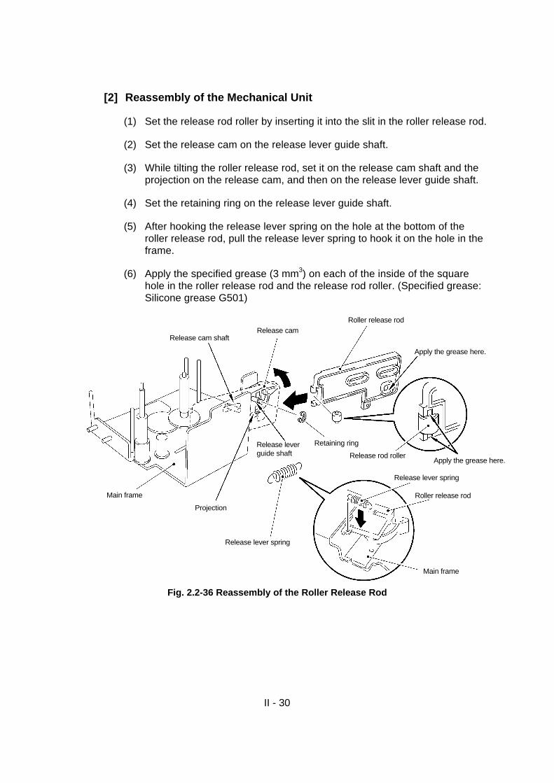
[2] Reassembly of the Mechanical Unit
(1) Set the release rod roller by inserting it into the slit in the roller release rod.
(2) Set the release cam on the release lever guide shaft.
(3) While tilting the roller release rod, set it on the release cam shaft and theprojection on the release cam, and then on the release lever guide shaft.
(4) Set the retaining ring on the release lever guide shaft.
(5) After hooking the release lever spring on the hole at the bottom of theroller release rod, pull the release lever spring to hook it on the hole in theframe.
(6) Apply the specified grease (3 mm3) on each of the inside of the squarehole in the roller release rod and the release rod roller. (Specified grease:Silicone grease G501)
Fig. 2.2-36 Reassembly of the Roller Release Rod
Roller release rodRelease cam
Apply the grease here.Release rod roller
Release cam shaft
Release lever spring
Roller release rod
Main frame
Release lever spring
Main frame
Projection
Release leverguide shaft
Retaining ring
Apply the grease here.

II - 31
(7) After passing the harness through the oblong hole in the frame and settingthe head/roller holder unit on the boss and the hole in the frame, tightenthe two screws.
(8) Check that the roller holder rotates smoothly by moving the release camvertically.
Fig. 2.2-37 Reassembly of the Head/Roller Holder Unit
(9) Set the tape feed motor assy on the frame, and tighten the screws fromthe back of the frame.
Note: Backlash on the motor gear should be 0.05 to 0.3 mm.
Fig. 2.2-38 Reassembly of the Tape Feed Motor Assy
Two screws
Oblong hole in the main frame
Head assy
Main frame
Boss on the main frame
Head/roller holder unit
Main frame
Tape feed motor assy
Two screws

II - 32
[3] Reassembly of the Half Frame Assy
(1) With the holes in the frame set on the bosses on the half frame assy,tighten the two screws from the half frame side.
Fig. 2.2-39 Reassembly of the Half Frame Assy
(2) After applying the specified grease (2 mm3) on the end of the motor wormgear, insert the full cutter motor assy into the square hole in the half frameassy from the back then insert the end of the motor worm gear into thesmall hole in the half frame. After that tighten the two screws with the endof the motor worm gear pressed downward. (Specified grease: Siliconegrease G501)
(3) Insert the half cutter motor assy from the back of the half frame assy, andtighten the two screws. Then, apply the specified grease (3 mm3) on thegear of the half cutter motor assy. (Specified grease: Silicone greaseG501)Backlash on the motor gear should be 0.05 to 0.3 mm.
Fig. 2.2-40 Reassembly of the Half Cutter Motor Assy and the Full Cutter Motor Assy
Boss on the half frame
Boss on the half frame
Half frame assy
Two screws
Main frame
Half cutter motor assy
Apply the grease here.
Two screws
Half frame assy
Full cutter motor assy
Two screws
Apply the grease here.

II - 33
(4) After setting the half cutter sensor assy and the full cutter sensor assy inplace, tighten the screw for each of them.
Check that the projections on the sensors are inserted into the holes in thehalf frame.
Note: Observe the colors of their harnesses (half cutter sensor harness:black, full cutter sensor harness: blue).
Fig. 2.2-41 Reassembly of the Half Cutter Sensor Assy and the Full Cutter Sensor Assy
(5) Mount the cutter helical gear onto the shaft and check to be sure that thebacklash between the helical gear and the cutter worm gear is 0 to 0.1mm. If the backlash is greater than this range, remove the two screws ofthe full cutter motor and adjust the backlash correctly. After obtaining thecorrect amount of backlash, set the retaining ring on the shaft.
(6) Set the half rock gear with its groove tilted at an approximately 45° angle.Then, apply the specified grease (3 mm3) on the inside of the groove.(Specified grease: Silicone grease G501)
Fig. 2.2-42 Reassembly of the Cutter Helical Gear and the Half Rock Gear
Half cutter sensor assy
Mechanical unit
Half frame assy
Screw
Projection
Projection
Screw
Full cutter sensor assy
45° Cutter helical gear
Retaining ringApply the grease here.
Half rock gear
Half frame assy

II - 34
[4] Reassembly of the Cutter Assy, the Half Spacer, the Half CutterAssy, and the Eject Unit Assy
(1) Apply the specified grease (3 mm3) on each slot of the cams in the cutterassy and the eject unit assy, where the cutter rock pin slides up and down.(Specified grease: Silicone grease G501)
(2) After inserting the cutter rock pin into the groove in the movable blade ofthe cutter assy, insert the two locating shafts of the frame assy into theround and oblong holes.
Warning : Take care not to be injured by the blades of the cutter assyand the half cutter assy otherwise danger will be caused.
(3) Insert the two locating shafts of the frame assy into the round and oblongholes in the half spacer.
(4) After inserting the half rock pin of the half cutter assy into the groove in thehalf rock gear, insert the two locating shafts of the frame assy into theround and oblong holes.
(5) After setting the eject cam of the eject unit assy on the cutter rock pin,insert the two locating shafts of the frame assy into the round and oblongholes.
(6) While pressing the vicinity of the screws to be tightened on each of theabove four units, tighten the two screws.
Fig. 2.2-43 Reassembly of the Cutter Assy, the Half Spacer,the Half Cutter Assy, and the Eject Unit Assy
Cutter assy(Full cutter assy)
Locating shafts
Half spacer
Half cutter assy
Eject unit assy
Two screws
Apply the grease here.
Cutter rock pin
Apply the grease here.
Cutter rock pin
Mechanical unit

II-35
[5] Reassembly of the Body Cover
(1) Set the cover lock actuator on the hole in the body cover diagonally fromthe top. Check that the resin spring of the cover lock actuator is securelyset in the body cover.
Fig. 2.2-44 Reassembly of the Cover Lock Actuator
(2) Press-fit the cover lock spring on the projection on the back of the coverlock button while slightly rotating the cover lock spring.
(3) Align the cover lock spring set in the cover lock button on the projection ofthe body cover for the cover lock spring to set the cover lock button in thebody cover.
Check that the cover lock actuator slides smoothly by pressing the coverlock button.
Fig. 2.2-45 Reassembly of the Cover Lock Spring and Button
Cover lock actuator
Body cover
Resin spring of the cover lock actuator
Body cover
Cover lock button
Cover lock spring
Body cover
Hooks

II-36
(4) Turn the body cover over, and set the cut feed button on the projectionand hole “B” in the body cover.
(5) Insert the projection on the power supply switch button into the guide ofthe power supply actuator. With the three projections set, set this buttonon the projection and hole “A” in the body cover.
(6) Set the hole and the slit of the sub PCB assy on the projections of thebody cover, and tighten the two screws. At this time, check if the solder ofthe harness has peeled off.
Fig. 2.2-46 Reassembly of the Button and the Sub PCB Assy
(7) Set the sensor PCB assy on the two hooks of the body cover and pressthe sensor PCB until these hooks click. (There is no screw to betightened.) Check if the solder of the harness has peeled off.
(8) Insert the tape end sensor assy into the square hole in the body cover,and tighten the two screws.
Insert the tape end sensor harness into the groove in the body cover.
Fig. 2.2-47 Reassembly of the Sensor PCB Assy and the Tape End Sensor Assy
Two screws
Body cover
Tape end sensor assy
Groove in the body cover
Hook
Sensor PCB assy
Hook
Two screws
Power supply switch button(ON/OFF key)
Power supply actuator
Cut feed button (FEED/CUT key)
Hole “A”Hole “B”
Projection
Projection
Body cover
Projections
Sub PCB assy
Hole
Slit

II-37
(9) Set the cover open spring on the cover open cam. While rotating thecover open spring, set the shorter of its hooks on the hook of the coveropen cam.
(10) Apply the specified grease (3 mm3) on the cassette cover bracket and setthe damper rubber on the shaft on the side of the cassette cover bracket.(Specified grease: Silicone grease G501)
(11) Apply the specified grease (1 mm3) on the damper rubber, then set theassy of the cover open cam and the cover open spring on the shaft of thecassette cover bracket in the manner the damper rubber is sandwichedbetween the assy and the bracket. (Specified grease: Silicone greaseG501)
Fig. 2.2-48 Reassembly of the Cover Open Cam
(12) Align the two locating projections on the body cover with the holes in thecassette cover bracket to set the cassette cover bracket on the bodycover. At this time, check that the longer of the hooks of the cover openspring is set on the projection on the body cover. Subsequently, tightenthe two screws.
Fig. 2.2-49 Reassembly of the Cassette Cover Bracket
Cassette cover bracket
Cover open spring
Body cover
Locating projections
Cassette cover bracket
Body cover
Two screws
Apply the grease on the back
Cassette cover bracket
Damper rubber
Cover open cam
Cover open spring
Apply thegrease here
Hook

II-38
[6] Reassembly of the Mechanical Printing Unit and the Main PCB assy
(1) Set the mechanical printing unit vertically on the three locating projectionson the body cover. At this time, take care not to sandwich the harnessesand connectors inbetween.
Tighten the FG harness together with the mechanical printing unit usingone screw,and tighten the other screw,too.
Note: Tighten the terminal of the FG harness having no cover at thecrimp terminal.
Fig. 2.2-50 Reassembly of the Mechanical Printing Unit
Two screws
FG harness
With cover
Without cover
Mechanical printing unit
Body cover

II-39
(2) Keep the ends of the harnesses, and the connectors out of the main PCBassy. While tilting the main PCB assy, plug the serial I/F connector andUSB I/F connector into the corresponding square holes at the bottom ofthe body cover, and then set the main PCB on the two projections on thebody cover, with sandwiched inbetween. Subsequently, tighten the threescrews together with the FG harness.
Note 1: Be sure to tighten the crimp terminal of the FG harness equipped with a cover.
Note 2: If the main PCB assy has been replaced, refer to section 3.2.1 logic and related matter and section 3.4 description of model name and serial number writing software.
Fig. 2.2-51 Reassembly of the Main PCB Assy
(3) Attach the head flexible cable on the back of the main frame with a tape.
Fig. 2.2-52 Attaching the Head Flexible Cable with Tape
With cover
Without cover
Square holes
FG harness
Mechanical printing unit
Body cover
Main PCB assy
USB I/F connector
Serial I/F connector
Three screws
Main frame
Securing tape
Head flexible cable

II-40
(4) Set the following connectors and cables.
Note: Unlock the connector before inserting the head flexible cable, andthen lock the connector after inserting the cable. (Insert thecorrect end of the cable.)
Note: If the thermal head is replaced, change the soldering point on themain PCB meeting the resistance value of the new thermal head.After the soldering point has been changed,check if solder isremoved completely from the soldering point,using a multimeter orthe like.
Thermal Head Resistance Values and Soldering Points
Thermal head resistance value L A B C D E F S
Soldering point L A B C D E F S
Fig. 2.2-53 Setting the Connectors and Cables
Fig. 2.2-54 Changing the Soldering Point
Half cutter sensor connector(P8) Full cutter sensor connector(P7)
Sensor PCB harness(P3)
Sub PCB harness(P2)
Head flexible cable(P9)Connector to be locked
Tape end sensor connector(P4)
Half cutter motor connector(P6)
Main PCB assy
Body cover
Full cutter motorconnector(P5)
Power supply connector(P1)
Tape feed motor connector(P10)
Soldering point
7 digits
Resistance value
Head flexible cable
Main PCB assy

II-41
[7] Reassembly of the Power Supply PCB Assy
(1) After orienting the inlet assy correctly in the inlet bracket, tighten the twoscrews.
Note: Always mount the inlet assy in the inlet bracket in the directionshown in the illustration below.
Fig. 2.2-55 Reassembly of the Inlet Assy
(2) Turn the bottom cover over, and set the oblong hole in shield plate B onthe projection on the bottom cover to set shield plate B on the bottomcover.
(3) After plugging the inlet assy and power supply harnesses into theconnectors on the power supply PCB, set the power supply PCB assy onthe bottom cover, with shield plate B sandwiched inbetween. Then,tighten the two screws.
Fig. 2.2-56 Reassembly of the Shield Plate B and the Power Supply PCB Assy
Inlet bracket
Two screws
Inlet assy
Inlet harness
Bottom cover
Shield plate B
Power supply PCB assy
Power supply harness
Two screws

II-42
(4) Set the inlet bracket on the right and left projections on the bottom cover,and tighten the two screws.
Fig. 2.2-57 Reassembly of the Inlet Unit
(5) Pass the power supply harness through the hole in the bottom cover, andsecure it on the hook of the bottom cover.
Fig. 2.2-58 Securing the Power Supply Harness
Two screws
Inlet unit
Bottom cover
Power supply harness
Bottom cover

II-43
(6) Store the two large and small cores in the storage space in the bottomcover, and insert the two harnesses (blue and brown) into the slits in theinlet bracket.
Fig. 2.2-59 Running the Inlet Unit Harnesses
Body cover
Core

II-44
[8] Reassembly of the Covers
(1) Turn the body cover. After setting the front cover on the two ribs of thebody cover, set the front cover on the hook.
Fig. 2.2-60 Reassembly of the Front Cover
(2) Insert the power supply harness into the connector on the main PCB.
Fig. 2.2-61 Connecting the Power Supply Harness and Connector
HookRib Rib
Front cover Body cover
Mechanical printing unit
Power supply harness
Main PCB
Bottom cover

II-45
(3) Place the bottom cover on the body cover and the front cover toreassemble them.
Press the bottom cover against the body cover vertically and horizontallyuntil the four hooks inside the body cover click.
(4) Tighten screws “C” and “D” securing the bottom cover.
Pull out the (large) core from the storage space, and tighten screw “E”.
Fig. 2.2-62 Reassembly of the Body Cover and the Bottom Cover
(5) Tighten screws “A” and “B” to secure shield plate B and the ground wire onthe half frame. And insert the core into the cover.
Fig. 2.2-63 Tightening the Screw to Secure the Ground Wire
Screw “A”
Core
Half frame
Shield plate B
Ground wire
Screw “B”
Core
Body cover
Screw “E”
Screw “D”
Screw “C”
Body cover
Core
Screw “E”

II-46
(6) Set the lower cover on the bottom cover, and tighten the screw.
Fig. 2.2-64 Reassembly of the Lower cover
Screw
Lower cover
Bottom cover

II-47
[9] Reassembly of the Cassette Cover Components
(1) Set the cover lock spring on the projection on the cover lock actuator, andinsert it until it locks into the guide of the cassette cover. After inserting it,check that the cover lock actuator operates smoothly by pressing its end.
Fig. 2.2-65 Reassembly of the Cover Lock Actuator
(2) Press-fit the cassette spring on the projection on the back of the cassettepresser while slightly rotating the cassette spring.
(3) Set the cassette presser. At this time, check that the cassette spring is seton the projection on the cassette cover by viewing it from the side.
After setting it, check that the three hooks are securely locked and that thecassette presser operates smoothly.
Fig. 2.2-66 Reassembly of the Cassette Presser
Cassette cover
Cover lock spring
Cover lock actuator
Cassette presser
Cassette spring
Cassette cover
Cassette presser
Cassette spring

II-48
[10] Reassembly of the Cassette Cover
(1) While pressing the two projections on the cassette cover bracket to theoutside, insert the two projections on the cassette cover bracket into theholes on both sides of the cassette cover.
Check that the cover open cam is engaged with the right projection on thecassette cover.
(2) Check that the cassette cover opens and closes properly.
Fig. 2.2-67 Reassembly of the Cassette Cover
[11] Reassembly of the Tape Cassette
Press the cover open button (cover lock button) to open the cassette cover.
Set the tape cassette from the top, and then close the cassette cover.
Fig. 2.2-68 Reassembly of the Tape Cassette
Cassette cover
Cassette cover Cover open cam
Body cover
Projections on the cassettecover bracket
Cover open button(Cover lock button)
Tape cassette
Cassette cover

II-49
[12] Test Printing and Operation Check
(1) Plug the AC cord into the machine.
(2) With the ON/OFF ( ) key held pressed, press the FEED/CUT ( ) keytwice to perform test printing.
(3) During test printing, check if the tape is fed correctly for printing, and if it iscut correctly.
If any problem is found, refer to CHAPTER IV TROUBLESHOOTING.
(4) Check that opening the cassette cover releases the roller holder assy fromthe thermal head, and that closing the cassette cover crimps the rollerholder assy on the thermal head.
(5) Check that the FEED/CUT ( ) key operates correctly.
(6) Check that the ON/OFF ( ) key operates correctly.
• LED (ON/OFF key) Display
State of the LED Display
Lights up in green. Data reception standby mode.
Blinks in green. Data has been received.
Lights up in orange. No cassette is present in the data reception standby mode.
The cover is open while data is being received (before printing).
Blinks in orange. The cover is open in the data reception standby mode.
Blinks in red. No cassette is present during printing.
Tape end.
Replace the cassette.
The cover is open during printing.
Communications error.
Buffer error.
Lights up in red. Cutter jam (before and during printing, and when power is turned on).
EEPROM error.
RAM error.

II-50
[13] Error Code
A list of error codes for the baud rate change wizard of PT-9200DX (related tocommunications and connection) is shown below.
The language monitor displays the error number only.
ErrorNumber
Description Note
1 Failure to open COMport
The port is occupied by another application or aserial communication device. Finish the applicationor uninstall it, or delete the driver of the serialcommunication device.
2 Get Comm failure Function failure at API level.
(API: Application interface)
3 Build Comm failure Function failure at API level.
(API: Application interface)
4 Set Comm Timeoutfailure
Function failure at API level.
(API: Application interface)
5 No applicable baudrate
This error is caused by complex factors actually.
The probable cause includes cable breakage,conversion connector wiring, machine breakage,and occupancy, concealment or internalrenumbering of port by another serialcommunication device.
6 Failure to write baudrate changecommand
Check if the power is shut down during operation orthe cable is disconnected or other causes related tothe power supply.
7 Failure to read baudrate changecommand
Check if the power is shut down during operation orthe cable is disconnected or other causes related tothe power supply.
8 Build Comm failure Function failure at API level.
(API: Application interface)
9 Failure to write statusrequest duringconfirmation
Check if the power is shut down during operation orthe cable is disconnected or other causes related tothe power supply.
10 Failure to read statusrequest duringconfirmation
Check if the power is shut down during operation orthe cable is disconnected or other causes related tothe power supply.
50 Baud rate notsupported by PC
The designated baud rate is not supported by thePC. Set the baud rate at 9600.
99 Shutdown orsomething related toCOM port
Check the power supply. This error is sometimescaused by complex factors. The probable causeincludes cable breakage, conversion connectorwiring, machine breakage, and occupancy,concealment or internal renumbering of port byanother serial communication device.
II-51
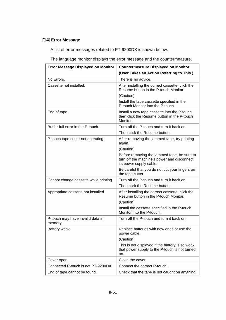
[14] Error Message
A list of error messages related to PT-9200DX is shown below.
The language monitor displays the error message and the countermeasure.
Error Message Displayed on Monitor Countermeasure Displayed on Monitor
(User Takes an Action Referring to This.)
No Errors. There is no advice.
Cassette not installed. After installing the correct cassette, click theResume button in the P-touch Monitor.
(Caution)
Install the tape cassette specified in theP-touch Monitor into the P-touch.
End of tape. Install a new tape cassette into the P-touch,then click the Resume button in the P-touchMonitor.
Buffer full error in the P-touch. Turn off the P-touch and turn it back on.
Then click the Resume button.
P-touch tape cutter not operating. After removing the jammed tape, try printingagain.
(Caution)
Before removing the jammed tape, be sure toturn off the machine's power and disconnectits power supply cable.
Be careful that you do not cut your fingers onthe tape cutter.
Cannot change cassette while printing. Turn off the P-touch and turn it back on.
Then click the Resume button.
Appropriate cassette not installed. After installing the correct cassette, click theResume button in the P-touch Monitor.
(Caution)
Install the cassette specified in the P-touchMonitor into the P-touch.
P-touch may have invalid data inmemory.
Turn off the P-touch and turn it back on.
Battery weak. Replace batteries with new ones or use thepower cable.
(Caution)
This is not displayed if the battery is so weakthat power supply to the P-touch is not turnedon.
Cover open. Close the cover.
Connected P-touch is not PT-9200DX. Connect the correct P-touch.
End of tape cannot be found. Check that the tape is not caught on anything.

II-52
Error Message Displayed on Monitor Countermeasure Displayed on Monitor
(User Takes an Action Referring to This.)
Wrong AC adapter connected. Use the AC adapter designed exclusively forthis unit.
Communication error between PC andP-touch.
Check for the following.
Communication error in the P-touch. Start up the Change Baud Rate Wizard.
However, the current job should be deletedbefore starting it up.
Transmission settings incorrect. A communication error occurs within theP-touch due to an over-run error, acommunication buffer full error, etc.
Not enough memory to print document. Try again after the other application isfinished.
Not enough disk space to spooldocument.
Make sure that there is enough free space onthe disk.
Invalid port was specified. Select a valid COM port using the ControlPanel and Resume.
Port being used for another application. Try again after the other application isfinished.
(Caution)
If this error occurs, check for the following.
- Is a mail application which uses the sameport as the P-touch not running?
- Is transmission software that uses the sameport as the P-touch not being usedimmediately before?
- Is the same port selected by more than oneP-touch units?
Error of unknown cause occurred. Unexpected error occurred. Make a copy ofthe Fault Report sheet, fill in the necessaryinformation, and then fax it to your servicerepresentative.

CHAPTER III
ELECTRONICS

CONTENTS
CHAPTER III ELECTRONICS
3.1 CONFIGURATION OF THE ELECTRONIC PART ...................................................................... III-1
3.1.1 Main PCB...................................................................................................................... III-1
3.1.2 Power Supply PCB ........................................................................................................ III-1
3.1.3 Cassette Sensor PCB (Sensor PCB).............................................................................. III-2
3.1.4 Tape End Sensor PCB .................................................................................................. III-2
3.1.5 Switch and LED PCB (Sub PCB) ................................................................................... III-2
3.1.6 Full Cutter Sensor ......................................................................................................... III-2
3.1.7 Half Cutter Sensor......................................................................................................... III-2
3.1.8 Full Cutter Motor ........................................................................................................... III-2
3.1.9 Half Cutter Motor........................................................................................................... III-2
3.1.10 Tape Feed Motor........................................................................................................... III-2
3.1.11 Thermal Head ............................................................................................................... III-2
3.2 MAIN PCB .................................................................................................................................. III-3
3.2.1 Logic Components......................................................................................................... III-4
[1] CPU (M30622M8) ................................................................................................... III-4
[2] RAM (SRAM) .......................................................................................................... III-4
[3] ROM (EEPROM)..................................................................................................... III-4
3.2.2 Solder Points................................................................................................................. III-5
3.2.3 Logic and VH Power, and Related Circuits..................................................................... III-5
3.2.4 Stepping Motor (Tape Feed Motor) Drive Circuit............................................................ III-6
3.2.5 DC Motor (Cutter Motor) Drive Circuit............................................................................ III-8
[1] Full Cutter Motor Drive Circuit and Full Cutter Sensor Circuit .................................. III-9
[2] Half Cutter Motor Drive Circuit and Half Cutter Sensor Circuit................................. III-9
[3] Process of Full or Half Cutter Errors...................................................................... III-10
3.2.6 Cassette Detection Sensor Circuit ............................................................................... III-10
3.2.7 Thermal Head Control Circuit ...................................................................................... III-11
[1] Basic Energizing Time .......................................................................................... III-12
[2] Log Control ........................................................................................................... III-12
[3] 4-Dot Control......................................................................................................... III-12
[4] Control by Ribbon Type......................................................................................... III-12
[5] Control by the Resistance Level of the Thermal Head........................................... III-12
[6] Temperature Control ............................................................................................. III-12
3.2.8 Head Temperature Detection Circuit............................................................................ III-13
3.2.9 Oscillation Circuit ........................................................................................................ III-13
3.2.10 Interface Circuit ........................................................................................................... III-14
[1] Serial Interface Circuit........................................................................................... III-14
[2] USB Interface Circuit ............................................................................................ III-15
3.2.11 Tape End Sensor Circuit.............................................................................................. III-16
3.2.12 Switch and LED Circuit ................................................................................................ III-16
3.2.13 Cover Open Sensor Circuit.......................................................................................... III-17

3.3 POWER SUPPLY PCB ............................................................................................................. III-17
3.4 Description of Model Name and Serial Number Writing Software PT-9200DX........................... III-18
3.4.1 Operation Procedure ................................................................................................... III-18
3.4.2 Troubleshooting in Case of Error ................................................................................. III-20

III - 1
3.1 CONFIGURATION OF THE ELECTRONIC PARTFig. 3.1-1 shows the configuration of the electronic part.
The electronic part consists of the following components.
Fig. 3.1-1 Configuration of the Electronic Part
3.1.1 Main PCB
The main PCB controls all electronic operations.
This PCB consists of the CPU, the RAM, the EEPROM, the Serial I/F driver,USBchip, and the motor driver.
3.1.2 Power Supply PCB
There are two types of power supply PCB (100V-120V system and 220-240Vsystem). This PCB, equipped with a switching regulator, stabilizes commerciallyavailable power (AC voltage) to generate DC voltage. The following two voltagesare output.
VH: 24V DC±0.3V
Vcc: 5V DC±0.25V

III - 2
3.1.3 Cassette Sensor PCB (Sensor PCB)
The cassette sensor PCB (sensor PCB) is equipped with the sensor which detectsthe cassette tape width and ink ribbon type, and the sensor (mechanical switch)which detects the open cassette cover.
3.1.4 Tape End Sensor PCB
The tape end sensor uses a photo-interrupter to detect the tape end (zebra) pattern.
3.1.5 Switch and LED PCB (Sub PCB)
The switch and LED PCB (sub PCB) is equipped with the ON/OFF and FEED/CUTswitches, and the LED (green/red).
3.1.6 Full Cutter Sensor
The full cutter sensor is a sensor (mechanical switch) which detects the position ofthe full cutter.
3.1.7 Half Cutter Sensor
The half cutter sensor is a sensor (mechanical switch) which detects the position ofthe half cutter.
3.1.8 Full Cutter Motor
The full cutter motor is the drive to cut the tape. This DC motor runs at a drivevoltage of VH (24V).
3.1.9 Half Cutter Motor
The half cutter motor is the drive for the half cutting of laminated tapes. This DCmotor runs at a drive voltage of VH (24V).
3.1.10 Tape Feed Motor
The tape feed motor is the drive to feed both the ribbon and the tape. This Ø25stepping motor runs at a drive voltage of VH (24V).
3.1.11 Thermal Head
The thermal head has 384 dots×1 dot (360 dpi), thin-film configuration andincorporates a drive circuit. The drive voltage is 24V.

III - 3
3.2 MAIN PCBFig. 3.2-1 shows the main PCB block diagram.
The main PCB consists of the following components.
(1) CPU (including the ROM and the RAM)
(2) SRAM (128 Kbytes)
(3) EEPROM (1 Kbits)
(4) Power supply, head power supply, FEED key, and LED ON/OFF circuits
(5) Full cutter motor drive circuit, half cutter motor drive circuit, and tape feedmotor drive circuit
(6) Cassette sensor circuit, cover open sensor circuit, automatic full and half cuttersensor circuit, and tape end sensor circuit
(7) Head level detection circuit
(8) Head temperature detection circuit
(9) Reset circuit
(10) RS-232C serial interface circuit
(11) USB interface circuit
Fig. 3.2-1 Main PCB Block Diagram

III - 4
3.2.1 Logic Components
[1] CPU (M30622M8)
The CPU (#1) is a 16-bit microprocessor manufactured by Mitsubishi ElectricCorp., which controls and manages the entire system.
This CPU has a 64-Kbyte internal ROM which stores all programs. Theinternal RAM has 4 Kbytes.
[2] RAM (SRAM)
A 128-Kbyte SRAM (#5) is used as a data buffer.
[3] ROM (EEPROM)
A 1-Kbit EEPROM (#9) is used, into which baud rate,vendor ID code,product IDcode and mechanical information is written to be stored.
After the main PCB assy has been replaced ,the serial number shown on themain body and model name (PT-9200DX) must be stored in the EEPROM onthe main PCB. To do this, Fig.3.2.-2 shows connect the PC with PT-9200DXvia a serial I/F cable, and use special software supplied separately. For details,refer to section 3.4 description of model name and serial number writingsoftware.
Fig. 3.2-2 Model Name and Serial Number Writing
Serial I/F cablePT-9200DX
PC

III - 5
3.2.2 Solder Points
Fig. 3.2-3 shows the solder point circuit.
One of solder points L-S is soldered according to the resistance level of the thermalhead.
After the power is turned on, AN0 and AN3 are read to judge the soldering point incombination with the voltage level.
After the soldering point has been changed, check if solder is completely removedfrom the soldering point, using a multimeter or the like.
Fig. 3.2-3 Solder Point Circuit
3.2.3 Logic and VH Power, and Related Circuits
Power from a commercially available wall outlet is Vcc (+5V±0.25V) which issupplied to the main PCB, and then to all logic components.
When Vcc is supplied, the reset IC (Q5) switches the reset signal level to high tostart the CPU.
When the CPU starts after the power is supplied, ports are initialized, and the CPUenters the sleep state (the power is turned off).
With the power off, pressing the [ON/OFF] key causes the interruption of NMI tostart the CPU, turning on the power.
With the power on, pressing the [ON/OFF] key places the CPU in the sleep state(the power is turned off).
With the machine in operation, P81 is switched to high to turn on Q9 (FET),supplying VH to the thermal head, the full cutter motor, the half cutter motor, andthe tape feed motor.

III - 6
3.2.4 Stepping Motor (Tape Feed Motor) Drive Circuit
Fig. 3.2-4 shows the stepping motor drive circuit.
The Ø25 stepping motor is used to feed the ribbon and the tape. The steppingmotor feeds the tape 1/720 in. for one pulse (one dot for two pulses).
Drive pulses are transmitted from P104-P107 of the CPU (#1) to Q1-Q4 to drive themotor with a unipolar 2-2 phase excitation (AB→DA→CD→BC forward feed).
(1) Printing at fixed speed
The rate of fixed speed printing, at which printing is performed while the tape isfed at a fixed speed, is 571 pps (1.75 msec/pulse).
The through-up pulses (including pre-excitation) and through-down pulses(including post-excitation) are 56 and 5 pulses, respectively.
(2) Halfway stop of printing
If printing is stopped halfway, the circuit continuously drives the motor (overrunfor 198 pulses) after the stop, then shuts off the power.
(3) Printing interruption (margin cutting drive, half cutting drive, and buffer fulldrive)
a) At the interruption of printing, the motor overruns (five through-downpulses) before it stops.
b) If cutter operation is necessary, full or half cutting is performed.
c) The motor rotates counterclockwise for 70 pulses.
d) The motor rotates clockwise to resume printing with 3 dots printed again.
Fig. 3.2-4 Stepping Motor Drive Circuit

III - 7
(4) Printing at low speed
If the head temperature is 41°C or higher during printing on laminated or non-laminated tapes, low speed printing is performed to ensure printing quality.
The through-up pulses (including pre-excitation) and the through-down pulses(including post-excitation) are 56 and 5 pulses, respectively.
The rate of low speed printing is 426 pps (2.35 msec/pulse).

III - 8
3.2.5 DC Motor (Cutter Motor) Drive Circuit
Figs. 3.2-5 and 3.2-6 show the DC motor drive circuit and the cutter sensor circuit,respectively.
The DC motor performs the full or half cutting of the tape. With full cutting, drivepulses are transmitted from DCR1 and DCF1 of the CPU (#1) to BA6919FP (#7) todrive the motor. With half cutting, drive pulses are transmitted from DCR2 andDCF2 of the CPU (#1) to BA6919FP (#8) to drive the motor.
Table 3.2-1 shows the logic of DCR1, DCF1, DCR2, and DCF2.
Fig. 3.2-5 DC Motor Drive Circuit
Fig. 3.2-6 Cutter Sensor Circuit
State DCF1 DCR1 DCF2 DCR2
OFF 0 0 0 0
Clockwise 1 0 1 0
Counterclockwise 0 1 0 1
Brake 1 1 1 1
Table 3.2-1 Logic of the DC Motor Control

III - 9
[1] Full Cutter Motor Drive Circuit and Full Cutter Sensor Circuit
The drive sequence of the full cutter motor is shown below.
The cutter stays at the home position in the normal state. (The full cuttersensor input level is low.)
A tape cutting drive command rotates the DC motor clockwise to cut the tape.At this time, the sensor input level switches from low to high. When this inputlevel switches to low again, it indicates that the cutter has returned to the homeposition after cutting the tape.
When the low level of sensor input is detected, the DC motor brake is applied.When the sensor input level switches to high again during braking, whichindicates that the cutter has passed by the home position, the DC motorrotates counterclockwise. When the sensor input level switches to low again,the motor brake is applied to monitor the sensor input level.
When the sensor input level switches to high, the DC motor rotates clockwise.When it switches to low, the motor brake is applied.
If the sensor input level is low for 100 msec with the brake applied when theabove operations are repeated, the cutter is judged as returned to the homeposition, completing the operations.
If an abnormal end shifts the cutter from the home position, the DC motorrotates counterclockwise before printing to return the cutter to the homeposition (initialization).
If the cutter remains at the home position 300 msec or does not return to thehome position 1000 msec after the DC motor starts rotating clockwise, it isprocessed as an error.
The DC motor does not operate with the cover open, which is detected by thecover open sensor.
[2] Half Cutter Motor Drive Circuit and Half Cutter Sensor Circuit
The cutter stays at the home position in the normal state. (The half cuttersensor input level is low.)
A tape half cutting drive command rotates the DC motor clockwise (for 800msec) for the half cutting of the tape. At this time, the sensor input levelswitches from low to high. Then the DC motor rotates counterclockwise.When the sensor input level switches to low again, the motor brake is applied.
If the sensor input level is low for 100 msec with the brake applied, the cutter isjudged as returned to the home position, completing the operations.
If the cutter remains at the home position with the DC motor rotating clockwiseor does not return to the home position 800 msec after the DC motor startsrotating counterclockwise, it is processed as an error.
The DC motor does not operate with the cover open, which is detected by thecover open sensor.

III - 10
[3] Process of Full or Half Cutter Errors
An error causes LED 1 (red) to light up to disable all operations.
Turning off the ON/OFF switch turns off the power, and the subsequentpressing of this switch turns on the power to return the cutter to the homeposition.
3.2.6 Cassette Detection Sensor Circuit
Fig. 3.2-7 shows the cassette detection sensor circuit.
The sensor board is mounted on the cassette side so that the board turns on theswitch of the cassette sensor which detects the ribbon type and the tape width.
Table 3.2-2 shows the combinations of the cassette.
Fig. 3.2-7 Cassette Detection Sensor Circuit
Cassette type RS10 RS11 RS12 RS13 RS14
No cassette 1 1 1 1 1
6 mm Laminated 1 1 0 1 1
Non-laminated 1 1 0 0 1
9 mm Laminated 0 0 0 1 1
Non-laminated 0 0 1 1 1
12 mm Laminated and lettering 1 0 1 1 1
Non-laminated fabric 1 0 0 0 1
18 mm Laminated 0 1 0 0 1
Non-laminated and YS 0 1 1 1 1
Lettering and fabric 0 0 0 1 0
24 mm Laminated and lettering 0 1 0 0 0
Non-laminated 0 1 1 1 0
36 mm Laminated 1 1 1 0 1
(Sensor input level) 0=Low
1=High
Table 3.2-2 Combinations of the Cassette

III - 11
3.2.7 Thermal Head Control Circuit
Figs. 3.2-8 and 3.2-9 show the thermal head control circuit and the thermal headdrive timing chart, respectively.
The thermal head uses a 384-dot (360 dpi) edge head and incorporates four 96-dotdriver ICs. Serial data is transferred to the four drivers in synchronization with theclock signal. Print data is output in synchronization with the 3.685 MHz clock (aquarter of 14.7456 MHz).
In response to the LATCH signal from P62 of the CPU(#1), the head driver circuitlatches the print data to synchronize it with the STB signal from P80, driving thespecified heating elements.
The method of controlling the thermal head is as follows.
Fig. 3.2-8 Thermal Head Control Circuit
Fig. 3.2-9 Thermal Head Drive Timing Chart

III - 12
[1] Basic Energizing Time
The energizing time is based on SUB2+MAIN+SUB1, with MAIN, SUB1 beingused for chopping control.
[2] Log Control
SUB2 turns on, when the two consecutive dots before the dot to be energizedare not energized. Otherwise, SUB2 turns off.
[3] 4-Dot Control
384 dots are divided into 96 4-dot blocks. SUB1 turns on, when one or twodots are to be energized, with the preceding dot energized. Otherwise, SUB1turns off.
[4] Control by Ribbon Type
An energizing time appropriate for the ribbon type is set.
[5] Control by the Resistance Level of the Thermal Head
The resistance values of the thermal head are classified into levels of L-S andread from the above-mentioned solder points to calculate an energizing timeappropriate for the resistance value.
[6] Temperature Control
The temperature detection circuit reads the head temperature during printingbased on the A/D input of the CPU to set an energizing time appropriate forthese temperatures.

III - 13
3.2.8 Head Temperature Detection Circuit
Fig. 3.2-10 shows the head temperature detection circuit.
The head temperature detection circuit uses the thermistor on the heat radiationplate of the thermal head to convert variations in the temperature of the head intovariations in voltage to input them into the A/D input port AN1 of the CPU.
Fig. 3.2-10 Head Temperature Detection Circuit
3.2.9 Oscillation Circuit
Fig. 3.2-11 shows the oscillation circuit.
This circuit contains a 14.7456 MHz oscillator to generate an oscillation at 14.7456MHz. The internal operations of the CPU are executed based on this clock.
Fig. 3.2-11 Oscillation circuit

III - 14
3.2.10 Interface Circuit
[1] Serial Interface Circuit
Fig. 3.2-12 shows the serial interface circuit.
This circuit is a 8-pin, RS-232C serial interface circuit for making connections to a computer.
#2 is a RS-232C driver IC which converts logic level signals into RS-232C (+ and) signals.
The RXD signal is a print data input signal from the computer and transmittedat a maximum baud rate of 115.2 Kbps.
The TXD and DTR signals are control output signals to the computer.
With the power on, P66 is switched to low to turn on Q6 (transistor) so that the power Vcc is supplied to #2.
Fig. 3.2-12 Serial Interface Circuit

III - 15
[2] USB Interface Circuit
Fig. 3.2-13 shows the USB interface circuit.
#3 is a USB chip meeting requirements of the high speed mode, and data is transmitted or received with a computer via two data signal cables D+ and D-.
Fig. 3.2-13 USB Interface Circuit

III - 16
3.2.11 Tape End Sensor Circuit
Fig. 3.2-14 shows the tape end sensor circuit.
This circuit detects the voltage of AN2 to detect the tape end when the zebra tape(black/transparent) at the end of the tape passes by the photosensor.
Fig. 3.2-14 Tape End Sensor Circuit
3.2.12 Switch and LED Circuit
Fig. 3.2-15 shows the switch and LED circuit.
This circuit controls the ON/OFF and FEED/CUT switches and the power supplyLED.
The LED lights up or blinks in green or red according to the state of the machine.
Fig. 3.2-15 Switch and LED Circuit

III - 17
3.2.13 Cover Open Sensor Circuit
Fig. 3.2-16 shows the cover open sensor circuit.
This circuit detects the open/closed state of the cassette cover.
The sensor input level is low with the cover closed, while it is high with the coveropen.
With the cover open, all drives are disabled.
Fig. 3.2-16 Cover Open Sensor Circuit
3.3 POWER SUPPLY PCBCommercially available power is supplied to the power supply PCB through thepower supply cord, which is inserted into an inlet. The inlet has a total of threewires, one of which is for grounding, and the other two are for inputting AC voltageinto the power supply PCB. The switching regulator of the power supply PCBstabilizes the AC voltage to generate DC voltage (VH: +24V ±0.3V for the thermalhead and the DC motor, and Vcc: +5V DC±0.25V for the logic components),supplying it to the main PCB.

III - 18
3.4 DESCRIPTION OF MODEL NAME AND SERIALNUMBER WRITING SOFTWARE PT-9200DXThis software writes the model name, serial number and so on in the EEPROMinstalled on the control PCB assy after it is replaced.
3.4.1 Operation Procedure
1. Connect the main body of the PT-9200DX with the PC via a serial I/F cable.(Usea PC with aserial port.)
* Do not connect USB cable between PT-9200DX and PC.
* The software runs on a PC with the Windows 95 or Windows 98 operationsystem and serial I/F connection.
* Use the serial I/F cable attached to PT-9200DX.
2. After starting the operation system of the PC, turn the power button of the main body.
3. Run the PT-9200DX software (file name: CS9200DX.exe) for service personnel.
Fig. 3.4-1 CS9200DX.exe Main Menu Screen

III - 19
4. Enter the lower nine digits of the serial number specified on the nameplate atthe bottom of the main body cover, into the “(1) Input Serial Number” field.
Example : If “U52662-D0A322331” is written on the nameplate, enter the lowernine digits “D0A322331.”
5. Next, select “Without PnP” or “With PnP” for “(2) Plug and Play (PnP)Function for Serial Interface.” Select “Without PnP” basically.
6. Next, click on the “(3) Set” button.
The serial number and serial PnP settings are stored in the EEPROM of themain body and the model name is also stored in memory.
After setting, “Set Completed” is displayed. If setting has failed, “Error!” isdisplayed. If the error is displayed, check to see referring to the items of“Troubleshooting in Case of Error”.
7. After setting, turn the power button of the main body of the PT-9200DX off thenon again.
Next, click on the “(4) Current Value in EEPROM” button. Values set in the mainbody are displayed. Check the displayed model name, serial number and serialPnP.
If there is an error in the entered data, return to step 4 and repeat the procedure.
8. After operation and confirmation have been finished, turn the power button ofthe main body off, disconnect the AC code, then disconnect the serial I/F cable.Close the software as the last step.
Setting and confirmation are completed in the above procedure.

III - 20
3.4.2 Troubleshooting in Case of Error
If the message, “Error!”, occurs while the serial number is being written, check thefollowing items.
1. Check that the serial I/F cable is connected correctly.
2. Check that the power to the PT-9200DX is turned on.
3. Check that the serial I/F cable is connected to the COM1 port of the PC. Depending on the model of the PC, two COM ports (COM1 and COM2 ports) are provided. Always connect the serial I/F cable to the COM1. To operate this serial number writing software, it is absolutely necessary to connect the serial I/F cable to the COM1.
4. If the message, “Error!”, occurs even though the above items 1 – 3 are set correctly, the contents of the EEPROM in the PT-9200DX main unit may be corrupted. Follow the steps below to restart the serial number writing software.
1) Exit the serial number writing software (CS9200DX.exe).2) Next, start up PT92RST2.exe. (This software is used to initialize the contents of the EEPROM in the PT-9200DX main unit.)
Fig. 3.4-2 PT92RST2.exe Main Menu Screen
3) Turn on the power button on the PT-9200DX.4) Select COM1 on the PT92RST2 screen.5) Next, click the [Reset EEPROM in PT-9200DX] button.6) Turn off the power button on the PT-9200DX and click the [OK] button. After that, exit PT92RST2.exe.7) Turn on the power button on the PT-9200DX. The contents of the EEPROM in the PT-9200DX is then initialized.8) Restart the serial number writing software (CS9200DX.exe) and operate it to check that it runs correctly.

CHAPTER IV
TROUBLESHOOTING

CONTENTS
CHAPTER IV TROUBLESHOOTING
4.1 TROUBLESHOOTING ................................................................................................................IV-1
4.1.1 Precautions on Repairing...............................................................................................IV-1
4.1.2 After Repairing ..............................................................................................................IV-1
4.1.3 Troubleshooting Flows...................................................................................................IV-1
[1] Printing is performed with specific dots omitted.......................................................IV-1
[2] The tape cassette type is not detected correctly. .....................................................IV-2
[3] The LED does not light up. ......................................................................................IV-2
[4] No printing is performed..........................................................................................IV-3
[5] The interface malfunctions. .....................................................................................IV-3
[6] The tape is not cut...................................................................................................IV-4
[7] The tape is not fed correctly. ...................................................................................IV-5
[8] Half-cut is not possible. ...........................................................................................IV-7
[9] The tape is not ejected forcibly................................................................................IV-8

IV - 1
4.1 TROUBLESHOOTING
4.1.1 Precautions on Repairing
(1) Before testing electric conductivity with a circuit tester, unplug the power supplycord and check that power is not supplied to the machine.
(2) If a printer failure occurs, unplug the thermal head cable and wait until thethermal head and related circuits are restored to execute normal operation.
(3) Check AC for voltage to make sure that the voltage value is appropriate.
4.1.2 After Repairing
After troubleshooting, be sure to check the failure to make sure that the failure hasbeen completely remedied. Note and keep the troubleshooting procedure acturallyfollowed for later troubleshooting.
4.1.3 Troubleshooting Flows
[1] Printing is performed with specific dots omitted.

IV - 2
[2] The tape cassette type is not detected correctly.
[3] The LED does not light up.

IV - 3
[4] No printing is performed.
[5] The interface malfunctions.

IV - 4
[6] The tape is not cut.
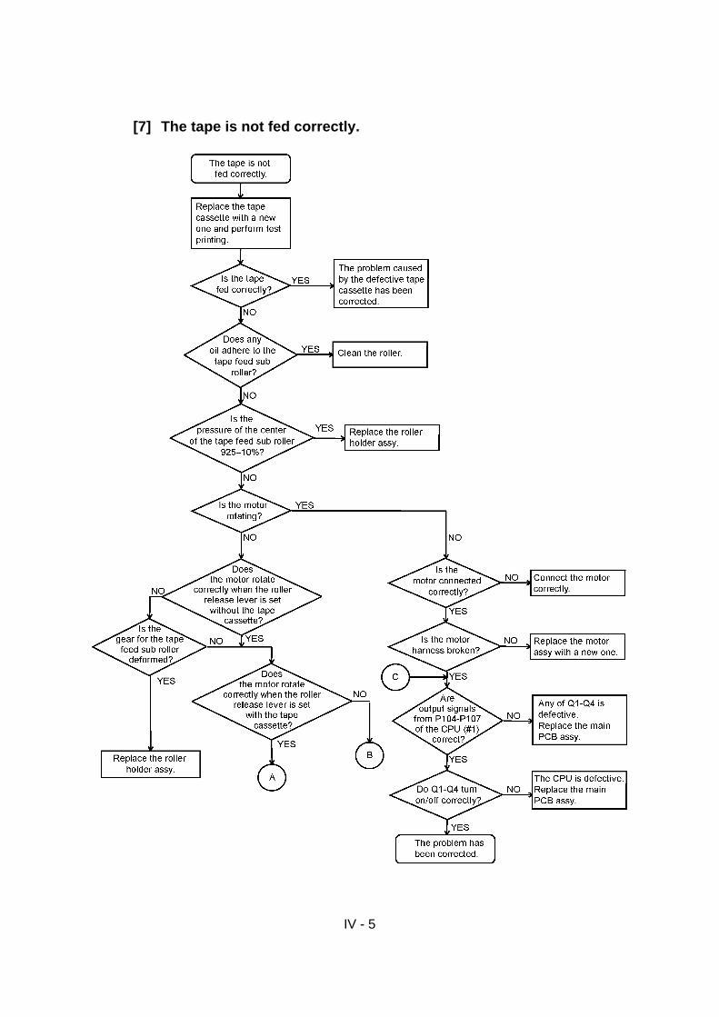
IV - 5
[7] The tape is not fed correctly.

IV - 6

IV - 7
[8] Half-cut is not possible.

IV - 8
[9] The tape is not ejected forcibly.

APPENDIX
Circuit Diagram
Main PCBPower Supply PCB (100-120V)Power Supply PCB (230V)

CONTENTS
APPENDIX
Main (Control) PCB Circuit USB...................................................................................................... APP-1
Power Supply PCB Circuit,100-120V............................................................................................... APP-2
Power Supply PCB Circuit 230V...................................................................................................... APP-3
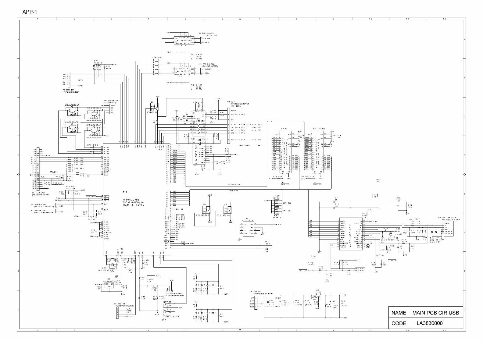


Sep., 20005V2106BE0Printed in Japan