brushbull rotary cutter bb48, bb60, bb72, and bb84
TRANSCRIPT

OP
ER
AT
OR
'S M
AN
UA
L
2-ISO2-ISO
BRUSHBULLROTARY CUTTER
MA
N00
50R
ev.1
0/27
/200
6
Tested. Proven. Unbeatable.
BB48BB60BB72BB84
S/N 994127 & AFTERIncludes Service & Parts Information
for S/N 994126 & Prior
TM
ii Introduction Gen’l (Rev. 5/23/2005)
TO THE DEALER:
Assembly and proper installation of this product is the responsibility of the Woods® dealer. Read manual instructionsand safety rules. Make sure all items on the Dealer’s Pre-Delivery and Delivery Check Lists in the Operator’s Manualare completed before releasing equipment to the owner.
The dealer must complete the Product Registration included with the Operator’s Manual. The customer must sign theregistration which certifies that all Dealer Check List items have been completed. The dealer is to return the prepaidpostage portion to Woods, give one copy to the customer, and retain one copy. Failure to complete and return thiscard does not diminish customer’s warranty rights.
TO THE OWNER:
Read this manual before operating your Woods equipment. The information presented will prepare you to do a better andsafer job. Keep this manual handy for ready reference. Require all operators to read this manual carefully and becomeacquainted with all adjustment and operating procedures before attempting to operate. Replacement manuals can beobtained from your dealer. To locate your nearest dealer, check the Dealer Locator at www.WoodsEquipment.com, or inthe United States and Canada call 1-800-319-6637.
The equipment you have purchased has been carefully engineered and manufactured to provide dependable andsatisfactory use. Like all mechanical products, it will require cleaning and upkeep. Lubricate the unit as specified.Observe all safety information in this manual and safety decals on the equipment.
For service, your authorized Woods dealer has trained mechanics, genuine Woods service parts, and the necessarytools and equipment to handle all your needs.
Use only genuine Woods service parts. Substitute parts will void the warranty and may not meet standards required forsafe and satisfactory operation. Record the model number and serial number of your equipment in the spacesprovided:
Model: _______________________________ Date of Purchase: _____________________
Serial Number: (see Safety Decal section for location) ____________________________________
Provide this information to your dealer to obtain correct repair parts.
Throughout this manual, the term IMPORTANT is used to indicate that failure to observe can cause damage toequipment. The terms CAUTION, WARNING, and DANGER are used in conjunction with the Safety-Alert Symbol (atriangle with an exclamation mark) to indicate the degree of hazard for items of personal safety.
CAUTIONCAUTION
IMPORTANTIMPORTANT
WARNINGWARNING
DANGERDANGER
NOTENOTE
This Safety-Alert Symbol indicates a hazard and means ATTENTION!BECOME ALERT! YOUR SAFETY IS INVOLVED!
Indicates an imminently hazardous situation that, if not avoided, will result in death or serious injury.
Indicates a potentially hazardous situation that, if not avoided, could result in death or serious injury, and includes hazards that are exposed when guards are removed.
Indicates a potentially hazardous situation that, if not avoided, may result in minor or moderate injury.
Indicates that failure to observe can cause damage to equipment.
Indicates helpful information.
Introduction 1MAN0050 (Rev. 1/16/2004)
TABLE OF CONTENTS
INTRODUCTION. . . . . . . . . . . . . . . . . . . . . . . . . . . . INSIDE FRONT COVER
SPECIFICATIONS. . . . . . . . . . . . . . . . . . . . . . . . . . . . . . . . . . . . . . . . . . . . . .2
GENERAL INFORMATION . . . . . . . . . . . . . . . . . . . . . . . . . . . . . . . . . . . . . . .2
SAFETY VIDEO ORDER FORM. . . . . . . . . . . . . . . . . . . . . . . . . . . . . . . . . 3A
SAFETY RULES . . . . . . . . . . . . . . . . . . . . . . . . . . . . . . . . . . . . . . . . . . . . . 3-5
SAFETY DECALS . . . . . . . . . . . . . . . . . . . . . . . . . . . . . . . . . . . . . . . . . . . . 6-7
OPERATION . . . . . . . . . . . . . . . . . . . . . . . . . . . . . . . . . . . . . . . . . . . . . . . . . .8
OWNER SERVICE . . . . . . . . . . . . . . . . . . . . . . . . . . . . . . . . . . . . . . . . . . . .12
TROUBLE SHOOTING . . . . . . . . . . . . . . . . . . . . . . . . . . . . . . . . . . . . . . . . .17
DEALER SERVICE . . . . . . . . . . . . . . . . . . . . . . . . . . . . . . . . . . . . . . . . . . . .18
DEALER CHECK LISTS . . . . . . . . . . . . . . . . . . . . . . . . . . . . . . . . . . . . . . . .27
ASSEMBLY INSTRUCTIONS . . . . . . . . . . . . . . . . . . . . . . . . . . . . . . . . . . . .28
INDEX TO PARTS LISTS . . . . . . . . . . . . . . . . . . . . . . . . . . . . . . . . . . . . . . .35
BOLT TORQUE CHART . . . . . . . . . . . . . . . . . . . . . . . . . . . . . . . . . . . . . . . .50
BOLT SIZE CHART & ABBREVIATIONS . . . . . . . . . . . . . . . . . . . . . . . . . . .51
INDEX . . . . . . . . . . . . . . . . . . . . . . . . . . . . . . . . . . . . . . . . . . . . . . . . . . . . . .52
PRODUCT WARRANTY . . . . . . . . . . . . . . . . . . . . . . . INSIDE BACK COVER
REPLACEMENT PARTS WARRANTY . . . . . . . . . . . . . . . . . . .BACK COVER
Si no lee Ingles, pida ayuda a alguien que si lo lea para que le
traduzca las medidas de seguridad.
LEA EL INSTRUCTIVO!!
(Rev. 10/27/2006)
2 Introduction MAN0050 (Rev. 1/16/2004)
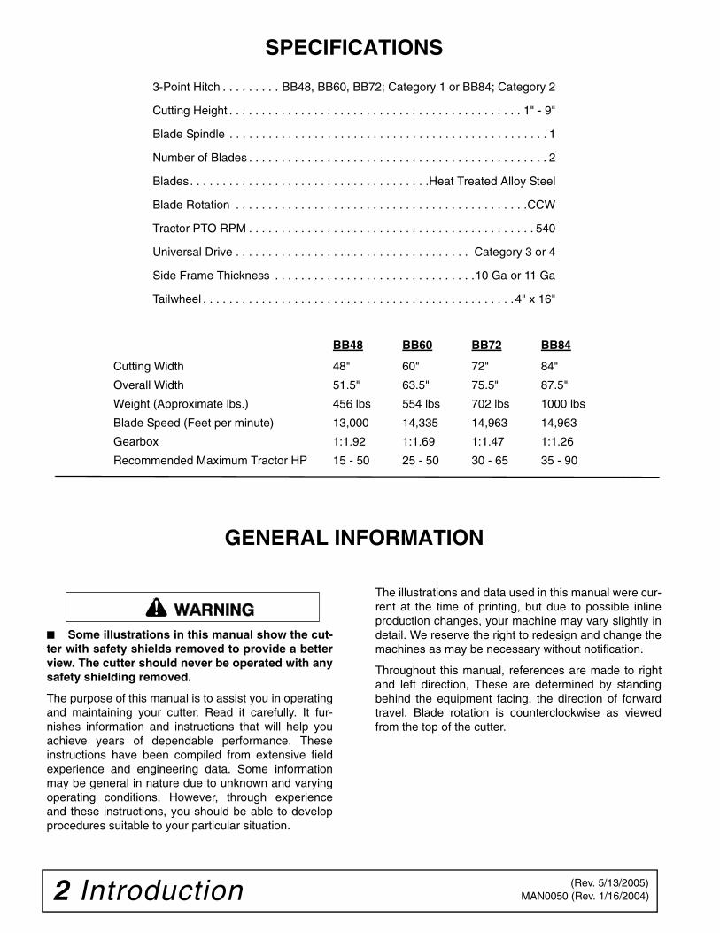
SPECIFICATIONS
3-Point Hitch . . . . . . . . . BB48, BB60, BB72; Category 1 or BB84; Category 2
Cutting Height . . . . . . . . . . . . . . . . . . . . . . . . . . . . . . . . . . . . . . . . . . . . . 1" - 9"
Blade Spindle . . . . . . . . . . . . . . . . . . . . . . . . . . . . . . . . . . . . . . . . . . . . . . . . . 1
Number of Blades . . . . . . . . . . . . . . . . . . . . . . . . . . . . . . . . . . . . . . . . . . . . . . 2
Blades. . . . . . . . . . . . . . . . . . . . . . . . . . . . . . . . . . . . .Heat Treated Alloy Steel
Blade Rotation . . . . . . . . . . . . . . . . . . . . . . . . . . . . . . . . . . . . . . . . . . . . .CCW
Tractor PTO RPM . . . . . . . . . . . . . . . . . . . . . . . . . . . . . . . . . . . . . . . . . . . . 540
Universal Drive . . . . . . . . . . . . . . . . . . . . . . . . . . . . . . . . . . . . Category 3 or 4
Side Frame Thickness . . . . . . . . . . . . . . . . . . . . . . . . . . . . . . .10 Ga or 11 Ga
Tailwheel . . . . . . . . . . . . . . . . . . . . . . . . . . . . . . . . . . . . . . . . . . . . . . . .4" x 16"
GENERAL INFORMATION
■ Some illustrations in this manual show the cut-ter with safety shields removed to provide a betterview. The cutter should never be operated with anysafety shielding removed.
The purpose of this manual is to assist you in operatingand maintaining your cutter. Read it carefully. It fur-nishes information and instructions that will help youachieve years of dependable performance. Theseinstructions have been compiled from extensive fieldexperience and engineering data. Some informationmay be general in nature due to unknown and varyingoperating conditions. However, through experienceand these instructions, you should be able to developprocedures suitable to your particular situation.
The illustrations and data used in this manual were cur-rent at the time of printing, but due to possible inlineproduction changes, your machine may vary slightly indetail. We reserve the right to redesign and change themachines as may be necessary without notification.
Throughout this manual, references are made to rightand left direction, These are determined by standingbehind the equipment facing, the direction of forwardtravel. Blade rotation is counterclockwise as viewedfrom the top of the cutter.
BB48 BB60 BB72 BB84
Cutting Width 48" 60" 72" 84"
Overall Width 51.5" 63.5" 75.5" 87.5"
Weight (Approximate lbs.) 456 lbs 554 lbs 702 lbs 1000 lbs
Blade Speed (Feet per minute) 13,000 14,335 14,963 14,963
Gearbox 1:1.92 1:1.69 1:1.47 1:1.26
Recommended Maximum Tractor HP 15 - 50 25 - 50 30 - 65 35 - 90
�������
(Rev. 5/13/2005)

Safety 3-aSafety Video Order Form (8/2/2005)
Free Mower Safety VideoFill out and return the order form and we will send you a FREE VHSor DVD video outlining Industrial and Agricultural Mower SafetyPractices. The 22 minute video, developed in cooperation withAEM (Association of Equipment Manufacturers), reinforces theproper procedures to follow while operating your Woods mowingequipment. The video does not replace the information contained inthe Operator’s Manual, so please review this manual thoroughlybefore operating your new mowing equipment.
Safety Training Does Make a Difference.
BE SAFE!
BE ALERT!
BE ALIVE!
BE TRAINED Before Operating Mowers!
ASSOCIATION OF EQUIPMENT MANUFACTURERS
3-b Safety Safety Video Order Form (Rev. 2/6/2006)
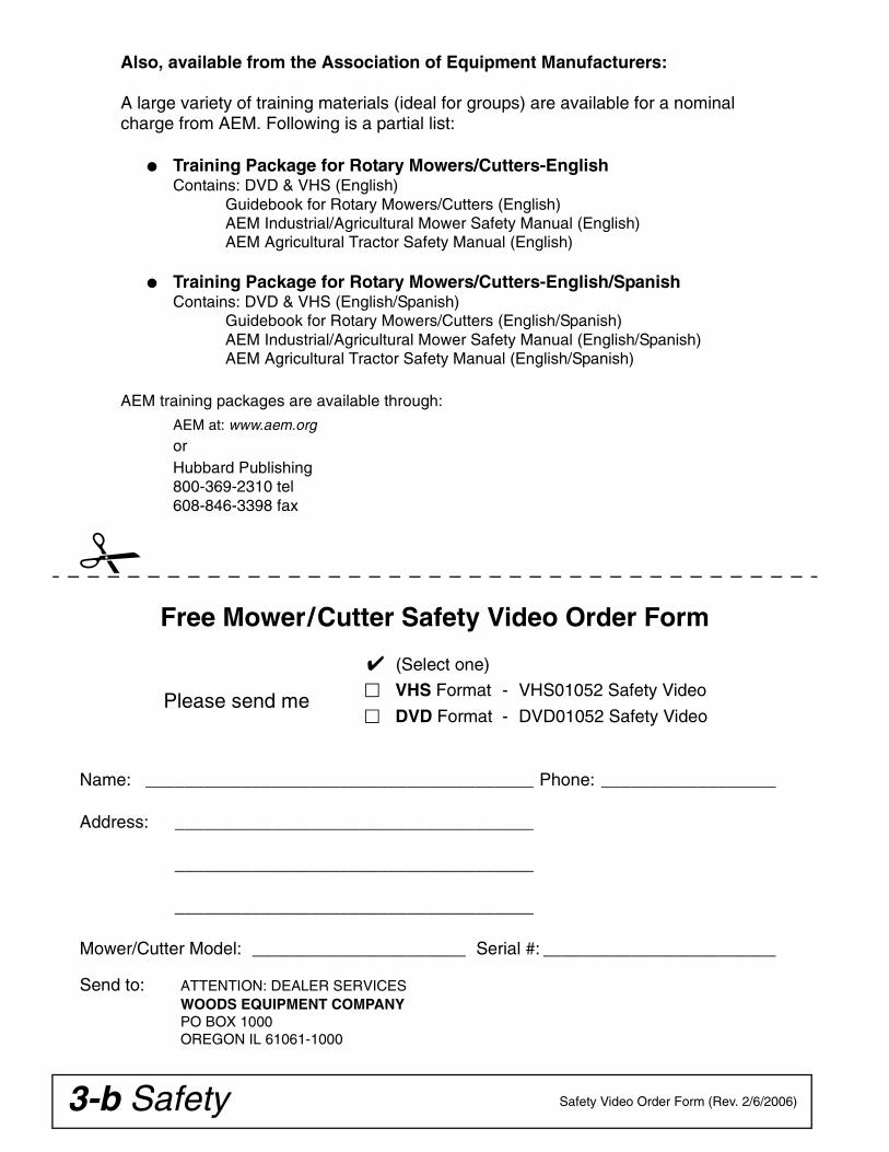
Free Mower/Cutter Safety Video Order Form
✔ (Select one)
VHS Format - VHS01052 Safety Video
DVD Format - DVD01052 Safety Video Please send me
Name: ________________________________________ Phone: __________________
Address: _____________________________________
_____________________________________
_____________________________________
Mower/Cutter Model: ______________________ Serial #: ________________________
Send to: ATTENTION: DEALER SERVICESWOODS EQUIPMENT COMPANYPO BOX 1000OREGON IL 61061-1000
Also, available from the Association of Equipment Manufacturers:
A large variety of training materials (ideal for groups) are available for a nominal charge from AEM. Following is a partial list:
● Training Package for Rotary Mowers/Cutters-English Contains: DVD & VHS (English)
Guidebook for Rotary Mowers/Cutters (English)AEM Industrial/Agricultural Mower Safety Manual (English)AEM Agricultural Tractor Safety Manual (English)
● Training Package for Rotary Mowers/Cutters-English/Spanish Contains: DVD & VHS (English/Spanish)
Guidebook for Rotary Mowers/Cutters (English/Spanish)AEM Industrial/Agricultural Mower Safety Manual (English/Spanish)AEM Agricultural Tractor Safety Manual (English/Spanish)
AEM training packages are available through:
AEM at: www.aem.orgorHubbard Publishing800-369-2310 tel608-846-3398 fax
Safety 3Single Spindle Cutter LD/MD (Rev. 10/27/2006)
TRAINING
Safety instructions are important! Read allattachment and power unit manuals; follow allsafety rules and safety decal information. (Replace-ment manuals and safety decals are available fromyour dealer. To locate your nearest dealer, checkthe Dealer Locator at www.WoodsEquipment.com,or in the United States and Canada call 1-800-319-6637.) Failure to follow instructions or safety rulescan result in serious injury or death.
If you do not understand any part of this manualand need assistance, see your dealer.
Know your controls and how to stop engine andattachment quickly in an emergency.
Operators must be instructed in and be capableof the safe operation of the equipment, its attach-ments, and all controls. Do not allow anyone tooperate this equipment without proper instruc-tions.
Never allow children or untrained persons tooperate equipment.
PREPARATION
Check that all hardware is properly installed.Always tighten to torque chart specificationsunless instructed otherwise in this manual.
Always wear relatively tight and belted clothingto avoid getting caught in moving parts. Wearsturdy, rough-soled work shoes and protectiveequipment for eyes, hair, hands, hearing, and head;and respirator or filter mask where appropriate.
Make sure attachment is properly secured,adjusted, and in good operating condition.
Make sure spring-activated locking pin or collarslides freely and is seated firmly in tractor PTOspline groove.
Make sure driveline guard tether chains areattached to the tractor and equipment as shown inthe pamphlet that accompanies the driveline.Replace if damaged or broken. Check that drivelineguards rotate freely on driveline before puttingequipment into service.
Before starting power unit, check all equipmentdriveline guards for damage. Replace any damagedguards. Make sure all guards rotate freely on alldrivelines. If guards do not rotate freely on drive-lines, repair and replace bearings before puttingequipment into service.
Power unit must be equipped with ROPS orROPS cab and seat belt. Keep seat belt securelyfastened. Falling off power unit can result in deathfrom being run over or crushed. Keep foldableROPS system in “locked up” position at all times.
Inspect chain, rubber, or steel band shieldingbefore each use. Replace if damaged.
Remove accumulated debris from this equip-ment, power unit, and engine to avoid fire hazard.
Make sure all safety decals are installed.Replace if damaged. (See Safety Decals section forlocation.)
Make sure shields and guards are properlyinstalled and in good condition. Replace if dam-aged.
A minimum 20% of tractor and equipmentweight must be on the tractor front wheels whenattachments are in transport position. Without thisweight, tractor could tip over, causing personalinjury or death. The weight may be attained with aloader, front wheel weights, ballast in tires or fronttractor weights. Weigh the tractor and equipment.Do not estimate.
Inspect and clear area of stones, branches, orother hard objects that might be thrown, causinginjury or damage.
OPERATION
Do not allow bystanders in the area when oper-ating, attaching, removing, assembling, or servic-ing equipment.
(Safety Rules continued on next page)
Safety is a primary concern in the design andmanufacture of our products. Unfortunately, ourefforts to provide safe equipment can be wipedout by an operator’s single careless act.
In addition to the design and configuration ofequipment, hazard control and accident preven-tion are dependent upon the awareness, con-cern, judgement, and proper training ofpersonnel involved in the operation, transport,maintenance, and storage of equipment.
It has been said, “The best safety device is aninformed, careful operator.” We ask you to bethat kind of operator.
SAFETY RULESATTENTION! BECOME ALERT! YOUR SAFETY IS INVOLVED!
4 Safety Single Spindle Cutter LD/MD (Rev. 10/27/2006)
(Safety Rules continued from previous page)
Full chain, rubber, or steel band shielding,designed to reduce the possibility of thrownobjects, must be installed when operating in popu-lated areas or other areas where thrown objectscould injure people or damage property. If thismachine is not equipped with full chain, rubber, orsteel band shielding, operation must be stoppedwhen anyone comes within several hundred feet.
Never direct discharge toward people, animals,or property.
Do not operate or transport equipment whileunder the influence of alcohol or drugs.
Operate only in daylight or good artificial light.
Keep hands, feet, hair, and clothing away fromequipment while engine is running. Stay clear of allmoving parts.
Always comply with all state and local lightingand marking requirements.
Never allow riders on power unit or attachment.
Power unit must be equipped with ROPS orROPS cab and seat belt. Keep seat belt securelyfastened. Falling off power unit can result in deathfrom being run over or crushed. Keep foldableROPS system in “locked up” position at all times.
Always sit in power unit seat when operatingcontrols or starting engine. Securely fasten seatbelt, place transmission in neutral, engage brake,and ensure all other controls are disengagedbefore starting power unit engine.
Operate tractor PTO at 540 RPM. Do not exceed.
Do not operate PTO during transport.
Look down and to the rear and make sure areais clear before operating in reverse.
Do not operate or transport on steep slopes.
Do not stop, start, or change directions sud-denly on slopes.
Use extreme care and reduce ground speed onslopes and rough terrain.
Watch for hidden hazards on the terrain duringoperation.
Stop power unit and equipment immediatelyupon striking an obstruction. Turn off engine,remove key, inspect, and repair any damage beforeresuming operation.
Leak down or failure of mechanical or hydraulicsystem can cause equipment to drop.
Before performing any service or maintenance,disconnect driveline from tractor PTO.
MAINTENANCE
Before performing any service or maintenance,disconnect driveline from tractor PTO.
Before working underneath, disconnect drive-line, raise cutter, and block cutter securely. Hydrau-lic system leak down and failure of mechanical orhydraulic system can cause equipment to drop.
Do not modify or alter or permit anyone else tomodify or alter the equipment or any of its compo-nents in any way.
Always wear relatively tight and belted clothingto avoid getting caught in moving parts. Wearsturdy, rough-soled work shoes and protectiveequipment for eyes, hair, hands, hearing, and head;and respirator or filter mask where appropriate.
Make sure attachment is properly secured,adjusted, and in good operating condition.
Do not allow bystanders in the area when oper-ating, attaching, removing, assembling, or servic-ing equipment.
Keep all persons away from operator controlarea while performing adjustments, service, ormaintenance.
Make certain all movement of equipment com-ponents has stopped before approaching for ser-vice.
Frequently check blades. They should be sharp,free of nicks and cracks, and securely fastened.
Do not handle blades with bare hands. Carelessor improper handling may result in serious injury.
Your dealer can supply genuine replacementblades. Substitute blades may not meet originalequipment specifications and may be dangerous.
Tighten all bolts, nuts, and screws to torquechart specifications. Check that all cotter pins areinstalled securely to ensure equipment is in a safecondition before putting unit into service.
Make sure all safety decals are installed.Replace if damaged. (See Safety Decals section forlocation.)
SAFETY RULESATTENTION! BECOME ALERT! YOUR SAFETY IS INVOLVED!

Safety 5Single Spindle Cutter LD/MD (Rev. 10/27/2006)
Make sure shields and guards are properlyinstalled and in good condition. Replace if dam-aged.
Leak down or failure of mechanical or hydraulicsystem can cause equipment to drop.
STORAGEKeep children and bystanders away from stor-
age area.
Disconnect cutter driveshaft and secure up offground. Raise cutter with 3-point hitch. Placeblocks under cutter side skids. Lower cutter ontoblocks. Disconnect cutter from tractor 3-point hitchand carefully drive tractor away from cutter.
SAFETY RULESATTENTION! BECOME ALERT! YOUR SAFETY IS INVOLVED!

6 Safety MAN0050 (Rev. 1/16/2004)
CD6332C
810
6
6
12
12
2
1
7
1 - SERIAL NUMBER PLATE
ROTATING BLADES AND THROWN OBJECTS
� Do not put hands or feet under or into mower when engine is running.
� Before mowing, clear area of objects that may be thrown by blade.
� Keep bystanders away.
� Keep guards in place and in good condition.
BLADE CONTACT OR THROWN OBJECTS CAN CAUSE SERIOUS INJURY OR DEATH.
DANGER
ROTATING DRIVELINE
CONTACT CAN CAUSE DEATH
KEEP AWAY!
DO NOT OPERATE WITHOUT -
� All driveline guards, tractor and equipment shields in place
� Drivelines securely attached at both ends
� Driveline guards that turn freely on driveline
1006682-A
DANGER
8 - PN 1006682
6 – PN 20106RED REFLECTOR 4.5"
12 - PN 57123RED REFLECTOR 9"
MODEL NO. SERIAL NO.
Woods Equipment CompanyOregon, Illinois, U.S.A.
SAFETY & INSTRUCTIONAL DECALSATTENTION! BECOME ALERT! YOUR SAFETY IS INVOLVED!
Replace Immediately If Damaged!
(Rev. 8/19/2005)

Safety 7MAN0050 (Rev. 1/16/2004)
7 - PN 1004114
10 - PN 33347
����� ������
�� �� � �����
�����
33347E
�����
�����
����� ������
�� �� � �����
BE CAREFUL!
Use a clean, damp cloth to clean safety decals.
Avoid spraying too close to decals when using a pressure washer; high-pressure water can enter through very small scratches or under edges of decals causing them to peel or come off.
Replacement safety decals can be ordered free from your Woods dealer. To locate your nearest dealer, check the Dealer Locator at www.WoodsEquipment.com, or in the United States and Canada call 1-800-319-6637.
CRUSHING AND PINCHING HAZARD
� Be extremely careful handling various parts of the machine. They are heavy and hands, fingers, feet, and other body parts could be crushed or pinched between tractor and implement.
� Operate tractor controls from tractor seat only.
� Do not stand between tractor and implement when tractor is in gear.
� Make sure parking brake is engaged before going between tractor and implement.
� Stand clear of machine while in operation or when it is being raised or lowered.
FAILURE TO FOLLOW THESE INSTRUCTIONS COULD RESULT IN SERIOUS INJURY OR DEATH.
WARNING
TO AVOID SERIOUS INJURY OR DEATH:
� Read Operator's Manual (available from dealer) and follow all safety precautions.
� Keep all shields in place and in good condition.
� Operate mower from tractor seat only.
� Lower mower, stop engine and remove key before dismounting tractor.
� Allow no children or untrained persons to operate equipment.
� Do not transport towed or semi-mounted units over 20 mph.
FAILURE TO OPERATE SAFELY CAN RESULT IN INJURY OR DEATH.
WARNING
WARNING
FALLING OFF CAN RESULT IN BEING RUN OVER.
� Tractor must be equipped with ROPS (or ROPS CAB) and seat belt. Keep foldable ROPS systems in "locked up" position at all times.
� Buckle Up! Keep seat belt securely fastened.
� Allow no riders.
RAISED EQUIPMENT CAN DROP AND CRUSH.
� Before working underneath, follow all instructions and safety rules in operator's manual and securely block up all corners of equipment with jack stands.
� Securely blocking prevents equipment from dropping from hydraulic leakdown, hydraulic system failures or mechanical component failures.
FALLING OFF OR FAILING TO BLOCK SECURELY CAN RESULT IN SERIOUS INJURY OR DEATH.
1006681
WARNINGDO NOT EXCEED PTO SPEED OF
540 RPMPTO speeds higher than 540 RPM can cause
equipment failure and personal injury.
2 - 1006681
If shaft connection is visible, shield is missing. Replace shield before operating equipment.
DANGNGERER
1004114
SAFETY & INSTRUCTIONAL DECALSATTENTION! BECOME ALERT! YOUR SAFETY IS INVOLVED!
Replace Immediately If Damaged!
(Rev. 5/13/2005)

8 Operation MAN0050 (Rev. 8/19/2005)
OPERATIONThe operator is responsible for the safe operation ofthe cutter. The operator must be properly trained.Operators should be familiar with the cutter, the tractor,and all safety practices before starting operation. Readthe safety rules and safety decals on pages 3 to 7.
This standard-duty cutter is designed for grass andweed mowing and shredding.
Recommended mowing speed for most conditions isfrom 2 to 5 mph.
Full chain, rubber, or steel band shielding,designed to reduce the possibility of thrownobjects, must be installed when operating in popu-lated areas or other areas where thrown objectscould injure people or damage property. If thismachine is not equipped with full chain, rubber, orsteel band shielding, operation must be stoppedwhen anyone comes within several hundred feet.
Never allow riders on power unit or attachment.
Keep bystanders away from equipment.
Make sure spring-activated locking pin or collarslides freely and is seated firmly in tractor PTOspline groove.
Operate tractor PTO at 540 RPM. Do not exceed.
Stop power unit and equipment immediatelyupon striking an obstruction. Turn off engine,remove key, inspect, and repair any damage beforeresuming operation.
Always wear relatively tight and belted clothingto avoid getting caught in moving parts. Wearsturdy, rough-soled work shoes and protectiveequipment for eyes, hair, hands, hearing, and head;and respirator or filter mask where appropriate.
TRACTOR STABILITY
A minimum 20% of tractor and equipmentweight must be on the tractor front wheels whenattachments are in transport position. Without thisweight, tractor could tip over, causing personalinjury or death. The weight may be attained with a
loader, front wheel weights, ballast in tires or fronttractor weights. Weigh the tractor and equipment.Do not estimate.
Figure 1. Tractor Stability
ATTACH CUTTER TO TRACTOR
Make sure spring-activated locking pin or collarslides freely and is seated firmly in tractor PTOspline groove.
■ Make sure driveline will not bottom out at theshortest length and that it has at least 1/3 overlapat the longest length.
■ With cutter adjusted to transport position, setupper stop on tractor lift quadrant to prevent cutterfrom contacting the driveline when being raised.
■ Select a top link mounting pin (maximumlength 3-5/8") that will allow floating link to swingfreely through the cutter A-frame bars.
1. Attach tractor 3-point lift arms to the cutter hitchpins and secure.
2. Attach tractor top link to cutter clevis using forwardhole. Select a top link mounting pin that will allowfloating link to swing freely through the cutter A-frame bars.
NOTE: You will need to adjust the top link; refer toAdjust Top Link, page 9.
3. Connect driveline to tractor PTO shaft.
NOTE: The standard 1-3/8" 6B spline driveline witha QD yoke is used to connect the cutter to the trac-tor.
4. Adjust the tractor lower 3-point arm anti-swaydevices to prevent cutter from swinging side to sideduring transport.
5. Adjust tractor drawbar so that it will not interferewith cutter or driveline.
6. Slowly raise and lower cutter to check drivelinelength.
������
�������
CAUTION
�������
CD1564
�������
(Rev. 12/2/2005)

Operation 9MAN0050 (Rev. 8/19/2005)
SHREDDING MATERIALFor shredding, set the cutter lower at rear. Determinehow much lower to set the rear by experimenting in dif-ferent situations.
ADJUST CUTTING HEIGHT
Keep all persons away from operator controlarea while performing adjustments, service, ormaintenance.
■ Avoid low cutting heights. Striking the groundwith blades produces one of the most damagingshock loads a cutter can encounter. Allowingblades to contact ground repeatedly will causedamage to cutter and drive.
1. Level cutter from side to side. Check by measuringfrom cutter frame to the ground at each deck rail.
2. Adjust, using tractor 3-point arm leveling device.
NOTE: Keep the front of cutter slightly lower thanrear for best mowing.
3. Control cutting height with tractor 3-point arms,rear tailwheel adjustment, or optional check chains.
4. To raise rear of cutter, move tailwheel arm down.
5. To raise front of cutter, raise tractor 3-point arms orshorten optional check chains.
The cutting height is the distance between the bladeand the ground. The blades are approximately 8.5"below the deck. To check cutting height, do the follow-ing:
a) Place a straight edge along top edge of deck.b) Select a cutting height; as an example, for an
approximate cutting height of 3", set the center ofthe deck 11.5" above the ground:
c) Adjust the front-to-rear attitude from 1/2" to 3/4"higher than the front.
ADJUST TOP LINK
Refer to Figure 2.
IMPORTANT■ When cutter is adjusted to transport position,set upper stop on tractor lift quadrant to preventcutter from contacting the driveline when beingraised.
IMPORTANT■ Select a top link mounting pin (maximumlength 3-5/8") that will allow floating link to swingfreely through the cutter A-frame bars.
1. Attach tractor top link (1) to lowest hole provided inthe tractor’s top link bracket (6).
2. Attach rear portion of tractor top link to the first holeon the cutter floating link (3). Select a top linkmounting pin that will allow the floating link toswing freely through the cutter A-frame bars (5).
3. Raise cutter to transport position and adjust tractortop link until cutter is level in the raised position.
NOTE: If you cannot level the cutter using the low-est hole in the tractor’s top link bracket, move toplink to the next hole and level the cutter.
Figure 2. Top Link Adjustment(BB72 and BB84 Shown)
ATTACH QUICK HITCH
Refer to Figure 4.
IMPORTANT■ When cutter is adjusted to transport position,set upper stop on tractor lift quadrant to preventcutter from contacting the driveline when beingraised.
1. Remove brace arms (6), floating link (3), cap screw(11), spacer (7), and flange lock nut (9) from upperhole on A-frame bars (5) as shown in Figure 4.
NOTE: A-frame bar(s) are installed to mast plateswith carriage bolts through the square holes.
�������
3" Desired cutting height+ 8.5" Distance blade cutting edge is below deck
= 11.5"
1. Tractor top link
2. Cutter top link mounting pin
3. Floating link
4. Cutter hitch pin
5. A-Frame bars
6. Tractor top link bracket
1
2
3
4
LA2
5
6

10 Operation MAN0050 (Rev. 8/19/2005)
2. Attach open end of floating link (3) to the bottomhole of A-frame bars (5). Secure using cap screw(11), sleeve (10), and flange lock nut (9).
3. Attach closed end of floating link (3) to diagonalbraces (6). Secure using cap screw (8), spacer (7),and flange lock nut (9) supplied in hardware bag.
NOTE: Quick hitch top hook will pick up on sleeve(10). Lower quick hitch hook will attach to cutterhitch pins.
4. Raise cutter to transport position and adjust tractortop link until cutter is level in the raised position.
INSTALLATION AND REMOVAL OF DRIVELINE (TRACTOR PTO)
To Install:Pull locking collar back and at the same time push driv-eline onto tractor PTO shaft until locking deviceengages.
To Remove:Hold driveline into position, pull locking collar back, andslide driveline off tractor PTO shaft.
Figure 3. Lock Collar
Figure 4. Standard Hitch and Quick Hitch Configuration
10
3
3
5
5
5
5
6
6
6
6
8
7
9
9
10
11
11
7
Standard Hitch Configuration
Quick Hitch Configuration
CD6316
3. Floating link5. A-frame6. Diagonal braces7. 1/2 x 2-3/4 Spacer
8. 1/2 NC x 4 Cap screw9. 1/2 NC Flange lock nut
10. 1/2 x 3/4 x 2-13/16 Sleeve11. 1/2 NC x 5 Cap screw
(Rev. 12/2/2005)
Operation 11MAN0050 (Rev. 8/19/2005)
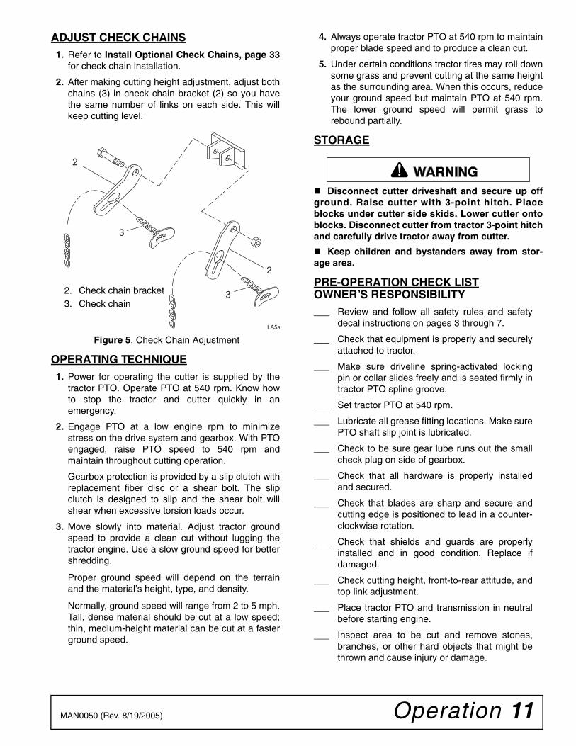
ADJUST CHECK CHAINS1. Refer to Install Optional Check Chains, page 33
for check chain installation.
2. After making cutting height adjustment, adjust bothchains (3) in check chain bracket (2) so you havethe same number of links on each side. This willkeep cutting level.
Figure 5. Check Chain Adjustment
OPERATING TECHNIQUE1. Power for operating the cutter is supplied by the
tractor PTO. Operate PTO at 540 rpm. Know howto stop the tractor and cutter quickly in anemergency.
2. Engage PTO at a low engine rpm to minimizestress on the drive system and gearbox. With PTOengaged, raise PTO speed to 540 rpm andmaintain throughout cutting operation.
Gearbox protection is provided by a slip clutch withreplacement fiber disc or a shear bolt. The slipclutch is designed to slip and the shear bolt willshear when excessive torsion loads occur.
3. Move slowly into material. Adjust tractor groundspeed to provide a clean cut without lugging thetractor engine. Use a slow ground speed for bettershredding.
Proper ground speed will depend on the terrainand the material’s height, type, and density.
Normally, ground speed will range from 2 to 5 mph.Tall, dense material should be cut at a low speed;thin, medium-height material can be cut at a fasterground speed.
4. Always operate tractor PTO at 540 rpm to maintainproper blade speed and to produce a clean cut.
5. Under certain conditions tractor tires may roll downsome grass and prevent cutting at the same heightas the surrounding area. When this occurs, reduceyour ground speed but maintain PTO at 540 rpm.The lower ground speed will permit grass torebound partially.
STORAGE
Disconnect cutter driveshaft and secure up offground. Raise cutter with 3-point hitch. Placeblocks under cutter side skids. Lower cutter ontoblocks. Disconnect cutter from tractor 3-point hitchand carefully drive tractor away from cutter.
Keep children and bystanders away from stor-age area.
PRE-OPERATION CHECK LISTOWNER’S RESPONSIBILITY___ Review and follow all safety rules and safety
decal instructions on pages 3 through 7.
___ Check that equipment is properly and securelyattached to tractor.
___ Make sure driveline spring-activated lockingpin or collar slides freely and is seated firmly intractor PTO spline groove.
___ Set tractor PTO at 540 rpm.
___ Lubricate all grease fitting locations. Make surePTO shaft slip joint is lubricated.
___ Check to be sure gear lube runs out the smallcheck plug on side of gearbox.
___ Check that all hardware is properly installedand secured.
___ Check that blades are sharp and secure andcutting edge is positioned to lead in a counter-clockwise rotation.
___ Check that shields and guards are properlyinstalled and in good condition. Replace ifdamaged.
___ Check cutting height, front-to-rear attitude, andtop link adjustment.
___ Place tractor PTO and transmission in neutralbefore starting engine.
___ Inspect area to be cut and remove stones,branches, or other hard objects that might bethrown and cause injury or damage.
2
3
3
2
LA5a
2. Check chain bracket3. Check chain
�������

12 Owner Service MAN0050 (Rev. 1/16/2004)
OWNER SERVICEThe information in this section is written for operatorswho possess basic mechanical skills. If you need help,your dealer has trained service technicians available.For your protection, read and follow the safety informa-tion in this manual
Keep all persons away from operator controlarea while performing adjustments, service, ormaintenance.
If you do not understand any part of this manualand need assistance, see your dealer.
Always wear relatively tight and belted clothingto avoid getting caught in moving parts. Wearsturdy, rough-soled work shoes and protectiveequipment for eyes, hair, hands, hearing, and head;and respirator or filter mask where appropriate.
BLOCKING METHOD
Before performing any service or maintenance,disconnect driveline from tractor PTO.
Never go underneath equipment (lowered to theground or raised) unless it is properly blocked andsecured. Never place any part of the body under-neath equipment or between moveable parts evenwhen the engine has been turned off. Hydraulicsystem leak down, hydraulic system failures,
mechanical failures, or movement of control leverscan cause equipment to drop or rotate unexpect-edly and cause severe injury or death. Follow Oper-ator's Manual instructions for working underneathand blocking requirements or have work done by aqualified dealer.
To minimize the potential hazards of workingunderneath the cutter, follow these procedures.
1. Jackstands with a load rating of 1000 lbs. or moreare the only approved blocking device for thiscutter. Install a minimum of four jackstands (shownby Xs in Figure 5) under the cutter before workingunderneath unit.
Do not position jackstands under wheels, axles, orwheel supports. Components can rotate and causecutter to fall.
2. Consider the overall stability of the blocked unit.Just placing jackstands underneath will not ensureyour safety.
The working surface must be level and solid tosupport the weight on the jackstands. Make surejackstands are stable, both top and bottom. Makesure cutter is approximately level.
3. With full cutter weight lowered onto jackstands, testblocking stability before working underneath.
4. If cutter is attached to tractor when blocking, setthe brakes, remove key, and block cutter beforeworking underneath.
5. Securely block rear tractor wheels, in front andbehind. Tighten tractor lower 3-point arm anti-swaymechanism to prevent side-to-side movement.
�������
CAUTION
�������
(Rev. 8/19/2005)
Owner Service 13MAN0050 (Rev. 1/16/2004)
LUBRICATION INFORMATION1. Do not let excess grease collect on or around
parts, particularly when operating in sandy areas.
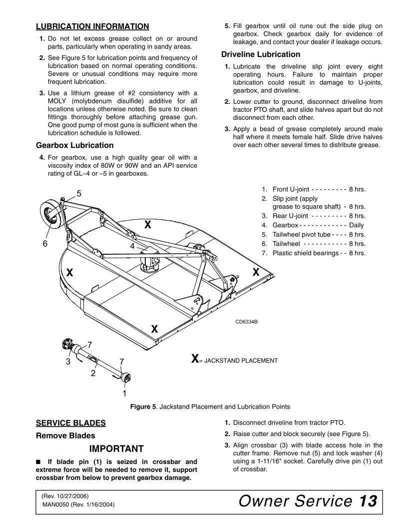
2. See Figure 5 for lubrication points and frequency oflubrication based on normal operating conditions.Severe or unusual conditions may require morefrequent lubrication.
3. Use a lithium grease of #2 consistency with aMOLY (molybdenum disulfide) additive for alllocations unless otherwise noted. Be sure to cleanfittings thoroughly before attaching grease gun.One good pump of most guns is sufficient when thelubrication schedule is followed.
Gearbox Lubrication4. For gearbox, use a high quality gear oil with a
viscosity index of 80W or 90W and an API servicerating of GL–4 or –5 in gearboxes.
5. Fill gearbox until oil runs out the side plug ongearbox. Check gearbox daily for evidence ofleakage, and contact your dealer if leakage occurs.
Driveline Lubrication1. Lubricate the driveline slip joint every eight
operating hours. Failure to maintain properlubrication could result in damage to U-joints,gearbox, and driveline.
2. Lower cutter to ground, disconnect driveline fromtractor PTO shaft, and slide halves apart but do notdisconnect from each other.
3. Apply a bead of grease completely around malehalf where it meets female half. Slide drive halvesover each other several times to distribute grease.
Figure 5. Jackstand Placement and Lubrication Points
SERVICE BLADES
Remove Blades
IMPORTANT■ If blade pin (1) is seized in crossbar andextreme force will be needed to remove it, supportcrossbar from below to prevent gearbox damage.
1. Disconnect driveline from tractor PTO.
2. Raise cutter and block securely (see Figure 5).
3. Align crossbar (3) with blade access hole in thecutter frame. Remove nut (5) and lock washer (4)using a 1-11/16" socket. Carefully drive pin (1) outof crossbar.
CD6334B
23
1
7
7
6
5
4
1. Front U-joint - - - - - - - - - 8 hrs.2. Slip joint (apply
grease to square shaft) - 8 hrs.3. Rear U-joint - - - - - - - - - 8 hrs.4. Gearbox - - - - - - - - - - - - Daily5. Tailwheel pivot tube - - - - 8 hrs.6. Tailwheel - - - - - - - - - - - 8 hrs.7. Plastic shield bearings - - 8 hrs.
X= JACKSTAND PLACEMENT
X
X
X
X
(Rev. 10/27/2006)
14 Owner Service MAN0050 (Rev. 1/16/2004)
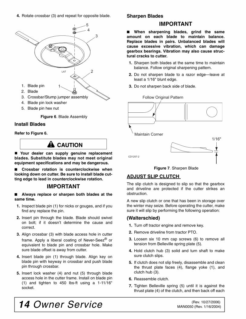
4. Rotate crossbar (3) and repeat for opposite blade.
Figure 6. Blade Assembly
Install Blades
Refer to Figure 6.
Your dealer can supply genuine replacementblades. Substitute blades may not meet originalequipment specifications and may be dangerous.
■ Crossbar rotation is counterclockwise whenlooking down on cutter. Be sure to install blade cut-ting edge to lead in counterclockwise rotation.
IMPORTANT■ Always replace or sharpen both blades at thesame time.
1. Inspect blade pin (1) for nicks or gouges, and if youfind any replace the pin.
2. Insert pin through the blade. Blade should swivelon bolt; if it doesn’t determine the cause andcorrect.
3. Align crossbar (3) with blade access hole in cutter
frame. Apply a liberal coating of Never-Seez® orequivalent to blade pin and crossbar hole. Makesure blade offset is away from cutter.
4. Insert blade pin (1) through blade. Align key onblade pin with keyway in crossbar and push bladepin through crossbar.
5. Insert lock washer (4) and nut (5) through bladeaccess hole in the cutter frame. Install on blade pin(1) and tighten to 450 lbs-ft using a 1-11/16"socket.
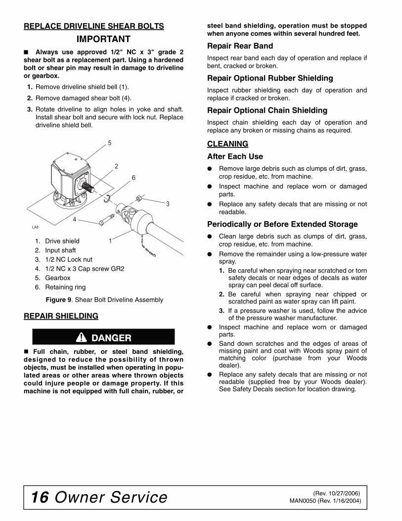
Sharpen Blades
IMPORTANT■ When sharpening blades, grind the sameamount on each blade to maintain balance.Replace blades in pairs. Unbalanced blades willcause excessive vibration, which can damagegearbox bearings. Vibration may also cause struc-tural cracks to cutter.
1. Sharpen both blades at the same time to maintainbalance. Follow original sharpening pattern.
2. Do not sharpen blade to a razor edge—leave atleast a 1/16" blunt edge.
3. Do not sharpen back side of blade.
Figure 7. Sharpen Blade
ADJUST SLIP CLUTCH The slip clutch is designed to slip so that the gearboxand driveline are protected if the cutter strikes anobstruction.
A new slip clutch or one that has been in storage overthe winter may seize. Before operating the cutter, makesure it will slip by performing the following operation:
(Walterschied)1. Turn off tractor engine and remove key.
2. Remove driveline from tractor PTO.
3. Loosen six 10 mm cap screws (6) to remove alltension from Belleville spring plate (5).
4. Hold clutch hub (3) solid and turn shaft to makesure clutch slips.
5. If clutch does not slip freely, disassemble and cleanthe thrust plate faces (4), flange yoke (1), andclutch hub (3).
6. Reassemble clutch.
7. Tighten Belleville spring (5) until it is against thethrust plate (4) of the clutch, and then back off each
1
2
34
5
LA7
1. Blade pin2. Blade3. Crossbar/Stump jumper assembly4. Blade pin lock washer5. Blade pin hex nut
CAUTION1/16"
Follow Original Pattern
Maintain Corner
CD1257-2
(Rev. 10/27/2006)

Owner Service 15MAN0050 (Rev. 1/16/2004)
of the six nuts by two full revolutions. The gapbetween Belleville spring and thrust plate shouldbe 1/8" as shown in Figure 8.
8. If a clutch continues to slip when the spring iscompressed to 1/8", check friction discs (2) forexcessive wear. Discs are 1/8" when new. Replacediscs after 1/16" wear. Minimum disc thickness is1/16".
(Comer)1. Turn off tractor engine and remove key.
2. Loosen nuts on springs until the springs can rotatefreely, yet remain secure on the bolts.
3. Mark outer plates of slip-disc clutch as shown inFigure 8.
4. Securely attach implement to the tractor and startthe tractor.
5. Engage PTO for several seconds then quicklydisengage it.
6. Turn tractor off and remove key.
7. The friction lining plates should have "slipped".Check the marks placed on the outer plates of theslip-disc clutch in step 3 to make sure this is thecase.
8. If clutch does not slip check assembly for oil,grease and debris. Clean if necessary.
9. Reassemble clutch and tighten bolts no more than1/8 of a turn at a time until desired setting of 1.26"as shown in Figure 8.
10. If excessive slippage continues check lining platesfor excessive wear. They are 1/8" thick when newand should be replaced after 1/32" of wear toensure proper operation.
Figure 8. Slip Clutch Assembly
1 2 3 2 4 5
6
7
LA3
1/8"
1. Flange yoke2. Friction disc3. Hub, 1-3/8 round bore4. Thrust plate5. Belleville spring plate6. 10 mm x 1.35P x 50 mm Cap screw7. 10 mm x 1.5P Hex nut
CD7100
12
3 4 3 5 676
1.26
7.09
Outer Plates
1. Flange yoke2. Bushing3. Lining ring4. Flanged hub F125. Pressure plate6. Bolt and nut M10 x 807. Spring
Walterschied Comer
(Rev. 10/27/2006)
16 Owner Service MAN0050 (Rev. 1/16/2004)
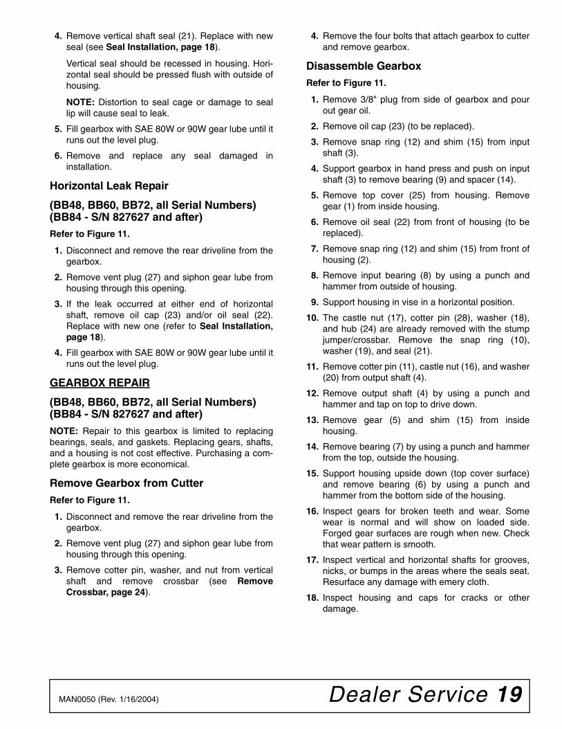
REPLACE DRIVELINE SHEAR BOLTS
IMPORTANT■ Always use approved 1/2" NC x 3" grade 2shear bolt as a replacement part. Using a hardenedbolt or shear pin may result in damage to drivelineor gearbox.
1. Remove driveline shield bell (1).
2. Remove damaged shear bolt (4).
3. Rotate driveline to align holes in yoke and shaft.Install shear bolt and secure with lock nut. Replacedriveline shield bell.
Figure 9. Shear Bolt Driveline Assembly
REPAIR SHIELDING
Full chain, rubber, or steel band shielding,designed to reduce the possibility of thrownobjects, must be installed when operating in popu-lated areas or other areas where thrown objectscould injure people or damage property. If thismachine is not equipped with full chain, rubber, or
steel band shielding, operation must be stoppedwhen anyone comes within several hundred feet.
Repair Rear BandInspect rear band each day of operation and replace ifbent, cracked or broken.
Repair Optional Rubber ShieldingInspect rubber shielding each day of operation andreplace if cracked or broken.
Repair Optional Chain ShieldingInspect chain shielding each day of operation andreplace any broken or missing chains as required.
CLEANING
After Each Use● Remove large debris such as clumps of dirt, grass,
crop residue, etc. from machine.
● Inspect machine and replace worn or damagedparts.
● Replace any safety decals that are missing or notreadable.
Periodically or Before Extended Storage● Clean large debris such as clumps of dirt, grass,
crop residue, etc. from machine.
● Remove the remainder using a low-pressure waterspray.1. Be careful when spraying near scratched or torn
safety decals or near edges of decals as waterspray can peel decal off surface.
2. Be careful when spraying near chipped orscratched paint as water spray can lift paint.
3. If a pressure washer is used, follow the adviceof the pressure washer manufacturer.
● Inspect machine and replace worn or damagedparts.
● Sand down scratches and the edges of areas ofmissing paint and coat with Woods spray paint ofmatching color (purchase from your Woodsdealer).
● Replace any safety decals that are missing or notreadable (supplied free by your Woods dealer).See Safety Decals section for location drawing.
1
2
3
4
5
LA8
6
1. Drive shield2. Input shaft3. 1/2 NC Lock nut4. 1/2 NC x 3 Cap screw GR25. Gearbox6. Retaining ring
������
(Rev. 10/27/2006)

Owner Service 17MAN0050 (Rev. 1/16/2004)
TROUBLE SHOOTING
MOWING CONDITIONS
PROBLEM POSSIBLE CAUSE SOLUTION
Grass cut lower in center of swath than at edge
Height of cutter lower at rear or front
Adjust cutter height and attitude so that cutter rear and front are within 1/2" of same height.
Streaking conditions in swath Conditions too wet for mowing Allow grass to dry before mowing.
Blades unable to cut that part of grass pressed by path of tractor tires
Slow ground speed of tractor but keep engine running at full PTO RPM. Cutting lower will help.
Dull blades Sharpen or replace blades.
Material discharges from cutter unevenly; bunches of material along swath
Material too high and too much material
Reduce ground speed but main-tain 540 RPM at tractor PTO or make two passes over material.Raise cutter for the first pass and lower to desired height for the sec-ond and cut at 90° to first pass. Raise rear of cutter high enough to permit material to discharge but not so high as to cause conditions listed above.
Grass wet Allow grass to dry before mowing. Slow ground speed of tractor but keep engine running at full PTO RPM. Cutting lower will help.
Rear of cutter too low, trapping material under cutter
Adjust cutter height and attitude.
Cutter will not cut(Shear bolt drive only)
Shear bolt sheared Install new shear bolt.
Cutter will not cut all the time(Slip clutch drive only)
Slip clutch slipping Adjust slip clutch according to instructions in Adjust Slip Clutch, page 14.

18 Dealer Service MAN0050 (Rev. 1/16/2004)
DEALER SERVICEThe information in this section is written for dealer ser-vice personnel. The repair described here requiresspecial skills and tools. If your shop is not properlyequipped or your mechanics are not properly trained inthis type of repair, you may be time and money aheadto replace complete assemblies.
Before working underneath, disconnect drive-line, raise cutter, lock in transport position, andblock cutter securely. Hydraulic system leak downand failure of mechanical or hydraulic system cancause equipment to drop.
Keep all persons away from operator controlarea while performing adjustments, service, ormaintenance.
Always wear relatively tight and belted clothingto avoid getting caught in moving parts. Wearsturdy, rough-soled work shoes and protectiveequipment for eyes, hair, hands, hearing, and head;and respirator or filter mask where appropriate.
GEARBOX MAINTENANCENOTE: Read this entire section before starting anyrepair. Many steps are dependent on each other.
1. Fill gearbox with SAE 80W or 90W gear lube until itruns out the side level plug.
NOTE: Repair to this gearbox is limited to replac-ing bearings, seals, and gaskets. Replacing gears,shafts, and a housing is not cost effective. Pur-chasing a complete gearbox is more economical.
2. Inspect gearbox for leakage and bad bearings.Leakage is a very serious problem and must becorrected immediately. Bearing failure is indicatedby excessive noise and side-to-side or end-play ingear shafts.
Seal ReplacementRecommended sealant for gearbox repair is Perma-
tex® Aviation 3D Form-A-Gasket or equivalent.
Leakage can occur at the vertical or horizontal gasketsand shaft seals.
Leakage at the horizontal gasket or seal can berepaired without removing the gearbox from the cutter.
Seal InstallationNOTE: Proper seal installation is important. An improp-erly installed seal will leak.
1. Clean area in housing where seal outer diameter(OD) seats. Apply a thin coat of Permatex.
2. Inspect area of shaft where seal seats. Removeany burrs or nicks with an emery cloth.
3. Lubricate gear shaft and seal lips.
4. Place seal squarely on housing, spring-loaded liptoward housing. Select a piece of pipe or tubingwith an OD that will sit on the outside edge of theseal but will clear the housing. Tubing with an ODthat is too small will bow seal cage and ruin seal.
5. Carefully press seal into housing, avoidingdistortion to the metal seal cage.
Figure 10. Seal Installation
Vertical Shaft Repair
(BB48, BB60, BB72, all Serial Numbers)(BB84 - S/N 827627 and after)Refer to Figure 11.
1. Disconnect and remove the rear driveline from thegearbox.
2. Remove vent plug (27) and siphon gear lube fromhousing through this opening.
3. Remove crossbar (see Remove Crossbar, page24).
�������
CAUTION
1
3
4
2
CD1094
CD1092
1. Seal2. Pipe or tube3. Seal seat4. Casting
Pipe or tube mustpress at outer edgeof seal.
IncorrectInstallation
Dealer Service 19MAN0050 (Rev. 1/16/2004)
4. Remove vertical shaft seal (21). Replace with newseal (see Seal Installation, page 18).
Vertical seal should be recessed in housing. Hori-zontal seal should be pressed flush with outside ofhousing.
NOTE: Distortion to seal cage or damage to seallip will cause seal to leak.
5. Fill gearbox with SAE 80W or 90W gear lube until itruns out the level plug.
6. Remove and replace any seal damaged ininstallation.
Horizontal Leak Repair
(BB48, BB60, BB72, all Serial Numbers)(BB84 - S/N 827627 and after)Refer to Figure 11.
1. Disconnect and remove the rear driveline from thegearbox.
2. Remove vent plug (27) and siphon gear lube fromhousing through this opening.
3. If the leak occurred at either end of horizontalshaft, remove oil cap (23) and/or oil seal (22).Replace with new one (refer to Seal Installation,page 18).
4. Fill gearbox with SAE 80W or 90W gear lube until itruns out the level plug.
GEARBOX REPAIR
(BB48, BB60, BB72, all Serial Numbers)(BB84 - S/N 827627 and after)NOTE: Repair to this gearbox is limited to replacingbearings, seals, and gaskets. Replacing gears, shafts,and a housing is not cost effective. Purchasing a com-plete gearbox is more economical.
Remove Gearbox from CutterRefer to Figure 11.
1. Disconnect and remove the rear driveline from thegearbox.
2. Remove vent plug (27) and siphon gear lube fromhousing through this opening.
3. Remove cotter pin, washer, and nut from verticalshaft and remove crossbar (see RemoveCrossbar, page 24).
4. Remove the four bolts that attach gearbox to cutterand remove gearbox.
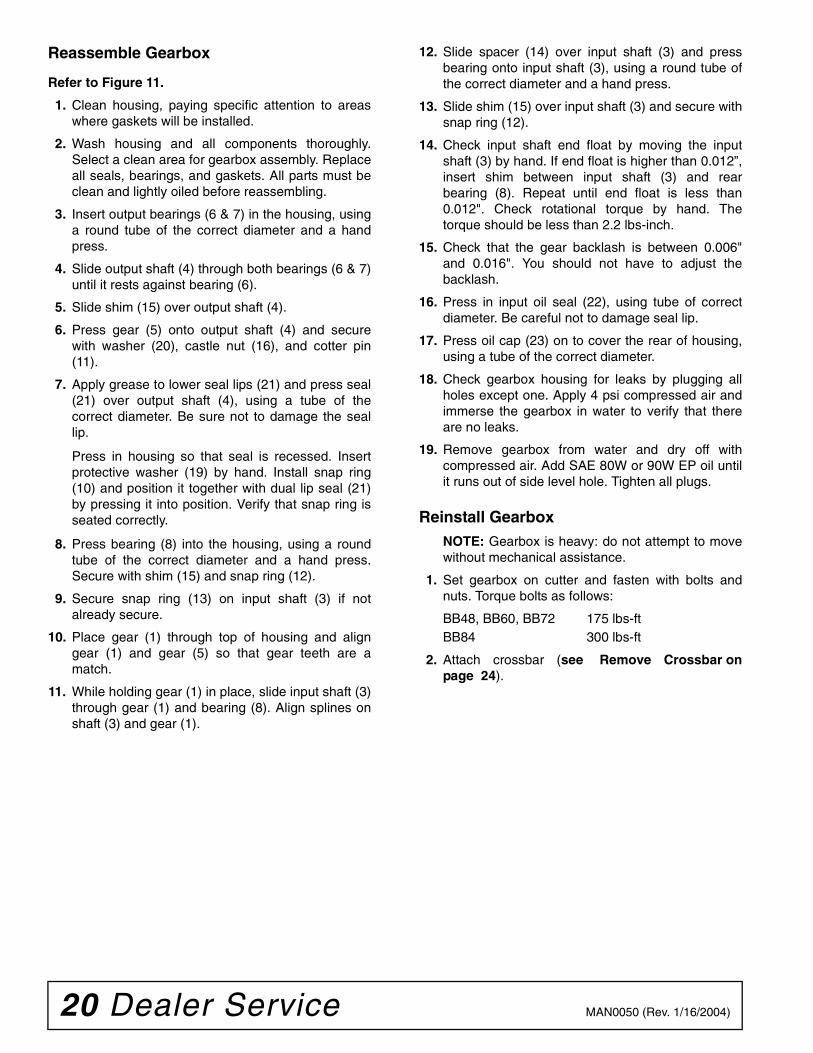
Disassemble GearboxRefer to Figure 11.
1. Remove 3/8" plug from side of gearbox and pourout gear oil.
2. Remove oil cap (23) (to be replaced).
3. Remove snap ring (12) and shim (15) from inputshaft (3).
4. Support gearbox in hand press and push on inputshaft (3) to remove bearing (9) and spacer (14).
5. Remove top cover (25) from housing. Removegear (1) from inside housing.
6. Remove oil seal (22) from front of housing (to bereplaced).
7. Remove snap ring (12) and shim (15) from front ofhousing (2).
8. Remove input bearing (8) by using a punch andhammer from outside of housing.
9. Support housing in vise in a horizontal position.
10. The castle nut (17), cotter pin (28), washer (18),and hub (24) are already removed with the stumpjumper/crossbar. Remove the snap ring (10),washer (19), and seal (21).
11. Remove cotter pin (11), castle nut (16), and washer(20) from output shaft (4).
12. Remove output shaft (4) by using a punch andhammer and tap on top to drive down.
13. Remove gear (5) and shim (15) from insidehousing.
14. Remove bearing (7) by using a punch and hammerfrom the top, outside the housing.
15. Support housing upside down (top cover surface)and remove bearing (6) by using a punch andhammer from the bottom side of the housing.
16. Inspect gears for broken teeth and wear. Somewear is normal and will show on loaded side.Forged gear surfaces are rough when new. Checkthat wear pattern is smooth.
17. Inspect vertical and horizontal shafts for grooves,nicks, or bumps in the areas where the seals seat.Resurface any damage with emery cloth.
18. Inspect housing and caps for cracks or otherdamage.
20 Dealer Service MAN0050 (Rev. 1/16/2004)
Reassemble Gearbox
Refer to Figure 11.
1. Clean housing, paying specific attention to areaswhere gaskets will be installed.
2. Wash housing and all components thoroughly.Select a clean area for gearbox assembly. Replaceall seals, bearings, and gaskets. All parts must beclean and lightly oiled before reassembling.
3. Insert output bearings (6 & 7) in the housing, usinga round tube of the correct diameter and a handpress.
4. Slide output shaft (4) through both bearings (6 & 7)until it rests against bearing (6).
5. Slide shim (15) over output shaft (4).
6. Press gear (5) onto output shaft (4) and securewith washer (20), castle nut (16), and cotter pin(11).
7. Apply grease to lower seal lips (21) and press seal(21) over output shaft (4), using a tube of thecorrect diameter. Be sure not to damage the seallip.
Press in housing so that seal is recessed. Insertprotective washer (19) by hand. Install snap ring(10) and position it together with dual lip seal (21)by pressing it into position. Verify that snap ring isseated correctly.
8. Press bearing (8) into the housing, using a roundtube of the correct diameter and a hand press.Secure with shim (15) and snap ring (12).
9. Secure snap ring (13) on input shaft (3) if notalready secure.
10. Place gear (1) through top of housing and aligngear (1) and gear (5) so that gear teeth are amatch.
11. While holding gear (1) in place, slide input shaft (3)through gear (1) and bearing (8). Align splines onshaft (3) and gear (1).
12. Slide spacer (14) over input shaft (3) and pressbearing onto input shaft (3), using a round tube ofthe correct diameter and a hand press.
13. Slide shim (15) over input shaft (3) and secure withsnap ring (12).
14. Check input shaft end float by moving the inputshaft (3) by hand. If end float is higher than 0.012”,insert shim between input shaft (3) and rearbearing (8). Repeat until end float is less than0.012". Check rotational torque by hand. Thetorque should be less than 2.2 lbs-inch.
15. Check that the gear backlash is between 0.006"and 0.016". You should not have to adjust thebacklash.
16. Press in input oil seal (22), using tube of correctdiameter. Be careful not to damage seal lip.
17. Press oil cap (23) on to cover the rear of housing,using a tube of the correct diameter.
18. Check gearbox housing for leaks by plugging allholes except one. Apply 4 psi compressed air andimmerse the gearbox in water to verify that thereare no leaks.
19. Remove gearbox from water and dry off withcompressed air. Add SAE 80W or 90W EP oil untilit runs out of side level hole. Tighten all plugs.
Reinstall GearboxNOTE: Gearbox is heavy: do not attempt to movewithout mechanical assistance.
1. Set gearbox on cutter and fasten with bolts andnuts. Torque bolts as follows:
BB48, BB60, BB72 175 lbs-ftBB84 300 lbs-ft
2. Attach crossbar (see Remove Crossbar onpage 24).

Dealer Service 21MAN0050 (Rev. 1/16/2004)
Figure 11. Gearbox Assembly(BB48, BB60, BB72 All Serial Numbers)
(BB84–S/N 827627 & After)
1512
22
113
3
14
9
1223
1620
51515A
6
11
4
7
21
19
10
18
17
258
27
15
2
26
CD5753
28
20A
19A
20. Flat washer (BB48, BB60, BB72)20A. Shim kit (BB84)21. Metric seal 40 x 80 x 1222. Oil seal23. Oil cup25. Top cover26. Cap screw 8 mm x 16 (8.8)27. Vent plug28. Cotter pin or 6" Wire, 9 ga.
1. Crown gear2. Gearbox housing3. Input shaft4. Output shaft5. Gear pinion6. Bearing7. Bearing8. Bearing9. Ball bearing 6207
10. Internal retainer ring (BB48, BB60 BB72)
11. Cotter pin12. Snap ring13. Snap ring (BB48, BB60, BB72)14. Spacer 35.3 x 48.25
(BB48, BB60, BB72)15. Shim kit16. Castle nut17. Castle nut metric M24 x 218. Washer19. Protective washer
(BB48, BB60, BB72)19A. Protective screen (BB84)
(Rev. 1/21/2005)

22 Dealer Service MAN0050 (Rev. 1/16/2004)
GEARBOX REPAIR
(BB84 S/N 827626 & Prior)
Disassemble GearboxRefer to Figure 12.
1. Drain oil from gearbox.
2. Remove cover bolts (21) and lock washers (23).
3. Remove front cover plate (16). Remove bearing(13), gasket (15), and seal (14) from cover plate.
4. Remove shaft (11) along with gear (12) andbearing (10).
5. Remove lower cover bolts (22) and lock washers(17) from lower cover plate (1). Remove gasket (2)and seal (3) from bottom cover plate.
6. Remove output shaft along with bearings, gears,and castle nut from gearbox housing.
7. Remove cotter pin (18) and castle nut (24).Remove gear (8). Remove upper bearing cone (5),spacer (6), and lower bearing (5).
8. Remove bearing cone (5) and shims (7) from gear(8).
Reassemble GearboxRefer to Figure 12.
NOTE: Replace all seals, bearings, and gaskets. Allparts must be clean and lubricated before assembling.
1. Insert bearing (10) into gearbox.
2. Reassemble output shaft (4) with bearings (5),spacer (6), gear (8), shims (7), and castle nut (24).
Insert output shaft with bearings into gearboxhousing.
3. Tighten castle nut until shaft rolling torque is 5.5 to13 lbs-inch. Insert cotter pin (18) through nut andshaft.
4. Insert seal (3) into lower cover (1). Place gasket (2)on cover (1), being careful to prevent cutting seallip. Install lower cover output shaft. Install lockwashers (17) and bolts (22). Shaft should not haveany axial play.
5. Install gear (12) onto shaft (11). Install shim (26) onrear of shaft (11). Insert shaft (11) into gearboxhousing.
6. Install seal (14) and bearing (13) in front of cover(16). Place shims (25) on shaft (11). Install gasket(15) on front cover (16). Install front cover overinput shaft (11). Taking care not to damage seal,insert bolts (21) and lock washers (23).
7. Check end of shaft (11). Maximum play allowed is.008". Do not preload ball bearings (10 & 13). Gearbacklash should be .006" to .017" at outer tooth.
Reinstall Gearbox NOTE: Gearbox is heavy: do not attempt to move with-out assistance.
1. Set gearbox on cutter and fasten gearbox to cutter,using bolts and nuts. Torque hardware to 300 lbs-ft.
2. Attach crossbar (see Install Crossbar on page25).
3. Fill housing to shaft center line with gear lube.

Dealer Service 23MAN0050 (Rev. 1/16/2004)
Figure 12. Gearbox Assembly (BB84 S/N 827626 & Prior)
������
�� �� ��� ��
1. Lower cover2. Gasket, 68 mm OD x 50 mm ID3. Seal, 50 mm x 68 mm4. Shaft, 2" tapered spline5. Bearing, 50 mm x 90 mm6. Spacer7. Shim, 60.3 mm OD x 45.3 mm ID8. 15-Tooth beveled pinion gear9. Gearbox housing10. Bearing, 35 mm x 80 mm11. Splined gear shaft12. 19-Tooth beveled gear13. Bearing, 40 mm x 90 mm14. Seal, 56 mm OD x 40 mm ID15. Gasket16. Front cover17. Lock washer, 10 mm18. Cotter pin, 5/32 x 1"19. 3/8 NPT Pipe plug
20. Vent plug, 3/8 NPT21. Bolt, 8 mm x 20 mm22. Bolt, 10 mm x 25 mm23. Lock washer 5/1624. Hex castle nut25. Shim, 51.5 mm OD x 40.3 mm ID26. Shim, 43 mm OD x 35.3 mm ID

24 Dealer Service MAN0050 (Rev. 1/16/2004)
REMOVE CROSSBAR1. It is necessary to gain access to bottom side of
cutter for crossbar removal. See BlockingMethod, page 12.
NOTE: You will need to use either the puller screw(Item 6, Figure 14) or a small hydraulic jack toremove the crossbar.
2. To make crossbar removal easier, remove bladesas shown in Figure 13.
Figure 13. Blade Removal (BB84 Shown)
3. Refer to Figure 14. Remove retaining wire frombottom of crossbar and remove nut and washer.
4. Attach a clevis (1) to each end of crossbar, usingblade pins, spacers, keyhole plates, and blade pinclips.
5. Position tube assembly (5) with threaded nuttoward crossbar for puller screw removal or downfor hydraulic jack removal.
6. For removal with puller screw, attach tube (5) toeach clevis with bolts (2) and nuts (3). Place pad(4) in nut and thread puller screw (6) into nut frombottom. Tighten until pad is solid against gearboxshaft. For best results, strike head of puller screwwith a hammer while tightening with a wrench.
7. For removal with a jack, attach tube to each cleviswith puller links (7), bolts (2), and nuts (3). Placejack on tube with end of jack pressing againstgearbox shaft. Slowly apply force with jack.
NOTE: Hydraulic jack will not operate if tippedmore than 90-degrees. Use care to prevent bend-ing crossbar during removal.
Figure 14. Crossbar Removal
1
2
34
5
LA7
7
7
5
3
1
2
5
6
43
1
2
CD1249A
(Rev. 1/21/2005)

Dealer Service 25MAN0050 (Rev. 1/16/2004)
INSTALL CROSSBAR1. Using emery cloth (220 or finer), remove surface
rust, Loctite and foreign material from hub, splinedgearbox, vertical shaft, and crossbar as shown inFigure 15.
Figure 15.
2. Install crossbar (2) on splined shaft. Install washer(3) and nut (4). Torque nut:
BB48, BB60, BB72 200 lbs-ftBB84 300 lbs-ft
3. Install 6" section of 9 gauge wire (not supplied)through gearbox shaft and slots in nuts. Twist endsof wire together.
4. Install blades, reinstall them using existinghardware. Torque blade pin nut to 450 lbs-ft.
Figure 16
UNIVERSAL JOINT REPAIR
Figure 17. Universal Joint Parts Breakdown
U-Joint Disassembly1. Remove external snap rings from yokes in four
locations as shown in Figure 18.
Figure 18. Remove Snap Ring
2. With snap rings removed, support drive in vise,hold yoke in hand and tap on yoke to drive cup upout of yoke. See Figure 19.
Figure 19. Remove Cups
CD3739
4
3
2
CD4389
3
3
3
3
2
2
2
2
4
1
1 CD1645A
1. Yoke2. Cup and bearing3. Snap ring4. Journal cross
CD1385A
26 Dealer Service MAN0050 (Rev. 1/16/2004)
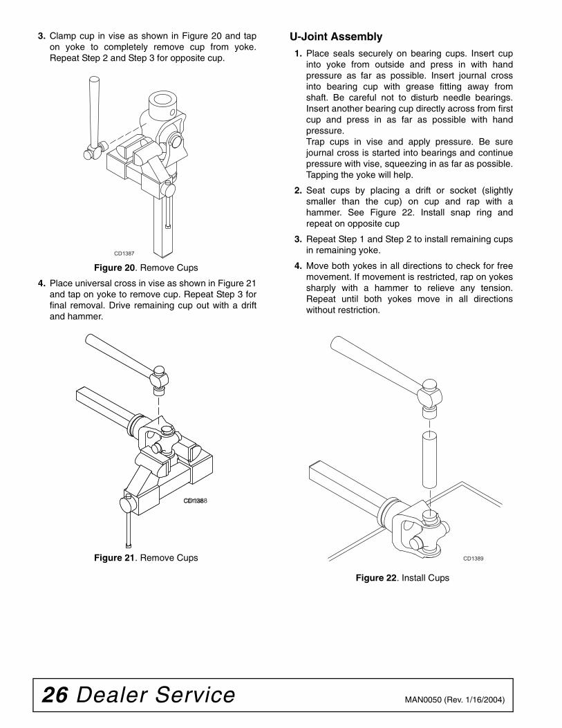
3. Clamp cup in vise as shown in Figure 20 and tapon yoke to completely remove cup from yoke.Repeat Step 2 and Step 3 for opposite cup.
Figure 20. Remove Cups
4. Place universal cross in vise as shown in Figure 21and tap on yoke to remove cup. Repeat Step 3 forfinal removal. Drive remaining cup out with a driftand hammer.
Figure 21. Remove Cups
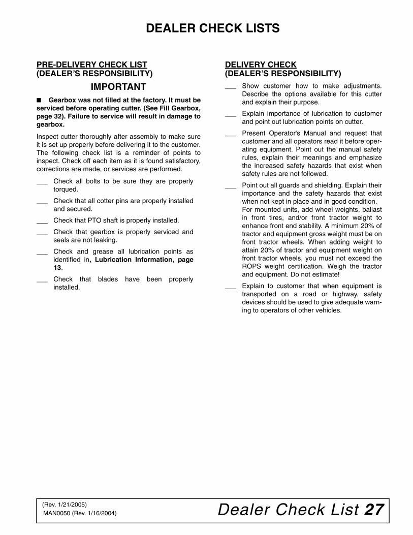
U-Joint Assembly1. Place seals securely on bearing cups. Insert cup
into yoke from outside and press in with handpressure as far as possible. Insert journal crossinto bearing cup with grease fitting away fromshaft. Be careful not to disturb needle bearings.Insert another bearing cup directly across from firstcup and press in as far as possible with handpressure.Trap cups in vise and apply pressure. Be surejournal cross is started into bearings and continuepressure with vise, squeezing in as far as possible.Tapping the yoke will help.
2. Seat cups by placing a drift or socket (slightlysmaller than the cup) on cup and rap with ahammer. See Figure 22. Install snap ring andrepeat on opposite cup
3. Repeat Step 1 and Step 2 to install remaining cupsin remaining yoke.
4. Move both yokes in all directions to check for freemovement. If movement is restricted, rap on yokessharply with a hammer to relieve any tension.Repeat until both yokes move in all directionswithout restriction.
Figure 22. Install Cups
CD1387
CD1388CD1388
CD1389
Dealer Check List 27MAN0050 (Rev. 1/16/2004)
DEALER CHECK LISTS
PRE-DELIVERY CHECK LIST(DEALER’S RESPONSIBILITY)
IMPORTANT■ Gearbox was not filled at the factory. It must beserviced before operating cutter. (See Fill Gearbox,page 32). Failure to service will result in damage togearbox.
Inspect cutter thoroughly after assembly to make sureit is set up properly before delivering it to the customer.The following check list is a reminder of points toinspect. Check off each item as it is found satisfactory,corrections are made, or services are performed.
___ Check all bolts to be sure they are properlytorqued.
___ Check that all cotter pins are properly installedand secured.
___ Check that PTO shaft is properly installed.
___ Check that gearbox is properly serviced andseals are not leaking.
___ Check and grease all lubrication points asidentified in, Lubrication Information, page13.
___ Check that blades have been properlyinstalled.
DELIVERY CHECK(DEALER’S RESPONSIBILITY)___ Show customer how to make adjustments.
Describe the options available for this cutterand explain their purpose.
___ Explain importance of lubrication to customerand point out lubrication points on cutter.
___ Present Operator's Manual and request thatcustomer and all operators read it before oper-ating equipment. Point out the manual safetyrules, explain their meanings and emphasizethe increased safety hazards that exist whensafety rules are not followed.
___ Point out all guards and shielding. Explain theirimportance and the safety hazards that existwhen not kept in place and in good condition.For mounted units, add wheel weights, ballastin front tires, and/or front tractor weight toenhance front end stability. A minimum 20% oftractor and equipment gross weight must be onfront tractor wheels. When adding weight toattain 20% of tractor and equipment weight onfront tractor wheels, you must not exceed theROPS weight certification. Weigh the tractorand equipment. Do not estimate!
___ Explain to customer that when equipment istransported on a road or highway, safetydevices should be used to give adequate warn-ing to operators of other vehicles.
(Rev. 1/21/2005)

28 Assembly MAN0050 (Rev. 1/16/2004)
ASSEMBLY
DEALER SET-UP INSTRUCTIONSAssembly of this cutter is the responsibility of theWoods dealer. It should be delivered to the owner com-pletely assembled, lubricated, and adjusted for normalcutting conditions.
The cutter is shipped partially assembled. Assemblywill be easier if aligned and loosely assembled beforetightening hardware. Recommended torque values forhardware are located in the Bolt Torque Chart, page46.
Complete Dealer Check Lists, page 27 when youhave completed the assembly.
Full chain, rubber, or steel band shielding,designed to reduce the possibility of thrownobjects, must be installed when operating in popu-lated areas or other areas where thrown objectscould injure people or damage property. If this
machine is not equipped with full chain, rubber, orsteel band shielding, operation must be stoppedwhen anyone comes within several hundred feet.
Make sure spring-activated locking pin or collarslides freely and is seated firmly in tractor PTOspline groove.
Operate tractor PTO at the rpm speed stated in“Specifications” section.
Always wear relatively tight and belted clothingto avoid getting caught in moving parts. Wearsturdy, rough-soled work shoes and protectiveequipment for eyes, hair, hands, hearing, and head;and respirator or filter mask where appropriate.
������
�������
CAUTION
Figure 23. BB48 & BB60 Shipping Configuration
1. Mounting pin hardware2. A-frame bar3. Upper mounting hardware
(under clutch shield)4. Diagonal brace
5A. Diagonal brace barmounting hole
5B. Tailwheel pivot hole6. Tailwheel bracket7. PTO Hanger9. Tailwheel
10. Height adjustment12. Bag of hardware13. Driveline (Shear bolt)14. Clutch shield
2
5A5B
6
7
9
10
1
DP4
4
13
314
(Rev. 12/2/2005)

Assembly 29MAN0050 (Rev. 1/16/2004)
ASSEMBLE CUTTER
Disassemble Shipping Unit1. Remove all parts that are wired and strapped to
cutter.
2. Remove cap screws (13) and flange lock nuts (14)that are securing A-frame bars (2) to the cuttingheight adjustment holes (10).
3. Remove cap screws (13) and flange lock nuts (14)that are securing tailwheel bracket (6) and diagonalbrace bars (4) to cutter. See Figure 25.
2. A-frame bar4. Diagonal brace bar6. Tailwheel bracket
10. Height adjustment13. 5/8 NC x 2 Cap screw14. 5/8 NC Flange lock nut
Figure 25. BB60 Shown
Figure 24. BB72 & BB84 Shipping Configuration
1
7
DP6A
5A
69
12
3
13
1. Mounting pin hardware2. A-frame bar3. Upper mounting hardware4. Diagonal brace
5A. Diagonal brace barmounting hole
5B. Tailwheel pivot hole6. Tailwheel bracket7. PTO Hanger9. Tailwheel
10. Height adjustment12. Bag of hardware13. Driveline (Slip clutch)14. Clutch shield
214
10
4
5B
13
13
14
14
6
1314
42
DP5A
10
(Rev. 1/21/2005)
30 Assembly MAN0050 (Rev. 1/16/2004)
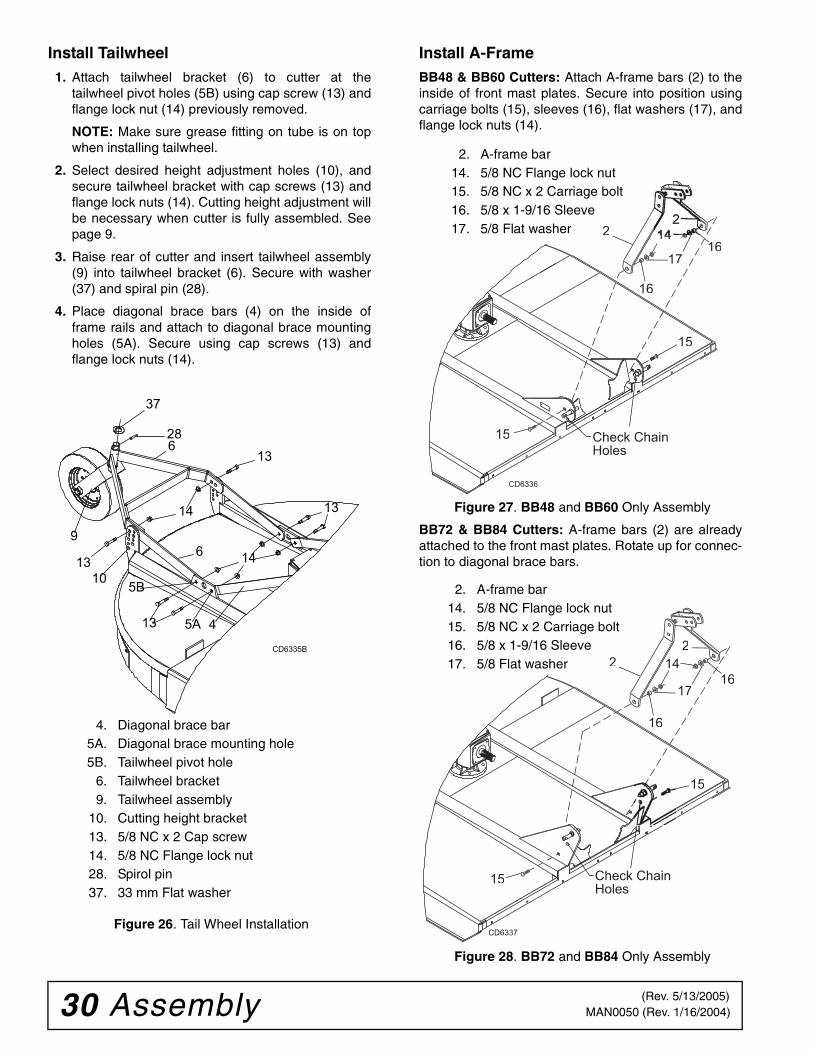
Install Tailwheel1. Attach tailwheel bracket (6) to cutter at the
tailwheel pivot holes (5B) using cap screw (13) andflange lock nut (14) previously removed.
NOTE: Make sure grease fitting on tube is on topwhen installing tailwheel.
2. Select desired height adjustment holes (10), andsecure tailwheel bracket with cap screws (13) andflange lock nuts (14). Cutting height adjustment willbe necessary when cutter is fully assembled. Seepage 9.
3. Raise rear of cutter and insert tailwheel assembly(9) into tailwheel bracket (6). Secure with washer(37) and spiral pin (28).
4. Place diagonal brace bars (4) on the inside offrame rails and attach to diagonal brace mountingholes (5A). Secure using cap screws (13) andflange lock nuts (14).
Figure 26. Tail Wheel Installation
Install A-FrameBB48 & BB60 Cutters: Attach A-frame bars (2) to theinside of front mast plates. Secure into position usingcarriage bolts (15), sleeves (16), flat washers (17), andflange lock nuts (14).
Figure 27. BB48 and BB60 Only Assembly
BB72 & BB84 Cutters: A-frame bars (2) are alreadyattached to the front mast plates. Rotate up for connec-tion to diagonal brace bars.
Figure 28. BB72 and BB84 Only Assembly
CD6335B
9
13
5B
13
14
14
13
10
13
5A 4
6
628
37
4. Diagonal brace bar5A. Diagonal brace mounting hole5B. Tailwheel pivot hole
6. Tailwheel bracket9. Tailwheel assembly
10. Cutting height bracket13. 5/8 NC x 2 Cap screw14. 5/8 NC Flange lock nut28. Spirol pin37. 33 mm Flat washer
15
15
17
2
161
16
CD6336
Check Chain Holes
2. A-frame bar14. 5/8 NC Flange lock nut15. 5/8 NC x 2 Carriage bolt16. 5/8 x 1-9/16 Sleeve17. 5/8 Flat washer
15
15
17
2
2
16
16
Check Chain Holes
CD6337
2. A-frame bar14. 5/8 NC Flange lock nut15. 5/8 NC x 2 Carriage bolt16. 5/8 x 1-9/16 Sleeve17. 5/8 Flat washer
(Rev. 5/13/2005)
Assembly 31MAN0050 (Rev. 1/16/2004)
Install A-Frame to Diagonal Brace Bars1. Remove cap screw (18) and flange lock nut (20)
from top hole on A-frame bars. Leave spacer (19)and float link (27) together.
2. Position diagonal brace bars (4) on the outside ofA-frame bars (3).
3. Align diagonal brace bars with top hole in A-framebars, float link, and spacer. Secure with cap screw(18) and flange lock nut (20) that were previouslyremoved.
Figure 29. Diagonal Brace Barsto A-Frame Connection
Quick Hitch Set-UpAn optional Quick Hitch attachment may be used onthis cutter. Install A-frame as shown below (Figure 30).
Figure 30. Diagonal Brace Barsto A-Frame Connection for Quick Hitch
INSTALL DRIVELINESelect either the standard shear bolt or optional slipclutch driveline.
Install Driveline Shear Bolt BB48 & BB60 Only
IMPORTANT■ A grade 2 bolt must be used for the shear boltto provide gearbox protection.
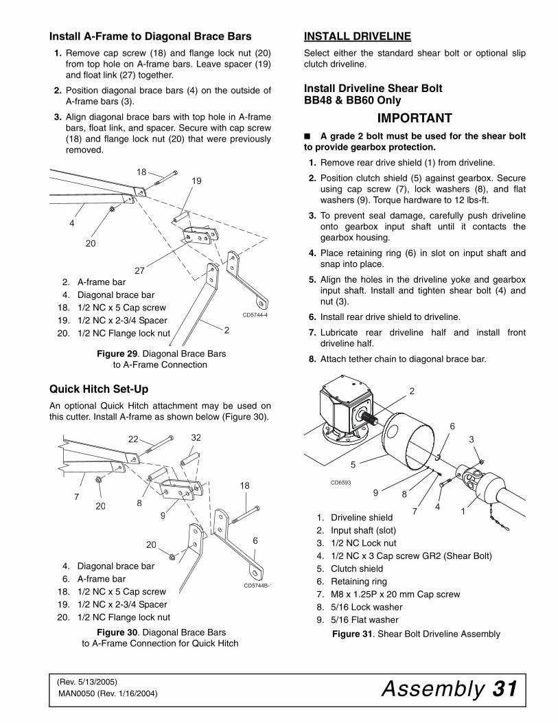
1. Remove rear drive shield (1) from driveline.
2. Position clutch shield (5) against gearbox. Secureusing cap screw (7), lock washers (8), and flatwashers (9). Torque hardware to 12 lbs-ft.
3. To prevent seal damage, carefully push drivelineonto gearbox input shaft until it contacts thegearbox housing.
4. Place retaining ring (6) in slot on input shaft andsnap into place.
5. Align the holes in the driveline yoke and gearboxinput shaft. Install and tighten shear bolt (4) andnut (3).
6. Install rear drive shield to driveline.
7. Lubricate rear driveline half and install frontdriveline half.
8. Attach tether chain to diagonal brace bar.
Figure 31. Shear Bolt Driveline Assembly
4
20
1819
27
2
CD5744-4
2. A-frame bar4. Diagonal brace bar
18. 1/2 NC x 5 Cap screw19. 1/2 NC x 2-3/4 Spacer20. 1/2 NC Flange lock nut
9
6
820
22
7
32
18
20
CD5744B-1
4. Diagonal brace bar6. A-frame bar
18. 1/2 NC x 5 Cap screw19. 1/2 NC x 2-3/4 Spacer20. 1/2 NC Flange lock nut
5
9 8
7
3
1
2
4
6
CD6593
1. Driveline shield2. Input shaft (slot)3. 1/2 NC Lock nut4. 1/2 NC x 3 Cap screw GR2 (Shear Bolt)5. Clutch shield6. Retaining ring7. M8 x 1.25P x 20 mm Cap screw8. 5/16 Lock washer9. 5/16 Flat washer
(Rev. 5/13/2005)
32 Assembly MAN0050 (Rev. 1/16/2004)
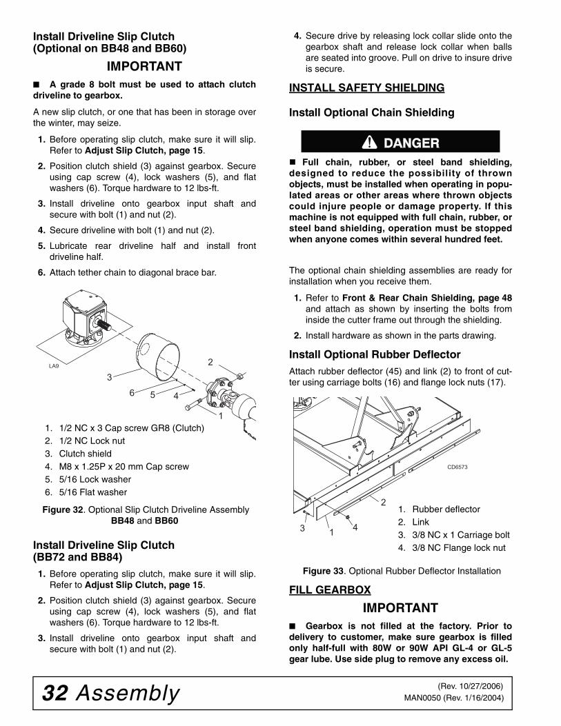
Install Driveline Slip Clutch (Optional on BB48 and BB60)
IMPORTANT■ A grade 8 bolt must be used to attach clutchdriveline to gearbox.
A new slip clutch, or one that has been in storage overthe winter, may seize.
1. Before operating slip clutch, make sure it will slip.Refer to Adjust Slip Clutch, page 15.
2. Position clutch shield (3) against gearbox. Secureusing cap screw (4), lock washers (5), and flatwashers (6). Torque hardware to 12 lbs-ft.
3. Install driveline onto gearbox input shaft andsecure with bolt (1) and nut (2).
4. Secure driveline with bolt (1) and nut (2).
5. Lubricate rear driveline half and install frontdriveline half.
6. Attach tether chain to diagonal brace bar.
Figure 32. Optional Slip Clutch Driveline Assembly BB48 and BB60
Install Driveline Slip Clutch (BB72 and BB84)1. Before operating slip clutch, make sure it will slip.
Refer to Adjust Slip Clutch, page 15.
2. Position clutch shield (3) against gearbox. Secureusing cap screw (4), lock washers (5), and flatwashers (6). Torque hardware to 12 lbs-ft.
3. Install driveline onto gearbox input shaft andsecure with bolt (1) and nut (2).
4. Secure drive by releasing lock collar slide onto thegearbox shaft and release lock collar when ballsare seated into groove. Pull on drive to insure driveis secure.
INSTALL SAFETY SHIELDING
Install Optional Chain Shielding
Full chain, rubber, or steel band shielding,designed to reduce the possibility of thrownobjects, must be installed when operating in popu-lated areas or other areas where thrown objectscould injure people or damage property. If thismachine is not equipped with full chain, rubber, orsteel band shielding, operation must be stoppedwhen anyone comes within several hundred feet.
The optional chain shielding assemblies are ready forinstallation when you receive them.
1. Refer to Front & Rear Chain Shielding, page 48and attach as shown by inserting the bolts frominside the cutter frame out through the shielding.
2. Install hardware as shown in the parts drawing.
Install Optional Rubber DeflectorAttach rubber deflector (45) and link (2) to front of cut-ter using carriage bolts (16) and flange lock nuts (17).
Figure 33. Optional Rubber Deflector Installation
FILL GEARBOX
IMPORTANT■ Gearbox is not filled at the factory. Prior todelivery to customer, make sure gearbox is filledonly half-full with 80W or 90W API GL-4 or GL-5gear lube. Use side plug to remove any excess oil.
1
3
2
56
LA9
4
1. 1/2 NC x 3 Cap screw GR8 (Clutch)2. 1/2 NC Lock nut3. Clutch shield4. M8 x 1.25P x 20 mm Cap screw5. 5/16 Lock washer6. 5/16 Flat washer
������
CD6573
1
2
3 4
1. Rubber deflector2. Link3. 3/8 NC x 1 Carriage bolt4. 3/8 NC Flange lock nut
(Rev. 10/27/2006)
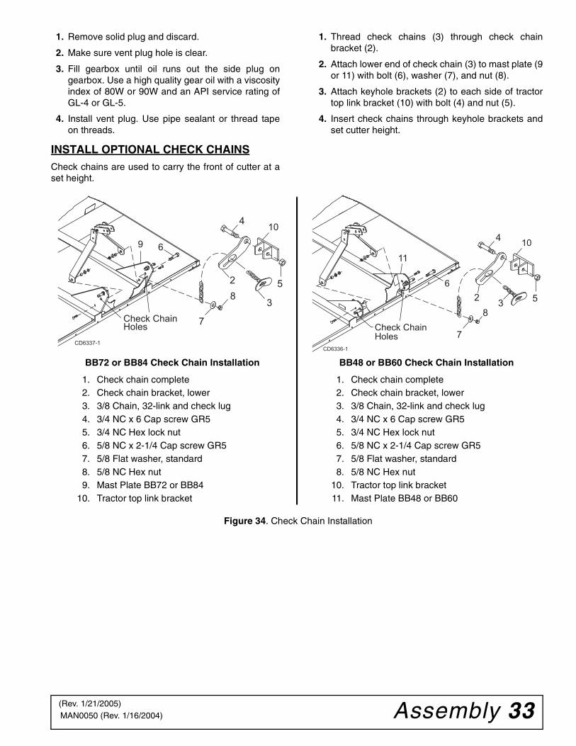
Assembly 33MAN0050 (Rev. 1/16/2004)
1. Remove solid plug and discard.
2. Make sure vent plug hole is clear.
3. Fill gearbox until oil runs out the side plug ongearbox. Use a high quality gear oil with a viscosityindex of 80W or 90W and an API service rating ofGL-4 or GL-5.
4. Install vent plug. Use pipe sealant or thread tapeon threads.
INSTALL OPTIONAL CHECK CHAINSCheck chains are used to carry the front of cutter at aset height.
1. Thread check chains (3) through check chainbracket (2).
2. Attach lower end of check chain (3) to mast plate (9or 11) with bolt (6), washer (7), and nut (8).
3. Attach keyhole brackets (2) to each side of tractortop link bracket (10) with bolt (4) and nut (5).
4. Insert check chains through keyhole brackets andset cutter height.
Figure 34. Check Chain Installation
9
Check Chain Holes
CD6337-1
2
3
4
5
7
8
6
10
6
CD6336-1
Check Chain Holes
10
11
23
4
5
7
8
BB72 or BB84 Check Chain Installation
1. Check chain complete2. Check chain bracket, lower3. 3/8 Chain, 32-link and check lug4. 3/4 NC x 6 Cap screw GR55. 3/4 NC Hex lock nut6. 5/8 NC x 2-1/4 Cap screw GR57. 5/8 Flat washer, standard8. 5/8 NC Hex nut9. Mast Plate BB72 or BB84
10. Tractor top link bracket
BB48 or BB60 Check Chain Installation
1. Check chain complete2. Check chain bracket, lower3. 3/8 Chain, 32-link and check lug4. 3/4 NC x 6 Cap screw GR55. 3/4 NC Hex lock nut6. 5/8 NC x 2-1/4 Cap screw GR57. 5/8 Flat washer, standard8. 5/8 NC Hex nut
10. Tractor top link bracket11. Mast Plate BB48 or BB60
(Rev. 1/21/2005)

34 Assembly MAN0050 (Rev. 1/16/2004)
NOTE
(Rev. 1/21/2005)
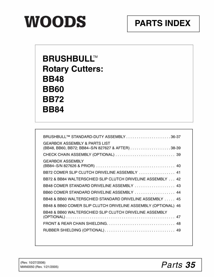
Parts 35MAN0050 (Rev. 1/21/2005)
BRUSHBULL™ STANDARD-DUTY ASSEMBLY . . . . . . . . . . . . . . . . . . . . . 36-37
GEARBOX ASSEMBLY & PARTS LIST(BB48, BB60, BB72; BB84–S/N 827627 & AFTER) . . . . . . . . . . . . . . . . . . . 38-39
CHECK CHAIN ASSEMBLY (OPTIONAL) . . . . . . . . . . . . . . . . . . . . . . . . . . . . 39
GEARBOX ASSEMBLY(BB84–S/N 827626 & PRIOR) . . . . . . . . . . . . . . . . . . . . . . . . . . . . . . . . . . . . . 40
BB72 COMER SLIP CLUTCH DRIVELINE ASSEMBLY . . . . . . . . . . . . . . . . . 41
BB72 & BB84 WALTERSCHIED SLIP CLUTCH DRIVELINE ASSEMBLY . . . 42
BB48 COMER STANDARD DRIVELINE ASSEMBLY . . . . . . . . . . . . . . . . . . . 43
BB60 COMER STANDARD DRIVELINE ASSEMBLY . . . . . . . . . . . . . . . . . . . 44
BB48 & BB60 WALTERSCHIED STANDARD DRIVELINE ASSEMBLY . . . . . 45
BB48 & BB60 COMER SLIP CLUTCH DRIVELINE ASSEMBLY (OPTIONAL) 46
BB48 & BB60 WALTERSCHIED SLIP CLUTCH DRIVELINE ASSEMBLY (OPTIONAL) . . . . . . . . . . . . . . . . . . . . . . . . . . . . . . . . . . . . . . . . . . . . . . . . . . . 47
FRONT & REAR CHAIN SHIELDING. . . . . . . . . . . . . . . . . . . . . . . . . . . . . . . . 48
RUBBER SHIELDING (OPTIONAL) . . . . . . . . . . . . . . . . . . . . . . . . . . . . . . . . . 49
PARTS INDEX
BRUSHBULLRotary Cutters:BB48BB60BB72BB84
TM
(Rev. 10/27/2006)

36 Parts MAN0050 (Rev. 1/21/2005)
BRUSHBULL STANDARD DUTY ASSEMBLYBB48, BB60, BB72 & BB84 (BB84 SHOWN)
14A
14
QU
ICK
HIT
CH
CO
NFI
GU
RAT
ION
& H
AR
DW
AR
E
34
50
127
35
36
35
10A
41
3713
38
40
12,5
515
39
14B
1114
C
10B
9
8
7
46
23
23
53
53
47
3
1
66
2526
27
28
29
12
21
21
21
21
24
24
20
18
12
19
19
9
47
6
1219
198
20
22
7
732
18
20
1233 21
57
49
51
4856
555430
31
42
43
43
44
5
CD
5744
F
Units with Serial Number 994126 & prior include tail wheel with fabri-cated steel hub. Units with Serial Number 994127 & after include tail wheel with cast iron hub. Item 14 ( 4 x 15 Notat Tire/Wheel) includes cast iron hub.
(Rev. 10/27/2006)

Parts 37MAN0050 (Rev. 1/21/2005)
BB48, BB60, BB72 & BB84 PARTS LIST
REF PART QTY DESCRIPTION
3 57236 1 Rear band - BB483 57210 1 Rear band - BB603 57183 1 Rear band - BB723 57184 1 Rear band - BB845 57162 1 Tailwheel assembly6 57238 2 Link, offset - (A-frame bar) BB48 & 606 57223 2 Link, offset - (A-frame bar) BB72 & 847 57239 2 Link, offset - (Diagonal brace) BB487 57220 2 Link, offset - (Diagonal brace) BB607 57153 2 Link, offset - (Diagonal brace) BB727 57199 2 Link, offset - (Diagonal brace) BB848 64814 1 Spacer 1/2 x 2-3/49 15321 1 Link, bent .38 x 2.5 x 9.1310 57182 1 Sleeve, .656 x .997 x 5.39
10B 1013219 1 Sleeve, .656 x .985 x 5.24 (S/N 994126 & prior / cast iron hub)
11 23638 1 5/8 NC x 7 Cap screw GR511 1013878 1 M24 x 2 x 192 Spindle bolt (S/N 994127
& after)12 19025 13 5/8 NC Flange lock nut13 13853 1 Spirol pin 3/8 x 1-3/413 40775 1 Spirol pin 10 mm x 65 mm (S/N 994127
& after)14 15373 1 4 x 16 Solid core tire - BB4814 1013222 1 4 x 15 Notat tire / wheel (S/N 994126 &
prior)(includes 10B)14A 1009091 1 Wheel hub assembly (Notat tire only)14B 1009090 2 Bushing Flange 1.00 x 1.37 x 1.00
(Notat tire only)14B 1013880 2 Bushing, flanged .984 x 1.378 x .98 (For
cast iron hub only)14C 1013879 1 Cast iron wheel hub (S/N 994127 &
after)15 15314 1 Tail wheel clevis15 1013220 1 Tail wheel clevis (S/N 994127 & after)16 6697 *8 3/8 NC x 1 Carriage bolt GR517 14350 8 3/8 NC Flange lock nut18 23479 *1 1/2 NC x 5 Cap screw GR519 1791 2 Sleeve 5/8 x 1 x 9/16 HT20 11900 2 1/2 Flange lock nut21 902 *10 5/8 x 2 Cap screw GR522 10380 *1 1/2 NC x 4 Cap screw GR5 (used for
quick hitch only)23 2855 *2 5/8 x 2 Carriage bolt GR524 33661 2 Cat. 1 Mounting pin (with nut &
lock washer; does not include 53) (BB48, BB60, BB72)
24 30006 2 Cat. 2 Mounting pin (with nut & lock washer; Does not include 53) (BB84)
25 24801 4 M8 x 1.25P x 20 mm Cap screw26 35155 *4 5/16 Flat washer27 2472 *4 5/16 Lock washer28 1002048 1 Clutch shield, 100 & 143 mm BC29 57403 1 Complete drive asy - BB72 (page 42)29 1020901 1 Complete drive asy - BB72
30 57409 1 Complete drive asy - BB84 30 40554 1 Complete drive asy - BB4830 40555 1 Complete drive asy - BB6030 1009509 1 Complete drive asy - BB4830 1009510 1 Complete drive asy - BB6031 ——— 1 BB48 & BB60 Standard drive or BB48
& BB60 Slip clutch drive 32 33657 1 1/2 x 3/4 x 2-13/16 Sleeve
(used for quick hitch only)33 57817 4 5/8 Flat washer, hardened (BB48,
BB60, BB72)33 57798 4 3/4 Flat washer, hardened BB8434 1003828 1 Manual tube 35 24409 *2 5/16 NC x 1 Carriage bolt36 4529 *2 5/16 NC Hex nut37 * 1 Washer, 33 mm x 56 mm x 4 mm (S/N
994127 & after)38 * 1 Cotter pin (S/N 994127 & after)39 23029 4 M12-1.75P x 25 Cap screw (S/N
994127 & after)40 * 4 M12 Flat washer (S/N 994127 & after41 4676 1 4 x 15 Notat tire & rim (S/N 994127 &
after)42 15349 1 1/2 NC x 3 Shear bolt GR243 765 *2 1/2 NC Lock nut - BB48 & BB6044 1024632 1 1/2 NC x 3 Cap screw GR8 - Clutch46 57076 1 Vent plug, (See page 38)47 692 *2 5/8 Flat washer48 15331 2 Blade pin - BB48 & BB60
(includes washer & nut)48 57093 2 Blade pin - BB72 & BB84
(includes washer & nut)49 30310KT 1 Blade 3/8 x 3 x 16 CCW - BB4849 15326KT 1 Blade 3/8 x 3 x 20.50 CCW - BB6049 57189KT 1 Blade 1/2 x 3 x 26.5 CCW
BB72 & BB8450 1013200 1 Crossbar and hub - BB48, BB60, BB7250 57190 1 Crossbar asy
(BB84 - S/N 827626 & prior)50 1004127 1 Crossbar asy
(BB84–S/N 827627 & after)51 15330 1 Stump jumber - (BB48, BB60, BB72)53 1001521 2 Washer, .880 x 1.88 x .5054 20893 1 Washer, 25 x 44 x 4 mm (BB48, BB60,
BB72)54 39322 1 Washer, 31 x 56 x 4 mm BB8455 20892 2 Castle nut metric, M24 x 2 (BB48,
BB60, BB72)(S/N 994127 & after)55 39323 1 Castle nut metric M30 x 2 BB8456 *1 6" Wire, 9 gauge 57 15345 1 Retaining ring, .05 x 1.38NS 15358 1 Safety decal setNS 1000624 1 Complete decal set
* Standard hardware, obtain locallyNS Not Shown
REF PART QTY DESCRIPTION
(Rev. 10/27/2006)
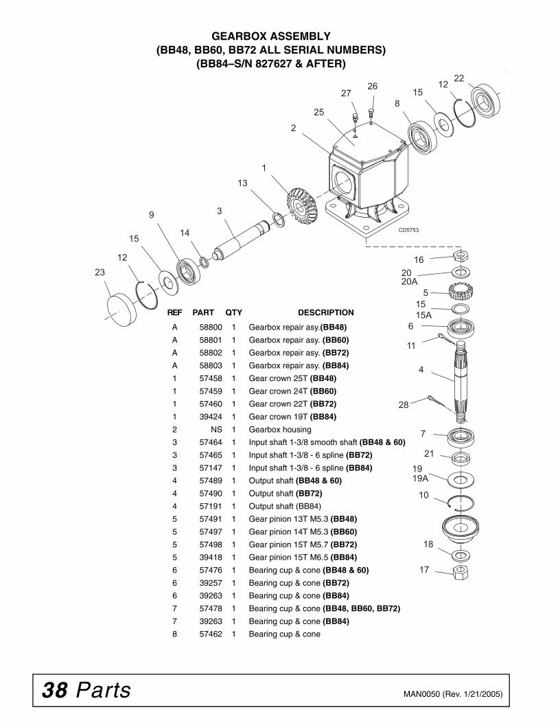
38 Parts MAN0050 (Rev. 1/21/2005)
GEARBOX ASSEMBLY (BB48, BB60, BB72 ALL SERIAL NUMBERS)
(BB84–S/N 827627 & AFTER)
1512
22
113
3
14
9
1223
1620
51515A
6
11
4
7
21
19
10
18
17
258
27
15
2
26
CD5753
28
20A
19A
REF PART QTY DESCRIPTION
A 58800 1 Gearbox repair asy.(BB48)
A 58801 1 Gearbox repair asy. (BB60)
A 58802 1 Gearbox repair asy. (BB72)
A 58803 1 Gearbox repair asy. (BB84)
1 57458 1 Gear crown 25T (BB48)
1 57459 1 Gear crown 24T (BB60)
1 57460 1 Gear crown 22T (BB72)
1 39424 1 Gear crown 19T (BB84)
2 NS 1 Gearbox housing
3 57464 1 Input shaft 1-3/8 smooth shaft (BB48 & 60)
3 57465 1 Input shaft 1-3/8 - 6 spline (BB72)
3 57147 1 Input shaft 1-3/8 - 6 spline (BB84)
4 57489 1 Output shaft (BB48 & 60)
4 57490 1 Output shaft (BB72)
4 57191 1 Output shaft (BB84)
5 57491 1 Gear pinion 13T M5.3 (BB48)
5 57497 1 Gear pinion 14T M5.3 (BB60)
5 57498 1 Gear pinion 15T M5.7 (BB72)
5 39418 1 Gear pinion 15T M6.5 (BB84)
6 57476 1 Bearing cup & cone (BB48 & 60)
6 39257 1 Bearing cup & cone (BB72)
6 39263 1 Bearing cup & cone (BB84)
7 57478 1 Bearing cup & cone (BB48, BB60, BB72)
7 39263 1 Bearing cup & cone (BB84)
8 57462 1 Bearing cup & cone
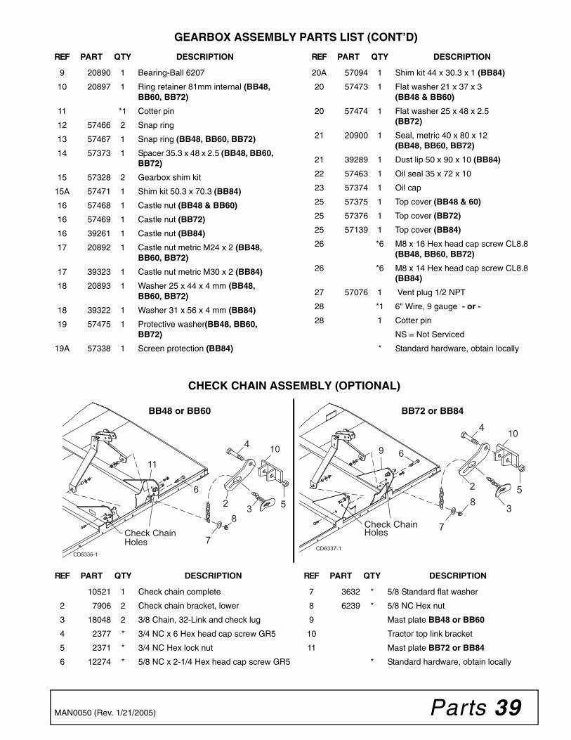
Parts 39MAN0050 (Rev. 1/21/2005)
GEARBOX ASSEMBLY PARTS LIST (CONT’D)
CHECK CHAIN ASSEMBLY (OPTIONAL)
REF PART QTY DESCRIPTION
9 20890 1 Bearing-Ball 6207
10 20897 1 Ring retainer 81mm internal (BB48, BB60, BB72)
11 *1 Cotter pin
12 57466 2 Snap ring
13 57467 1 Snap ring (BB48, BB60, BB72)
14 57373 1 Spacer 35.3 x 48 x 2.5 (BB48, BB60, BB72)
15 57328 2 Gearbox shim kit
15A 57471 1 Shim kit 50.3 x 70.3 (BB84)
16 57468 1 Castle nut (BB48 & BB60)
16 57469 1 Castle nut (BB72)
16 39261 1 Castle nut (BB84)
17 20892 1 Castle nut metric M24 x 2 (BB48, BB60, BB72)
17 39323 1 Castle nut metric M30 x 2 (BB84)
18 20893 1 Washer 25 x 44 x 4 mm (BB48, BB60, BB72)
18 39322 1 Washer 31 x 56 x 4 mm (BB84)
19 57475 1 Protective washer(BB48, BB60, BB72)
19A 57338 1 Screen protection (BB84)
REF PART QTY DESCRIPTION
20A 57094 1 Shim kit 44 x 30.3 x 1 (BB84)
20 57473 1 Flat washer 21 x 37 x 3(BB48 & BB60)
20 57474 1 Flat washer 25 x 48 x 2.5(BB72)
21 20900 1 Seal, metric 40 x 80 x 12(BB48, BB60, BB72)
21 39289 1 Dust lip 50 x 90 x 10 (BB84)
22 57463 1 Oil seal 35 x 72 x 10
23 57374 1 Oil cap
25 57375 1 Top cover (BB48 & 60)
25 57376 1 Top cover (BB72)
25 57139 1 Top cover (BB84)
26 *6 M8 x 16 Hex head cap screw CL8.8 (BB48, BB60, BB72)
26 *6 M8 x 14 Hex head cap screw CL8.8 (BB84)
27 57076 1 Vent plug 1/2 NPT
28 *1 6" Wire, 9 gauge - or -
28 1 Cotter pin
NS = Not Serviced
* Standard hardware, obtain locally
6
CD6336-1
Check Chain Holes
10
11
23
4
5
7
8
9
Check Chain Holes
CD6337-1
2
3
4
5
7
8
6
10
REF PART QTY DESCRIPTION
10521 1 Check chain complete
2 7906 2 Check chain bracket, lower
3 18048 2 3/8 Chain, 32-Link and check lug
4 2377 * 3/4 NC x 6 Hex head cap screw GR5
5 2371 * 3/4 NC Hex lock nut
6 12274 * 5/8 NC x 2-1/4 Hex head cap screw GR5
REF PART QTY DESCRIPTION
7 3632 * 5/8 Standard flat washer
8 6239 * 5/8 NC Hex nut
9 Mast plate BB48 or BB60
10 Tractor top link bracket
11 Mast plate BB72 or BB84
* Standard hardware, obtain locally
BB72 or BB84BB48 or BB60

40 Parts MAN0050 (Rev. 1/21/2005)
GEARBOX ASSEMBLY (BB84–S/N 827626 & PRIOR)
27 - Shim Kit
CD4332
REF PART QTY DESCRIPTION
A 39124 1 Gearbox repair asy
1 39421 1 Lower cover
2 39323 1 Gasket
3 39420 1 Seal
4 39416 1 Shaft
5 39263 2 Bearing
6 39417 1 Spacer
7 ——— A/R Shim, 45.3 mm ID x 65.3 mm OD
8 39418 1 Pinion gear, 15-tooth
9 ——— Gearbox housing (not sold separately)
10 39414 1 Bearing
11 39415 1 Shaft
12 39424 1 Gear, 19-tooth
13 39425 1 Bearing
14 39427 1 Seal
15 39426 1 Gasket
16 39428 1 Front cover
17 39422 4 10 mm Lock washer
18 64291 1 5/32 x 1 Cotter pin
19 65294 1 3/8 NPT Square head pipe plug
20 39325 1 3/8 NPT Vented plug
REF PART QTY DESCRIPTION
21 24801 8 8 mm x 1.25P x 20 mm Hex head cap screw
22 24802 4 10 mm x 1.25P x 25 mm Hex head cap screw
23 2472 8 5/16 Standard lock washer
24 39261 1 30 mm x 1.50 Hex castle nut
25 ——— A/R Shim, 40.3 mm ID x 51.5 mm OD
26 ——— A/R Shim, 35.3 mm ID x 43.0 mm OD
27 39413 A/R Shim kit (includes items 7, 25, 26)
A/R = As Required

Parts 41MAN0050 (Rev. 1/21/2005)
BB72 COMER SLIP CLUTCH DRIVELINE ASSEMBLY
CD6937
22
21
1920
23
6
9
1
3 4
2
5
2
14
NOTE: EXAMINE THE DRIVELINE PROFILE TO DETERMINE THE CORRECT REPAIR PARTS FOR THE UNIT
WALTERSCHIED PROFILE
PG 42
11 131210
14 16 171518
COMER PROFILE
PG 41
REF PART QTY DESCRIPTION
- 1020901 1 Complete 540 driveline asy
1 1001300 2 Complete collar yoke C12 1-3/8 - 6
2 38478 2 Cross and bearing kit
3 1019442 1 Outer cone fix ring
4 30922 6 Protection fixing screw
5 1019444 1 Inner cone fix ring
6 30917 2 Chain-shield tether
9 1001340 1 Lock collar repair kit
10 1019449 1 Friction clutch
11 1001311 8 Spring
12 1001312 1 Flanged yoke
13 1001313 1 Bushing
14 1001314 2 Lining ring
15 1001316 1 Flanged hub F12
16 1001317 1 Pressure plate
17 1001318 8 Bolt & nut M10 x 80
18 1001315 1 Bolt & nut M12 x 1.25 x 65
19 1001302 1 Flexible pin
20 1001301 1 Outer yoke tube
21 1001305 1 Flexible pin
22 1001306 1 Inner tube yoke
23 1021552 1 Shield, complete
REF PART QTY DESCRIPTION
(Rev. 10/27/2006)
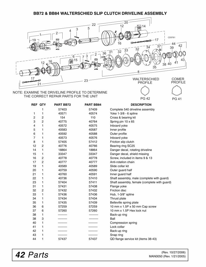
42 Parts MAN0050 (Rev. 1/21/2005)
BB72 & BB84 WALTERSCHIED SLIP CLUTCH DRIVELINE ASSEMBLY
2220
2321
16
1619
12 14
12
17
15
17
42
414038
39
43
4437
35
3633
34323231
214 3 5
8
2376
CD5761
NOTE: EXAMINE THE DRIVELINE PROFILE TO DETERMINE THE CORRECT REPAIR PARTS FOR THE UNIT
WALTERSCHIED PROFILE
PG 42
COMER PROFILE
PG 41
REF QTY PART BB72 PART BB84 DESCRIPTION
1 57403 57409 Complete 540 driveline assembly1 1 40571 40574 Yoke 1-3/8 - 6 spline2 2 154 110 Cross & bearing kit3 2 40775 40764 Spring pin 10 x 654 1 40572 40575 Inboard yoke5 1 40583 40587 Inner profile6 1 40592 40588 Outer profile7 1 40573 40576 Inboard yoke8 1 57405 57412 Friction slip clutch
12 2 40776 40766 Bearing ring SC2514 1 18864 18864 Danger decal, rotating driveline15 1 33347 33347 Danger decal, shield missing16 2 40778 40778 Screw, included in items 9 & 1317 2 40777 40777 Anti-rotation chain19 1 40589 40589 Slide collar kit20 1 40759 40590 Outer guard half21 1 40760 40591 Inner guard half22 1 40736 57410 Shaft assembly, male (complete with guard)23 1 57404 57411 Shaft assembly, female (complete with guard)31 1 57431 57438 Flange yoke32 2 57432 57432 Friction disc33 1 57436 57436 Hub, 1-3/8" spline34 1 57434 57434 Thrust plate35 1 57435 57439 Belleville spring plate36 6 57259 57259 10 mm x 1.5P x 50 mm Cap screw37 6 57260 57260 10 mm x 1.5P Hex lock nut38 1 ——— ——— Back-up ring38 3 ——— ——— Ball40 1 ——— ——— Compression spring41 1 ——— ——— Lock collar42 1 ——— ——— Back-up ring43 1 ——— ——— Snap ring44 1 57437 57437 QD flange service kit (items 38-43)
(Rev. 10/27/2006)
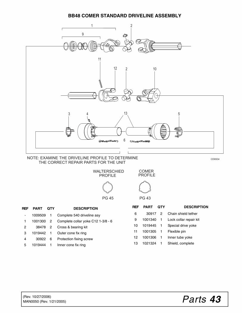
Parts 43MAN0050 (Rev. 1/21/2005)
BB48 COMER STANDARD DRIVELINE ASSEMBLY
6
CD6934
11
9
1
3 4
12
13
2
5
2 10
NOTE: EXAMINE THE DRIVELINE PROFILE TO DETERMINE THE CORRECT REPAIR PARTS FOR THE UNIT
WALTERSCHIED PROFILE
PG 45
COMER PROFILE
PG 43
REF PART QTY DESCRIPTION
- 1009509 1 Complete 540 driveline asy
1 1001300 2 Complete collar yoke C12 1-3/8 - 6
2 38478 2 Cross & bearing kit
3 1019442 1 Outer cone fix ring
4 30922 6 Protection fixing screw
5 1019444 1 Inner cone fix ring
6 30917 2 Chain shield tether
9 1001340 1 Lock collar repair kit
10 1019445 1 Special drive yoke
11 1001305 1 Flexible pin
12 1001306 1 Inner tube yoke
13 1021324 1 Shield, complete
REF PART QTY DESCRIPTION
(Rev. 10/27/2006)

44 Parts MAN0050 (Rev. 1/21/2005)
BB60 COMER STANDARD DRIVELINE ASSEMBLY
6
CD6935
9
1
3 4
2
5
2 1014
13
12 11
15
NOTE: EXAMINE THE DRIVELINE PROFILE TO DETERMINE THE CORRECT REPAIR PARTS FOR THE UNIT
WALTERSCHIED PROFILE
PG 45
COMER PROFILE
PG 44
REF PART QTY DESCRIPTION
- 1009510 1 Complete 540 drivline
1 1001300 2 Complete collar yoke C12 1-3/8 - 6
2 38478 2 Cross & bearing kit
3 1019442 1 Outer cone fix ring
4 30922 6 Protection fixing screw
5 1019444 1 Inner cone fix ring
6 30917 2 Chain shielding tether
9 1001340 1 Lock collar repair kit
10 1019445 1 Special drive yoke
11 1001302 1 Flexible pin
12 1001301 1 Outer yoke tube
13 1001305 1 Flexible pin
14 1001306 1 Inner tube yoke
15 1021550 1 Shield, complete
REF PART QTY DESCRIPTION
(Rev. 10/27/2006)

Parts 45MAN0050 (Rev. 1/21/2005)
BB48 & BB60 WALTERSCHEID STANDARD DRIVELINE ASSEMBLY
24
2321
121453
421
20 12 14
22
17
67
3 2 8 18
19 CD5578
WALTERSCHIED PROFILE
PG 45
COMER PROFILE
PG 43 & 44
NOTE: EXAMINE THE DRIVELINE PROFILE TO DETERMINE THE CORRECT REPAIR PARTS FOR THE UNIT
REF PART QTY DESCRIPTION
40554 1 Complete 540 driveline assembly (shear bolt) BB48 only
40555 1 Complete 540 driveline assembly(shear bolt) BB60 only
1 40571 1 Yoke, 1-3/8 - 6 SP (complete with lock collar)
2 154 2 Cross and bearing kit
3 40775 2 Spring pin 10 mm x 65 mm(pkg. of 10)
4 40572 1 Inboard yoke (male drive tube)
5 40583 1 Inner profile (cut to length)
6 40592 1 Outer profile (cut to length)
7 40573 1 Inboard yoke (female drive tube)
8 40580 1 Yoke, shear bolt
12 40776 2 Bearing ring (pkg. of 2)
14 40778 2 Screw (pkg. of 2)
REF PART QTY DESCRIPTION
17 40777 2 Anti-rotation chain
18 765 1 1/2 NC Lock nut
19 15349 1 1/2 NC x 3 Shear bolt
20 40589 2 Lock collar repair kit (without yoke)
21 40759 1 Guard, outer half, includes items 12, 13, and 14 (cut to length)
22 40761 1 Guard, inner half includes items 12, 13, and 17
23 40739 1 BB48 Shaft assembly, male half (complete with guard)
23 40733 1 BB60 Shaft assembly, male half (complete with guard)
24 40740 1 BB48 Shaft assembly, female half, (complete with guard and shear bolt yoke)
24 40734 1 BB60 Shaft assembly, female half, (complete with guard and shear bolt yoke)
(Rev. 10/27/2006)

46 Parts MAN0050 (Rev. 1/21/2005)
BB48 & BB60 COMER SLIP CLUTCH DRIVELINE ASSEMBLY (OPTIONAL)
6
9
1
3 4
2
5
21411 1312
1014 15 16 17
21
20
1819
22
CD6936NOTE: EXAMINE THE DRIVELINE PROFILE TO DETERMINE THE CORRECT REPAIR PARTS FOR THE UNIT
WALTERSCHIED PROFILE
PG 47
COMER PROFILE
PG 46
REF PART QTY DESCRIPTION
- 1020900 1 Complete 540 driveline assembly
1 1001300 2 Complete collar yoke C12 1-3/8 - 6
2 38478 2 Cross & bearing kit
3 1019442 1 Outer cone fix ring
4 30922 6 Protection fixing ring
5 1019444 1 Inner come fix ring
6 30917 2 Chain shield tether
9 1001340 1 Lock collar repair kit
10 1019446 1 Special friction clutch
11 1001311 8 Spring
12 1019447 1 Flanged yoke
13 1001313 1 Bushing
14 1001314 2 Lining ring
15 1019448 1 Special hub F10
16 1001317 1 Pressure plate
17 1001318 8 Bolt & nut M10 x 80
18 1001302 1 Flexible pin
19 1001301 1 Outer yoke tube
20 1001305 1 Flexible pin
21 1001306 1 Inner tube yoke
22 1021551 1 Shield, complete
REF PART QTY DESCRIPTION
(Rev. 10/27/2006)
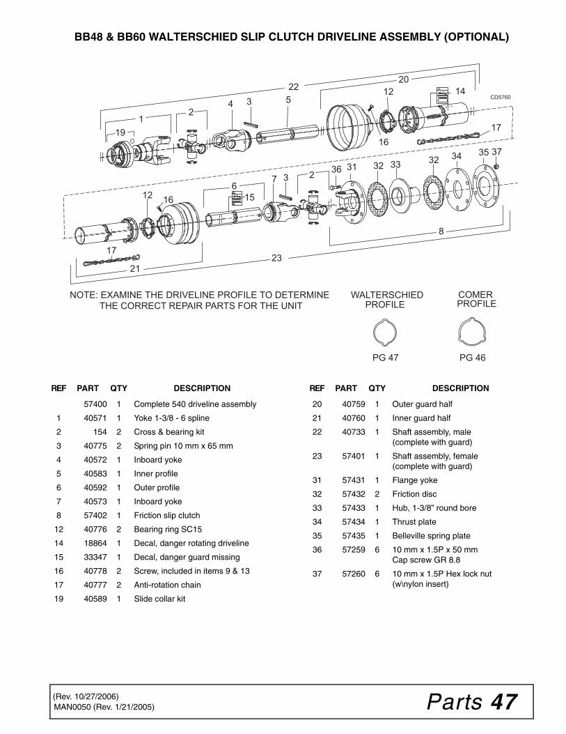
Parts 47MAN0050 (Rev. 1/21/2005)
BB48 & BB60 WALTERSCHIED SLIP CLUTCH DRIVELINE ASSEMBLY (OPTIONAL)
1619
1
34 512 14
12
17
637
15
2
17
2
2220
2321
8
37
36 3334 35
323231
16
CD5760
NOTE: EXAMINE THE DRIVELINE PROFILE TO DETERMINE THE CORRECT REPAIR PARTS FOR THE UNIT
WALTERSCHIED PROFILE
PG 47
COMER PROFILE
PG 46
REF PART QTY DESCRIPTION
57400 1 Complete 540 driveline assembly
1 40571 1 Yoke 1-3/8 - 6 spline
2 154 2 Cross & bearing kit
3 40775 2 Spring pin 10 mm x 65 mm
4 40572 1 Inboard yoke
5 40583 1 Inner profile
6 40592 1 Outer profile
7 40573 1 Inboard yoke
8 57402 1 Friction slip clutch
12 40776 2 Bearing ring SC15
14 18864 1 Decal, danger rotating driveline
15 33347 1 Decal, danger guard missing
16 40778 2 Screw, included in items 9 & 13
17 40777 2 Anti-rotation chain
19 40589 1 Slide collar kit
REF PART QTY DESCRIPTION
20 40759 1 Outer guard half
21 40760 1 Inner guard half
22 40733 1 Shaft assembly, male(complete with guard)
23 57401 1 Shaft assembly, female(complete with guard)
31 57431 1 Flange yoke
32 57432 2 Friction disc
33 57433 1 Hub, 1-3/8” round bore
34 57434 1 Thrust plate
35 57435 1 Belleville spring plate
36 57259 6 10 mm x 1.5P x 50 mmCap screw GR 8.8
37 57260 6 10 mm x 1.5P Hex lock nut(w\nylon insert)
(Rev. 10/27/2006)

48 Parts MAN0050 (Rev. 1/21/2005)
FRONT & REAR CHAIN SHIELDING (OPTIONAL)
2
1
4
3
7
6
9
8
CD5752A
10
11
REF QTYPARTBB48
PARTBB60
PARTBB72
PARTBB84
DESCRIPTION
1 1 57246 57143 57090 57128 Right front chain plate
2 1 57254 57144 57091 57127 Left front chain plate
3 2 1003643 1003645 1007850 1007851 .243 Dia. bent pin (front)
4 AR 5496 5496 5496 5496 5/16 - 7 Link chain (front)
6 1 57248 57142 57088 57125 Right rear chain plate
7 1 57247 57141 57089 57149 Left rear chain plate
8 2 57249 57138 57085 57146 .243 Dia. rolled bent pin (rear)
9 AR 4069 4069 4069 4069 5/16 - 4 Link chain (rear)
10 16 6697* 6697* 6697* 6697* 3/8 NC x 1 Carriage bolt
11 16 14350 14350 14350 14350 3/8 NC Flange hex nut
AR = As Required
* Standard hardware, obtain locally
(Rev. 10/27/2006)
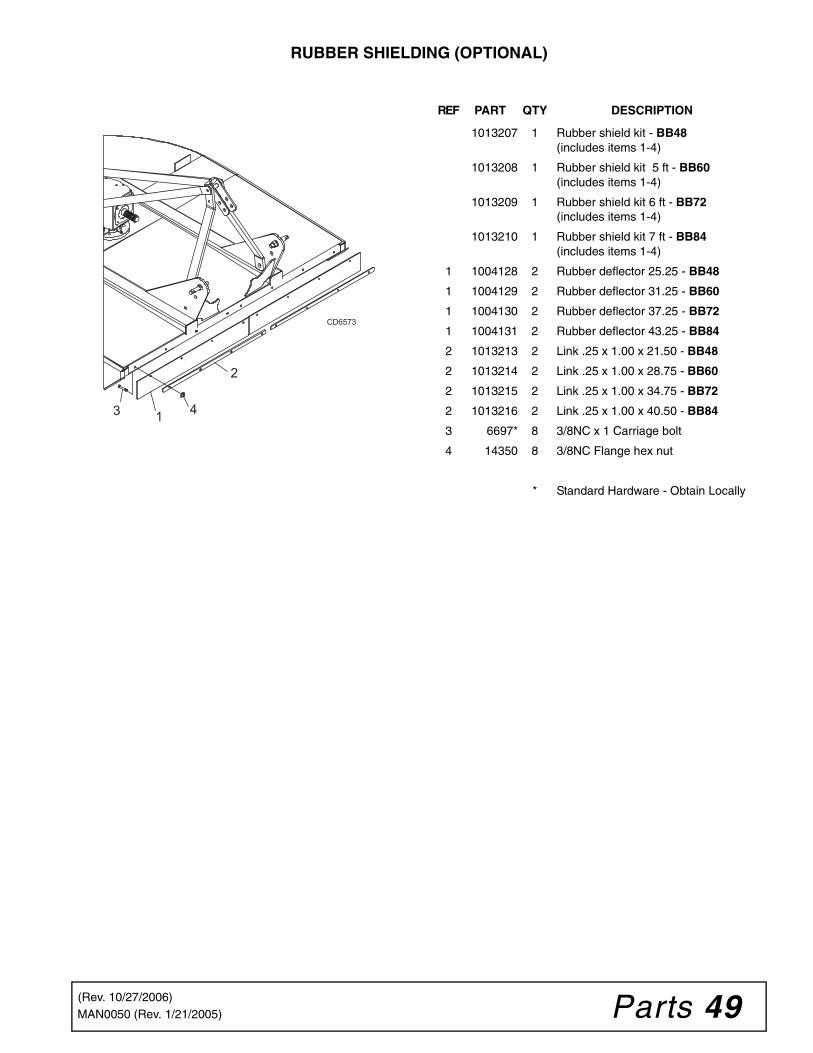
Parts 49MAN0050 (Rev. 1/21/2005)
RUBBER SHIELDING (OPTIONAL)
CD6573
1
2
3 4
REF PART QTY DESCRIPTION
1013207 1 Rubber shield kit - BB48(includes items 1-4)
1013208 1 Rubber shield kit 5 ft - BB60(includes items 1-4)
1013209 1 Rubber shield kit 6 ft - BB72(includes items 1-4)
1013210 1 Rubber shield kit 7 ft - BB84(includes items 1-4)
1 1004128 2 Rubber deflector 25.25 - BB48
1 1004129 2 Rubber deflector 31.25 - BB60
1 1004130 2 Rubber deflector 37.25 - BB72
1 1004131 2 Rubber deflector 43.25 - BB84
2 1013213 2 Link .25 x 1.00 x 21.50 - BB48
2 1013214 2 Link .25 x 1.00 x 28.75 - BB60
2 1013215 2 Link .25 x 1.00 x 34.75 - BB72
2 1013216 2 Link .25 x 1.00 x 40.50 - BB84
3 6697* 8 3/8NC x 1 Carriage bolt
4 14350 8 3/8NC Flange hex nut
* Standard Hardware - Obtain Locally
(Rev. 10/27/2006)
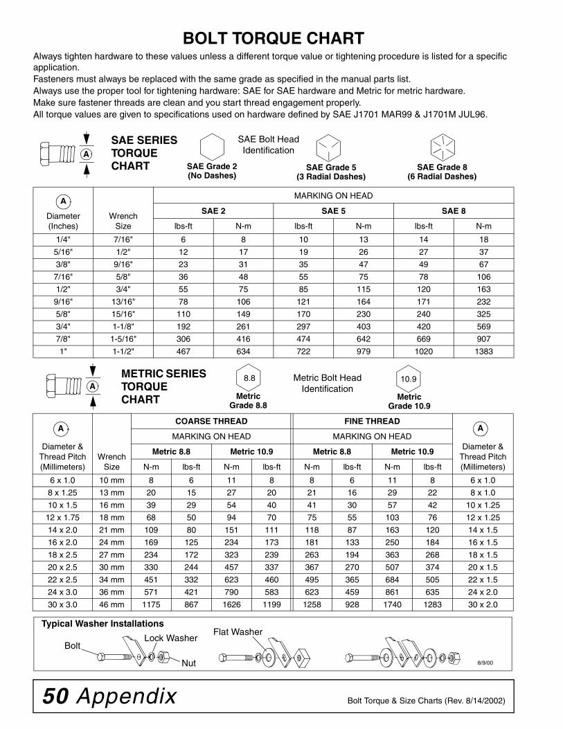
50 Appendix Bolt Torque & Size Charts (Rev. 8/14/2002)
BOLT TORQUE CHARTAlways tighten hardware to these values unless a different torque value or tightening procedure is listed for a specific application.Fasteners must always be replaced with the same grade as specified in the manual parts list.Always use the proper tool for tightening hardware: SAE for SAE hardware and Metric for metric hardware.Make sure fastener threads are clean and you start thread engagement properly. All torque values are given to specifications used on hardware defined by SAE J1701 MAR99 & J1701M JUL96.
Diameter (Inches)
WrenchSize
MARKING ON HEAD
SAE 2 SAE 5 SAE 8
lbs-ft N-m lbs-ft N-m lbs-ft N-m
1/4" 7/16" 6 8 10 13 14 18
5/16" 1/2" 12 17 19 26 27 37
3/8" 9/16" 23 31 35 47 49 67
7/16" 5/8" 36 48 55 75 78 106
1/2" 3/4" 55 75 85 115 120 163
9/16" 13/16" 78 106 121 164 171 232
5/8" 15/16" 110 149 170 230 240 325
3/4" 1-1/8" 192 261 297 403 420 569
7/8" 1-5/16" 306 416 474 642 669 907
1" 1-1/2" 467 634 722 979 1020 1383
A
SAE SERIES TORQUE CHART
SAE Bolt Head Identification
SAE Grade 2(No Dashes)
SAE Grade 5(3 Radial Dashes)
SAE Grade 8(6 Radial Dashes)
Diameter & Thread Pitch (Millimeters)
Wrench Size
COARSE THREAD FINE THREAD
Diameter & Thread Pitch (Millimeters)
MARKING ON HEAD MARKING ON HEAD
Metric 8.8 Metric 10.9 Metric 8.8 Metric 10.9
N-m lbs-ft N-m lbs-ft N-m lbs-ft N-m lbs-ft
6 x 1.0 10 mm 8 6 11 8 8 6 11 8 6 x 1.0
8 x 1.25 13 mm 20 15 27 20 21 16 29 22 8 x 1.0
10 x 1.5 16 mm 39 29 54 40 41 30 57 42 10 x 1.25
12 x 1.75 18 mm 68 50 94 70 75 55 103 76 12 x 1.25
14 x 2.0 21 mm 109 80 151 111 118 87 163 120 14 x 1.5
16 x 2.0 24 mm 169 125 234 173 181 133 250 184 16 x 1.5
18 x 2.5 27 mm 234 172 323 239 263 194 363 268 18 x 1.5
20 x 2.5 30 mm 330 244 457 337 367 270 507 374 20 x 1.5
22 x 2.5 34 mm 451 332 623 460 495 365 684 505 22 x 1.5
24 x 3.0 36 mm 571 421 790 583 623 459 861 635 24 x 2.0
30 x 3.0 46 mm 1175 867 1626 1199 1258 928 1740 1283 30 x 2.0
METRIC SERIES TORQUE CHART
Metric Bolt Head Identification
8.8
MetricGrade 10.9
10.9
MetricGrade 8.8
A
Typical Washer Installations
BoltLock Washer
Flat Washer
Nut 8/9/00
A
A
A

Appendix 51Bolt Torque & Size Charts (Rev. 8/14/2002)
BOLT SIZE CHARTNOTE: Chart shows bolt thread sizes and corresponding head (wrench) sizes for standard SAE and metric bolts.
5/16 3/8 1/2 5/8 3/4 7/8SAE Bolt Thread Sizes
MM 25 50 75 100 125 150 175
IN 1 2 3 4 5 6 7
Metric Bolt Thread Sizes8MM 18MM14MM12MM10MM 16MM
ABBREVIATIONSAG.............................................................Agriculture
ATF...............................Automatic Transmission Fluid
BSPP ...........................British Standard Pipe Parallel
BSPTM...............British Standard Pipe Tapered Male
CV .................................................. Constant Velocity
CCW ............................................ Counter-Clockwise
CW ............................................................. Clockwise
F..................................................................... Female
GA................................................................... Gauge
GR (5, etc.) ......................................... Grade (5, etc.)
HHCS.......................................Hex Head Cap Screw
HT ......................................................... Heat-Treated
JIC............... Joint Industry Council 37° Degree Flare
LH ...............................................................Left Hand
LT ......................................................................... Left
m .......................................................................Meter
mm ..............................................................Millimeter
M ........................................................................ Male
MPa........................................................Mega Pascal
N .................................................................... Newton
NC.................................................... National Coarse
NF .........................................................National Fine
NPSM................... National Pipe Straight Mechanical
NPT.........................................National Pipe Tapered
NPT SWF........National Pipe Tapered Swivel Female
ORBM .........................................O-Ring Boss - Male
P......................................................................... Pitch
PBY.....................................................Power-Beyond
psi ........................................Pounds per Square Inch
PTO....................................................Power Take Off
QD.................................................. Quick Disconnect
RH............................................................ Right Hand
ROPS......................... Roll-Over Protective Structure
RPM ...................................... Revolutions Per Minute
RT ......................................................................Right
SAE........................ Society of Automotive Engineers
UNC ................................................... Unified Coarse
UNF.........................................................Unified Fine
UNS ................................................... Unified Special
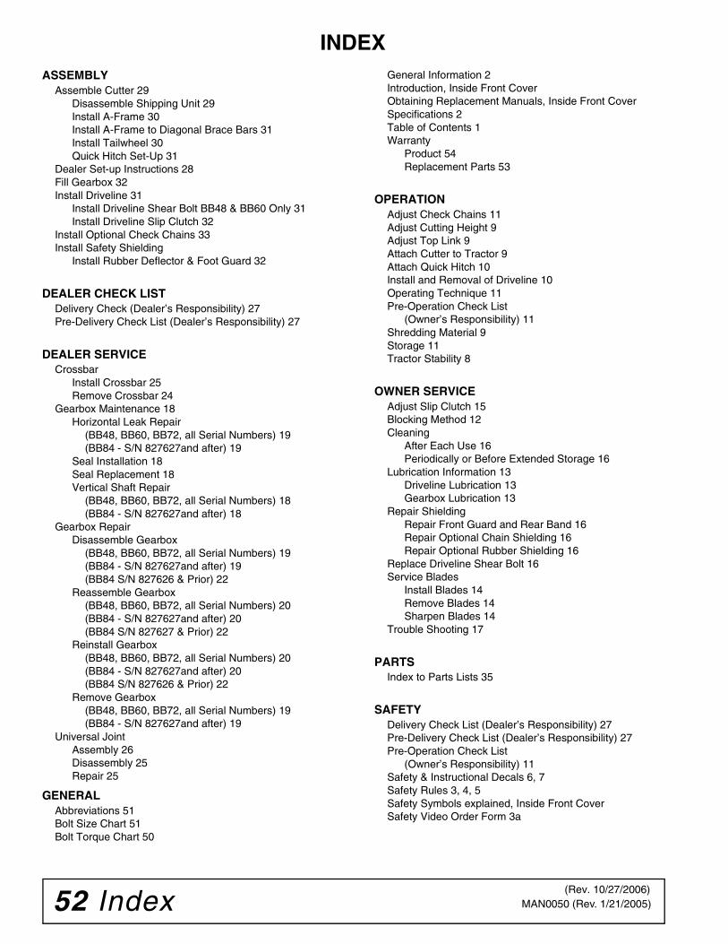
52 Index MAN0050 (Rev. 1/21/2005)
INDEXASSEMBLY
Assemble Cutter 29Disassemble Shipping Unit 29Install A-Frame 30Install A-Frame to Diagonal Brace Bars 31Install Tailwheel 30Quick Hitch Set-Up 31
Dealer Set-up Instructions 28Fill Gearbox 32Install Driveline 31
Install Driveline Shear Bolt BB48 & BB60 Only 31Install Driveline Slip Clutch 32
Install Optional Check Chains 33Install Safety Shielding
Install Rubber Deflector & Foot Guard 32
DEALER CHECK LISTDelivery Check (Dealer’s Responsibility) 27Pre-Delivery Check List (Dealer’s Responsibility) 27
DEALER SERVICECrossbar
Install Crossbar 25Remove Crossbar 24
Gearbox Maintenance 18Horizontal Leak Repair
(BB48, BB60, BB72, all Serial Numbers) 19(BB84 - S/N 827627and after) 19
Seal Installation 18Seal Replacement 18Vertical Shaft Repair
(BB48, BB60, BB72, all Serial Numbers) 18(BB84 - S/N 827627and after) 18
Gearbox RepairDisassemble Gearbox
(BB48, BB60, BB72, all Serial Numbers) 19(BB84 - S/N 827627and after) 19(BB84 S/N 827626 & Prior) 22
Reassemble Gearbox(BB48, BB60, BB72, all Serial Numbers) 20(BB84 - S/N 827627and after) 20(BB84 S/N 827627 & Prior) 22
Reinstall Gearbox(BB48, BB60, BB72, all Serial Numbers) 20(BB84 - S/N 827627and after) 20(BB84 S/N 827626 & Prior) 22
Remove Gearbox(BB48, BB60, BB72, all Serial Numbers) 19(BB84 - S/N 827627and after) 19
Universal JointAssembly 26Disassembly 25Repair 25
GENERALAbbreviations 51Bolt Size Chart 51Bolt Torque Chart 50
General Information 2Introduction, Inside Front CoverObtaining Replacement Manuals, Inside Front CoverSpecifications 2Table of Contents 1Warranty
Product 54Replacement Parts 53
OPERATIONAdjust Check Chains 11Adjust Cutting Height 9Adjust Top Link 9Attach Cutter to Tractor 9Attach Quick Hitch 10Install and Removal of Driveline 10Operating Technique 11Pre-Operation Check List
(Owner’s Responsibility) 11Shredding Material 9Storage 11Tractor Stability 8
OWNER SERVICEAdjust Slip Clutch 15Blocking Method 12Cleaning
After Each Use 16Periodically or Before Extended Storage 16
Lubrication Information 13Driveline Lubrication 13Gearbox Lubrication 13
Repair ShieldingRepair Front Guard and Rear Band 16Repair Optional Chain Shielding 16Repair Optional Rubber Shielding 16
Replace Driveline Shear Bolt 16Service Blades
Install Blades 14Remove Blades 14Sharpen Blades 14
Trouble Shooting 17
PARTSIndex to Parts Lists 35
SAFETYDelivery Check List (Dealer’s Responsibility) 27Pre-Delivery Check List (Dealer’s Responsibility) 27Pre-Operation Check List
(Owner’s Responsibility) 11Safety & Instructional Decals 6, 7Safety Rules 3, 4, 5Safety Symbols explained, Inside Front CoverSafety Video Order Form 3a
(Rev. 10/27/2006)
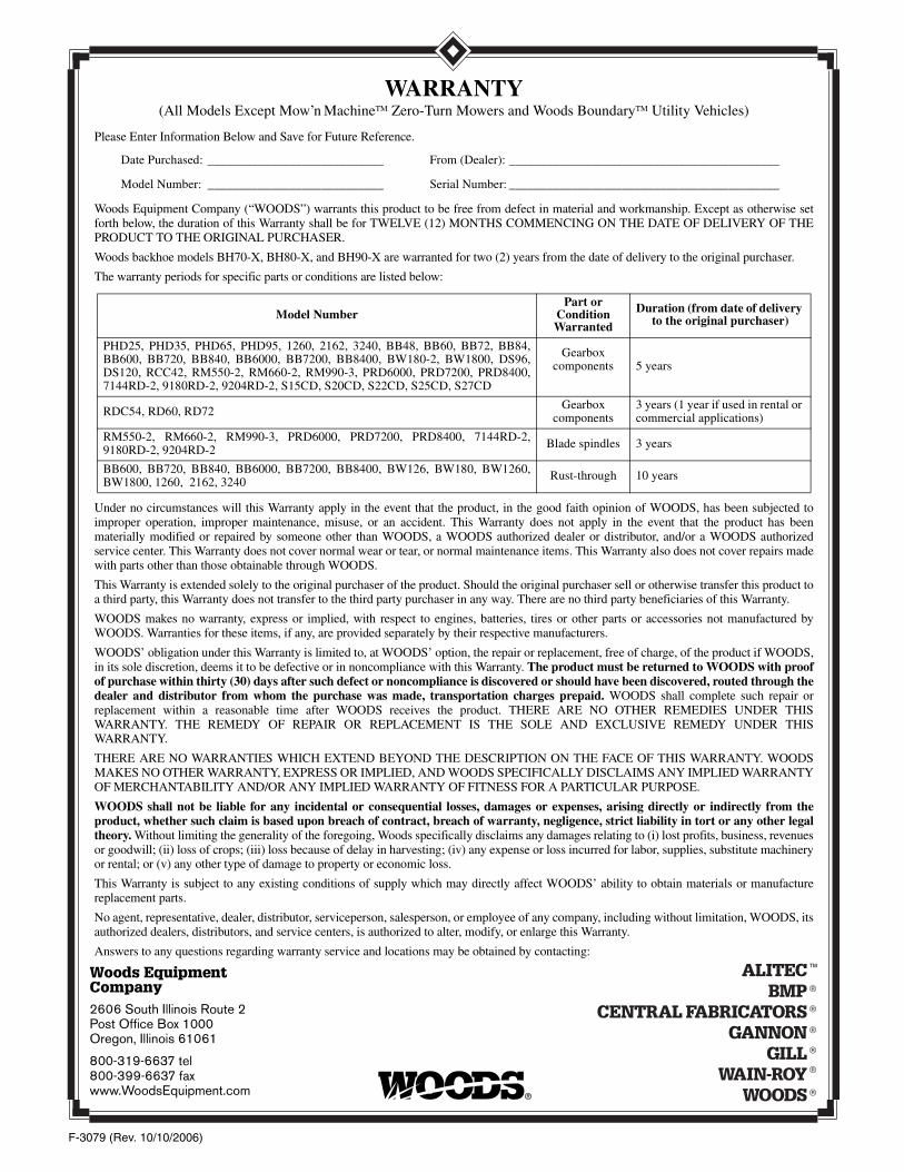
F-3079 (Rev. 10/10/2006)
Woods Equipment Company2606 South Illinois Route 2 Post Office Box 1000Oregon, Illinois 61061
800-319-6637 tel800-399-6637 faxwww.WoodsEquipment.com
WARRANTY(All Models Except Mow’n MachineTM Zero-Turn Mowers and Woods BoundaryTM Utility Vehicles)
Please Enter Information Below and Save for Future Reference.
Date Purchased: ____________________________ From (Dealer): ___________________________________________
Model Number: ____________________________ Serial Number: ___________________________________________
Woods Equipment Company (“WOODS”) warrants this product to be free from defect in material and workmanship. Except as otherwise setforth below, the duration of this Warranty shall be for TWELVE (12) MONTHS COMMENCING ON THE DATE OF DELIVERY OF THEPRODUCT TO THE ORIGINAL PURCHASER.
Woods backhoe models BH70-X, BH80-X, and BH90-X are warranted for two (2) years from the date of delivery to the original purchaser.
The warranty periods for specific parts or conditions are listed below:
Under no circumstances will this Warranty apply in the event that the product, in the good faith opinion of WOODS, has been subjected toimproper operation, improper maintenance, misuse, or an accident. This Warranty does not apply in the event that the product has beenmaterially modified or repaired by someone other than WOODS, a WOODS authorized dealer or distributor, and/or a WOODS authorizedservice center. This Warranty does not cover normal wear or tear, or normal maintenance items. This Warranty also does not cover repairs madewith parts other than those obtainable through WOODS.
This Warranty is extended solely to the original purchaser of the product. Should the original purchaser sell or otherwise transfer this product toa third party, this Warranty does not transfer to the third party purchaser in any way. There are no third party beneficiaries of this Warranty.
WOODS makes no warranty, express or implied, with respect to engines, batteries, tires or other parts or accessories not manufactured byWOODS. Warranties for these items, if any, are provided separately by their respective manufacturers.
WOODS’ obligation under this Warranty is limited to, at WOODS’ option, the repair or replacement, free of charge, of the product if WOODS,in its sole discretion, deems it to be defective or in noncompliance with this Warranty. The product must be returned to WOODS with proofof purchase within thirty (30) days after such defect or noncompliance is discovered or should have been discovered, routed through thedealer and distributor from whom the purchase was made, transportation charges prepaid. WOODS shall complete such repair orreplacement within a reasonable time after WOODS receives the product. THERE ARE NO OTHER REMEDIES UNDER THISWARRANTY. THE REMEDY OF REPAIR OR REPLACEMENT IS THE SOLE AND EXCLUSIVE REMEDY UNDER THISWARRANTY.
THERE ARE NO WARRANTIES WHICH EXTEND BEYOND THE DESCRIPTION ON THE FACE OF THIS WARRANTY. WOODSMAKES NO OTHER WARRANTY, EXPRESS OR IMPLIED, AND WOODS SPECIFICALLY DISCLAIMS ANY IMPLIED WARRANTYOF MERCHANTABILITY AND/OR ANY IMPLIED WARRANTY OF FITNESS FOR A PARTICULAR PURPOSE.
WOODS shall not be liable for any incidental or consequential losses, damages or expenses, arising directly or indirectly from theproduct, whether such claim is based upon breach of contract, breach of warranty, negligence, strict liability in tort or any other legaltheory. Without limiting the generality of the foregoing, Woods specifically disclaims any damages relating to (i) lost profits, business, revenuesor goodwill; (ii) loss of crops; (iii) loss because of delay in harvesting; (iv) any expense or loss incurred for labor, supplies, substitute machineryor rental; or (v) any other type of damage to property or economic loss.
This Warranty is subject to any existing conditions of supply which may directly affect WOODS’ ability to obtain materials or manufacturereplacement parts.
No agent, representative, dealer, distributor, serviceperson, salesperson, or employee of any company, including without limitation, WOODS, itsauthorized dealers, distributors, and service centers, is authorized to alter, modify, or enlarge this Warranty.
Answers to any questions regarding warranty service and locations may be obtained by contacting:
Model NumberPart or
Condition Warranted
Duration (from date of delivery to the original purchaser)
PHD25, PHD35, PHD65, PHD95, 1260, 2162, 3240, BB48, BB60, BB72, BB84,BB600, BB720, BB840, BB6000, BB7200, BB8400, BW180-2, BW1800, DS96,DS120, RCC42, RM550-2, RM660-2, RM990-3, PRD6000, PRD7200, PRD8400,7144RD-2, 9180RD-2, 9204RD-2, S15CD, S20CD, S22CD, S25CD, S27CD
Gearbox components 5 years
RDC54, RD60, RD72 Gearbox components
3 years (1 year if used in rental or commercial applications)
RM550-2, RM660-2, RM990-3, PRD6000, PRD7200, PRD8400, 7144RD-2,9180RD-2, 9204RD-2 Blade spindles 3 years
BB600, BB720, BB840, BB6000, BB7200, BB8400, BW126, BW180, BW1260,BW1800, 1260, 2162, 3240 Rust-through 10 years

F-8494 (Rev. 6/23/2005)
©2000 Woods Equipment Company. All rights reserved. WOODS, the Woods logo, and "Tested. Proven. Unbeatable." are trademarks of WoodsEquipment Company. All other trademarks, trade names, or service marks not owned by Woods Equipment Company that appear in this manual arethe property of their respective companies or mark holders. Specifications subject to change without notice.
WARRANTY(Replacement Parts For All Models Except Mow’n MachineTM
Zero-Turn Mowers and Woods BoundaryTM Utility Vehicles)
Woods Equipment Company (“WOODS”) warrants this product to be free from defect in material andworkmanship for a period of ninety (90) days from the date of delivery of the product to the original purchaserwith the exception of V-belts, which will be free of defect in material and workmanship for a period of 12 months.
Under no circumstances will this Warranty apply in the event that the product, in the good faith opinion ofWOODS, has been subjected to improper operation, improper maintenance, misuse, or an accident. This Warrantydoes not cover normal wear or tear, or normal maintenance items.
This Warranty is extended solely to the original purchaser of the product. Should the original purchaser sell orotherwise transfer this product to a third party, this Warranty does not transfer to the third party purchaser in anyway. There are no third party beneficiaries of this Warranty.
WOODS’ obligation under this Warranty is limited to, at WOODS’ option, the repair or replacement, free ofcharge, of the product if WOODS, in its sole discretion, deems it to be defective or in noncompliance with thisWarranty. The product must be returned to WOODS with proof of purchase within thirty (30) days aftersuch defect or noncompliance is discovered or should have been discovered, routed through the dealer anddistributor from whom the purchase was made, transportation charges prepaid. WOODS shall completesuch repair or replacement within a reasonable time after WOODS receives the product. THERE ARE NOOTHER REMEDIES UNDER THIS WARRANTY. THE REMEDY OF REPAIR OR REPLACEMENT IS THESOLE AND EXCLUSIVE REMEDY UNDER THIS WARRANTY.
THERE ARE NO WARRANTIES WHICH EXTEND BEYOND THE DESCRIPTION ON THE FACE OF THISWARRANTY. WOODS MAKES NO OTHER WARRANTY, EXPRESS OR IMPLIED, AND WOODSSPECIFICALLY DISCLAIMS ANY IMPLIED WARRANTY OF MERCHANTABILITY AND/OR ANYIMPLIED WARRANTY OF FITNESS FOR A PARTICULAR PURPOSE.
WOODS shall not be liable for any incidental or consequential losses, damages or expenses, arising directlyor indirectly from the product, whether such claim is based upon breach of contract, breach of warranty,negligence, strict liability in tort or any other legal theory. Without limiting the generality of the foregoing,Woods specifically disclaims any damages relating to (i) lost profits, business, revenues or goodwill; (ii) loss ofcrops; (iii) loss because of delay in harvesting; (iv) any expense or loss incurred for labor, supplies, substitutemachinery or rental; or (v) any other type of damage to property or economic loss.
This Warranty is subject to any existing conditions of supply which may directly affect WOODS’ ability to obtainmaterials or manufacture replacement parts.
No agent, representative, dealer, distributor, service person, salesperson, or employee of any company, includingwithout limitation, WOODS, its authorized dealers, distributors, and service centers, is authorized to alter, modify,or enlarge this Warranty.
Answers to any questions regarding warranty service and locations may be obtained by contacting: