bs 1825-2 grease separators
TRANSCRIPT
7/27/2019 BS 1825-2 Grease Separators
http://slidepdf.com/reader/full/bs-1825-2-grease-separators 1/30
BRITISH STANDARD BS EN1825-2:2002
Grease separators —Part 2: Selection of nominal size,installation, operation andmaintenance
The European Standard EN 1825-2:2002 has the status of aBritish Standard
ICS 13.060.99
NO COPYING WITHOUT BSI PERMISSION EXCEPT AS PERMITTED BY COPYRIGHT LAW
7/27/2019 BS 1825-2 Grease Separators
http://slidepdf.com/reader/full/bs-1825-2-grease-separators 2/30
BS EN 1825-2:2002
This British Standard, havingbeen prepared under thedirection of the Building andCivil Engineering Sector Policyand Strategy Committee, was
published under the authorityof the Standards Policy andStrategy Committee on29 March 2002
© BSI 29 March 2002
ISBN 0 580 38215 X
National foreword
This British Standard is the official English language version ofEN 1825-2:2002.
The UK participation in its preparation was entrusted to Technical Committee
B/505, Wastewater engineering, which has the responsibility to:
A list of organizations represented on this committee can be obtained onrequest to its secretary.
Cross-referencesThe British Standards which implement international or Europeanpublications referred to in this document may be found in the BSI StandardsCatalogue under the section entitled “International Standards CorrespondenceIndex”, or by using the “Find” facility of the BSI Standards ElectronicCatalogue.
A British Standard does not purport to include all the necessary provisions ofa contract. Users of British Standards are responsible for their correctapplication.
Compliance with a British Standard does not of itself confer immunityfrom legal obligations.
— aid enquirers to understand the text;
— present to the responsible European committee any enquiries on theinterpretation, or proposals for change, and keep the UK interestsinformed;
— monitor related international and European developments andpromulgate them in the UK.
Summary of pagesThis document comprises a front cover, an inside front cover, the EN title page,pages 2 to 27 and a back cover.
The BSI copyright date displayed in this document indicates when thedocument was last issued.
Amendments issued since publication
Amd. No. Date Comments
7/27/2019 BS 1825-2 Grease Separators
http://slidepdf.com/reader/full/bs-1825-2-grease-separators 3/30
EUROPEAN STANDARD
NORME EUROPÉENNE
EUROPÄISCHE NORM
EN 1825-2
February 2002
ICS 13.060.30
English version
Grease separators - Part 2: Selection of nominal size,installation, operation and maintenance
Installations de séparation de graisses - Partie 2: Choix destailles nominales, installation, service et entretien
Abscheideranlagen für Fette - Teil 2: Wahl der Nenngröße,Einbau, Betrieb und Wartung
This European Standard was approved by CEN on 29 September 2001.
CEN members are bound to comply with the CEN/CENELEC Internal Regulations which stipulate the conditions for giving this EuropeanStandard the status of a national standard without any alteration. Up-to-date lists and bibliographical references concerning such nationalstandards may be obtained on application to the Management Centre or to any CEN member.
This European Standard exists in three official versions (English, French, German). A version in any other language made by translationunder the responsibility of a CEN member into its own language and notified to the Management Centre has the same status as the officialversions.
CEN members are the national standards bodies of Austria, Belgium, Czech Republic, Denmark, Finland, France, Germany, Greece,Iceland, Ireland, Italy, Luxembourg, Malta, Netherlands, Norway, Portugal, Spain, Sweden, Switzerland and United Kingdom.
EUROPEAN COMMITTEE FOR STANDARDIZATION
COMIT É E UROPÉ E N DE NORMAL ISAT ION
EUROPÄISCHES KOMITEE FÜR NORMUNG
Management Centre: rue de Stassart, 36 B-1050 Brussels
© 2002 CEN All rights of exploitation in any form and by any means reservedworldwide for CEN national Members.
Ref. No. EN 1825-2:2002 E
7/27/2019 BS 1825-2 Grease Separators
http://slidepdf.com/reader/full/bs-1825-2-grease-separators 4/30
EN 1825-2:2002 (E)
2
Contents
page
Foreword......................................................................................................................................................................3
1 Scope ..............................................................................................................................................................3
2 Normative references ....................................................................................................................................3
3 Terms and definitions....................................................................................................................................3
4 Application......................................................................................................................................................4
5 Nominal size ...................................................................................................................................................5
6 Selection of the nominal size........................................................................................................................56.1 General............................................................................................................................................................56.2 Determination of the specific values ...........................................................................................................56.2.1 Maximum flow rate of wastewater................................................................................................................56.2.2 Temperature factor f t.....................................................................................................................................6
6.2.3 Density factor f d.............................................................................................................................................6
6.2.4 Detergent and rinsing agent factor f r ..........................................................................................................7
6.3 Special cases..................................................................................................................................................76.4 Determination of sludge trap volume ..........................................................................................................7
7 Installation ......................................................................................................................................................87.1 Limitations......................................................................................................................................................87.2 Place of installation .......................................................................................................................................87.3 Drainage to and from the separator.............................................................................................................87.4 Ventilation.......................................................................................................................................................8
8 Operation, inspection and maintenance .....................................................................................................9
Annex A (normative) Calculation of maximum wastewater flow Q s...................................................................10
A.1 Calculation based on equipment/fittings discharging into the separator .............................................10A.1.1 General..........................................................................................................................................................10A.1.2 Maximum wastewater flow rate Q s ............................................................................................................10
A.2 Method based upon the type of establishment discharging into the separator ...................................11A.2.1 General..........................................................................................................................................................11A.2.2 Maximum wastewater flow rate Q s ............................................................................................................11
Annex B (informative) Densities of greases and oils............................................................................................14Annex C (informative) Examples of determining nominal size of grease separator .........................................16C.1 Examples of calculation based on equipment/fittings discharging into the separator........................16C.2 Examples of calculation based on the type of establishment discharging into the separator ...........21
Annex D (informative) Measures to prevent grease accumulating and grease build-up in the pipelinesupstream of the grease separator..............................................................................................................26
Bibliography ..............................................................................................................................................................27
7/27/2019 BS 1825-2 Grease Separators
http://slidepdf.com/reader/full/bs-1825-2-grease-separators 5/30
EN 1825-2:2002 (E)
3
Foreword
This document EN 1825-2:2002 has been prepared by Technical Committee CEN/TC 165 "Wastewaterengineering", the secretariat of which is held by DIN.
This European Standard shall be given the status of a national standard, either by publication of an identical text orby endorsement, at the latest by August 2002, and conflicting national standards shall be withdrawn at the latest byJune 2004.
When pollution control requires the treatment of pollutants other than light liquids, additional measures might benecessary.
It is the second part of a two part standard for grease separators. Part 1 gives principles of design, performance
and testing, marking and quality control of grease separators.
Annex A is normative. The annexes B, C and D are informative.
According to the CEN/CENELEC Internal Regulations, the national standards organizations of the followingcountries are bound to implement this European Standard: Austria, Belgium, Czech Republic, Denmark, Finland,France, Germany, Greece, Iceland, Italy, Ireland, Luxembourg, Malta, Netherlands, Norway, Portugal, Spain,Sweden, Switzerland and the United Kingdom.
1 Scope
This European Standard provides guidance on the selection of nominal sizes, installation, operation and mainten-ance of grease separators manufactured in accordance with prEN 1825-1.
This standard does not apply to wastewater containing light liquids, e.g. grease or oils of mineral origin, and doesnot include treating stable emulsions of grease or oil in water.
The standard does not cover the use of biological additives (bacteria, enzymes).
2 Normative references
This European Standard incorporates by dated or undated references, provisions from other publications. Thesenormative references are cited at the appropriate places in the text, and the publications are listed hereafter. For
dated references, subsequent amendments to or revisions of any of these publications apply to this EuropeanStandard only when incorporated in it by amendment or revision. For undated references the latest edition of thepublication referred to applies (including amendments).
prEN 1825-1:2000, Grease separators — Part 1: Principles of design, performance and testing, marking and quality control.
EN 12056-2, Gravity drainage systems inside buildings — Part 2: Sanitary pipework, layout and calculation.
3 Terms and definitions
For the purposes of this European Standard the terms and definitions given in prEN 1825-1 and EN 12056-2 andthe following apply.
7/27/2019 BS 1825-2 Grease Separators
http://slidepdf.com/reader/full/bs-1825-2-grease-separators 6/30
EN 1825-2:2002 (E)
4
3.1selection of the nominal sizedetermination of the appropriate nominal size of the grease separation chamber for a specific case, based onamount and type of influent
4 Application
Grease separators shall be used wherever it is necessary to separate greases and oils of vegetable and animalorigin from wastewater, such as in trade or industrial plants/establishments, e.g.
commercial kitchens and large catering establishments, e.g. in inns, hotels, motorways service stations,canteens;
grilling, roasting and frying facilities;
food distribution points (with returnable crockery);
butcher's shops, with or without slaughtering facilities;
meat and sausage factories, with or without slaughtering facilities;
abattoirs;
poultry slaughterers;
tripe preparation plants;
animal rendering plants;
bone and glue boiling plants;
soap and stearine factories;
oil mills;
vegetable oil refineries;
margarine factories;
pickling plants;
fast-food preparation plants;
chip and crisp producers;
peanut roasting plants.
Wastewater containing a considerable proportion of grease in a non-separable form (i.e. emulsified) fromapplications such as dairy, cheese making and fish processing, or from distribution points having only dish washingfacilities, or from "wet waste compactors", will only be effectively treated in grease separators under certainconditions. The wastewater may require further treatment.
Applications where the discharged wastewater contains solids that are quick to purify (e.g. the fish industry) do not
require a sludge trap, but the grease separator shall be fitted with a strainer or screening device fitted on the inletside to retain coarse solids. Any retained solids should be removed and the separator thoroughly flushed with cleanwater before operational intervals to prevent putrefaction.
7/27/2019 BS 1825-2 Grease Separators
http://slidepdf.com/reader/full/bs-1825-2-grease-separators 7/30
EN 1825-2:2002 (E)
5
5 Nominal size
For the preferred nominal sizes (NS) see clause 4 of prEN 1825-1:2000.
Multiple separators of the same nominal size may be connected in parallel with the flow split equally between each
separator.
6 Selection of the nominal size
6.1 General
The selection of the nominal sizes shall be based on the nature and quantity of wastewater to be treated taking intoaccount:
maximum flow rate of wastewater;
maximum temperature of the wastewater;
density of grease/oils to be separated;
influence of cleansing and rinsing agents.
If a grease storage capacity greater than 40 · NS in litres is required, e.g. when more than the usual amount ofgrease is expected, the following options may be used:
1) using a larger nominal size separator than calculated or
2) creating grease storage capacity outside the separator or
3) emptying the separator more frequently than usually.
Where no specific sizing method is offered by a regulatory authority, then the nominal size of the separator shall bedetermined from the following formula:
rdtsNS f f f Q (1)
where
NS is the calculated nominal size of the separator;
Q s is the maximum flow rate of wastewater, entering the separator in litres per second;
f t is the impedient factor for the temperature of influent;
f d is the density factor for the relevant grease/oil;
f r is the impedient factor for the influence of cleansing and rinsing agents.
After calculation select the next higher preferred nominal size in accordance with clause 4 of prEN 1825-1:2000.
6.2 Determination of the specific values
6.2.1 Maximum flow rate of wastewater
The maximum flow rate of wastewater Q s shall be determined by:
7/27/2019 BS 1825-2 Grease Separators
http://slidepdf.com/reader/full/bs-1825-2-grease-separators 8/30
EN 1825-2:2002 (E)
6
a) measurement, or
b) calculation based upon catering equipment discharging into the grease separator, or
c) calculation based upon the type of establishment discharging into the grease separator, or
d) special calculation for individual cases, if acceptable by the regulatory authority.
Where data is available to determine Q s by b) or c), and the designer is unsure of the most appropriate option of
use, it is recommended that the higher of the flow rates determined from both calculations is used.
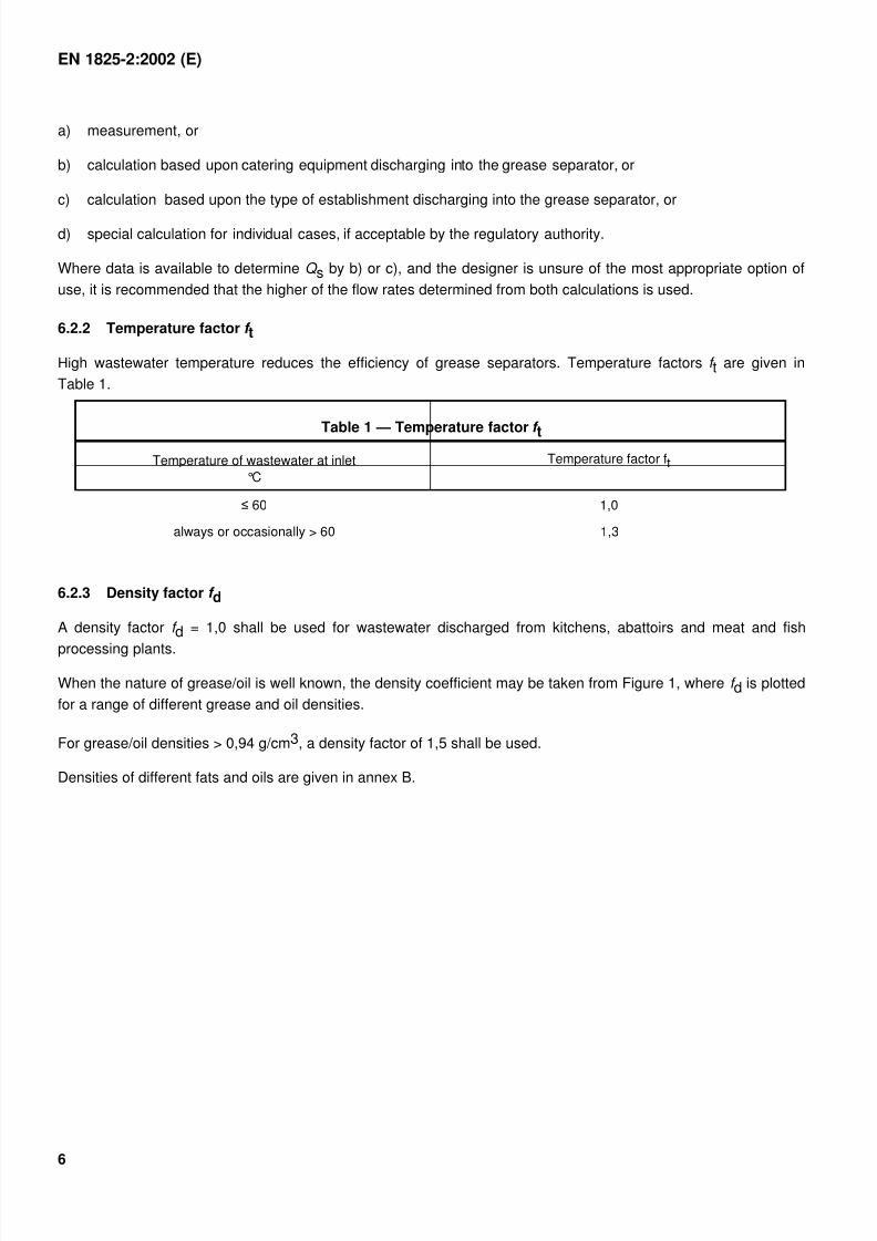
6.2.2 Temperature factor f t
High wastewater temperature reduces the efficiency of grease separators. Temperature factors f t are given in
Table 1.
Table 1 — Temperature factor f t
Temperature of wastewater at inlet
°C
Temperature factor ft
1,0
always or occasionally > 60 1,3
6.2.3 Density factor f d
A density factor f d = 1,0 shall be used for wastewater discharged from kitchens, abattoirs and meat and fish
processing plants.
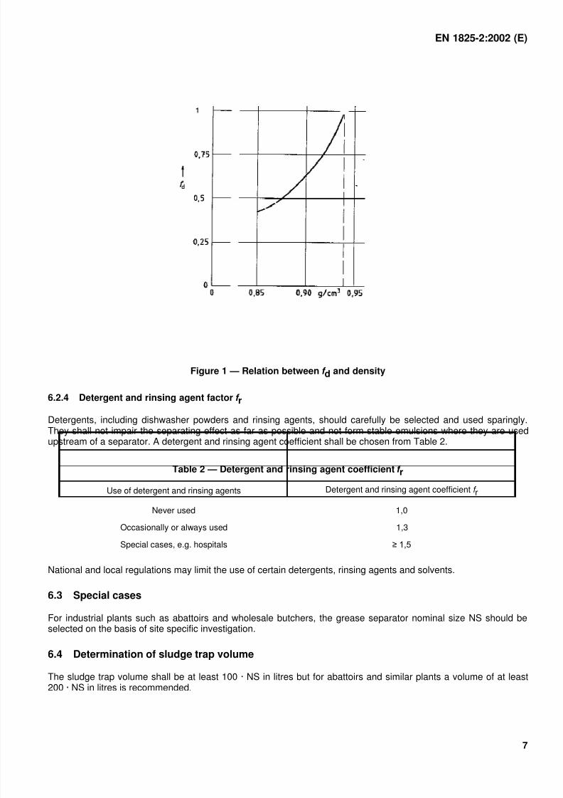
When the nature of grease/oil is well known, the density coefficient may be taken from Figure 1, where f d is plotted
for a range of different grease and oil densities.
For grease/oil densities > 0,94 g/cm3, a density factor of 1,5 shall be used.
Densities of different fats and oils are given in annex B.
7/27/2019 BS 1825-2 Grease Separators
http://slidepdf.com/reader/full/bs-1825-2-grease-separators 9/30
EN 1825-2:2002 (E)
7
Figure 1 — Relation between f d and density
6.2.4 Detergent and rinsing agent factor f r
Detergents, including dishwasher powders and rinsing agents, should carefully be selected and used sparingly.They shall not impair the separating effect as far as possible and not form stable emulsions where they are usedupstream of a separator. A detergent and rinsing agent coefficient shall be chosen from Table 2.
Table 2 — Detergent and rinsing agent coefficient f r
Use of detergent and rinsing agents Detergent and rinsing agent coefficient f r
Never used 1,0
Occasionally or always used 1,3
Special cases, e.g. hospitals
National and local regulations may limit the use of certain detergents, rinsing agents and solvents.
6.3 Special cases
For industrial plants such as abattoirs and wholesale butchers, the grease separator nominal size NS should beselected on the basis of site specific investigation.
6.4 Determination of sludge trap volume
The sludge trap volume shall be at least 100 · NS in litres but for abattoirs and similar plants a volume of at least200 · NS in litres is recommended.
7/27/2019 BS 1825-2 Grease Separators
http://slidepdf.com/reader/full/bs-1825-2-grease-separators 10/30
EN 1825-2:2002 (E)
8
7 Installation
7.1 Limitations
Only wastewater containing organic grease and oils shall be discharged to a grease separator. In particular, thefollowing shall not be discharged to a grease separator:
wastewater containing faeces ("black" water);
rainwater;
wastewater containing light liquids, e.g. grease or oil of mineral origin.
7.2 Place of installation
Grease separators should be installed close to the sources of wastewater but should not be sited in unventilatedrooms, roads, car parks or storage areas. To prevent odour and fly nuisance, separators should not be sited close
to habitable buildings, especially to opening windows and air intakes. They shall be easily accessible to cleaningvehicles. Specific operational and structural conditions may require the separator to be remotely located from thesource of wastewater.
Separators should be installed in such a way to prevent frost damage, and allow all parts requiring regularmaintenance to be easily accessible at all times.
Where necessary, manhole covers on separators shall be supported so that the load imposed on the separatordoes not exceed its design strength.
7.3 Drainage to and from the separator
Where no specific local regulations exist, grease separators shall be connected to the drains and sewers asfollows:
The wastewater to the grease separator shall be gravity fed. If the static water level in the grease separator is lowerthan the flood level (see EN 752-1), then the effluent from the separator shall be discharged to the drainage systemusing a wastewater lifting plant.
Pipelines upstream of the separator shall be laid at a minimum gradient of 2 % (1 : 50) to prevent an accumulationof grease. Where for structural and/or operational reasons, this is not possible, and/or longer pipe runs arerequired, appropriate measures shall be taken to prevent grease accumulation or deposition (see annex D).
The transition from vertical to horizontal pipes shall be made by using two 45° bends between which a piece ofpipe, at least 250 mm long, shall be placed, or by using equivalent long-radius bend. This shall be followed by a
stilling section that has a length, in millimetres, equal to at least 10 times the nominal size of the supply pipe andshall be placed upstream of the separator.
Local regulations may limit the temperature of wastewater at the point of connection to the public sewerage system.
Discharge points, e.g. floor drains, shall have traps, which, where necessary, include sediment buckets which canbe removed for cleaning purposes.
The use of sludge traps with an inlet from above, e.g. through a grating, is not permitted.
7.4 Ventilation
Pipelines connected to grease separators (upstream and downstream) shall be adequately ventilated. Thedischarge pipe to the separator shall be provided with a stack vent and branch ventilating pipes shall be connectedto all upstream branch pipes more than 5 m long.
7/27/2019 BS 1825-2 Grease Separators
http://slidepdf.com/reader/full/bs-1825-2-grease-separators 11/30
EN 1825-2:2002 (E)
9
Where the nearest vent is further than 10 m upstream of the grease separator, the supply pipe shall be fitted withan additional vent pipe, terminating as close as possible to the separator.
8 Operation, inspection and maintenance
Grease separators should be inspected, emptied and cleaned regularly. Attention is drawn to the need to complywith national or local regulations for the disposal of waste.
The frequency of inspection, emptying and cleaning should be determined with regard to the grease and sludgestorage capacity of the separator and in accordance with operational experience. Unless otherwise specified,separators should be emptied, cleaned and refilled with clean water at least once a month and, preferably, everytwo weeks.
7/27/2019 BS 1825-2 Grease Separators
http://slidepdf.com/reader/full/bs-1825-2-grease-separators 12/30
EN 1825-2:2002 (E)
10
Annex A(normative)
Calculation of maximum wastewater flow Q s
A.1 Calculation based on equipment/fittings discharging into the separator
A.1.1 General
This calculation method is based upon the number and type of equipment and fittings discharging into theseparator. It may be used for all types of kitchens, meat and fish processing plants and applies equally to existingor proposed installations.
A.1.2 Maximum wastewater flow rate Q s
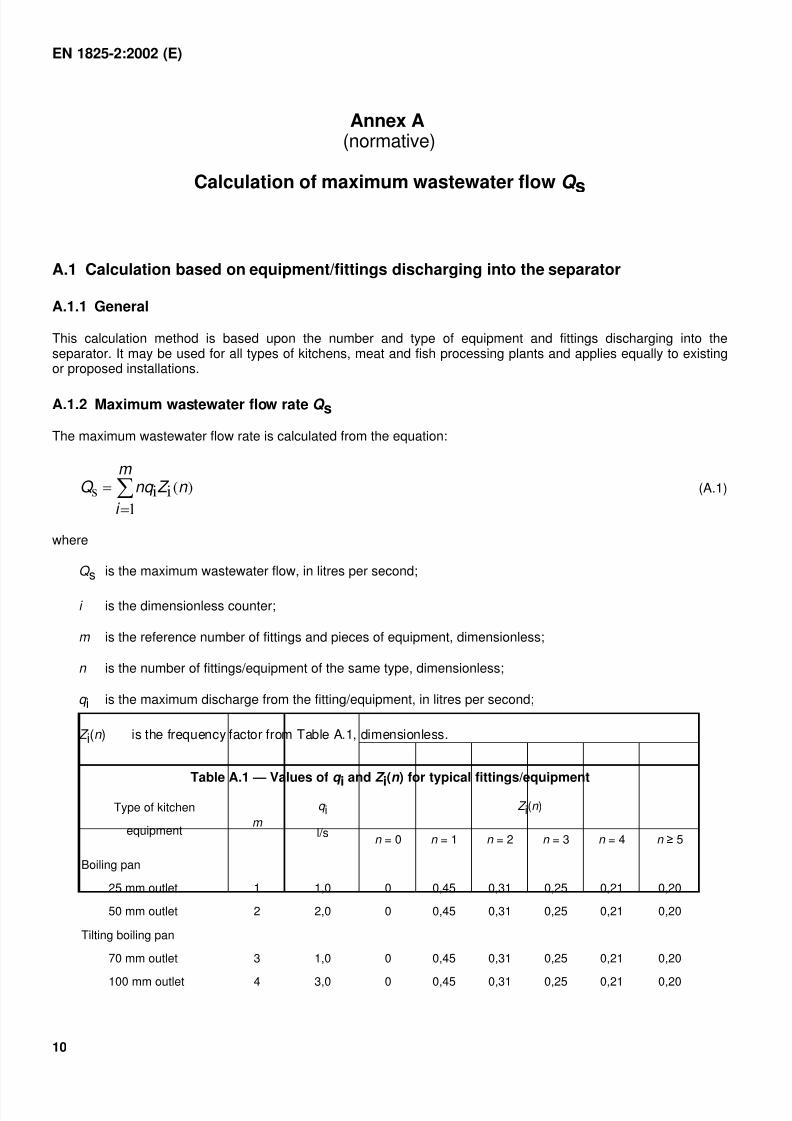
The maximum wastewater flow rate is calculated from the equation:
m
i
n Z nq Q
1
)(iis (A.1)
where
Q s is the maximum wastewater flow, in litres per second;
i is the dimensionless counter;
m is the reference number of fittings and pieces of equipment, dimensionless;
n is the number of fittings/equipment of the same type, dimensionless;
q i is the maximum discharge from the fitting/equipment, in litres per second;
Z i(n ) is the frequency factor from Table A.1, dimensionless.
Table A.1 — Values of q i and Z
i(n ) for typical fittings/equipment
Z i(n )Type of kitchen
equipmentm
q i
l/sn = 0 n = 1 n = 2 n = 3 n = 4 n
Boiling pan
25 mm outlet
50 mm outlet
1
2
1,0
2,0
0
0
0,45
0,45
0,31
0,31
0,25
0,25
0,21
0,21
0,20
0,20
Tilting boiling pan
70 mm outlet
100 mm outlet
3
4
1,0
3,0
0
0
0,45
0,45
0,31
0,31
0,25
0,25
0,21
0,21
0,20
0,20
7/27/2019 BS 1825-2 Grease Separators
http://slidepdf.com/reader/full/bs-1825-2-grease-separators 13/30
EN 1825-2:2002 (E)
11
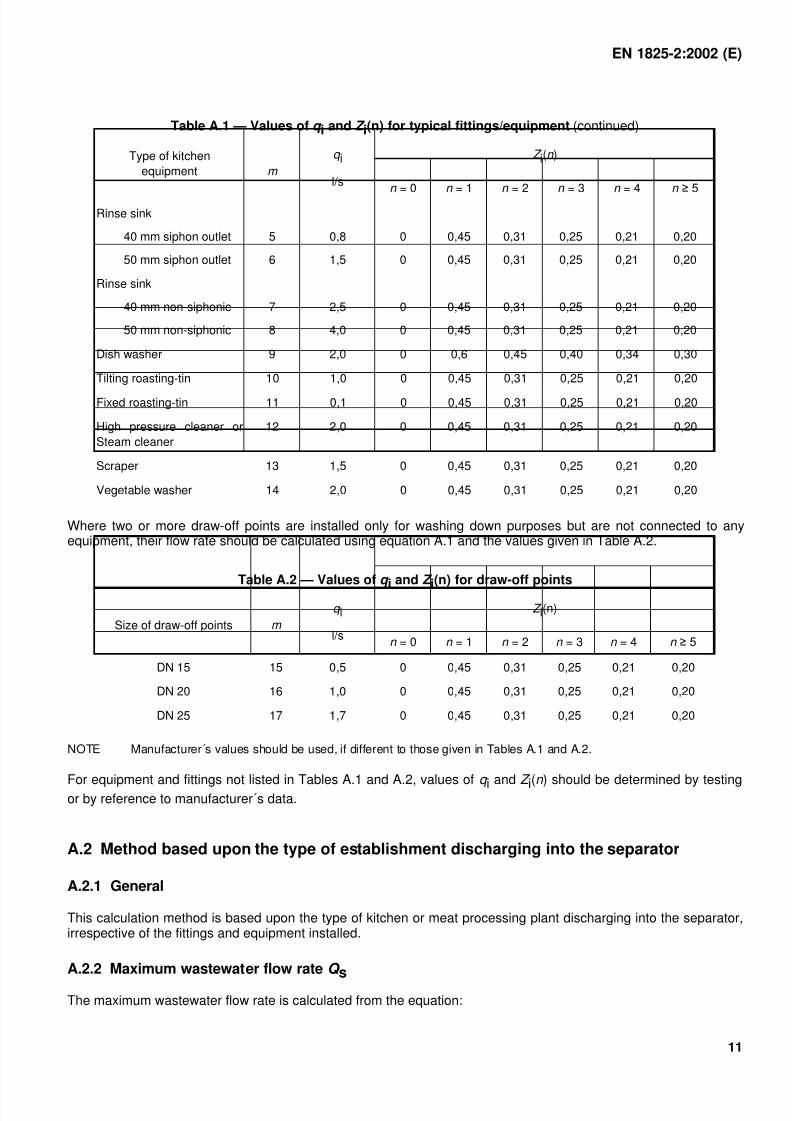
Table A.1 — Values of q i and Z i(n) for typical fittings/equipment (continued)
Z i(n )Type of kitchen
equipment m
q i
l/sn = 0 n = 1 n = 2 n = 3 n = 4 n
Rinse sink
40 mm siphon outlet
50 mm siphon outlet
5
6
0,8
1,5
0
0
0,45
0,45
0,31
0,31
0,25
0,25
0,21
0,21
0,20
0,20
Rinse sink
40 mm non-siphonic
50 mm non-siphonic
7
8
2,5
4,0
0
0
0,45
0,45
0,31
0,31
0,25
0,25
0,21
0,21
0,20
0,20
Dish washer 9 2,0 0 0,6 0,45 0,40 0,34 0,30
Tilting roasting-tin 10 1,0 0 0,45 0,31 0,25 0,21 0,20
Fixed roasting-tin 11 0,1 0 0,45 0,31 0,25 0,21 0,20
High pressure cleaner or
Steam cleaner
12 2,0 0 0,45 0,31 0,25 0,21 0,20
Scraper 13 1,5 0 0,45 0,31 0,25 0,21 0,20
Vegetable washer 14 2,0 0 0,45 0,31 0,25 0,21 0,20
Where two or more draw-off points are installed only for washing down purposes but are not connected to anyequipment, their flow rate should be calculated using equation A.1 and the values given in Table A.2.
Table A.2 — Values of q i and Z
i(n) for draw-off points
Z i(n)
Size of draw-off points m
q i
l/sn = 0 n = 1 n = 2 n = 3 n = 4 n
DN 15 15 0,5 0 0,45 0,31 0,25 0,21 0,20
DN 20 16 1,0 0 0,45 0,31 0,25 0,21 0,20
DN 25 17 1,7 0 0,45 0,31 0,25 0,21 0,20
NOTE Manufacturer´s values should be used, if different to those given in Tables A.1 and A.2.
For equipment and fittings not listed in Tables A.1 and A.2, values of q i and Z i(n ) should be determined by testingor by reference to manufacturer´s data.
A.2 Method based upon the type of establishment discharging into the separator
A.2.1 General
This calculation method is based upon the type of kitchen or meat processing plant discharging into the separator,irrespective of the fittings and equipment installed.
A.2.2 Maximum wastewater flow rate Q s
The maximum wastewater flow rate is calculated from the equation:
7/27/2019 BS 1825-2 Grease Separators
http://slidepdf.com/reader/full/bs-1825-2-grease-separators 14/30
EN 1825-2:2002 (E)
12
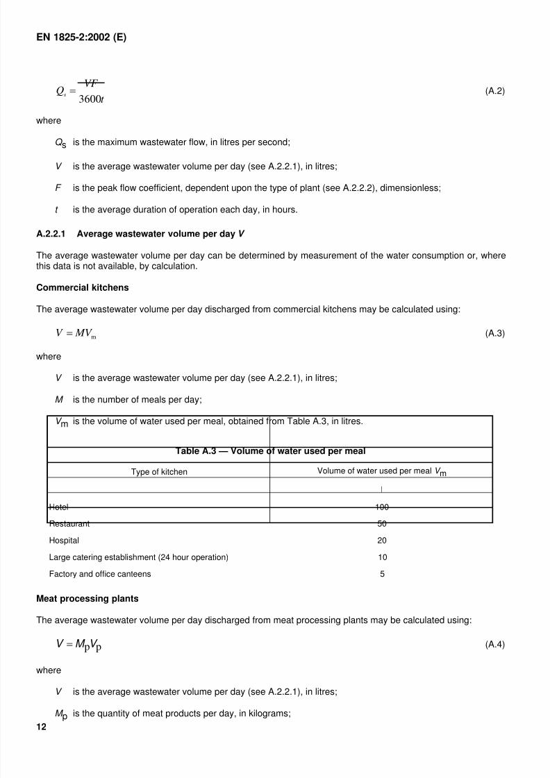
t
VF Q
s3600
(A.2)
where
Q s is the maximum wastewater flow, in litres per second;
V is the average wastewater volume per day (see A.2.2.1), in litres;
F is the peak flow coefficient, dependent upon the type of plant (see A.2.2.2), dimensionless;
t is the average duration of operation each day, in hours.
A.2.2.1 Average wastewater volume per day V
The average wastewater volume per day can be determined by measurement of the water consumption or, wherethis data is not available, by calculation.
Commercial kitchens
The average wastewater volume per day discharged from commercial kitchens may be calculated using:
m MV V (A.3)
where
V is the average wastewater volume per day (see A.2.2.1), in litres;
M is the number of meals per day;
V m is the volume of water used per meal, obtained from Table A.3, in litres.
Table A.3 — Volume of water used per meal
Type of kitchen Volume of water used per meal V m
l
Hotel 100
Restaurant 50
Hospital 20
Large catering establishment (24 hour operation) 10
Factory and office canteens 5
Meat processing plants
The average wastewater volume per day discharged from meat processing plants may be calculated using:
ppV M V (A.4)
where
V is the average wastewater volume per day (see A.2.2.1), in litres;
M p is the quantity of meat products per day, in kilograms;
7/27/2019 BS 1825-2 Grease Separators
http://slidepdf.com/reader/full/bs-1825-2-grease-separators 15/30
EN 1825-2:2002 (E)
13
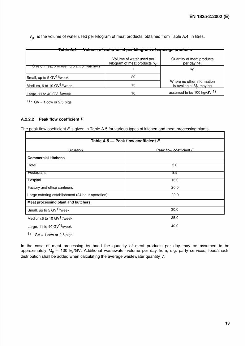
V p is the volume of water used per kilogram of meat products, obtained from Table A.4, in litres.
Table A.4 — Volume of water used per kilogram of sausage products
Size of meat processing plant or butchersVolume of water used perkilogram of meat products V p
l
Quantity of meat productsper day M p
kg
Small, up to 5 GV1) /week 20
Medium, 6 to 10 GV1) /week 15
Large, 11 to 40 GV1) /week 10
Where no other informationis available, M p may be
assumed to be 100 kg/GV 1)
1) 1 GV = 1 cow or 2,5 pigs
A.2.2.2 Peak flow coefficient F
The peak flow coefficient F is given in Table A.5 for various types of kitchen and meat processing plants.
Table A.5 — Peak flow coefficient F
Situation Peak flow coefficient F
Commercial kitchens
Hotel 5,0
Restaurant 8,5
Hospital 13,0 Factory and office canteens 20,0
Large catering establishment (24 hour operation) 22,0
Meat processing plant and butchers
Small, up to 5 GV1) /week 30,0
Medium,6 to 10 GV1) /week 35,0
Large, 11 to 40 GV1) /week 40,0
1) 1 GV = 1 cow or 2,5 pigs
In the case of meat processing by hand the quantity of meat products per day may be assumed to beapproximately M p
distribution shall be added when calculating the average wastewater quantity V .
7/27/2019 BS 1825-2 Grease Separators
http://slidepdf.com/reader/full/bs-1825-2-grease-separators 16/30
EN 1825-2:2002 (E)
14
Annex B(informative)
Densities of greases and oils
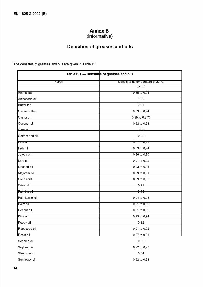
The densities of greases and oils are given in Table B.1.
Table B.1 — Densities of greases and oils
Fat/oil °C
g/cm3
Animal fat 0,85 to 0,94
Aniseseed oil 1,00
Butter fat 0,91
Cacao butter 0,89 to 0,94
Castor oil 0,95 to 0,97*)
Coconut oil 0,92 to 0,93
Corn oil 0,92
Cottonseed oil 0,92
Pine oil 0,87 to 0,91
Fish oil 0,89 to 0,94
Jojoba oil 0,86 to 0,90
Lard oil 0,91 to 0,92
Linseed oil 0,93 to 0,94
Majoram oil 0,89 to 0,91
Oleic acid 0,89 to 0,90
Olive oil 0,91
Palmitic oil 0,84
Palmkernel oil 0,94 to 0,95
Palm oil 0,91 to 0,92
Peanut oil 0,91 to 0,92
Pine oil 0,93 to 0,94
Poppy oil 0,92
Rapeseed oil 0,91 to 0,92
Resin oil 0,87 to 0,91
Sesame oil 0,92
Soybean oil 0,92 to 0,93
Stearic acid 0,84
Sunflower oil 0,92 to 0,93
7/27/2019 BS 1825-2 Grease Separators
http://slidepdf.com/reader/full/bs-1825-2-grease-separators 17/30
EN 1825-2:2002 (E)
15
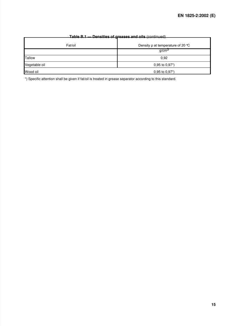
Table B.1 — Densities of greases and oils (continued)
Fat/oil °C
g/cm3
Tallow 0,92
Vegetable oil 0,95 to 0,97*)
Wood oil 0,95 to 0,97*)
*) Specific attention shall be given if fat/oil is treated in grease separator according to this standard.
7/27/2019 BS 1825-2 Grease Separators
http://slidepdf.com/reader/full/bs-1825-2-grease-separators 18/30
EN 1825-2:2002 (E)
16
Annex C(informative)
Examples of determining nominal size of grease separator
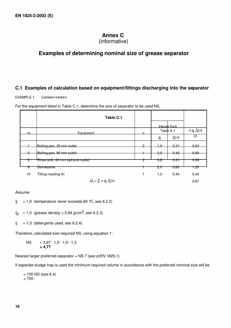
C.1 Examples of calculation based on equipment/fittings discharging into the separator
EXAMPLE 1 Canteen kitchen
For the equipment listed in Table C.1, determine the size of separator to be used NS.
Table C.1
Values from
Table A.1m Equipment n
q i Z i(n )
n q i Z i(n )
l/s
1 Boiling pan, 25 mm outlet 2 1,0 0,31 0,62
2 Boiling pan, 50 mm outlet 1 2,0 0,45 0,90
5 Rinse sink, 40 mm siphonic outlet 2 0,8 0,31 0,50
9 Dishwasher 1 2,0 0,60 1,20
10 Tilting roasting tin 1 1,0 0,45 0,45
Q s = n q i Z i(n ) 3,67
Assume:
f t = 1,0 (temperature never exceeds 60 °C, see 6.2.2)
f d = 1,0 (grease density < 0,94 g/cm3, see 6.2.3)
f r = 1,3 (detergents used, see 6.2.4)
Therefore, calculated size required NS, using equation 1:
NS = 3,67 · 1,0 · 1,0 · 1,3= 4,77
Nearest larger preferred separator = NS 7 (see prEN 1825-1)
If separate sludge trap is used the minimum required volume in accordance with the preferred nominal size will be
= 100 NS (see 6.4)= 700 l
7/27/2019 BS 1825-2 Grease Separators
http://slidepdf.com/reader/full/bs-1825-2-grease-separators 19/30
EN 1825-2:2002 (E)
17
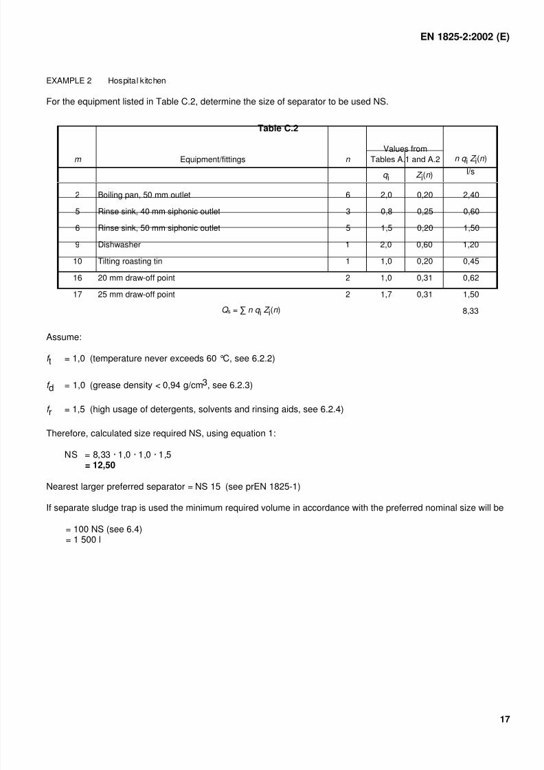
EXAMPLE 2 Hospital kitchen
For the equipment listed in Table C.2, determine the size of separator to be used NS.
Table C.2
Values from
Tables A.1 and A.2m Equipment/fittings n
q i Z i(n )
n q i Z i(n )
l/s
2 Boiling pan, 50 mm outlet 6 2,0 0,20 2,40
5 Rinse sink, 40 mm siphonic outlet 3 0,8 0,25 0,60
6 Rinse sink, 50 mm siphonic outlet 5 1,5 0,20 1,50
9 Dishwasher 1 2,0 0,60 1,20
10 Tilting roasting tin 1 1,0 0,20 0,45
16 20 mm draw-off point 2 1,0 0,31 0,62
17 25 mm draw-off point 2 1,7 0,31 1,50
Q s = n q i Z i(n ) 8,33
Assume:
f t = 1,0 (temperature never exceeds 60 °C, see 6.2.2)
f d = 1,0 (grease density < 0,94 g/cm3, see 6.2.3)
f r = 1,5 (high usage of detergents, solvents and rinsing aids, see 6.2.4)
Therefore, calculated size required NS, using equation 1:
NS = 8,33 · 1,0 · 1,0 · 1,5= 12,50
Nearest larger preferred separator = NS 15 (see prEN 1825-1)
If separate sludge trap is used the minimum required volume in accordance with the preferred nominal size will be
= 100 NS (see 6.4)
= 1 500 l
7/27/2019 BS 1825-2 Grease Separators
http://slidepdf.com/reader/full/bs-1825-2-grease-separators 20/30
EN 1825-2:2002 (E)
18
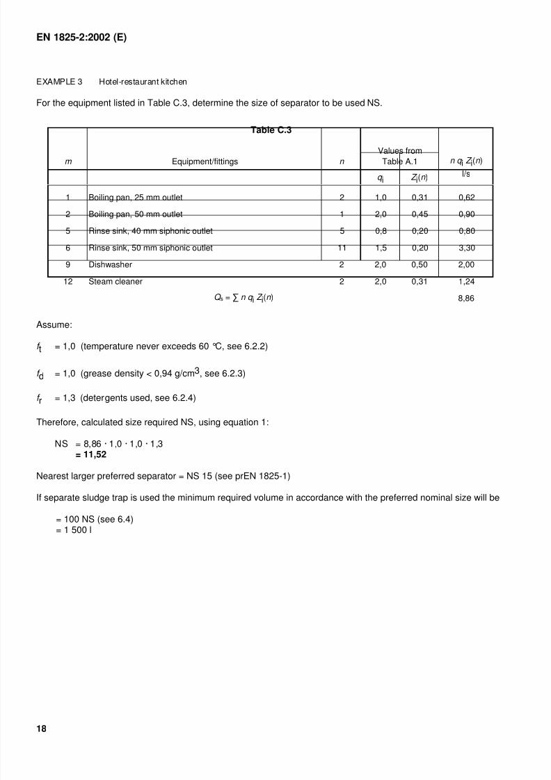
EXAMPLE 3 Hotel-restaurant kitchen
For the equipment listed in Table C.3, determine the size of separator to be used NS.
Table C.3
Values from
Table A.1m Equipment/fittings n
q i Z i(n )
n q i Z i(n )
l/s
1 Boiling pan, 25 mm outlet 2 1,0 0,31 0,62
2 Boiling pan, 50 mm outlet 1 2,0 0,45 0,90
5 Rinse sink, 40 mm siphonic outlet 5 0,8 0,20 0,80
6 Rinse sink, 50 mm siphonic outlet 11 1,5 0,20 3,30
9 Dishwasher 2 2,0 0,50 2,00
12 Steam cleaner 2 2,0 0,31 1,24
Q s = n q i Z i(n ) 8,86
Assume:
f t = 1,0 (temperature never exceeds 60 °C, see 6.2.2)
f d = 1,0 (grease density < 0,94 g/cm3, see 6.2.3)
f r = 1,3 (detergents used, see 6.2.4)
Therefore, calculated size required NS, using equation 1:
NS = 8,86 · 1,0 · 1,0 · 1,3= 11,52
Nearest larger preferred separator = NS 15 (see prEN 1825-1)
If separate sludge trap is used the minimum required volume in accordance with the preferred nominal size will be
= 100 NS (see 6.4)= 1 500 l
7/27/2019 BS 1825-2 Grease Separators
http://slidepdf.com/reader/full/bs-1825-2-grease-separators 21/30
EN 1825-2:2002 (E)
19
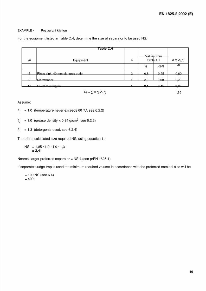
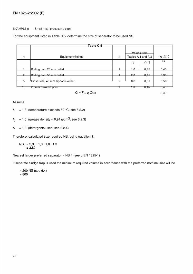
EXAMPLE 4 Restaurant kitchen
For the equipment listed in Table C.4, determine the size of separator to be used NS.
Table C.4
Values from
Table A.1m Equipment n
q i Z i(n )
n q i Z i(n )
l/s
5 Rinse sink, 40 mm siphonic outlet 3 0,8 0,25 0,60
9 Dishwasher 1 2,0 0,60 1,20
11 Fixed roasting tin 1 0,1 0,45 0,05
Q s = n q i Z i(n ) 1,85
Assume:
f t = 1,0 (temperature never exceeds 60 °C, see 6.2.2)
f d = 1,0 (grease density < 0,94 g/cm3, see 6.2.3)
f r = 1,3 (detergents used, see 6.2.4)
Therefore, calculated size required NS, using equation 1:
NS = 1,85 · 1,0 · 1,0 · 1,3= 2,41
Nearest larger preferred separator = NS 4 (see prEN 1825-1)
If separate sludge trap is used the minimum required volume in accordance with the preferred nominal size will be
= 100 NS (see 6.4)= 400 l
7/27/2019 BS 1825-2 Grease Separators
http://slidepdf.com/reader/full/bs-1825-2-grease-separators 22/30
EN 1825-2:2002 (E)
20
EXAMPLE 5 Small meat processing plant
For the equipment listed in Table C.5, determine the size of separator to be used NS.
Table C.5
Values from
Tables A.1 and A.2m Equipment/fittings n
q i Z i(n )
n q i Z i(n )
l/s
1 Boiling pan, 25 mm outlet 1 1,0 0,45 0,45
2 Boiling pan, 50 mm outlet 1 2,0 0,45 0,90
5 Rinse sink, 40 mm siphonic outlet 2 0,8 0,31 0,50
16 20 mm draw-off point 1 1,0 0,45 0,45
Q s = n q i Z i(n ) 2,30
Assume:
f t = 1,3 (temperature exceeds 60 °C, see 6.2.2)
f d = 1,0 (grease density < 0,94 g/cm3, see 6.2.3)
f r = 1,3 (detergents used, see 6.2.4)
Therefore, calculated size required NS, using equation 1:
NS = 2,30 · 1,3 · 1,0 · 1,3= 3,89
Nearest larger preferred separator = NS 4 (see prEN 1825-1)
If separate sludge trap is used the minimum required volume in accordance with the preferred nominal size will be
= 200 NS (see 6.4)= 800 l
7/27/2019 BS 1825-2 Grease Separators
http://slidepdf.com/reader/full/bs-1825-2-grease-separators 23/30
EN 1825-2:2002 (E)
21
C.2 Examples of calculation based on the type of establishment discharging into theseparator
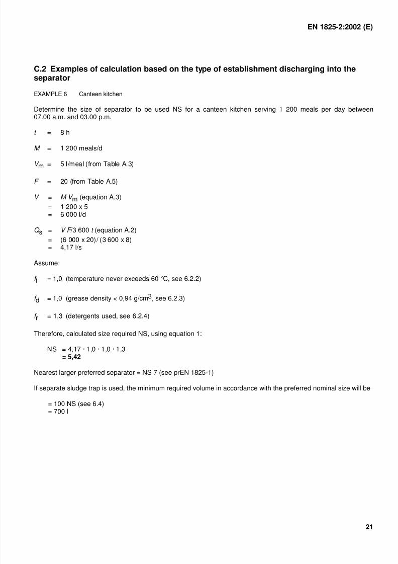
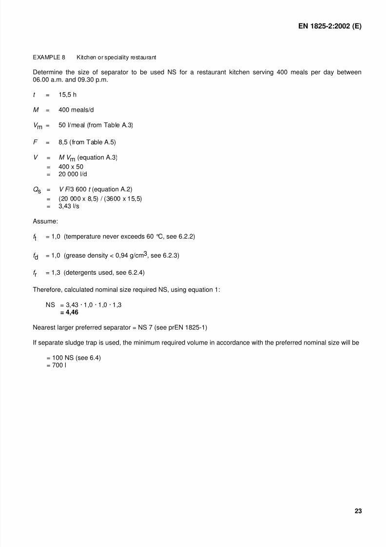
EXAMPLE 6 Canteen kitchen
Determine the size of separator to be used NS for a canteen kitchen serving 1 200 meals per day between07.00 a.m. and 03.00 p.m.
t = 8 h
M = 1 200 meals/d
V m = 5 l/meal (from Table A.3)
F = 20 (from Table A.5)
V = M V m (equation A.3)= 1 200 x 5= 6 000 l/d
Q s = V F /3 600 t (equation A.2)
= (6 000 x 20)/ (3 600 x 8)= 4,17 l/s
Assume:
f t = 1,0 (temperature never exceeds 60 °C, see 6.2.2)
f d = 1,0 (grease density < 0,94 g/cm3, see 6.2.3)
f r = 1,3 (detergents used, see 6.2.4)
Therefore, calculated size required NS, using equation 1:
NS = 4,17 · 1,0 · 1,0 · 1,3= 5,42
Nearest larger preferred separator = NS 7 (see prEN 1825-1)
If separate sludge trap is used, the minimum required volume in accordance with the preferred nominal size will be
= 100 NS (see 6.4)= 700 l
7/27/2019 BS 1825-2 Grease Separators
http://slidepdf.com/reader/full/bs-1825-2-grease-separators 24/30
EN 1825-2:2002 (E)
22
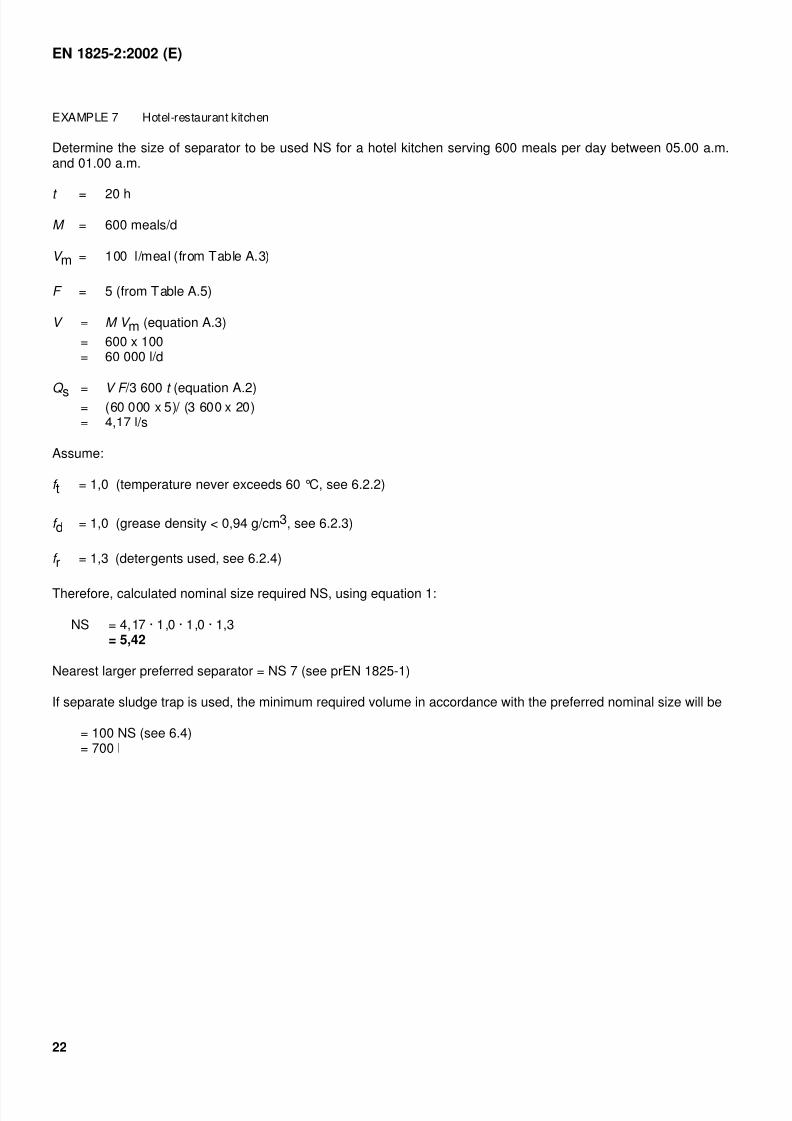
EXAMPLE 7 Hotel-restaurant kitchen
Determine the size of separator to be used NS for a hotel kitchen serving 600 meals per day between 05.00 a.m.and 01.00 a.m.
t = 20 h
M = 600 meals/d
V m = 100 l/meal (from Table A.3)
F = 5 (from Table A.5)
V = M V m (equation A.3)
= 600 x 100= 60 000 l/d
Q s = V F /3 600 t (equation A.2)= (60 000 x 5)/ (3 600 x 20)= 4,17 l/s
Assume:
f t = 1,0 (temperature never exceeds 60 °C, see 6.2.2)
f d = 1,0 (grease density < 0,94 g/cm3, see 6.2.3)
f r = 1,3 (detergents used, see 6.2.4)
Therefore, calculated nominal size required NS, using equation 1:
NS = 4,17 · 1,0 · 1,0 · 1,3= 5,42
Nearest larger preferred separator = NS 7 (see prEN 1825-1)
If separate sludge trap is used, the minimum required volume in accordance with the preferred nominal size will be
= 100 NS (see 6.4)= 700 l
7/27/2019 BS 1825-2 Grease Separators
http://slidepdf.com/reader/full/bs-1825-2-grease-separators 25/30
7/27/2019 BS 1825-2 Grease Separators
http://slidepdf.com/reader/full/bs-1825-2-grease-separators 26/30
EN 1825-2:2002 (E)
24
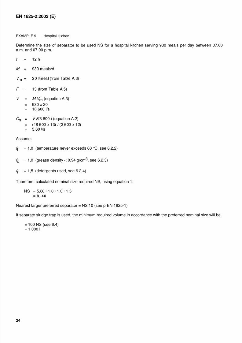
EXAMPLE 9 Hospital kitchen
Determine the size of separator to be used NS for a hospital kitchen serving 930 meals per day between 07.00a.m. and 07.00 p.m.
t = 12 h
M = 930 meals/d
V m = 20 l/meal (from Table A.3)
F = 13 (from Table A.5)
V = M V m (equation A.3)
= 930 x 20= 18 600 l/s
Q s = V F /3 600 t (equation A.2)= (18 600 x 13) / (3 600 x 12)= 5,60 l/s
Assume:
f t = 1,0 (temperature never exceeds 60 °C, see 6.2.2)
f d = 1,0 (grease density < 0,94 g/cm3, see 6.2.3)
f r = 1,5 (detergents used, see 6.2.4)
Therefore, calculated nominal size required NS, using equation 1:
NS = 5,60 · 1,0 · 1,0 · 1,5= 8,40
Nearest larger preferred separator = NS 10 (see prEN 1825-1)
If separate sludge trap is used, the minimum required volume in accordance with the preferred nominal size will be
= 100 NS (see 6.4)= 1 000 l
7/27/2019 BS 1825-2 Grease Separators
http://slidepdf.com/reader/full/bs-1825-2-grease-separators 27/30
EN 1825-2:2002 (E)
25
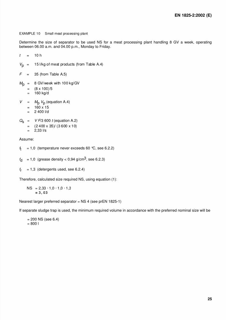
EXAMPLE 10 Small meat processing plant
Determine the size of separator to be used NS for a meat processing plant handling 8 GV a week, operatingbetween 06.00 a.m. and 04.00 p.m., Monday to Friday.
t = 10 h
V p = 15 l/kg of meat products (from Table A.4)
F = 35 (from Table A.5)
M p = 8 GV/week with 100 kg/GV
= (8 x 100)/5= 160 kg/d
V = M p V p (equation A.4)
= 160 x 15
= 2 400 l/d
Q s = V F /3 600 t (equation A.2)
= (2 400 x 35)/ (3 600 x 10)= 2,33 l/s
Assume:
f t = 1,0 (temperature never exceeds 60 °C, see 6.2.2)
f d = 1,0 (grease density < 0,94 g/cm3, see 6.2.3)
f r = 1,3 (detergents used, see 6.2.4)
Therefore, calculated size required NS, using equation (1):
NS = 2,33 · 1,0 · 1,0 · 1,3= 3,03
Nearest larger preferred separator = NS 4 (see prEN 1825-1)
If separate sludge trap is used, the minimum required volume in accordance with the preferred nominal size will be
= 200 NS (see 6.4)
= 800 l
7/27/2019 BS 1825-2 Grease Separators
http://slidepdf.com/reader/full/bs-1825-2-grease-separators 28/30
EN 1825-2:2002 (E)
26
Annex D(informative)
Measures to prevent grease accumulating and grease build-up in thepipelines upstream of the grease separator
The aim of every project should be to plan and position the system in such a way that supplementary measures toprevent grease accumulating and grease build-up in the pipelines upstream of the grease separator shall not berequired.
For structural and/or operational reasons, e.g. where longer pipe runs are required for low ambient temperatures,supplementary measures can be required, e.g. thermal insulation of pipes, or trace heating with thermal insulation.
Pipes led through cool cellars can require thermal insulation.
Pipes led through areas of buildings prone to frost, e.g. underground garages, can require trace heatingwith thermal insulation.
The temperature of trace heating should be thermostatically controlled (between 25 °C and 40 °C) to allowfor seasonal changes.
Trace heating is only useful during times that grease contaminated wastewater is flowing, therefore, atime-clock is recommended.
Pipes in heated rooms, pipes buried beneath buildings and frost-proof installed pipes installed outside buildings donot require supplementary measures, provided they have been installed in accordance with 7.3 and 7.4.
7/27/2019 BS 1825-2 Grease Separators
http://slidepdf.com/reader/full/bs-1825-2-grease-separators 29/30
EN 1825-2:2002 (E)
27
Bibliography
EN 752-1, Drain and sewer systems outside buildings — Part 1: Generalities and definitions.
7/27/2019 BS 1825-2 Grease Separators
http://slidepdf.com/reader/full/bs-1825-2-grease-separators 30/30
BS EN1825-2:2002
BSI
389 Chiswick High Road
London
W4 4AL
BSI — British Standards Institution
BSI is the independent national body responsible for preparingBritish Standards. It presents the UK view on standards in Europe and at theinternational level. It is incorporated by Royal Charter.
Revisions
British Standards are updated by amendment or revision. Users ofBritish Standards should make sure that they possess the latest amendments oreditions.
It is the constant aim of BSI to improve the quality of our products and services.We would be grateful if anyone finding an inaccuracy or ambiguity while usingthis British Standard would inform the Secretary of the technical committeeresponsible, the identity of which can be found on the inside front cover.Tel: +44 (0)20 8996 9000. Fax: +44 (0)20 8996 7400.
BSI offers members an individual updating service called PLUS which ensuresthat subscribers automatically receive the latest editions of standards.
Buying standards
Orders for all BSI, international and foreign standards publications should beaddressed to Customer Services. Tel: +44 (0)20 8996 9001.Fax: +44 (0)20 8996 7001. Email: [email protected]. Standards are alsoavailable from the BSI website at http://www.bsi-global.com.
In response to orders for international standards, it is BSI policy to supply theBSI implementation of those that have been published as British Standards,unless otherwise requested.
Information on standards
BSI provides a wide range of information on national, European andinternational standards through its Library and its Technical Help to ExportersService. Various BSI electronic information services are also available which give
details on all its products and services. Contact the Information Centre.Tel: +44 (0)20 8996 7111. Fax: +44 (0)20 8996 7048. Email: [email protected].
Subscribing members of BSI are kept up to date with standards developmentsand receive substantial discounts on the purchase price of standards. For detailsof these and other benefits contact Membership Administration.Tel: +44 (0)20 8996 7002. Fax: +44 (0)20 8996 7001.Email: [email protected].
Information regarding online access to British Standards via British StandardsOnline can be found at http://www.bsi-global.com/bsonline.
Further information about BSI is available on the BSI website athttp://www.bsi-global.com.
Copyright
Copyright subsists in all BSI publications. BSI also holds the copyright, in theUK, of the publications of the international standardization bodies. Except aspermitted under the Copyright, Designs and Patents Act 1988 no extract may bereproduced, stored in a retrieval system or transmitted in any form or by anymeans – electronic, photocopying, recording or otherwise – without prior writtenpermission from BSI.
This does not preclude the free use, in the course of implementing the standard,of necessary details such as symbols, and size, type or grade designations. If thesedetails are to be used for any other purpose than implementation then the priorwritten permission of BSI must be obtained.
Details and advice can be obtained from the Copyright & Licensing Manager.Tel: +44 (0)20 8996 7070. Fax: +44 (0)20 8996 7553.Email: [email protected].