bs 3974 pipe support
DESCRIPTION
Building Services, Plumbing, Pipe SupportTRANSCRIPT

Section 3 of this catalogue has been compiled with the kind permission of theBritish Standard Institution. All data has been taken from BS 3974 Part 1 (1974),Part 2 (1978) and Part 3 (1980). Q.P.S. reserve the right to alter specifications inline with any updates by the relevant British Standards.
Schedule of materials
Material referenceComponent Material BS no. Designation
(a) Pipe clipsClips Range A Carbon steel 4360 Grade 43A
Range B 1501: Part 1 151 or 161: grade 430B
Range D1, D1(M), D2 Alloy steel 1501: Part 2 620 grade 27BRange D3, D3(M) 1501: Part 2 622 grade 515B
All bolts and Range A, B Carbon steel 4190 Grade 4, 6studbolts
Range D1, D1(M), D2 Alloy steel 4882 661 grade B16Range D3, D3(M) 4882 1% Cr Mo V boron grade B16A
All nuts Range A, B Carbon steel 4190 Grade 4
Range D1, D1(M), D2 Alloy steel 4882 240 grade 4Range D3, D3(M) 4882 621 grade 7
Distance-pieces All ranges Carbon steel 1387 Medium or heavy
(b) U-strapsStrap Range D1, D2 Alloy steel 1501: Part 2 620 grade 27B
Range D3 1501: Part 2 622 grade 515B
Steady plate Range D1, D2, D3 Alloy steel 1501: Part 2 620 grade 27A or 27B
Yoke, end and Ranges D1, D2, D3 Carbon steel 4360 Grade 43Ahanger plates
All bolts Ranges D1, D2, D3 Carbon steel 3692 Grade 8.8All nuts 3692 Grade 8
(c) Riser ClampsClamp Range A Carbon steel 4360 Grade 43A
Range B, C 1501: Part 1 151 or 161: grade 430BClamp Range D1, D2 Alloy steel 1501: Part 2 620 grade 27Band gusset Range D3 1501: Part 2 622 grade 515B
All bolts Range A, B Carbon steel 4190 Grade 4.6Range C 3692 Grade 8.8Range D1, D2 Alloy steel 4882 661 grade B16Range D3 4882 1% Cr Mo V boron grade 816A
All nuts Range A, B Carbon steel 4190 240 grade 4Range C 3692 Grade 8Range D1, D2 Alloy steel 4882 240 grade 4Range D3 4882 621 grade 7
Distance-pieces Range A, B Carbon steel 1387 Medium or heavyRange C Alloy steel 1775 HFS13 or HFW13Range D1, D2 Carbon steel 1387 Medium or heavyRange D3 Alloy steel 3604 620
(d) Sling rods All componentsRods All ranges Carbon steel 4360 Grade 43ANuts All ranges 4190 Grade 4 or 6
(e) Pipe overstraps Carbon steel 4360 Grade 43Aand bolts
Low temperature see table 12steel in section three
(f) Pipe overstraps Copper alloy 2870 CZ 110and hookstraps
Stainless steel 1449: Part 2 17% min. Cr content
(g) Lining Lead sheet 1178 —materials forsteel pipe clips Copper/copper 2870 CZ 110when used on alloy sheetcopper/copperalloy tubes Compressed fibre — —
BS 3974 PIPE SUPPORT
Page 64

BS3974 PIPE SUPPORT
2 Bolt Pipe Clamp
3 Bolt Pipe Clamp
4 Bolt Riser Clamp
6 Bolt Riser Clamp
10 Bolt Riser Clamp(Boiler Plate)
10 Bolt Riser Clamp(Alloy Steel)
U Bolt (Non Grip)
U Bolt (Grip)
Over Strap
Beam Welding Attachs
51L/51H
57L/57H/58L/58H/59
61
62
63
64/65/66
67/68
69/70
71
72
67
67/68
70
71
72
74/75
76
77
79
79
78
78
73
80
80
81
82
82
83
79
92
93
95
96
97/98
99
100
101
Dee Shackle
1 Piece Pipe Strap
U Strap
Spring Cage
Spring Cage
Sling Rod Cage
Hookbolt (To Grip)
Hookstrap
Universal Beam Clip
DESCRIPTION FIGURE No. PAGE DESCRIPTION FIGURE No. PAGE
Page 65

BS 3974 PIPE SUPPORT
INDEX
FIG.No. DESCRIPTIONPageNo. PICTORIAL FIG.No. DESCRIPTION
PageNo. PICTORIAL
51L51H
57L57H58L58H59
61
62
63
646566
6768
6970
71
72
79
92
93
95
96
97
98
99
100
101
2 BOLTPIPE CLAMP
3 BOLTPIPE CLAMP
4 BOLTRISERCLAMP
6 BOLTRISERCLAMP
10 BOLTRISERCLAMP
(Boiler Plate)
10 BOLTRISERCLAMP
(Alloy Steel)
‘U’ BOLTSNOT TO GRIP
‘U’ BOLTSTO GRIP
OVERSTRAP
BEAMWELDING
ATTACHMENT
DEESHACKLE
1 PIECEPIPE
STRAP
‘U’ STRAP
SPRINGCAGE
SPRINGCAGE
SLING RODCAGE
SLING RODCAGE
HOOKBOLT(To Grip)
HOOKSTRAP
UNIVERSALBEAM CLIP
67
68/69
70
71
72
74/75
76
77
79
79
78
78
73
80
80
81
81
82
82
83
Page 66

BS 3974 PIPE SUPPORT
Page 67
FIG. 51 & 51H
Sling Clip Clip and load Safe Sling Clip SafeNom Outside Rod D dimensions G Working Rod D dimensions bolts G WorkingSize Dia Dia Dia B x T P Bolt Hole Ø Min load Dia Dia B x T P Bolt Hole dia Min Loadmm mm mm mm mm mm mm mm kgf mm mm mm mm mm mm kgf15 21.3 10 23 35x5 65 M10 12 15 28020 26.9 10 28 35x5 70 M10 12 15 28025 33.7 10 36 35x5 75 M10 12 15 28032 42.4 12 44 35x5 90 M12 15 18 28040 48.3 12 50 35x5 95 M12 15 18 28050 60.3 12 62 35x5 105 M12 15 18 28065 76.1 12 80 35x5 125 M12 15 18 165 16 80 35x8 155 M16 19 24 45080 88.9 12 92 35x5 135 M12 15 18 165 16 92 35x8 165 M16 19 24 450
100 114.3 12 118 35x5 170 M12 15 18 165 16 118 35x8 190 M16 19 24 450125 139.7 16 144 35x5 195 M16 19 24 280 16 144 35x8 215 M16 19 24 450150 168.3 16 172 35x5 225 M16 19 24 280 16 172 35x8 245 M16 19 24 450175 193.7 16 198 35x8 270 M16 19 24 450 16 198 45x10 280 M16 19 24 900200 219.1 16 224 35x8 295 M16 19 24 450 16 224 45x10 305 M16 19 24 900225 244.5 16 248 35x8 320 M16 19 24 450 20 248 60x10 340 M20 24 30 1350250 273.0 16 278 35x8 350 M16 19 24 450 20 278 60x10 365 M20 24 30 1350300 323.9 20 330 45x10 420 M20 24 30 900 24 330 55x15 455 M24 28 36 1800350 355.6 24 362 55x10 460 M24 28 36 900 30 362 55x15 500 M30 35 45 2250400 406.4 24 412 60x15 535 M24 28 36 1350 30 412 65x20 575 M30 35 45 2700450 457.0 30 464 65x20 625 M30 35 45 2250 36 464 80x20 635 M36 42 54 3600500 508.0 30 516 65x20 675 M30 35 45 2250 36 516 90x25 715 M36 42 54 4500550 559.0 30 566 65x20 725 M30 35 45 2250 36 566 90x25 765 M36 42 54 4500600 610.0 30 618 80x20 780 M30 35 45 2700 42 618 110x25 830 M42 48 63 5900
Pipe Size Light Series FIG 51L Heavy Series FIG 51H
USE HEAVY SERIES
boltsClip and load
Fig. 51 Dimensions of pipe clips for steel pipes (RANGE A:20ºC to 100ºC)
Pipe clip for steel, cast iron and copper/copper alloy pipes(range A: -20ºC to 100ºC
Sling G SafeRod Min Working
Nominal Outside Diameter D B x T P Bolt Hole LoadSize Diameter Diameter Size Diameter
kgf650 660 30 665 80x20 830 M30 35 45 1400700 711 30 716 80x20 880 M30 35 45 1300750 762 30 765 80x20 930 M30 35 45 1200800 813 30 816 90x25 1020 M30 35 45 2000850 864 30 868 90x25 1070 M30 35 45 1900900 914 30 918 90x25 1120 M30 35 45 1800
1000 1016 36 1020 100x30 1250 M36 42 54 2600
Pipe Clip Dimensions Clip & Load Bolts
FIG. 53 Dimensions of pipe clips for steel pipes(Range A: -20ºC to 100ºC)All dimensions are in millimetres
Material - Carbon Steel
When ordering specify:Figure No.Nominal pipe sizeFinish

BS 3974 PIPE SUPPORT
Page 68
Sling Clip Safe Sling Clip SafeNom Outside Rod D Dimensions Bolts G Working Rod D Dimensions Bolts G WorkingSize Dia Dia Dia B x T P Q Bolt Hole Ø Min Load Dia Dia B x T P Q Bolt Hole Ø Min Loadmm mm mm mm mm mm mm mm mm kgf mm mm mm mm mm mm mm kgf15 21.3 10 23 35x5 65 70 M10 12 15 28020 26.9 10 28 35x5 70 70 M10 12 15 28025 33.7 10 36 35x5 75 70 M10 12 15 28032 42.4 12 44 35x5 90 70 M12 15 18 28040 48.3 12 50 35x5 95 85 M12 15 18 28050 60.3 12 62 35x5 105 80 M12 15 18 28065 76.1 12 80 35x5 125 105 M12 15 18 165 16 80 35x8 155 90 M16 19 24 45080 88.9 12 92 35x5 135 105 M12 15 18 165 16 92 35x8 165 95 M16 19 24 450
100 114.3 12 118 35x5 170 105 M12 15 18 165 16 118 35x8 190 95 M16 19 24 450125 139.7 16 144 35x8 215 95 M16 19 24 280 16 144 35x8 215 95 M16 19 24 450150 168.3 16 172 35x8 245 95 M16 19 24 280 16 172 35x8 245 95 M16 19 24 450175 193.7 16 198 35x8 270 95 M16 19 24 280 20 198 45x10 288 85 M20 24 30 900200 219.1 16 224 35x8 295 100 M16 19 24 280 20 224 45x10 315 95 M20 24 30 900225 244.5 16 248 45x10 330 95 M16 19 24 450 20 248 55x15 365 85 M20 24 30 1350250 273.0 16 278 45x10 360 105 M16 19 24 450 20 278 55x15 390 90 M20 24 30 1350300 323.9 20 330 55x15 445 115 M20 24 30 900 24 330 65x20 475 115 M24 28 36 1800350 355.6 24 362 55x15 485 115 M24 28 36 900 30 362 65x20 525 115 M30 35 45 2250400 406.4 24 412 65x20 560 115 M24 28 36 1350 30 412 90x25 600 115 M30 35 45 2700450 457.0 30 464 65x20 625 115 M30 35 45 1800 36 464 90x25 660 115 M36 42 54 3600500 508.0 30 516 90x25 700 115 M30 35 45 2700 36 516 100x30 740 115 M36 42 54 4500550 559.0 30 566 90x25 750 15 M30 35 45 2700 36 566 100x30 790 115 M36 42 54 4500600 610.0 30 618 90x25 805 115 M30 35 45 2700 42 618 100x35 880 115 M42 48 63 5900
USE HEAVY SERIES
Pipe Size Light Series Heavy SeriesClip and load Clip and load
FIG. 57 Dimensions of pipe clips for steel pipes, Range B: -20ºC to 400ºC
Material - Carbon Steel
When ordering specify:Figure No.Nominal pipe sizeFinish
FIGS. 57/58/59
BS 3974 PIPE SUPPORT
Page 69
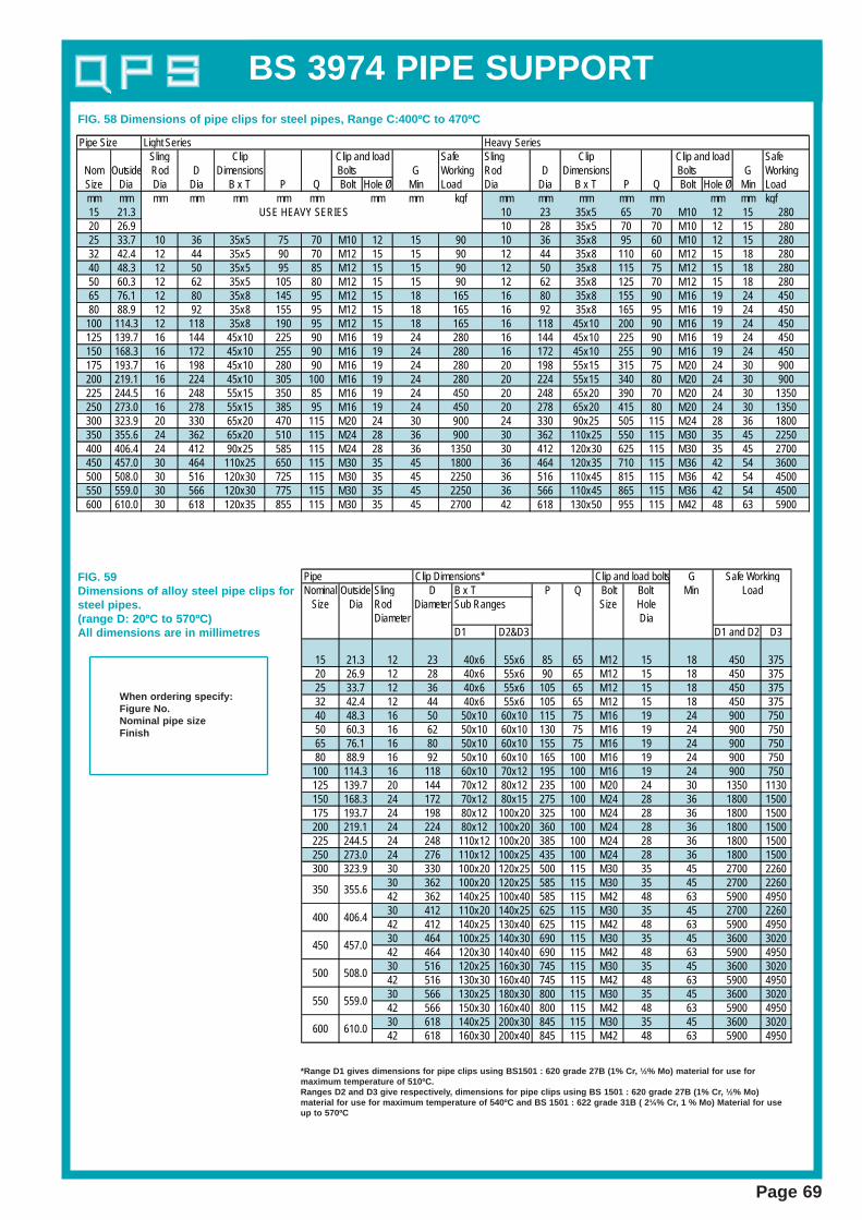
Sling Clip Safe Sling Clip SafeNom Outside Rod D Dimensions Bolts G Working Rod D Dimensions Bolts G WorkingSize Dia Dia Dia B x T P Q Bolt Hole Ø Min Load Dia Dia B x T P Q Bolt Hole Ø Min Loadmm mm mm mm mm mm mm mm mm kgf mm mm mm mm mm mm mm kgf15 21.3 10 23 35x5 65 70 M10 12 15 28020 26.9 10 28 35x5 70 70 M10 12 15 28025 33.7 10 36 35x5 75 70 M10 12 15 90 10 36 35x8 95 60 M10 12 15 28032 42.4 12 44 35x5 90 70 M12 15 15 90 12 44 35x8 110 60 M12 15 18 28040 48.3 12 50 35x5 95 85 M12 15 15 90 12 50 35x8 115 75 M12 15 18 28050 60.3 12 62 35x5 105 80 M12 15 15 90 12 62 35x8 125 70 M12 15 18 28065 76.1 12 80 35x8 145 95 M12 15 18 165 16 80 35x8 155 90 M16 19 24 45080 88.9 12 92 35x8 155 95 M12 15 18 165 16 92 35x8 165 95 M16 19 24 450
100 114.3 12 118 35x8 190 95 M12 15 18 165 16 118 45x10 200 90 M16 19 24 450125 139.7 16 144 45x10 225 90 M16 19 24 280 16 144 45x10 225 90 M16 19 24 450150 168.3 16 172 45x10 255 90 M16 19 24 280 16 172 45x10 255 90 M16 19 24 450175 193.7 16 198 45x10 280 90 M16 19 24 280 20 198 55x15 315 75 M20 24 30 900200 219.1 16 224 45x10 305 100 M16 19 24 280 20 224 55x15 340 80 M20 24 30 900225 244.5 16 248 55x15 350 85 M16 19 24 450 20 248 65x20 390 70 M20 24 30 1350250 273.0 16 278 55x15 385 95 M16 19 24 450 20 278 65x20 415 80 M20 24 30 1350300 323.9 20 330 65x20 470 115 M20 24 30 900 24 330 90x25 505 115 M24 28 36 1800350 355.6 24 362 65x20 510 115 M24 28 36 900 30 362 110x25 550 115 M30 35 45 2250400 406.4 24 412 90x25 585 115 M24 28 36 1350 30 412 120x30 625 115 M30 35 45 2700450 457.0 30 464 110x25 650 115 M30 35 45 1800 36 464 120x35 710 115 M36 42 54 3600500 508.0 30 516 120x30 725 115 M30 35 45 2250 36 516 110x45 815 115 M36 42 54 4500550 559.0 30 566 120x30 775 115 M30 35 45 2250 36 566 110x45 865 115 M36 42 54 4500600 610.0 30 618 120x35 855 115 M30 35 45 2700 42 618 130x50 955 115 M42 48 63 5900
Heavy SeriesClip and load Clip and load
Pipe Size Light Series
USE HEAVY SERIES
Clip and load bolts GNominal Outside Sling D P Q Bolt Bolt Min
Size Dia Rod Diameter Size HoleDiameter Dia
D1 D2&D3 D1 and D2 D3
15 21.3 12 23 40x6 55x6 85 65 M12 15 18 450 37520 26.9 12 28 40x6 55x6 90 65 M12 15 18 450 37525 33.7 12 36 40x6 55x6 105 65 M12 15 18 450 37532 42.4 12 44 40x6 55x6 105 65 M12 15 18 450 37540 48.3 16 50 50x10 60x10 115 75 M16 19 24 900 75050 60.3 16 62 50x10 60x10 130 75 M16 19 24 900 75065 76.1 16 80 50x10 60x10 155 75 M16 19 24 900 75080 88.9 16 92 50x10 60x10 165 100 M16 19 24 900 750
100 114.3 16 118 60x10 70x12 195 100 M16 19 24 900 750125 139.7 20 144 70x12 80x12 235 100 M20 24 30 1350 1130150 168.3 24 172 70x12 80x15 275 100 M24 28 36 1800 1500175 193.7 24 198 80x12 100x20 325 100 M24 28 36 1800 1500200 219.1 24 224 80x12 100x20 360 100 M24 28 36 1800 1500225 244.5 24 248 110x12 100x20 385 100 M24 28 36 1800 1500250 273.0 24 276 110x12 100x25 435 100 M24 28 36 1800 1500300 323.9 30 330 100x20 120x25 500 115 M30 35 45 2700 2260
30 362 100x20 120x25 585 115 M30 35 45 2700 226042 362 140x25 100x40 585 115 M42 48 63 5900 495030 412 110x20 140x25 625 115 M30 35 45 2700 226042 412 140x25 130x40 625 115 M42 48 63 5900 495030 464 100x25 140x30 690 115 M30 35 45 3600 302042 464 120x30 140x40 690 115 M42 48 63 5900 495030 516 120x25 160x30 745 115 M30 35 45 3600 302042 516 130x30 160x40 745 115 M42 48 63 5900 495030 566 130x25 180x30 800 115 M30 35 45 3600 302042 566 150x30 160x40 800 115 M42 48 63 5900 495030 618 140x25 200x30 845 115 M30 35 45 3600 302042 618 160x30 200x40 845 115 M42 48 63 5900 4950
Safe WorkingLoad
450
500
Clip Dimensions*
Sub RangesB x T
Pipe
550
600
355.6
406.4
457.0
508.0
559.0
610.0
350
400
FIG. 59Dimensions of alloy steel pipe clips forsteel pipes.(range D: 20ºC to 570ºC)All dimensions are in millimetres
When ordering specify:Figure No.Nominal pipe sizeFinish
*Range D1 gives dimensions for pipe clips using BS1501 : 620 grade 27B (1% Cr , ½% Mo) material for use formaximum temperature of 510ºC.Ranges D2 and D3 give respectively , dimensions for pipe clips using BS 1501 : 620 grade 27B (1% Cr , ½% Mo)material for use for maximum temperature of 540ºC and BS 1501 : 622 grade 31B ( 2¼% Cr , 1 % Mo) Material for useup to 570ºC
FIG. 58 Dimensions of pipe clips for steel pipes, Range C:400ºC to 470ºC
BS 3974 PIPE SUPPORT
Page 70
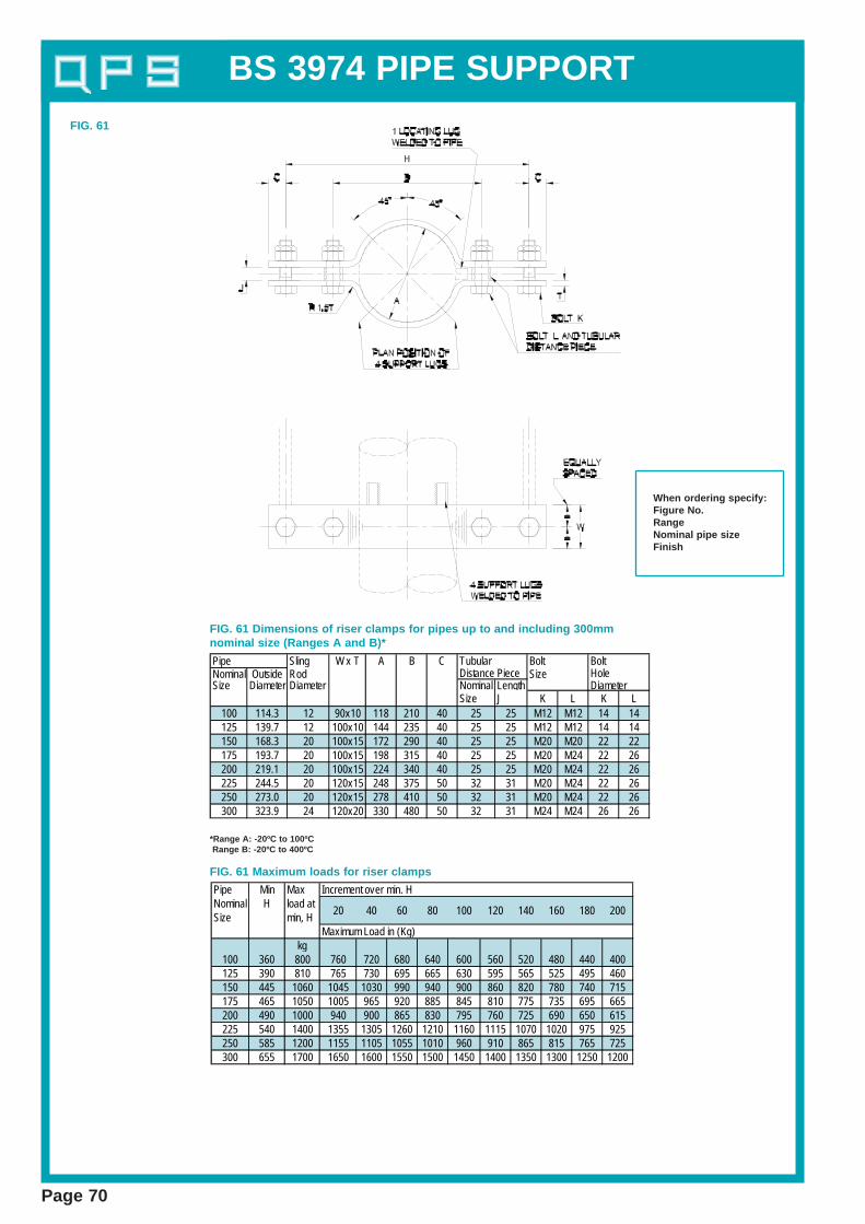
Sling W x T A B CNominal Outside Rod SizeSize Diameter Diameter Nominal Length Diameter
Size J K L K L100 114.3 12 90x10 118 210 40 25 25 M12 M12 14 14125 139.7 12 100x10 144 235 40 25 25 M12 M12 14 14150 168.3 20 100x15 172 290 40 25 25 M20 M20 22 22175 193.7 20 100x15 198 315 40 25 25 M20 M24 22 26200 219.1 20 100x15 224 340 40 25 25 M20 M24 22 26225 244.5 20 120x15 248 375 50 32 31 M20 M24 22 26250 273.0 20 120x15 278 410 50 32 31 M20 M24 22 26300 323.9 24 120x20 330 480 50 32 31 M24 M24 26 26
BoltHole
Pipe TubularDistance Piece
Bolt
Pipe Min Max Increment over min. HNominal H load atSize min, H
Maximum Load in (Kg)kg
100 360 800 760 720 680 640 600 560 520 480 440 400125 390 810 765 730 695 665 630 595 565 525 495 460150 445 1060 1045 1030 990 940 900 860 820 780 740 715175 465 1050 1005 965 920 885 845 810 775 735 695 665200 490 1000 940 900 865 830 795 760 725 690 650 615225 540 1400 1355 1305 1260 1210 1160 1115 1070 1020 975 925250 585 1200 1155 1105 1055 1010 960 910 865 815 765 725300 655 1700 1650 1600 1550 1500 1450 1400 1350 1300 1250 1200
20 40 60 80 180 200100 120 140 160
FIG. 61
FIG. 61 Dimensions of riser clamps for pipes up to and including 300mmnominal size (Ranges A and B)*
FIG. 61 Maximum loads for riser clamps
When ordering specify:Figure No.RangeNominal pipe sizeFinish
*Range A: -20ºC to 100ºCRange B: -20ºC to 400ºC

BS 3974 PIPE SUPPORT
Page 71
Pipe Sling W X T A B C Tubular Bolt Bolt BoltNominal Outside Rod Distance Piece Size Hole HoleSize Diameter Diameter Nominal Length Diameter Centres
SizeP J K L K L G
250 356.6 24 150*20 362 510 50 32 35 M24 M24 26 26 76400 406.4 24 150*20 412 575 50 32 35 M24 M24 26 26 75450 457 30 150*25 454 650 50 32 35 M30 M24 32 26 75500 508 30 180*25 516 705 50 32 35 M30 M24 32 26 100550 559 30 180*25 586 795 50 32 35 M30 M24 32 26 100600 610 30 200*25 616 805 50 32 41 M30 M30 32 32 100
FIG. 62
FIG. 62 Dimensions of riser clamps for pipes over 300mm nominal size (ranges A and B)*
*Range A: -20ºC to 100ºCRange B: -20ºC to 400ºC
Pipe Min Max Increment ov er Min HNominal H Load 20 40 60 80 100 120 140 160 180 200 220 240Size Kg Max imum loads in (Kg)
250 660 2225 2180 2132 2080 2030 1972 1920 1870 1820 1760 1710 1660 1600400 756 2000 1950 1900 1840 1780 1725 1670 1615 1570 1500 1440 1390 1320450 825 2700 2660 2610 2560 2510 2460 2405 2380 2310 2280 2210 2160 2100500 910 3000 2960 2915 2860 2615 2780 2715 2660 2615 2560 2515 2460 2400550 935 2800 2760 2710 2660 2610 2580 2516 2480 2415 2380 2210 2280 2200600 985 3200 3160 3115 3060 3010 2860 2910 2880 2815 2760 2710 2660 2600
FIG. 62 Maximum loads for riser clamps
BS 3974 PIPE SUPPORT
Page 72
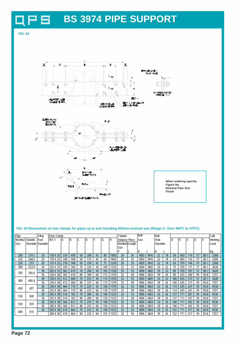
Pipe Sling Riser Clamp Tubular Bolt Bolt SafeNominal Outside Rod W X T A B C D F G H Distance Piece Size Hole O R S U V WorkingSize Diameter Diameter Nominal Length Diameter Load
SizeP J K L K L Kg
200 219.1 20 130 X 25 224 458 50 200 42 85 1085 20 35 M20 M16 22 18 50 483 119 57 38.1 2268225 244.5 20 130 X 25 248 508 50 175 42 65 1065 20 35 M20 M16 22 18 63 483 132 57 38.1 2268250 273 20 155 X 25 278 508 50 250 42 75 1220 20 35 M20 M16 22 18 63 559 146 57 38.1 2268300 323.9 30 205 X 25 330 560 70 226 50 100 1220 25 53 M30 M20 33 22 75 559 171 57 38.1 3628
30 205 X 25 362 610 70 200 50 105 1220 25 53 M30 M20 33 22 89 559 187 57 38.1 362836 230 X 38 362 610 80 280 60 115 1370 32 58 M36 M24 39 26 89 635 200 95 50.8 725730 230 X 25 412 660 70 225 50 115 1370 25 53 M30 M20 33 22 100 635 213 57 38.1 362836 230 X 38 412 660 80 225 60 115 1370 32 58 M36 M24 39 26 100 635 213 95 50.8 725730 230 X 38 464 710 70 225 50 100 1370 32 53 M36 M24 33 26 114 635 241 95 50.8 453636 255 X 38 464 710 80 225 60 130 1370 32 58 M36 M24 39 26 114 635 241 95 50.8 725730 205 X 38 516 762 70 280 50 100 1525 32 53 M30 M24 33 26 127 711 267 95 50.8 453636 255 X 38 516 762 80 280 60 130 1525 32 58 M36 M24 39 26 127 711 267 95 50.8 725730 205 X 38 566 812 70 255 50 100 1525 32 53 M30 M24 33 26 140 711 292 95 50.8 453636 280 X 38 566 812 80 255 60 156 1525 32 58 M36 M24 39 26 140 711 292 95 50.8 725730 205 X 38 618 864 70 225 50 100 1525 32 53 M30 M24 33 26 152 711 317 95 50.8 4536
280 X 38 618 864 80 225 60 155 1525 32 58 M36 M24 39 26 152 711 317 95 50.8 7257
350 356.6
400 406.4
450 457
550 508
550 559
600 610
FIG. 63 Dimensions of riser clamps for pipes up to and including 600mm nominal size (Range C: Over 400ºC to 470ºC)
When ordering specify:Figure No.Nominal Pipe SizeFinish
FIG. 63

BS 3974 PIPE SUPPORT
Page 73
Pipe Sling U-Plate Yoke Safe WorkingNominal Outside Rod Sub-Ranges Hanger Plate End Plate LoadSize Diameter Diameter D1 D2&D3 A B C D E F G H K L x M x T2 D1 and D3
W x T1 W x T1 D2kg kg
200 219.1 24 80x12 100x20 112 470 224 184 40 30 36 50 26 152x152x15 1800 1500225 244.5 24 110x12 100x20 124 480 248 196 40 30 36 50 26 152x152x15 1800 1500250 273 24 110x12 100x25 138 490 276 210 40 30 36 50 26 152x152x15 1800 1500300 323.9 30 100x20 120x25 165 515 330 237 40 35 45 65 33 152x152x15 2700 2260
30 100x20 120x25 181 530 362 253 40 35 45 65 33 152x152x15 2700 226042 140x25 100x40 181 530 362 253 40 50 63 90 45 152x152x20 5900 495030 110x20 140x25 206 560 412 278 50 35 45 65 33 152x152x15 2700 226042 140x25 130x40 206 560 412 278 50 50 63 90 45 152x152x20 5900 495030 100x25 140x30 232 635 464 304 40 35 45 65 33 152x152x20 3600 302042 120x30 140x40 232 635 464 304 40 50 63 90 45 152x152x20 5900 495030 120x25 160x30 258 660 516 330 60 35 45 65 33 154x161x20 3600 302042 130x30 160x40 258 660 516 330 60 50 63 90 45 154x161x20 5900 495030 130x25 180x30 283 685 566 355 70 35 45 65 33 154x161x20 3600 302042 150x30 160x40 283 685 566 355 70 50 63 90 45 154x161x20 5900 495030 140x25 200x30 309 710 618 381 75 35 45 65 33 154x161x20 3600 302042 160x30 200x40 309 710 618 381 75 50 63 90 45 154x161x20 5900 4950
500
450
400
350
559
610600
550
355.6
406.4
457
508
FIG.93 Dimensions of alloy steel U-Straps for steel pipes (Range D:-20ºC to 570ºC)All dimensions are in millimetres.
Material - Carbon SteelWhen ordering specify:Figure No.Nominal Pipe SizeFinish
NOTE 1. This support is suitable only for nominally horizontal sections of pipe lines. When using this type of support consider ation shall be given toproblems related to possible in-service damage to the pipe thermal insulation in the vicinity of the support.NOTE 2. Range D1 gives dimensions for pipe clips using BS 1501: 620 grade 27B (1% Cr , ½% Mo) material for use for maximum temperature of 510ºC.
Ranges D2 and D3 give respectively , dimensions for pipe clips using BS 1501 : 620 grade 27B (1% Cr , ½% Mo) material for use for maximumtemperature of 540ºC and BS 1501: 622 grade 31B (2¼ % Cr , 1% Mo) material for use up to 570ºC.
NOTE 3. Asbestos free tape or millboard may be placed between the pipe and the U-Strap. In such cases, the dimensions of the U- Strap shall beadjusted to ensure that it does not tighten on to the pipe.
FIG. 93
BS 3974 PIPE SUPPORT
Page 74
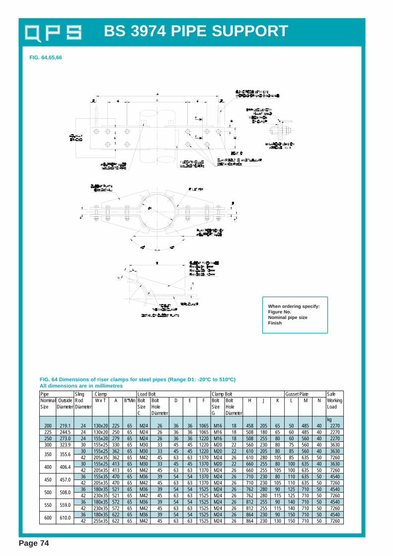
Pipe Sling Clamp Load Bolt Clamp Bolt Gusset Plate SafeNominal Outside Rod W x T A B*Min Bolt Bolt D E F Bolt Bolt H J K L M N WorkingSize Diameter Diameter Size Hole Size Hole Load
C Diameter G Diameterkg
200 219.1 24 130x20 225 65 M24 26 36 36 1065 M16 18 458 205 65 50 485 40 2270225 244.5 24 130x20 250 65 M24 26 36 36 1065 M16 18 508 180 65 60 485 40 2270250 273.0 24 155x20 279 65 M24 26 36 36 1220 M16 18 508 255 80 60 560 40 2270300 323.9 30 155x25 330 65 M30 33 45 45 1220 M20 22 560 230 80 75 560 40 3630
30 155x25 362 65 M30 33 45 45 1220 M20 22 610 205 80 85 560 40 363042 205x35 362 65 M42 45 63 63 1370 M24 26 610 280 105 85 635 50 726030 155x25 413 65 M30 33 45 45 1370 M20 22 660 255 80 100 635 40 363042 205x35 413 65 M42 45 63 63 1370 M24 26 660 255 105 100 635 50 726036 155x35 470 65 M36 39 54 54 1370 M24 26 710 230 80 110 635 50 454042 205x35 470 65 M42 45 63 63 1370 M24 26 710 230 105 110 635 50 726036 180x35 521 65 M36 39 54 54 1525 M24 26 762 280 90 125 710 50 454042 230x35 521 65 M42 45 63 63 1525 M24 26 762 280 115 125 710 50 726036 180x35 572 65 M36 39 54 54 1525 M24 26 812 255 90 140 710 50 454042 230x35 572 65 M42 45 63 63 1525 M24 26 812 255 115 140 710 50 726036 180x35 622 65 M36 39 54 54 1525 M24 26 864 230 90 150 710 50 454042 255x35 622 65 M42 45 63 63 1525 M24 26 864 230 130 150 710 50 7260
550 559.0
600 610.0
450 457.0
500 508.0
350 355.6
400 406.4
FIG. 64 Dimensions of riser clamps for steel pipes (Range D1: -20ºC to 510ºC)All dimensions are in millimetres
FIG. 64,65,66
When ordering specify:Figure No.Nominal pipe sizeFinish
BS 3974 PIPE SUPPORT
Page 75
Pipe Sling Clamp Load Bolt Clamp Bolt Gusset Plate SafeNominal Outside rod W x T A B*Min Bolt Bolt D E F Bolt Bolt H J K L M N working
Size Diameter Diameter Size hole size hole loadC diameter G diameter
kg200 219.1 24 155x25 225 65 M24 26 36 36 1065 M20 22 458 205 80 50 485 40 2270225 244.5 24 155x25 250 65 M24 26 36 36 1065 M20 22 508 180 80 60 485 40 2270250 273.0 24 155x25 279 65 M24 26 36 36 1220 M20 22 508 255 80 60 560 40 2270300 323.9 30 180x35 330 65 M30 33 45 45 1220 M24 26 560 230 90 75 560 40 3630
30 180x35 362 65 M30 33 45 45 1220 M24 26 610 205 90 85 560 40 363042 205x45 362 65 M42 45 63 63 1370 M33 36 610 280 105 85 635 50 726030 205x35 413 65 M30 33 45 45 1370 M24 26 660 255 105 100 635 40 363042 230x45 413 65 M42 45 63 63 1370 M33 36 660 255 115 100 635 50 726036 180x45 470 65 M36 39 54 54 1370 M33 36 710 230 90 110 635 50 454042 230x45 470 65 M42 45 63 63 1370 M33 36 710 230 115 110 635 50 726036 180x45 521 65 M36 39 54 54 1525 M33 36 762 280 90 125 710 50 454042 255x45 521 65 M42 45 63 63 1525 M33 36 762 280 130 125 710 50 726036 180x45 572 65 M36 39 54 54 1525 M33 36 812 255 90 140 710 50 454042 255x45 572 65 M42 45 63 63 1525 M33 36 812 255 130 140 710 50 726036 180x45 622 65 M36 39 54 54 1525 M33 36 864 230 90 150 710 50 454042 255x45 622 65 M42 45 63 63 1525 M33 36 864 230 130 150 710 50 7260
350 355.6
400 406.4
450 457.0
500 508.0
550 559.0
600 610.0
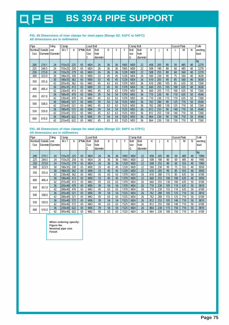
FIG. 65 Dimensions of riser clamps for steel pipes (Range D2: 510ºC to 540ºC)All dimensions are in millimetres
Pipe Sling Clamp Load Bolt Clamp Bolt Gusset Plate SafeNominal Outside rod W x T A B*Min Bolt Bolt D E F Bolt Bolt H J K L M N working
Size Diameter Diameter Size hole size hole loadC diameter G diameter
kg200 219.1 24 155x25 225 65 M24 26 36 36 1065 M20 22 458 205 80 50 485 40 1900225 244.5 24 155x25 250 65 M24 26 36 36 1065 M20 22 508 180 80 60 485 40 1900250 273.0 24 155x25 279 65 M24 26 36 36 1220 M20 22 508 255 80 60 555 40 1900300 323.9 30 180x35 330 65 M30 33 45 45 1220 M20 22 560 230 90 75 555 40 3050
30 180x35 362 65 M30 33 45 45 1220 M20 22 610 205 90 85 555 40 305042 230x40 362 65 M42 45 63 63 1370 M24 26 610 280 115 85 635 50 610030 180x40 413 65 M30 33 45 45 1370 M20 22 660 255 100 100 635 40 305042 255x40 413 65 M42 45 63 63 1370 M24 26 660 255 130 100 635 50 610036 205x40 470 65 M36 39 54 54 1370 M24 26 710 230 105 110 635 50 381042 280x40 470 65 M42 45 63 63 1370 M24 26 710 230 155 110 635 50 610036 205x40 521 65 M36 39 54 54 1525 M24 26 762 280 105 125 710 50 381042 280x40 521 65 M42 45 63 63 1525 M24 26 762 280 155 125 710 50 610036 205x40 572 65 M36 39 54 54 1525 M24 26 812 255 105 140 710 50 381042 305x40 572 65 M42 45 63 63 1525 M24 26 812 255 180 140 710 50 610036 230x40 622 65 M36 39 54 54 1525 M24 26 864 230 115 150 710 50 381042 305x40 622 65 M42 45 63 63 1525 M24 26 864 230 180 150 710 50 6100
350 355.6
400 406.4
450 457.0
500 508.0
550 559.0
600 610.0
FIG. 66 Dimensions of riser clamps for steel pipes (Range D2: 540ºC to 570ºC)All dimensions are in millimetres
When ordering specify:Figure No.Nominal pipe sizeFinish

BS 3974 PIPE SUPPORT
Page 76
Nom pipe Pipe A N M K SSize o.d. dia max.15 21.3 8 40 45 25 1020 26.9 8 45 55 30 1025 33.7 8 50 60 30 1032 42.4 8 60 70 30 1040 48.3 10 65 85 40 1650 60.3 10 80 100 40 1665 76.1 12 95 120 50 1980 88.9 16 110 140 55 19
100 114.3 16 140 165 55 19125 139.7 16 165 190 55 19150 138.3 20 195 225 65 19175 193.7 20 220 250 65 19200 219.1 20 250 275 65 19225 244.5 20 275 300 65 19250 273.0 20 305 335 75 22300 323.9 20 355 385 75 22350 355.6 24 390 425 80 22400 406.4 24 440 475 80 22450 457.0 24 495 525 80 22500 508.0 24 545 575 80 22550 559.0 24 595 625 80 22600 610.0 24 645 675 80 22
80 98 16 120 150 55 19*100 118 16 140 165 55 19*150 170 20 195 225 65 19*200 222 20 250 275 65 19*250 274 20 305 335 75 22*300 326 20 355 385 75 22350 378 24 410 450 80 22400 429 24 465 500 80 22450 480 24 520 550 80 22500 532 24 570 600 80 22600 635 24 670 700 80 22
FIG. 68 Cast Iron Pipes
Dimensions of U-Bolts (not to grip pipe)All dimensions are in millimetres
FIG. 67/68
Material - Carbon SteelWhen ordering specify:Figure No.Nominal pipe sizeFinish
*These U-bolts are identical with the equivalent sizes for steel pipe.

BS 3974 PIPE SUPPORT
Page 77
Nom pipe Pipe A N M K SSize O/D Dia Max15 21.3 8 30 50 25 720 26.9 8 35 60 25 1025 33.7 8 45 65 25 1032 42.4 8 55 75 25 1040 48.3 10 60 90 35 1650 60.3 10 75 100 35 1665 76.1 12 90 130 45 1980 88.9 16 105 150 50 19
100 114.3 16 135 175 50 19125 139.7 16 160 200 50 19150 168.3 20 190 235 55 19175 193.7 20 215 260 55 19200 219.1 20 245 295 55 19225 244.5 20 270 310 55 22250 273.0 20 300 350 60 22300 323.9 20 350 400 60 22350 355.6 24 385 440 65 22400 406.4 24 435 500 65 22450 457.0 24 485 540 70 22500 508.0 24 540 600 70 22550 559.0 24 590 650 70 22600 610.0 24 640 700 70 22
80 98 16 115 160 50 19*100 118 16 135 175 50 19*150 170 20 190 235 55 19*200 222 20 245 295 55 19*250 274 20 300 350 60 22*300 326 20 350 400 60 22350 378 24 405 460 65 22400 429 24 455 520 65 22450 482 24 505 560 70 22500 532 24 560 620 70 22600 635 24 660 720 70 22
Dimensions of U-Bolts (to grip pipe)All dimensions are in millimetres
FIG. 69 Steel Pipes
FIG. 70 Cast Iron Pipes
*These U-bolts are identical with the equivalent sizes for steel pipe.
FIG. 69/70
Material - Carbon Steel.When ordering specify:Figure NoNominal Pipe SizeFinish

BS 3974 PIPE SUPPORT
Page 78
Associated Safe d D W S e P Q nSling Rod Working
Dia Loadkg
8 230 6.3 10 9.5 22 19 25 45 M610 36012 53016 1010 12.7 16 22 48 32 51 97 M1220 1580 16 20 25 57 38 60 120 M1624 2280 19 24 32 70 44 73 133 M2030 3650 25 30 38 92 57 91 180 M2436 5340 32 36 48 114 70 115 225 M3042 7400 38 42 60 140 89 139 271 M36
25 38 76 M109.5 12 16 35
NOTE: The safe working load specified is based upon the safe working load ofassociated sling rods. The actual safe working loads for shackles complyingwith BS 3032 are higher than those given in the table.
FIG. 79 Dimensions of Dee shackles
Material - Carbon SteelWhen ordering specify:Figure No.Sling rod diameterFinish
FIG. 79
Nominal Sling Load Safe Pipe Pipe Rod C or A R B T G H Bolt Load WorkingSize O/D Dia Hole Bolt Loadmm mm mm mm mm mm mm mm mm mm mm kgf15 21.3 8 See 12 20 3 17 70 11 M8 7020 26.9 8 Fig 80 14 20 3 17 75 11 M8 7025 33.7 8 82 & 17 20 3 17 75 11 M8 7032 42.4 8 83 22 20 3 17 80 11 M8 70
FIG. 92 One piece strap, Range A: -20ºC to 100ºC
FIG. 92 Dimensions of one piece strap (with screwed machined,forged and hot formed eye) for uninsualted steel pipe.
Material - Carbon SteelWhen ordering specify:Figure No.Sling rod diameterFinish

BS 3974 PIPE SUPPORT
Page 79
FIG. 71 OVERSTRAP
Nom SteelPipe Pipe Size Hole BoltSize O/D A B WxT C R E Dia15 21.3 53 91 35x5 10 11.5 12 1020 26.9 55 93 35x5 13 14 12 1025 33.7 57 95 35x5 16 18 12 1032 42.4 64 102 35x8 20 22 15 1240 48.3 79 117 35x8 23 25 15 1250 60.3 81 119 35x8 29 31 15 1265 76.1 89 127 45x10 36 40 19 1680 88.9 99 137 45x10 43 46 19 16
100 114.3 108 146 45x10 55 59 19 16125 139.7 119 160 60x10 68 72 24 20150 168.3 136 174 60x10 82 86 24 20175 193.7 155 195 55x15 95 99 24 20200 219.1 170 210 55x15 107 112 24 20
Sling Material Hole Bolt or SafeRod size A C D Dia rod WorkingDia BxT E Dia Load (kg)8 50x6 75 40 50 14 12 230
10 50x6 75 40 50 14 12 36012 50x6 75 40 50 18 16 55016 75x10 85 60 55 22 20 101020 75x12 85 70 55 27 24 158024 100x12 115 75 80 33 30 2280
1. Beam welding attachmentsTwo types of beam welding attachments are specified:Type 1: Inverted U-shape attachmentType 2: U shaped attachment
2. Interchangeability . These attachments are interchangeable ifsupplied with all three holes drilled, as given in table 2.
FIG. 72 BEAM WELDING ATTACHMENT
All dimensions in millimetres
BS 3974 PIPE SUPPORT
Page 80
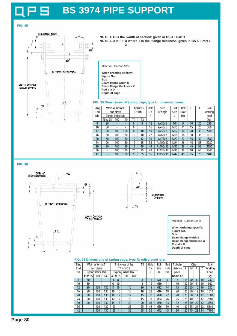
FIG. 95
Sling Hole Size Bolt Bolt C E SafeRod Dia of Angle Size Hole workingDia F D Dia load
45 to 65 100 140 T1 T2 (kg)8 80 - - 6 8 12 Ax30x5 M8 9 10 20 230
10 80 - - 6 - 16 Ax40x6 M10 11 15 25 36012 80 100 130 8 10 18 Ax50x8 M12 14 20 30 53016 80 100 130 10 10 22 Ax65x8 M16 18 30 35 101020 80 100 130 10 12 30 Ax75x8 M20 22 35 40 158024 90 100 130 12 15 33 Ax100x12 M24 26 45 55 228030 90 100 130 15 20 43 Ax100x12 M30 33 45 55 365036 - 100 130 20 25 48 Ax125x12 M36 39 60 65 534042 - 100 130 25 35 56 Ax150x15 M42 45 75 75 7400
Width W for flat Tand cleats
Spring Inside Dia
ThicknessOf flats
NOTE 1. B is the ‘width of section’ given in BS 4 : Part 1NOTE 2. X = T + D where T is the ‘flange thickness’ given in BS 4 : Part 1
2
Material - Carbon Steel
When ordering specify:Figure No.SizeBeam flange width BBeam flange thickness XRod dia DDepth of cage
FIG. 95 Dimensions of spring cage, type U: universal beam
FIG. 96
Sling T3 Hole Bolt Bolt Tubular SafeRod Dia Size Hole distance L M X Z WorkingDia F D Dia piece. Load
45 to 65 100 140 45 to 65 100 140 Nom.Size (kg)8 80 - - 6 8 8 12 M8 9 8 15 20 8 10 230
10 80 - - 6 10 8 16 M10 11 10 20 20 9 10 36012 80 100 130 8 10 10 18 M12 14 15 20 25 10 10 53016 80 100 130 10 10 10 22 M16 18 20 20 30 12 10 101020 80 100 130 10 12 15 30 M20 22 20 25 30 14 12 158024 90 100 130 12 12 15 33 M24 26 25 25 40 18 12 228030 90 100 130 15 15 20 43 M30 33 32 25 50 20 12 365036 - 100 130 20 - 25 48 M36 39 40 30 65 24 12 534042 - 100 130 25 - 25 56 M42 45 50 20 75 28 14 7400
15202535
-101012
Spring Inside Dia Spring Inside Dia
Cleat
-
Width W for flat T Thickness of flatsand cleats T1 and T2
FIG. 96 Dimensions of spring cage, type R: rolled steel joist
Material - Carbon Steel
When ordering specify:Figure No.SizeBeam flange width BBeam flange thickness XRod dia DDepth of cage

BS 3974 PIPE SUPPORT
Page 81
FIG. 97
Sling Width Size Hole Bolt Bolt SafeRod for flat of angle diameter Size hole workingDia T1 F D Dia load
T1 T2 C E H Y (kg)8 35 8 8 Ax30x5 10 20 165 50 12 M8 9 230
10 35 8 8 Ax40x6 15 25 170 50 16 M10 11 36012 45 8 8 Ax50x8 20 30 170 55 18 M12 14 53016 45 10 10 Ax65x8 30 35 180 70 22 M16 18 101020 60 15 10 Ax75x8 35 40 200 90 30 M20 22 158024 80 15 10 Ax100x12 45 55 210 95 33 M24 26 228030 90 15 15 Ax100x12 45 55 240 115 43 M30 33 365036 100 20 20 Ax125x12 60 65 275 140 48 M36 39 534042 130 25 25 Ax150x15 75 75 305 165 56 M42 45 7400
Thicknessof flats
Dimensions
NOTE 1. B is the ‘width of section’ given in BS 4 : Part 1NOTE 2. X = T + D where T is the ‘flange thickness’ given in BS 4 : Part 1
2
Material - Carbon Steel
When ordering specify:Figure No.SizeBeam flange width BBeam flange thickness XRod dia DDepth of cage
FIG. 97 Dimensions of sling rod cage, type U: universal beam
FIG. 98
Sling Width H Y Hole Bolt Bolt Tubular SafeRod for flat Dia Size Hole distance WorkingDia T1 and F D Dia piece Load
cleat T1 T2 T3 Nominal Size L M X Z (kg)8 35 8 8 8 165 50 12 M8 9 8 15 20 8 10 230
10 35 8 8 8 170 50 16 M10 11 10 20 20 9 10 36012 45 8 8 8 170 55 18 M12 14 15 20 25 10 10 53016 45 10 10 10 180 70 22 M16 18 20 20 30 12 10 101020 60 15 10 15 200 90 30 M20 22 20 25 30 14 12 158024 80 15 10 15 210 95 33 M24 26 25 25 40 18 12 228030 90 15 15 15 240 115 43 M30 33 32 25 50 20 12 365036 100 20 20 20 275 140 48 M36 39 40 30 65 24 12 534042 130 25 25 25 305 165 56 M42 45 50 30 75 28 14 7400
CleatThicknessof flats
FIG. 98 Dimensions of sling rod cage, type R: rolled steel joist
Material - Carbon Steel
When ordering specify:Figure No.SizeBeam flange width BBeam flange thickness XRod dia DDepth of cage

BS 3974 PIPE SUPPORT
Page 82
HOOK BOLT (TO GRIP)
FIG. 99
Nom Pipe Pipe A N M K SSize O/D Dia max80 98 16 115 160 50 19
*100 116 16 135 175 50 19*150 170 20 190 235 55 19*200 222 20 245 295 55 19*250 274 20 300 350 60 22*300 326 20 350 400 60 22350 378 24 405 460 65 22400 429 24 455 520 65 22450 480 24 505 560 70 22500 532 24 560 620 70 22600 635 24 660 720 70 22
Nom Pipe Pipe A N M K SSize O/D Dia max15 21.3 8 30 50 25 720 26.9 8 35 60 25 1025 33.7 8 45 65 25 1032 42.4 8 55 75 25 1040 48.3 10 60 90 35 1650 60.3 10 75 100 35 1665 76.1 12 90 130 45 1980 88.9 16 105 150 50 19
100 114.3 16 135 175 50 19125 139.7 16 160 200 50 19150 168.3 20 190 235 55 19175 193.7 20 215 260 55 19200 219.1 20 245 295 55 19225 244.5 20 270 310 55 19250 273.0 20 300 350 60 22300 323.9 20 350 400 60 22350 355.6 24 385 440 65 22400 406.4 24 435 500 65 22450 457.0 24 485 540 70 22500 508.0 24 540 600 70 22550 559.0 24 590 650 70 22600 610.0 24 640 700 70 22
HOOK BOLT (TO GRIP)Fig. 99 Steel pipes 15 - 600nom pipe size
Fig. 99 Cast iron pipes 80 - 600 nom pipe size
When ordering specify:Figure No.Nominal Pipe SizeFinish
Material - Carbon SteelComplete with 2 Nuts
A B Strap C R Hole Boltsize diameter Size
Copper/ WxT Ecopper Steelalloy10 10 13 20 12x1.6 4.5 5.5 3.6 M312 12 19 30 12x2.5 5.5 6.5 5.8 M515 15 19 30 12x2.5 7 8 5.8 M516 16 21 30 15x2.5 7.5 8.5 7 M618 18 23 35 15x2.5 8.5 9.5 7 M620 20 23 35 15x2.5 9.5 10.5 7 M622 22 26 40 20x2.5 10.5 11.5 10 M825 25 28 40 20x2.5 12 13 10 M828 28 30 45 20x3 13.5 14.5 10 M830 30 30 45 20x3 14.5 15.5 10 M835 35 40 55 25x4 17 18 12 M1038 38 40 55 25x4 18.5 19.5 12 M1042 42 43 60 25x4 20.5 21.5 12 M10
44.5 - 43 60 25x4 22 23 12 M10- 50 46 60 25x4 24 26 12 M10
54 - 50 70 30x4 26.5 28 15 M1257 - 52 70 30x4 28 30 15 M1257 - 55 70 30x4 33 34 15 M12
Tube OutsideDiameter
HOOKSTRAP
FIG. 100
Copper/copper alloy tube 10-67 O/DSteel tube 10-50 nom. bore
*These U-Bolts are identical with the equivalent sizesfor steel pipe.
Material - Carbon Steel for steel pipeCopper for copper pipe
When ordering specify:Figure No.Nominal Pipe SizeMaterialFinish
BS 3974 PIPE SUPPORT
BoltSize
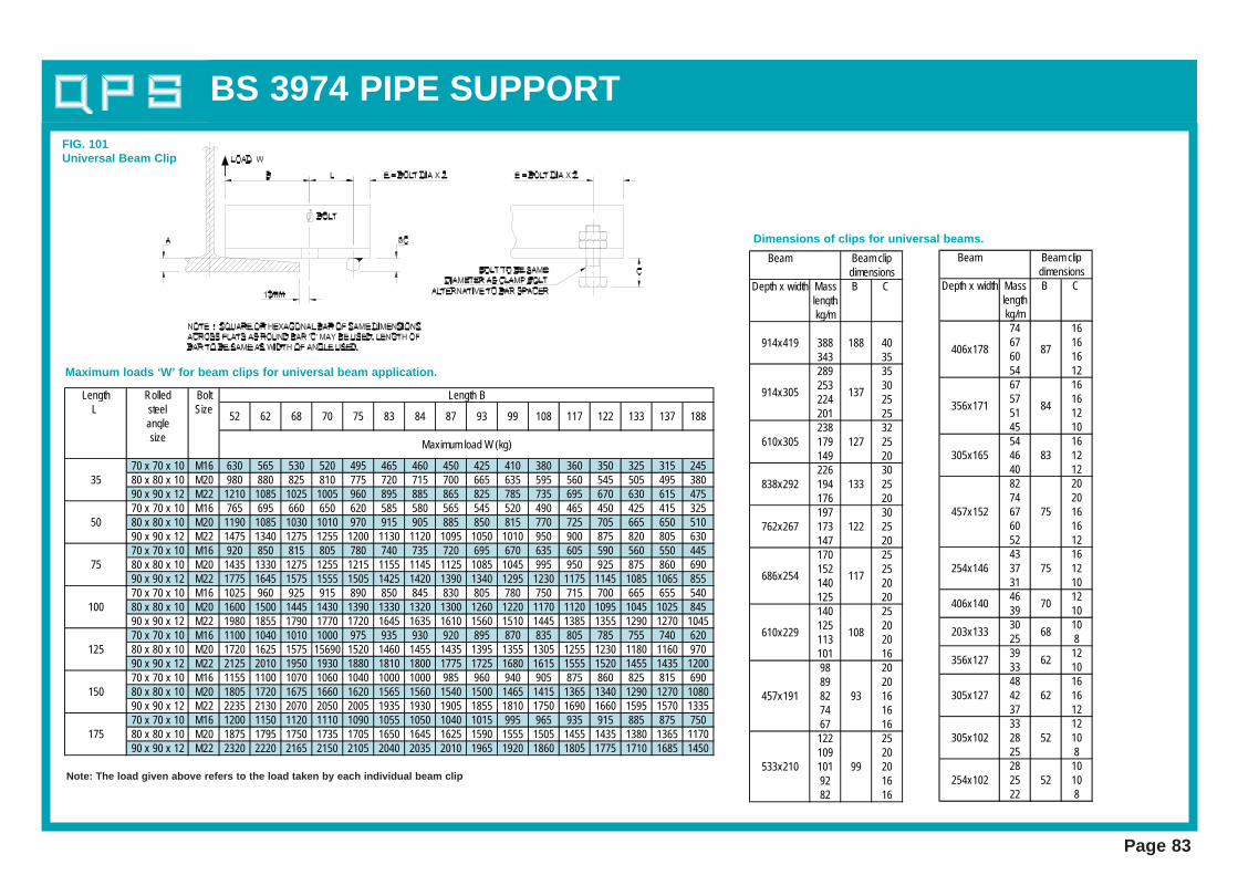
M16 630 565 530 520 495 465 460 450 425 410 380 360 350 325 315 245M20 980 880 825 810 775 720 715 700 665 635 595 560 545 505 495 380M22 1210 1085 1025 1005 960 895 885 865 825 785 735 695 670 630 615 475M16 765 695 660 650 620 585 580 565 545 520 490 465 450 425 415 325M20 1190 1085 1030 1010 970 915 905 885 850 815 770 725 705 665 650 510M22 1475 1340 1275 1255 1200 1130 1120 1095 1050 1010 950 900 875 820 805 630M16 920 850 815 805 780 740 735 720 695 670 635 605 590 560 550 445M20 1435 1330 1275 1255 1215 1155 1145 1125 1085 1045 995 950 925 875 860 690M22 1775 1645 1575 1555 1505 1425 1420 1390 1340 1295 1230 1175 1145 1085 1065 855M16 1025 960 925 915 890 850 845 830 805 780 750 715 700 665 655 540M20 1600 1500 1445 1430 1390 1330 1320 1300 1260 1220 1170 1120 1095 1045 1025 845M22 1980 1855 1790 1770 1720 1645 1635 1610 1560 1510 1445 1385 1355 1290 1270 1045M16 1100 1040 1010 1000 975 935 930 920 895 870 835 805 785 755 740 620M20 1720 1625 1575 15690 1520 1460 1455 1435 1395 1355 1305 1255 1230 1180 1160 970M22 2125 2010 1950 1930 1880 1810 1800 1775 1725 1680 1615 1555 1520 1455 1435 1200M16 1155 1100 1070 1060 1040 1000 1000 985 960 940 905 875 860 825 815 690M20 1805 1720 1675 1660 1620 1565 1560 1540 1500 1465 1415 1365 1340 1290 1270 1080M22 2235 2130 2070 2050 2005 1935 1930 1905 1855 1810 1750 1690 1660 1595 1570 1335M16 1200 1150 1120 1110 1090 1055 1050 1040 1015 995 965 935 915 885 875 750M20 1875 1795 1750 1735 1705 1650 1645 1625 1590 1555 1505 1455 1435 1380 1365 1170M22 2320 2220 2165 2150 2105 2040 2035 2010 1965 1920 1860 1805 1775 1710 1685 145090 x 90 x 12
80 x 80 x 1090 x 90 x 1270 x 70 x 1080 x 80 x 10
70 x 70 x 1080 x 80 x 1090 x 90 x 1270 x 70 x 10
90 x 90 x 1270 x 70 x 1080 x 80 x 1090 x 90 x 12
80 x 80 x 1090 x 90 x 1270 x 70 x 1080 x 80 x 10
70 x 70 x 1080 x 80 x 1090 x 90 x 1270 x 70 x 10
125
150
175
35
50
75
100
Length B
52 62 68 70 75 83 84 13787 93 99 108
size
117 122 133
LengthL
188
Maximum load W (kg)
Rolledsteelangle
Beam
Depth x width Mass B C lengthkg/m
388 40343 35289 35253 30224 25201 25238 32
610x305 179 127 25149 20226 30
838x292 194 133 25176 20197 30
762x267 173 122 25147 20170 25152 25140 20125 20140 25125 20113 20101 1698 2089 2082 93 1674 1667 16
122 25109 20
533x210 101 99 2092 1682 16
457x191
117686x254
610x229 108
Beam clipdimensions
914x305
914x419 188
137
Beam
Depth x width Mass B C lengthkg/m74 1667 1660 1654 1267 1657 1651 1245 1054 16
305x165 46 83 1240 1282 2074 20
457x152 67 75 1660 1652 1243 16
254x146 37 75 1231 1046 1239 1030 1025 839 1233 1048 16
305x127 42 62 1637 1233 12
305x102 28 52 1025 828 10
254x102 25 52 1022 8
68203x133
356x127 62
84356x171
406x140 70
Beam clipdimensions
87406x178
Dimensions of clips for universal beams.
Maximum loads ‘W’ for beam clips for universal beam application.
Note: The load given above refers to the load taken by each individual beam clip
Page 83
FIG. 101Universal Beam Clip