bs 6297 2007 the design and installation of drainage fields for use in waste water treatment
DESCRIPTION
drainage fieldsTRANSCRIPT

BS 6297:2007
Code of practice for the design and installation of drainage fields for use in wastewater treatmentICS 13.060.30
NO COPYING WITHOUT BSI PERMISSION EXCEPT AS PERMITTED BY COPYRIGHT LAW
BRITISH STANDARD
Licensed copy:PONTYPRIDD COLLEGE, 05/01/2008, Uncontrolled Copy, © BSI

Publishing and copyright informationThe BSI copyright notice displayed in this document indicates when the document was last issued.
© BSI 2007
ISBN 978 0 580 60756 1
The following BSI references relate to the work on this standard:Committee reference B/505Draft for comment 07/30138205/DC
Publication historyFirst published April 1983Second edition, December 2007
Amendments issued since publication
Amd. no. Date Text affected
BS 6297:2007
Licensed copy:PONTYPRIDD COLLEGE, 05/01/2008, Uncontrolled Copy, © BSI

www.bzfxw.com
© BSI 2007 • i
BS 6297:2007
ContentsForeword iii
1 Scope 12 Normative references 13 Terms and definitions 24 Drainage fields 45 Preliminary planning, site investigation and assessment 56 Detailed system design 127 Components 208 Construction of drainage field 229 Maintenance 24
AnnexesAnnex A (informative) Plants as drainage indicators 25Annex B (informative) Regulatory requirements 27Annex C (informative) Alternative disposal methods 29
Bibliography 34
List of figuresFigure 1 – Trial hole 9Figure 2 – Cross-section of typical percolation test hole and trial hole 13Figure 3 – Worked example showing percolation test results and calculation of Vp 13Figure 4 – Cross-section of an infiltration trench, example with three trenches 16Figure 5 – Infiltration trench, alternate layout examples 17Figure 6 – Undulating sites 19Figure 7 – Installation of drainage fields on a sloping site (numbered contour lines) 19Figure 8 – Sloping sites with a critical cross-section 20Figure 9 – Typical sample chamber design 22Figure C.1 – Typical cross-section of an infiltration mound with a pump feed 30Figure C.2 – Typical horizontal flow reed bed treatment system 32Figure C.3 – Typical vertical flow reed bed treatment system 33
List of tablesTable 1 – Required information for site assessment 7Table 2 – Features influencing the location of wastewater treatment equipment, drainage fields for a single dwelling, good practice and guidelines 8Table 3 – Subsoil characterization 10Table 4 – Floor area to linear trench length 14Table A.1 – Plants which indicate poor drainage conditions throughout the year 25Table A.2 – Plants which indicate good drainage conditions throughout the year 26Table A.3 – Other plants that indicate soils with poor drainage qualities 27
Summary of pages
This document comprises a front cover, an inside front cover, pages i to iv, pages 1 to 36, an inside back cover and a back cover.
Licensed copy:PONTYPRIDD COLLEGE, 05/01/2008, Uncontrolled Copy, © BSI

www.bzfxw.com
ii • © BSI 2007 This page deliberately left blank
BS 6297:2007
Licensed copy:PONTYPRIDD COLLEGE, 05/01/2008, Uncontrolled Copy, © BSI

www.bzfxw.com
© BSI 2007 • iii
BS 6297:2007
ForewordPublishing informationThis British Standard was published by BSI and came into effect on 31 December 2007. It was prepared by Technical Committee B/505, Wastewater engineering. A list of organizations represented on this committee can be obtained on request to its secretary.
SupersessionThis British Standard supersedes BS 6297:1983, which is withdrawn.
Relationship with other publicationsThis code of practice encompasses some of the subject matter previously covered by BS 6297:1983 in relation to drainage fields. It is complementary to BS EN 12566, which covers small treatment systems up to 50 population equivalents and BS EN 12255, which covers the design of larger treatment systems.
Much of the text is based on CEN/TR 12566-2:20051) [1], so many of its provisions now have the force of this full national British Standard. BS 6297 would be further amended if the current prCEN/TR 12566-5, dealing with pre-treated effluent filtration systems, is published by CEN.
Information about this documentThis is a full revision of the standard, and introduces the following principal changes.
It provides advice on the treatment and dispersal of partially treated wastewater effluent so as to minimize environmental, amenity or public health problems which could arise from the inappropriate use of non-mains wastewater systems.
It covers applications from single households to small communities, including holiday parks with up to 250 population equivalents (PE).
It gives guidance for those designing and installing drainage fields and infiltration systems for use in wastewater treatment. It includes designs of the most commonly used drainage fields. However, alternative infiltration systems are acceptable for specific locations and specialist advice can be sought where appropriate. It is not intended for the code of practice to inhibit the development and application of suitable new processes, and where alternative options for disposal are being considered, the environmental regulator can be consulted to ensure suitability.
The long-term performance of these systems will be dependent on appropriate use and the level of maintenance carried out on upstream treatment equipment.
Use of this documentAs a code of practice, this British Standard takes the form of guidance and recommendations. It should not be quoted as if it were a specification and particular care should be taken to ensure that claims of compliance are not misleading.
1) CEN/TR 12566-2:2005 has not been implemented as a British Standard.
Licensed copy:PONTYPRIDD COLLEGE, 05/01/2008, Uncontrolled Copy, © BSI

www.bzfxw.com
BS 6297:2007
iv • © BSI 2007
Any user claiming compliance with this British Standard is expected to be able to justify any course of action that deviates from its recommendations.
Presentational conventionsThe provisions in this standard are presented in roman (i.e. upright) type. Its recommendations are expressed in sentences in which the principal auxiliary verb is “should”.
Commentary, explanation and general informative material is presented in smaller italic type, and does not constitute a normative element.
Contractual and legal considerationsThis publication does not purport to include all the necessary provisions of a contract. Users are responsible for its correct application.
Compliance with a British Standard cannot confer immunity from legal obligations.
Licensed copy:PONTYPRIDD COLLEGE, 05/01/2008, Uncontrolled Copy, © BSI
www.bzfxw.com
© BSI 2007 • 1
BS 6297:2007
1 ScopeThis code of practice gives recommendations and guidance on the design and installation of drainage fields and infiltration systems for use in wastewater treatment. It is applicable to systems for handling discharges from domestic and commercial sources from single households upwards. These sources are typically septic tanks and package treatment plants.
General guidance is given on good design and installation practices. Particular requirements are determined by local conditions. The recommendations are supplemented, as required, by specialist advice.
NOTE Attention is drawn to the environmental regulators Pollution Prevention Guidelines Note 4 [2] and building regulations and standards (see Annex B). These require an adequate system of drainage to carry foul water from appliances within the building to one of the following, listed in order of priority:
• public sewer
• a private sewer communicating with a public sewer
• either a package wastewater treatment plant or septic tank, with a discharge to a properly designed drainage field.
Only where it can be demonstrated that the cost and/or practicability of connection to the public foul sewer is not feasible will alternative options, including use of drainage fields, be considered acceptable.
2 Normative referencesThe following referenced documents are indispensable for the application of this document. For dated references only the edition cited applies. For undated references the latest edition of the referenced document (including any amendments) applies.
BS EN 1085, Waste water treatment – Vocabulary
BS EN 12566-1, Small wastewater treatment systems for up to 50 PT – Part 1: Prefabricated septic tank
BS EN 12566-3, Small wastewater systems for up to 50 PT – Part 3: Package and or site assembled domestic wastewater treatment plants
BS EN 12566-42), Small wastewater systems for up to 50 PT – Part 4: Prefabricated treatment units for septic tanks assembled in situ from prefabricated kits
BS EN ISO 10319, Geotextiles – Wide-width tensile test (ISO 10319:1993)
2) In preparation at time of publication.
Licensed copy:PONTYPRIDD COLLEGE, 05/01/2008, Uncontrolled Copy, © BSI

www.bzfxw.com
BS 6297:2007
2 • © BSI 2007
3 Terms and definitionsFor the purposes of this document, the terms and definitions given in BS EN 1085 and the following apply.
3.1 biological layer biological film (or biomat) which grows on the base of the infiltration system or on top of the filter material when pre-treated effluent infiltrates the subsoil or the filter material
3.2 connection pipe non-perforated pipe used to connect the septic tank to the distribution chamber
3.3 disposal areatotal area of the site where the pre-treated effluent is discharged into the ground using a soil infiltration system
3.4 distribution chamber chamber allowing even gravity distribution of pre-treated effluent via the distribution pipes
3.5 distribution layer layer of the infiltration system composed of granular fill material in which pre-treated effluent is discharged through infiltration pipes
3.6 distribution pipe non-perforated pipe used to connect the distribution chamber to a single infiltration pipe
3.7 dosing chambersmall tank receiving pre-treated effluent and containing a dosing device, which automatically discharges the desired quantity
3.8 drainage fieldsystem of infiltration pipes placed in trenches and arranged so that effluent can be discharged to the ground
NOTE The most common design of drainage field is shallow linear infiltration trench.
3.9 end connectionperforated and non-perforated pipes and fittings that connect the lower ends of any parallel infiltration pipes, to enable airflow between infiltration pipes
NOTE The connecting fittings may incorporate ventilation and access provision.
3.10 filter materialgranular inert material, usually sand, placed beneath the distribution layer, the purpose of which is to provide a degree of infiltration to the pre-treated effluent
3.11 geotextilefabric which is permeable to liquid and air but prevents solid particles from passing through it and is resistant to decomposition
3.12 granular fill materialinert material in which the infiltration pipes are placed in the distribution layer
Licensed copy:PONTYPRIDD COLLEGE, 05/01/2008, Uncontrolled Copy, © BSI

www.bzfxw.com
© BSI 2007 • 3
BS 6297:2007
3.13 infiltrationpercolation of effluent around the point at which it is discharged
3.14 infiltration pipeperforated pipe through which the pre-treated effluent is discharged to the infiltration trench or bed
NOTE Often called a percolation pipe.
3.15 infiltration systemseries of infiltration pipes, placed in either single trenches or one large bed, used to discharge effluent in such a way that it percolates into the disposal area
3.16 infiltration trenchtrench in which a single infiltration pipe is placed and surrounded by fill material and separated from other infiltration trenches by undisturbed soil
3.17 land drainsurface or subsurface channel for the transportation of rain water, used to drain ground and divert the natural flow of surface and subsurface water away from infiltration area
3.18 geotextile membranefabric which is permeable to liquid and air but prevents rough solid particles from passing through it and which is resistant to decomposition
NOTE The hole diameters are approximately 1 mm.
3.19 pre-treated effluent wastewater that has undergone at least primary treatment
3.20 soakawaypermeable area of ground, or buried structure, designed to speed the drainage of clean surface water into the ground
3.21 subsoilunconsolidated material beneath the topsoil and above the bedrock
3.22 topsoilupper layer of soil
3.23 upstream systemseptic tank or secondary wastewater treatment system
3.24 water tablelevel below which the ground is saturated with water
NOTE The water table has seasonal variations.
3.25 trial holepit excavated to establish the ground characteristics and depth of water table and bedrock
3.26 percolation test holepit excavated to establish soil porosity and trench requirements
Licensed copy:PONTYPRIDD COLLEGE, 05/01/2008, Uncontrolled Copy, © BSI
www.bzfxw.com
BS 6297:2007
4 • © BSI 2007
4 Drainage fieldsNOTE Drainage fields are an important component of the wastewater treatment system. They are used extensively in the UK, particularly in conjunction with septic tanks and small wastewater treatment plants. Drainage fields provide additional treatment in the ground as well as ensuring a means of disposal of the effluent.
In advance of the drainage field, a septic tank or treatment plant conforming to BS EN 12566-1, BS EN 12566-43), or BS EN 12566-3 should be installed in accordance with the manufacturer’s instructions.
NOTE The results from the standards type tests demonstrate the capability to meet the regulators’ requirements.
The treatment and dispersal processes that occur within drainage fields take place within trenches in three distinct zones as follows.
• Infiltration zone: this is the top few centimetres of soil below the drainage trench, which is biologically active and contributes to the further treatment of effluent. Through continued use, a biological layer builds up within the pipe and the surrounding trench media and provides further treatment of the effluent.
• Unsaturated zone: this is located below the infiltration zone. This forms the pathway between the infiltration zone and the saturated zone. This area has the potential to provide additional attenuation depending upon its depth and characteristics. It provides a significant pathway for oxygen diffusion to aid further treatment.
• Saturated zone: this is beneath the unsaturated zone. All the voids are filled with ground water. There is further dispersion and dilution of the treated effluent.
Poor design and/or installation of a drainage field in an inappropriate location can lead to public nuisance, cause damage to the environment, and cause harm to human health.
Drainage fields do not operate indefinitely and eventually need to be replaced. When designing wastewater treatment systems, whole-life costing of both plant and drainage field design should be carried out and include provision for the future replacement of the drainage field.
It is essential that regular maintenance of the septic tank or wastewater treatment plant is carried out, and the owner should regularly inspect the entire system and drainage field to ensure continuing satisfactory operation. Well maintained package treatment plants are more likely to extend the life of a drainage field than septic tanks.
Fats, oils and greases should be removed from the wastewater as they can shorten the life of a drainage field if they are not properly isolated or treated.
Traditional soakaways (deep-pit based systems), often filled with bricks and other granular material, should not be used for wastewater effluent disposal as they do not provide sufficient treatment.
3) In preparation at time of publication.
Licensed copy:PONTYPRIDD COLLEGE, 05/01/2008, Uncontrolled Copy, © BSI

www.bzfxw.com
© BSI 2007 • 5
BS 6297:2007
Rainwater or surface water soakaways permit the rapid dispersal of water without any further treatment of pollutants. These are not appropriate for the disposal of wastewater effluent.
Drainage fields should be clearly differentiated from rainwater soakaways.
5 Preliminary planning, site investigation and assessment
5.1 General The effectiveness of a drainage field to treat and disperse effluent is influenced by groundwater levels and soil moisture content. These vary throughout the year and it is important that the site is able to continue to accommodate a discharge of effluent under the range of possible soil conditions.
The site should be carefully evaluated to assess both the environmental risks and the suitability of the proposed treatment system before installation of the drainage field.
A large amount of information and investigation is required to support a proposal for a drainage field. An assessment of the suitability of the site should include the following:
• preliminary planning (see 5.2);
• detailed site investigation to identify suitable drainage field locations, including assessment of site characteristics and environmental risks (see 5.3);
• detailed system design, including percolation testing and determination of trench area and layout (see 5.4 and 6.2).
5.2 Preliminary planningThe regulator requires a risk-based assessment, which considers the volume, location and sensitivity of the site. This might involve the collection of more comprehensive data and include the services of a professional adviser or hydrogeologist to support the proposal. Some sites will be deemed unsuitable and alternative options will need to be agreed with the regulator.
Legislative requirements relating to the proposed sewerage system should be identified as part of the assessment. Contact should be made with the Planning Authority and, where necessary, the environmental regulator in order to determine whether permission, consent or a licence is required for a treatment unit or drainage field in the proposed area.
5.3 Site investigation
5.3.1 Detailed site investigation
A detailed site investigation should be carried out to identify and document all the relevant site details at the location of the proposed drainage field. This is so that all the risks are identified and considered in relation to the scale of the development.
Licensed copy:PONTYPRIDD COLLEGE, 05/01/2008, Uncontrolled Copy, © BSI

www.bzfxw.com
BS 6297:2007
6 • © BSI 2007
The amount of information required within the detailed assessment varies with the nature and volume of the discharge, the ground characteristics and the environmental sensitivity of the site. The site investigation should consider:
• the requirements of the regulatory bodies;
• the presence of any environmental receptor, for example wells, boreholes, springs, or sources of water for human consumption or agricultural uses;
• proximity to other receptors, including habitable buildings and watercourses;
• proximity to any existing drain or sewer;
• site topography and site practicalities;
• the soil characteristics, including soil profile and porosity (see 5.4.1, 5.4.2 and 6.2);
• the composition of the effluent and its rate of discharge into the system;
• the distance to other drainage fields and rainwater soakaways.
Table 1 and Table 2 set out many of the criteria that should be considered. Some or all of this information might be required by the regulatory authorities to support the installation and provide evidence to help assess the level of environmental risk.
5.3.2 Protection of drinking water sourcesSerious and long-term pollution can occur to groundwater from inappropriately installed drainage fields.
The distance can be significantly increased depending upon the size of the discharge, environmental sensitivity and local site characteristics.
There should be a minimum distance of 50 m between the drainage field and a well, spring, borehole or other source of water supply intended for human consumption.
Where site investigations identify sources of groundwater used or intended for human consumption, it is unlikely to be suitable for a drainage field. The environmental regulator should be consulted before undertaking detailed system design and planning.
A number of geological and hydrogeological factors control the risk to groundwater, including the type and depth of soil and distance to the water table. Other environmental factors that should be considered include but are not limited to:
• risk of health hazard or nuisance;
• impacts on wells, boreholes and other water sources used or intended for human consumption;
• amenity or conservation habitat;
• flooding or waterlogging due to unsuitable drainage characteristics;
• nutrient overloading of surface water catchments.
Licensed copy:PONTYPRIDD COLLEGE, 05/01/2008, Uncontrolled Copy, © BSI

www.bzfxw.com
© BSI 2007 • 7
BS 6297:2007
5.3.3 Visual site inspection
The investigation should consider physical features of the site, including the landscape and slope, and note the established vegetation in the area. This can provide useful information as to the overall site suitability, or areas of the site that are likely to be more or less suitable than others.
Table 1 Required information for site assessment
Description Required information User notes
Details of premises Address.Application details (e.g. residential, domestic, commercial, or hotel, public house, factory).Maximum Population Equivalent (PE) served and anticipated maximum volume of effluent generated from the premises.Method of water supply to premises (e.g. mains supply or local abstraction).Details of any special effluent, e.g. hotels with own laundry, care homes with high proportion of dependent residents.
Site map showing Map grid references.Total site or property area.Area available for effluent disposal.Adjacent buildings (existing/proposed).Adjacent roadways. Site boundaries.Site topography.Site elevation (relative to sea level).Location of groundwater sources (wells, springs, etc.) relative to drainage field.Location of underground services.Surface water disposal route(s).Location of adjacent drainage fields or rainwater soakaways.Location of adjacent water courses.Rock outcroppings.Other wastewater discharges.
Soil characteristics Soil drainage characteristics.Topsoil type (descriptions, texture, colour).Subsoil type (descriptions, texture, colour).Presence of impermeable soil layer (e.g. clay).Presence of highly permeable layer (e.g. gravel).Depth of winter frost level, if appropriate.
Bedrock Depth to bedrock (in trial holes). Bedrock characteristics (e.g. impermeable, fissured, permeable).
Ground water conditions
Type of aquifer.Presence of shallow groundwater and estimated depth to seasonally highest water table.Groundwater flow direction (based on observed water levels or derived from topography and surface water features). Wells and boreholes used for abstracting groundwater within the likely range of impact.Ditches, springs, watercourses or other surface drainage features that may be fed by groundwater.
General Vegetation type.Trees or other plants with extensive root systems.
Other
Licensed copy:PONTYPRIDD COLLEGE, 05/01/2008, Uncontrolled Copy, © BSI
www.bzfxw.com
BS 6297:2007
8 • © BSI 2007
5.4 Assessment
5.4.1 Trial hole A trial hole is distinguishable from a percolation test hole used to establish soil porosity and trench requirements.
As part of the detailed investigation, a trial hole (see Figure 1) should be safely excavated (see 8.3.7). The hole should be excavated adjacent to the area where the drainage field is to be installed. Consideration should be given to identifying the maximum seasonal groundwater table level.
A trial hole should be used to identify:
• whether shallow groundwater is present and determine groundwater levels;
• soil profiles with textural descriptions;
• appropriate depth below ground level to perform percolation tests;
• the presence of bedrock and investigate its characteristics.
Table 2 Features influencing the location of wastewater treatment equipment, drainage fields for a single dwelling, good practice and guidelines
Item Good practice
Habitable buildings Position as far away as is practical, consider prevailing wind direction. Recommended minimum: 7 m.
Water course or ditch Building regulations and PPG4 recommend a minimum of 10 m for a drainage field.
Public road or other access road Varies with local and national requirements consult Highway and Building Regulations.
Site boundary No part of the drainage field should be within 2 m of the boundary of the adjoining site.
Trees or other plants with a deep or extensive root systems Advice to be sought from suitable competent person.NOTE This also applies to the cultivation of crops which would inevitably necessitate the use of machinery (even light machinery) likely to disturb the materials installed at a shallow depth.
Topography Landscape features that retain or concentrate subsurface flows such as swales or depressions should be avoided.
Water supply pipes or underground services Other than those required by the infiltration system itself, pipes should not be located within or adjacent to the disposal area.
Access roads, driveways or paved areas Should not be located within the disposal area.
Other drainage fields The proximity of other drainage fields or rainwater soakaways should not compromise the drainage characteristics of the proposed site.
Additional considerations Power supply for mechanical systemsSite securityAccess for desludging, considering local contractor requirementsSpace for future expansion
NOTE Recommended distances are indicative only and may be more stringent depending on local regulatory or policy positions.
Licensed copy:PONTYPRIDD COLLEGE, 05/01/2008, Uncontrolled Copy, © BSI
www.bzfxw.com
© BSI 2007 • 9
BS 6297:2007
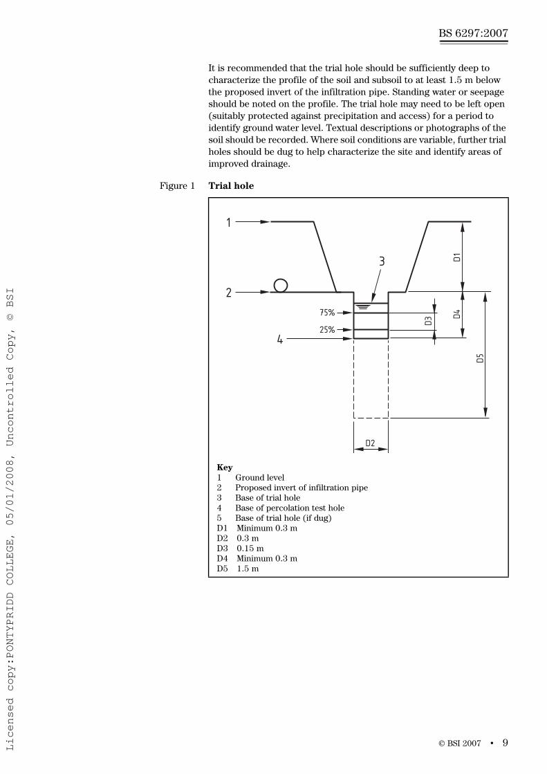
It is recommended that the trial hole should be sufficiently deep to characterize the profile of the soil and subsoil to at least 1.5 m below the proposed invert of the infiltration pipe. Standing water or seepage should be noted on the profile. The trial hole may need to be left open (suitably protected against precipitation and access) for a period to identify ground water level. Textual descriptions or photographs of the soil should be recorded. Where soil conditions are variable, further trial holes should be dug to help characterize the site and identify areas of improved drainage.
Figure 1 Trial hole
Key1 Ground level2 Proposed invert of infiltration pipe3 Base of trial hole4 Base of percolation test hole5 Base of trial hole (if dug)D1 Minimum 0.3 mD2 0.3 mD3 0.15 mD4 Minimum 0.3 mD5 1.5 m
2
1
3
425%
75%
D2
D3
D1
D5
D4
Licensed copy:PONTYPRIDD COLLEGE, 05/01/2008, Uncontrolled Copy, © BSI
www.bzfxw.com
BS 6297:2007
10 • © BSI 2007
5.4.2 Soil characteristics and site geologyRecords and documents will provide useful background information on the classification of the soil in relation to its likely drainage properties and risk to groundwater. Similarly, published information on the soil depth to bedrock and the nature of underlying geology will help place the result from a trial hole in its wider context.
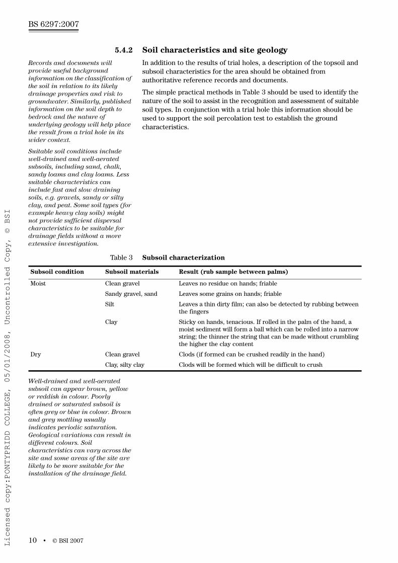
In addition to the results of trial holes, a description of the topsoil and subsoil characteristics for the area should be obtained from authoritative reference records and documents.
The simple practical methods in Table 3 should be used to identify the nature of the soil to assist in the recognition and assessment of suitable soil types. In conjunction with a trial hole this information should be used to support the soil percolation test to establish the ground characteristics.
Suitable soil conditions include well-drained and well-aerated subsoils, including sand, chalk, sandy loams and clay loams. Less suitable characteristics can include fast and slow draining soils, e.g. gravels, sandy or silty clay, and peat. Some soil types (for example heavy clay soils) might not provide sufficient dispersal characteristics to be suitable for drainage fields without a more extensive investigation.
Well-drained and well-aerated subsoil can appear brown, yellow or reddish in colour. Poorly drained or saturated subsoil is often grey or blue in colour. Brown and grey mottling usually indicates periodic saturation. Geological variations can result in different colours. Soil characteristics can vary across the site and some areas of the site are likely to be more suitable for the installation of the drainage field.
Table 3 Subsoil characterization
Subsoil condition Subsoil materials Result (rub sample between palms)
Moist Clean gravel Leaves no residue on hands; friable
Sandy gravel, sand Leaves some grains on hands; friable
Silt Leaves a thin dirty film; can also be detected by rubbing between the fingers
Clay Sticky on hands, tenacious. If rolled in the palm of the hand, a moist sediment will form a ball which can be rolled into a narrow string; the thinner the string that can be made without crumbling the higher the clay content
Dry Clean gravel Clods (if formed can be crushed readily in the hand)
Clay, silty clay Clods will be formed which will be difficult to crush
Licensed copy:PONTYPRIDD COLLEGE, 05/01/2008, Uncontrolled Copy, © BSI

www.bzfxw.com
© BSI 2007 • 11
BS 6297:2007
5.4.3 Water table
The local authority or environmental regulator may be able to help identify sources of information and records of seasonal local groundwater levels. This information can be considered in conjunction with the results of trial holes to achieve the best possible understanding of the groundwater conditions. Examination of the topography and any surrounding water features, such as springs, seepages, wetlands and watercourses, will help to identify the presence of shallow water tables and the likely direction of groundwater flow.
A drainage field should not be installed in a flood plain or in seasonally waterlogged, boggy or frequently wetted areas. Flood plain maps are available from the environmental regulator.
5.4.4 Plants as drainage indicators
The presence of a particular plant can be a useful indicator of the drainage properties of an area. The presence and abundance of several indicator plants from the same group are more reliable than the presence of a single indicator plant.
The presence of indicator plants should not be taken as conclusive evidence that the site is suitable for a drainage system, but they might indicate where any subsequent soil investigations could take place (see Annex A).
5.4.5 Influent parameters
The drainage field system should be designed to accept the total daily flow from the properties. The infiltration systems are intended to receive only domestic wastewater (without any other water, such as rainwater) pre-treated by a septic tank or wastewater treatment system. Systems to treat commercial wastewater (restaurants, hotels, factories, etc.) can require different or more extensive designs and the environmental regulator should be consulted.
Guidance on estimating volumes from domestic and non domestic applications is given in British water code of practice flows and loads [3].
Some properties can have higher than average rates of discharge and this should be considered when estimating daily flow rates. Exceptional equipment includes spa baths, larger than average baths, commercial laundry equipment, and medical equipment, e.g. bedpan washers.
If the effluent contains a high proportion of heated water, or treatment chemicals, then guidance should be sought from the system provider to identify any additional pre-treatment or holding facility necessary to adjust the effluent parameters to make it suitable for wastewater treatment.
5.4.6 Site characteristics
The proximity of other drainage fields and rainwater soakaways should be determined to ensure the ground conditions are suitable to accommodate the total discharge from all of these sources.
Licensed copy:PONTYPRIDD COLLEGE, 05/01/2008, Uncontrolled Copy, © BSI

www.bzfxw.com
BS 6297:2007
12 • © BSI 2007
6 Detailed system design
6.1 Estimating drainage field areaThe following factors should be considered in estimating the total area of the drainage field:
• effluent volume;
• soil suitability (provided by the percolation test, trial holes and soil characteristics);
• availability of land for trench network.
6.2 Percolation test procedure
6.2.1 General
To determine the length and area of infiltration trench required to disperse the effluent, a percolation test should be carried out. Soil porosity can vary across a site and the percolation test should be carried out at the intended location of the proposed drainage field. This test should be avoided in extreme weather conditions, such as drought, frost or heavy rain.
6.2.2 Test method
The percolation test should be carried out as follows.
• Excavate at least two holes 300 mm square to a depth at least 300 mm below the proposed invert level (bottom of pipe) of the infiltration pipe, spacing them along the proposed line of the subsurface irrigation system. While digging the hole, note and record changes in soil characteristics at measured depths and the position of the water table if reached.
• Saturate the local soil by filling each hole with water to a depth of at least 300 mm and allow this to seep away completely.
• If the water drains rapidly (within 10 minutes) the hole should be refilled up to a maximum of 10 times. If the water continues to drain away rapidly the ground is unsuitable.
• If the water has not soaked away within 6 hours the area is not suitable.
• Determine the percolation rate by refilling each hole with water to a depth of at least 300 mm and observe the time in seconds for the water to seep away from 75% full to 25% full (i.e. a depth of 150 mm).
• Divide this time in seconds by 150. This gives the average time in seconds required for the water to drop 1 mm.
• Repeat the test at least three times in each hole in the location of the proposed trench(es).
• Take the average figure from the tests to produce the percolation value Vp (in seconds).
• Obtain the average figure for the percolation value (Vp) by summing all the values and dividing by the number of values used.
Licensed copy:PONTYPRIDD COLLEGE, 05/01/2008, Uncontrolled Copy, © BSI

www.bzfxw.com
© BSI 2007 • 13
BS 6297:2007
• The results from the percolation test should be tabulated as set out in Figure 3. It is advisable to retain this information for the future property owner.
NOTE The cross-section layout of a percolation test can be seenin Figure 2.
Figure 2 Cross-section of typical percolation test hole and trial hole
Key1 Ground level2 Proposed invert of infiltration pipe3 Water level inside test hole4 Base of test holeD1 0.3 mD2 0.3 mD3 1.0 m
Figure 3 Worked example showing percolation test results and calculation of Vp
Hole No.
Test Date
Test No.
Start time
Finish time
Elapsed time Vp(s/mm)
Hours/minutes(h/mins)
Minutes(mins)
Seconds(s)
Seconds divided by 150 mm
1 1 09.30 10.30 1 h 60 3 600 24
2 11.00 11.45 45 min 45 2 700 18
3 12.00 13.12 1 h 12 min 72 4 320 28.8
Average VP for Hole 1 23.6
2 1 09.50 11.00 1 h 10 min 70 4 200 28
2 11.30 13.10 1 h 40 min 100 6 000 40
3 14.00 15.30 1 h 30 min 90 5 400 36
Average VP for Hole 2 34.7
3 1
2
3
Average VP for Hole 3
2
1
3
425%
75%
D2
D3
D1
Licensed copy:PONTYPRIDD COLLEGE, 05/01/2008, Uncontrolled Copy, © BSI

www.bzfxw.com
BS 6297:2007
14 • © BSI 2007
Where Vp results vary widely (50% above or below the average figure), make further tests on a minimum of three different locations in the area of the proposed drainage field.
The minimum value of 15 ensures that untreated effluent cannot percolate too rapidly into the ground, potentially resulting in the pollution of groundwater.
Drainage field disposal should only be used when percolation tests indicate average values of Vp between 15 and 100 and the preliminary assessment of the trial hole tests has been favourable.
Where Vp is above the limit of 100 effective treatment is unlikely to take place in a drainage field as there will be inefficient soakage in this location, which may lead to wastewater ponding on the surface.
If the Vp is between one and 15, or greater than 100, the regulator should be consulted to identify options for disposal.
6.3 Calculating trench area and trench lengthThe layout of the trench network will depend upon the soil porosity and the availability of land.
For domestic premises, the floor area of the drainage field required should be calculated as follows.
for septic tanks
A = required drainage field floor area in square metres (m2).
p = number of people served by the tank (for domestic applications this should be the maximum number of people that could live in the dwelling).
Vp = percolation value.
For effluents which have received secondary treatment, the area should be reduced by 20% as follows.
for package wastewater treatment plants
The floor area “A” should be converted to a linear trench based on the width of the trench
Drainage trench widths should be between 0.3 m to 0.9 m. See examples of conversions for different trench widths in Table 4.
A = p Vp 0.25 × ×
A = p Vp 0.20× ×
Table 4 Floor area to linear trench length
Drainage field floor area (A) m2
Linear trench length (in metres)
0.3 m width trench 0.6 m width trench 0.9 m width trench
20 66 33 22
30 100 50 33
40 133 67 44
50 167 83 56
60 200 100 66
70 233 117 78
80 266 134 88
90 300 150 100
Licensed copy:PONTYPRIDD COLLEGE, 05/01/2008, Uncontrolled Copy, © BSI

www.bzfxw.com
© BSI 2007 • 15
BS 6297:2007
6.4 Trench depthThe following factors should be considered when assessing the trench depth.
• frost cover;
• protection from disturbance;
• depth of the outlet pipe from the tank;
• permeability of the subsoil;
• depth to water table;
• depth to bedrock.
6.5 Effluent distributionOne of the two following methods should be used to distribute effluent into the trench system.
• Gravity flow – Due to the minimal energy requirements, this is the preferred option. It can be used where there is a sufficient fall to the drainage system. Settled wastewater discharges over much of the day at a low flow (trickle).
• Intermittent dosing – This is achieved by a pump that periodically discharges the contents of a dosing chamber through the drainage system. This is used where there is insufficient fall, or where the drainage field is at a remote or higher level.
For gravity flow systems from a small number of houses, the maximum length of a single trench should be no more than 30 m because of the increased risk of poor distribution with longer trenches.
NOTE For pumped or intermittently dosed systems, longer lengths of infiltration pipes may be used.
6.6 Drainage field layoutThe design of drainage field should be based on rows of shallow linear infiltration trenches, joined to form interconnecting loops. Preferred layouts are shown in Figure 4 and Figure 5.
Licensed copy:PONTYPRIDD COLLEGE, 05/01/2008, Uncontrolled Copy, © BSI

www.bzfxw.com
BS 6297:2007
16 • © BSI 2007
Figure 4 Cross-section of an infiltration trench, example with three trenches
KeyABC
123
4567
Longitudinal cross-sectionPlanCross-section
SubsoilDistribution layerInfiltration pipeSand layer, if necessary to level distribution chamber and pipeworkConnection pipeDistribution chamberDistribution pipe
8910
D1D2 D3
D4
W1W2L1
BackfillEnd connection with ventilation and access, if necessaryGeotextile membrane
Total depth u 1.0 mBackfill depth W 0.2 mInfiltration pipe diameter + 0 m to 0.1 m of granular fill material (same as in the distribution layer)Distribution layer thickness beneath infiltration pipe, 0.2 m to 0.3 m
Natural ground width between trenches W 1 mDistribution layer width 0.3 m to 0.9 mDistribution layer length u 30 m
W2
B
B
A A
A-A
B-B
W1
L1
W2
D2
D3
D4
D1
1
3
2
8
10
9
1234
5
6 D2
D3
D4
D1
23476
5 W1
Licensed copy:PONTYPRIDD COLLEGE, 05/01/2008, Uncontrolled Copy, © BSI
www.bzfxw.com
© BSI 2007 • 17
BS 6297:2007
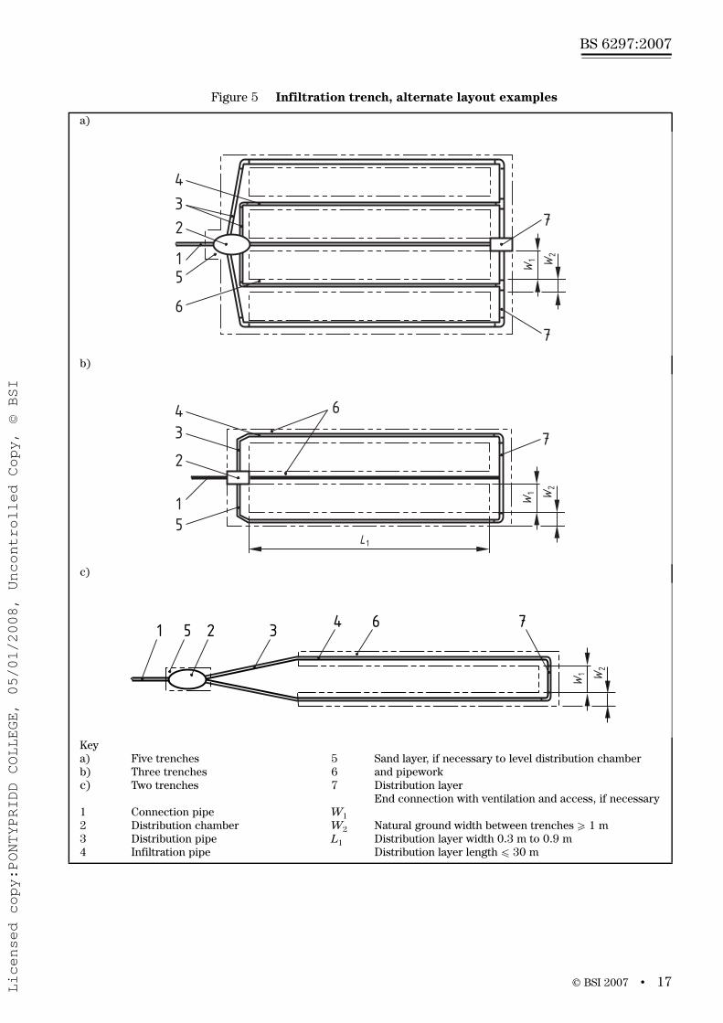
Figure 5 Infiltration trench, alternate layout examples
a)
b)
c)
Keya)b)c)
1234
Five trenchesThree trenchesTwo trenches
Connection pipeDistribution chamberDistribution pipeInfiltration pipe
567
W1W2L1
Sand layer, if necessary to level distribution chamber and pipeworkDistribution layerEnd connection with ventilation and access, if necessary
Natural ground width between trenches W 1 mDistribution layer width 0.3 m to 0.9 mDistribution layer length u 30 m
W1
4
W2
32
15
6
7
7
L1
W1 W
2
643
2
15
7
W1 W
2
643251 7
Licensed copy:PONTYPRIDD COLLEGE, 05/01/2008, Uncontrolled Copy, © BSI
www.bzfxw.com
BS 6297:2007
18 • © BSI 2007
Other drainage field designs are available and could be appropriate for specific sites, considering local environmental and physical parameters. Alternative designs may be acceptable and should be justified by a detailed technical assessment. Examples of other drainage field and infiltration system designs are given in Annex C.
6.7 Other design parametersThe perforated pipes should be laid in trenches with a uniform gradient, not steeper than 1:200. Pipes should be laid at a depth greater than 0.2 m below the surface.
Excavation of trenches or beds should be carried out very carefully in order to avoid disturbing or compacting the surrounding soil. If necessary, the sides and base of the excavation should be raked. Machinery should not traverse the area after the work has been completed.
Excavation should not be carried out when the ground is wet.
Trenches and beds should be covered and back-filled as soon as possible.
Trench sides should be separated by undisturbed areas of ground which are greater than 1 m wide.
All drainage fields should have a margin of 1 m of undisturbed soil from the outer trench; this is considered to be part of the disposal area.
On sloping sites, the infiltration pipes should be installed parallel to the contours of the ground.
The base of the trench should have a minimum of 1.2 m of unsaturated soil present above the determined seasonally highest groundwater level. Where these dimensions cannot be accommodated, alternative arrangements will be required (see Annex C).
Where inflow of surface or ground water could reduce the effectiveness of the drainage field, land drains should be installed to divert water away so as not to prejudice the capacity of the system.
Rainwater or surface water drainage should not be installed in or around the drainage field, as this could prejudice the capacity of the system. Wherever possible the surface water system should discharge away from the drainage field or be diverted around it.
Drainage fields should not contaminate the land drains.
6.8 Dealing with difficult sites and ground conditions
Ground characteristics can vary significantly across a site and sloping sites need particular consideration. On sloping sites, topography and groundwater should be considered
before selecting the location of a drainage field. See examples shown in Figure 6, Figure 7 and Figure 8.
Licensed copy:PONTYPRIDD COLLEGE, 05/01/2008, Uncontrolled Copy, © BSI

www.bzfxw.com
© BSI 2007 • 19
BS 6297:2007
Figure 6 Undulating sites
Key1 Groundwater table2 Groundwater3 Bedrock4–6 locations of drainage field trenchesLocation 4 = goodLocation 5 = good/bestLocation 6 = unsuitable
NOTE The optional selection of infiltration site is based on land topography and groundwater level.
Figure 7 Installation of drainage fields on a sloping site (numbered contour lines)
Key1 PondA Drainage fieldB Drainage field
NOTE Site A is good for a drainage field as it spreads the effluent. Site B is unsuitable as the effluent will not be spread and may create a pond
6
4
5
6
4
32
1
1A
B
605856
54
Licensed copy:PONTYPRIDD COLLEGE, 05/01/2008, Uncontrolled Copy, © BSI

www.bzfxw.com
BS 6297:2007
20 • © BSI 2007
The regulator will require a risk-based assessment which will consider the volume, location and sensitivity of the site. This might involve the collection of more comprehensive data and necessitate the services of a professional adviser or hydrogeologist to support the proposal. Some sites may be deemed unsuitable, so alternative options for the disposal of effluent should be made.
Where site conditions or soil characteristics indicate that a drainage field might not function adequately at the proposed location, alternative areas of the site should be identified and the site assessment and the percolation tests repeated.
The environmental regulator or local authority building control officer should be contacted where:
• there is insufficient land;
• site conditions or soil characteristics are unsuitable across the whole site;
• there are identified environmental risks.
7 Components
7.1 GeneralAll pipes used should meet the requirements of their relevant British Standard.
7.2 Distribution pipeA distribution pipe with a nominal diameter equal to or greater than the outlet of the unit should be installed/located between the tank and the distribution chamber.
For the distribution pipes following the distribution chamber, the minimum internal diameter should be 100 mm for gravity systems and 32 mm for pumped systems.
Figure 8 Sloping sites with a critical cross-section
Key1 Drainage field2 Original groundwater level3 Groundwater level after infiltration4 Critical cross section creates spring5 Groundwater6 Bedrock
NOTE The infiltrated wastewater breaks out of the ground surface because of the critical cross section.
213
4
56
Licensed copy:PONTYPRIDD COLLEGE, 05/01/2008, Uncontrolled Copy, © BSI
www.bzfxw.com
© BSI 2007 • 21
BS 6297:2007
7.3 Infiltration pipe
7.3.1 Pipe design
Socket jointed perforated or slotted pipes should be used as infiltration pipes.
NOTE Plain ended field drainpipes should not be used as they are not robust, and their design is inappropriate for effluent dispersal, as they are designed to allow infiltration.
7.3.2 Infiltration pipe diameter
The minimum internal diameter of the infiltration pipes used should be 100 mm for gravity systems and 32 mm for pumped systems.
7.3.3 Infiltration pipe perforation
The infiltration pipes used should have downward facing holes or slots and a smooth internal inner surface. The perforations should be dimensioned and spaced to ensure that granular fill cannot enter the infiltration pipe and that effluent can flow easily through the perforation without clogging.
Slots in the pipes used should have a minimum equivalent open area of 1 000 mm2 per linear metre.
7.4 Granular fill materialGranular fill materials used should be clean shingle, or broken stone graded 16 mm to 32 mm nominal size. Gravel sized 20 mm to 50 mm is also acceptable.
7.5 Geotextile membraneInfiltration pipes used should be covered with a suitable geotextile conforming to BS EN ISO 10319 to prevent contamination of the granular fill material, e.g. by fine particles of soil.
7.6 Effluent pumping systemsEffluent pumping systems may be used to transport effluent to remote drainage fields, to raise effluent from deep systems and/or for pressure infiltration systems.
With regulator approval, some pump station designs may be suitable for providing access to a sample chamber
Where used for septic tank effluent, pumps should be installed in a separate pumping station and consideration should be given to an installed standby pump.
Effluent pump stations should be suitably sized to avoid anaerobic conditions and large pumping volumes. Wastewater pumps with a minimum free passage of 10 mm should be used.
7.7 ChambersDistribution and sample chambers should be watertight, smooth on the inside and be fitted with a removable cover to facilitate maintenance and inspection.
Licensed copy:PONTYPRIDD COLLEGE, 05/01/2008, Uncontrolled Copy, © BSI

www.bzfxw.com
BS 6297:2007
22 • © BSI 2007
Excavation should allow for a 0.1 m thick sand layer where necessary below the distribution chamber and pipes so that the chamber can be correctly levelled.
Sample chambers should allow representative flowing samples to be taken and a typical design of an acceptable chamber is shown in Figure 9. Safe access should be provided and covers should be suitable.
8 Construction of drainage field
8.1 Inspection and distribution chambersThe chambers and its connections should be watertight and accommodate soil settlement. The chamber should be placed directly on the granular fill material so that it is level and stable. Access points are required at distribution chambers. Access or inspection points should be installed at the principal junctions and at the furthest extent of the infiltration pipes. The covers should be visible and installed to prevent the entry of water. All covers should be accessible for maintenance and inspection of the system.
The access and inspection points should provide an indication of the extent of the infiltration pipes.
Chambers should be kept clear of obstruction. Chambers should be checked for correct distribution.
Figure 9 Typical sample chamber design
Key1 Cover with lifting eyes (minimum cover diameter 500 mm)2 Pre-treated effluent3 Chamber4 To drainage field5 Minimum distance of 50 mm6 Minimum distance of 200 mm
2
5
6
1
3
4
Licensed copy:PONTYPRIDD COLLEGE, 05/01/2008, Uncontrolled Copy, © BSI

www.bzfxw.com
© BSI 2007 • 23
BS 6297:2007
8.2 Infiltration trenches
8.2.1 Trench excavation
The sides and base of the trench should be free from any large object. The base of the trench should be level. On a site with a gradient greater than 5% (1:20) the infiltration trench should be installed parallel to the site contours.
Trenches should not be excavated deeper than necessary and no deeper than 1 m below ground level.
8.2.2 Trench dimensions
The trench width should be between 0.3 m and 0.9 m.
The maximum length of a single trench should be 30 m.
The minimum spacing between excavated faces of parallel trenches should be greater than 1 m.
The trench should not be located on bare rock and should not drain into open fissures. There should be at least 1.2 m of unsaturated subsoil below the invert of the infiltration trench.
8.3 Installation of infiltration pipes
8.3.1 Inspection of infiltration pipes
Before installation, the apertures in the infiltration pipes should be inspected to check that they are of the correct size and shape and are free from debris.
8.3.2 Preparation of infiltration trench
The trench should be filled with granular fill material up to the invert level of the infiltration pipe. This layer should extend over the entire surface of the trench base.
8.3.3 Infiltration pipes
Pipes should be laid centrally in the trench at a gradient of 0.5% (not steeper than 1:200) in the direction of flow. The apertures are installed facing downwards
In order to set the pipes securely, granular fill material should be carefully spread around the infiltration pipes along the entire length of the trench so that it reaches the top of the pipe.
Granular fill material (same as distribution layer material) should be laid to a level just above the infiltration pipes. This layer should be covered with geotextile membrane so that the granular fill material of the distribution layer is separated from the soil used to backfill the trench. If the geotextile membrane requires joining, it should be overlapped by at least 0.20 m. The complete geotextile membrane covering should be wider than the trench to overlap the sidewall.
Licensed copy:PONTYPRIDD COLLEGE, 05/01/2008, Uncontrolled Copy, © BSI
www.bzfxw.com
BS 6297:2007
24 • © BSI 2007
8.3.4 Installation of end connection pipes and ventilation fittings
An independent ventilation pipe on the drainage system will be required in certain circumstances, for example, long or complex drainage layouts. Local authority building control can provide advice.
Parallel trenches should be interconnected at the ends of the infiltration trenches using non-perforated or perforated pipes. The connection between these elements should be level and stable and may include ventilation.
8.3.5 BackfillingSoil, free from large objects such as stones, should be used as backfill. This soil should be laid in successive layers over the geotextile membrane, taking care that the pipes and chambers are not displaced.
An allowance should be made to accommodate soil settlement when backfilling.
8.3.6 CoveringThe area over the infiltration system should not, even partially, be covered by a surface which is air and water impermeable.
Where frost insulation is necessary it should be permeable.
8.3.7 Health and safetyExcavating, laying and maintaining drains are hazardous operations. Safety codes should be followed including procedures for working in confined spaces. Safe working procedures and permits to work may be required in some situations. The Health and Safety Executive should be consulted where necessary.
NOTE Attention is drawn to the Construction (Health, Safety and Welfare) Regulations 1996, SI 1996/1592 [4], the Construction (Design and Management) Regulations 1994, SI 1994/3140 [5] and the Confined Spaces Regulations 1997, SI 1997/1713 [6].
9 Maintenance
9.1 GeneralSatisfactory long-term performance of the drainage field depends on correct operation and maintenance of the upstream system. All upstream equipment should be regularly desludged, maintained and operated according to the manufacturer’s instructions.
9.2 Regular checksThe upstream system should be inspected regularly (at least annually).
The drainage field should be inspected on a monthly basis to check that it is not waterlogged and that effluent is not backing up into the upstream system.
Particular care should be taken to avoid compaction or disturbance of the area over and around the drainage field.
Maintenance information should be recorded and retained by the building owner and occupier.
Licensed copy:PONTYPRIDD COLLEGE, 05/01/2008, Uncontrolled Copy, © BSI

www.bzfxw.com
© BSI 2007 • 25
BS 6297:2007
Annex A (informative) Plants as drainage indicatorsThe plants in Table A.1 to Table A.3 are found in various places in the UK. However, local variations of climate and geology and other factors will produce other species in similar drainage conditions.
Table A.3 shows plants often present on ground which may be wet in winter but dry in the summer.
Table A.1 Plants which indicate poor drainage conditions throughout the year
Common Name Latin name Description
Meadowsweet Filipendula ulmaria Height 60 cm to 100 cm.Fragrant cream flowers in late summer.
Ragged Robin Lychnis flos-cunculi Height 30 cm to 45 cm.Bright pink ragged flowers from May to July.
Marsh thistle Cirsium palustre Height 100 cm to 200 cm.Purple thistle flowers from June to September.
Creeping buttercup Ranunculus reptans Long hairy creeping runners rooting at the node.Gold yellow flowers from May to September.
Willow trees and shrubs Salix Various forms of shrub and tree.Heights range from 60 cm to 30 m.
Jointed rush Juncus articulatus Height 20 cm to 80 cm.Erect or spreading with glossy green leaves.Browny-black flowers and pods from June to August.
Purple loosestrife Lythrum salicaria Height 45 cm to 60 cm.Rosy magenta spires from June to August.
Marsh ragwort Senecio aquaticus
Yellow flag iris Iris pseudacorus Height 40 cm to 200 cm.Found at the side of streams.
Alder trees, e.g Common Alder
Alnus glutinosa Height up to 30 m.The yellow green male and small red female flowers appear in spring before the leaves and can be on the same tree. Leaves are about 10 cm long and 7,5 cm wide, toothed, dark green and smooth above with a tuft of hair in the vein stems beneath. The fruits are clusters of woody cone like catkins which are green turning to brown and stay on the tree throughout winter. The seeds are nut like with narrow cork wings.
Licensed copy:PONTYPRIDD COLLEGE, 05/01/2008, Uncontrolled Copy, © BSI

www.bzfxw.com
BS 6297:2007
26 • © BSI 2007
Table A.2 Plants which indicate good drainage conditions throughout the year
Common name Latin name Description
Bracken (Fern) Pteris aquilina
Daisy Bellis perennis Height 3 cm to 4 cm.Small white flowers with yellow centres all through summer.
Ragwort Senecio jacobaea Dense, flat-topped clusters of large, bright yellow flowers from June to November.
Creeping thistle Cirsium arvense Height up to 90 cm.Purple/lilac flower clusters from June to September.
Bulbous buttercup Ranunculus bulbosus Height 40 cm.Hairy stem, with no runners. The stem’s base is swollen and bulb like.Bright yellow flowers from March to June.
Lady’s bedstraw Galium verum Ground cover plant.Flower stems of tiny yellow flowers and black seeds.
Bluebell Hyacinchoides non-scripta Height 45 cm to 60 cm.Found in woodland, blue flowers April to May.
Dandelion Taraxacum officinale Part of the daisy family, with yellow flowers bloom from March to October, rosettes of backwardly toothed leaves and bare stalks. Distinctive seed head.
Yarrow Achillea millefolium Height 15 cm to 90 cm.Fine, feathery foliage that resembles fern. Small white or pink flowers are in clusters forming a flat white top usually affixed to a single stem. Blooms from May to November.
Wild carrot Daucus carotus Height 15 cm.Distinctive tuba forms below ground.
Poppy Papaver phoeas Height 0.6 m to 0.7 m. 50 mm to 100 mm diameter blooms are red with purplish-black centres individually borne on erect hairy stems. Flowers from March to July.
Cow parsley Anthriscus sylvestris Height up to 150 cm.The stems are hollow and the leaves are feather-like, leading to the name ‘‘Parsley'’.White umbrella flowers from late May.
Black medick Medicago lupulina Height 10 cm to 60 cm. Much branched stem with many small, 4 mm to 5 mm, yellow flowers bloom from May to late autumn.
Cowslip Primula veris Height 10 cm to 15 cm.Bunches of yellow bells in May and June.
Soft rush Juncus effuses Height 60 cm to 120 cm.Densely tufted with smooth glossy leaves.Brown flowers with yellow/brown seed pods bloom from June to August.
Licensed copy:PONTYPRIDD COLLEGE, 05/01/2008, Uncontrolled Copy, © BSI

www.bzfxw.com
© BSI 2007 • 27
BS 6297:2007
Other plants that indicate soil that is wet in winter and dry in summer include:
Annex B (informative) Regulatory requirements
B.1 IntroductionSeveral different permissions could be needed before a private drainage system can be installed and operated. The installation might require planning permission or building regulation approval from the local planning authority, in addition to any permit required by the environmental regulator.
The granting of a planning approval or building regulation does not guarantee the granting of a permit from the environmental regulator.
It is advisable for the applicant to approach the regulators in the first instance, before committing time and resources to a detailed design of the treatment facility. The local planning authority might require the applicant to undertake additional research to satisfy planning approval or building regulations.
Table A.3 Other plants that indicate soils with poor drainage qualities
Common Name Latin name Description
Wayfaring trice Viburnum lantana
Rush Juncus subulifolius
Marshwillow herb Epilobium palustre
Sedge Carex
Carnation sedge Carex panacea Height 10 cm to 40 cm.Creeping sedge with brown/purple flowers from May to June and reddish black seeds from July to August.
Devil’s bit (Scabious) Succisia pratensis Height 45 cm.Lavender blue flowers in late summer.
Hard rush Juncus inflexus Height 60 cm.Densely tufted blue/green stems.Dark brown flowers from June to October.
Caltha palustris
Polygonum (Knotgrass)
Sambucus
Salix
Alnus glutinosa
Brunnera
Viburnum opulus
Ulex europaelus
Genista
Erica
Centaurea
Festuca spp.
Hypericum calycinum
Pulmonaria angustifolia, and Thymus spp. (Common thyme)
Licensed copy:PONTYPRIDD COLLEGE, 05/01/2008, Uncontrolled Copy, © BSI

www.bzfxw.com
BS 6297:2007
28 • © BSI 2007
B.2 Land use planning and planning permissionsSome installations can require planning approval and need to take account of the Building Regulations. These aspects need to be discussed with the local planning authority at an early stage and before any planning application is made.
DETR Circular 03/99, WO circular 10/99 [7] requires an independent site assessment to be carried out before installation of a wastewater treatment plant. The assessment is intended to help local planning authorities establish sufficient information about the proposed system to assist them to determine any planning application.
The assessment determines a number of factors, including whether effluent can be disposed of and whether the plant will be sustainable and environmentally safe. The assessment needs to be carried out by a drainage specialist or surveyor with appropriate indemnity insurance.
B.3 Regulation of wastewater dischargesThe environmental regulator is responsible for the protection and management of the water environment, including surface and groundwater.
Environmental regulation is undertaken through pollution control activities and the use of a regulatory framework for the management of discharges to controlled waters. The most important UK legislation for control of discharges from mainly domestic wastewater activities is the Water Resources Act 1991, as amended by the Environment Act 1995 [8], the Water (Northern Ireland) Order 1999 [9] and the Water Environment (Controlled Activities) (Scotland) Regulations 2005 [10].
The legislation provides powers to the environmental regulator to control discharges and recover associated costs through the management and enforcement of discharges and the maintenance of a register of information relevant to the type and quality of the discharge and details of the state of the controlled water (surface and groundwater).
Individuals wishing to discharge wastewater or trade effluent are required to register or apply for a permit or consent to discharge, which is issued by the environmental regulator. The application process enables the regulator to protect the water environment by considering the suitability of the proposed discharge. Where a discharge is considered to be unsuitable, the regulator may refuse to issue consent for the discharge or allow consent subject to further conditions to protect the environment.
When determining an application, the regulator might consider the following criteria.
• Nature, dilution and environmental sensitivity.
• Type, nature and composition of substances likely to be present in the discharge and periods when this might occur.
• Location of the discharge and design of any specified sampling points and outlets.
Licensed copy:PONTYPRIDD COLLEGE, 05/01/2008, Uncontrolled Copy, © BSI
www.bzfxw.com
© BSI 2007 • 29
BS 6297:2007
• The installation of specific treatment work designs or supplementary systems to support or enhance the operation of the plant.
• The performance of the works measured by reference to the actual or likely quality of the effluent.
• Requirements for a pre-planned maintenance programme to be undertaken by suitably qualified maintenance personnel.
• Requirements to report on any pre-planned or non-routine maintenance required to keep the plant operating to a satisfactory level.
• Requirements of any relevant European Community directive.
An application for consent usually starts with an informal contact with the applicant or agent.
It is advisable to approach the environmental regulator to establish whether it is likely to grant a permit or consent to discharge effluent.
A full application for consent or license has to contain adequate information to enable the application to be determined. There is a statutory determination period of four months.
B.4 Regulation of wastewater discharges in the UKEngland, Northern Ireland, Scotland and Wales have different legal requirements in regulating discharges. It is recommended that the environmental regulator is consulted.
Annex C (informative) Alternative disposal methods
C.1 General When a conventional (linear) drainage field is inappropriate, alternative systems, such as mounds and constructed wetlands, might be accepted by the environmental regulator subject to written agreement.
Where drainage field designs include new or developing technology, these could be agreed in advance with the regulator.
C.2 Design and construction of drainage moundsInfiltration mounds (see Figure C.1) can be used in locations with unsuitable ground conditions (e.g. soils of high or low permeability or high water table) to improve drainage and ensure an adequate unsaturated zone. This ensures aerobic contact between the liquid effluent and the subsoil, which allows effluent to pass through an aerobic zone. The principal benefit of the mound system is to increase the surface area of the drainage area to assist in treatment and dispersal and increase the travel time for treatment.
Licensed copy:PONTYPRIDD COLLEGE, 05/01/2008, Uncontrolled Copy, © BSI
www.bzfxw.com
BS 6297:2007
30 • © BSI 2007
The base of the mound needs to be sized to ensure structural stability and the ability to disperse the full volume of effluent into the underlying strata. Percolation tests need to be undertaken in the subsoil and any imported soil/media. This is required to assist in the assessment of the site location and the sizing of the mound system to ensure that the underlying soil is capable of accommodating the discharge. It is recommended that there is a minimum of 600 mm of unsaturated soil beneath the mound, with a suitable Vp value.
NOTE Detailed guidance on the design and construction of mound filters can be found in Building Research Establishment Report Mound Filter systems for the treatment of domestic wastewater.
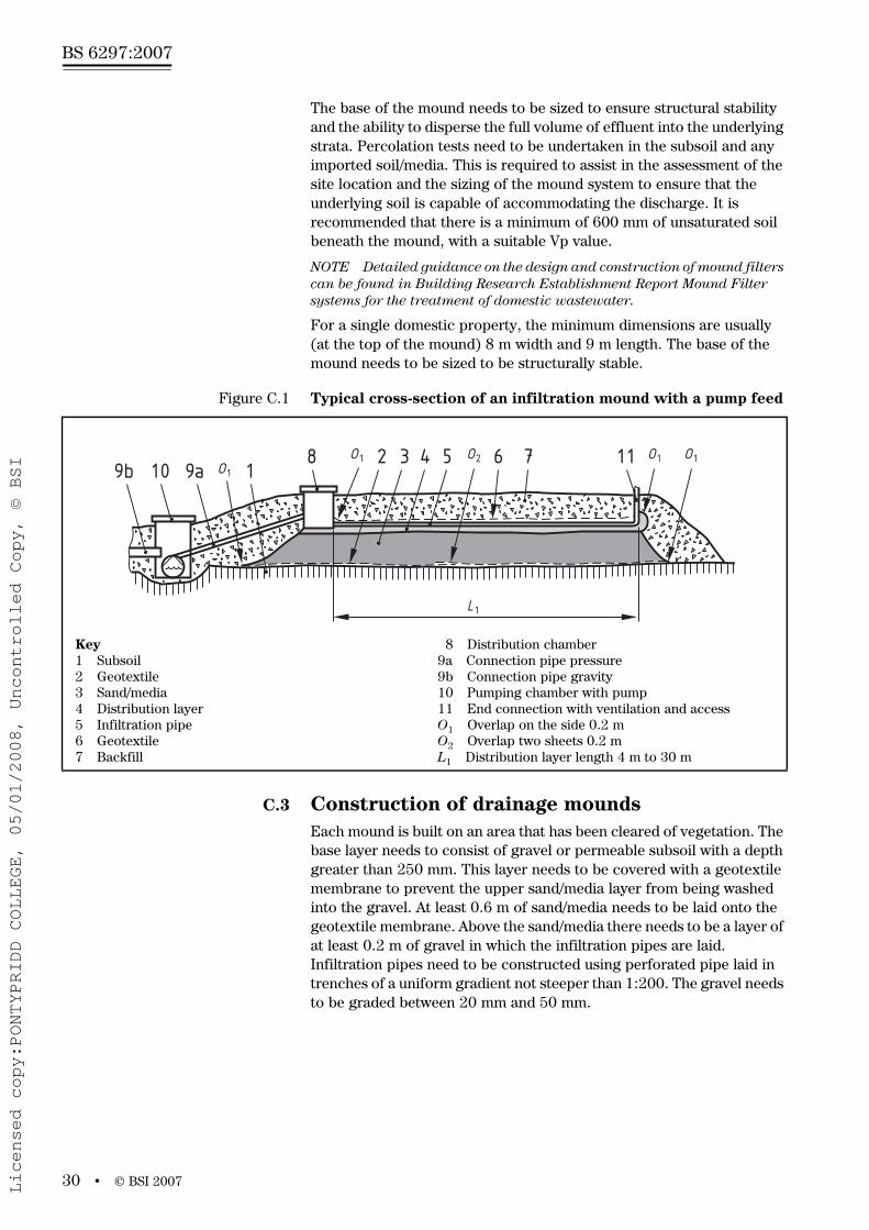
For a single domestic property, the minimum dimensions are usually (at the top of the mound) 8 m width and 9 m length. The base of the mound needs to be sized to be structurally stable.
C.3 Construction of drainage mounds Each mound is built on an area that has been cleared of vegetation. The base layer needs to consist of gravel or permeable subsoil with a depth greater than 250 mm. This layer needs to be covered with a geotextile membrane to prevent the upper sand/media layer from being washed into the gravel. At least 0.6 m of sand/media needs to be laid onto the geotextile membrane. Above the sand/media there needs to be a layer of at least 0.2 m of gravel in which the infiltration pipes are laid. Infiltration pipes need to be constructed using perforated pipe laid in trenches of a uniform gradient not steeper than 1:200. The gravel needs to be graded between 20 mm and 50 mm.
Figure C.1 Typical cross-section of an infiltration mound with a pump feed
Key1 Subsoil2 Geotextile3 Sand/media4 Distribution layer5 Infiltration pipe6 Geotextile7 Backfill
8 Distribution chamber9a Connection pipe pressure9b Connection pipe gravity10 Pumping chamber with pump11 End connection with ventilation and accessO1 Overlap on the side 0.2 mO2 Overlap two sheets 0.2 mL1 Distribution layer length 4 m to 30 m
L1
9b 10 9a 1O18 O1 2 3 4 5 O2 6 7 11 O1O1
Licensed copy:PONTYPRIDD COLLEGE, 05/01/2008, Uncontrolled Copy, © BSI

www.bzfxw.com
© BSI 2007 • 31
BS 6297:2007
The total depth of the gravel layer needs to be a minimum of 0.3 m with approximately 0.1 m above the infiltration pipe. This layer needs to be covered with geotextile membrane. Where several sheets are needed, these have to be overlapped by 0.2 m to cover the entire surface. The complete geotextile membrane covering needs to be wider than the mound. The whole constructed mound needs to be covered by topsoil to a thickness of at least 0.25 m and seeded with grass.
Due to the elevation of the mound a pump might be necessary to raise the effluent.
The construction of a mound system can be problematic and where a mound is identified as the most suitable drainage field design, consideration needs to be given to the installation of a wastewater treatment plant producing higher quality effluent.
C.4 Constructed wetlands/reed bedsReed bed treatment systems or other constructed wetland treatment systems can be used to provide secondary or tertiary treatment of effluent from septic tanks or packaged treatment plants. The systems treat wastewater as it moves through the gravel bed around the rhizomes and roots, by removing organic matter (BOD), oxidizing ammonia, reducing nitrate and removing phosphorus. The mechanisms are complex and involve bacterial oxidation, filtration, sedimentation, adsorption and precipitation.
Reed beds generally use the Common Reed (Phragmites australis). Other types of plants used in constructed wetlands include Reed Maces (Typha latifolia), rush (Juncus effusus) and true Bulrush (Schoenoplectus lacustris), as well as members of the Sedge family (Carex) and Yellow Flag (Iris pseudacorus).
Constructed wetlands should not be constructed in the shade of trees or buildings as this might result in poor or patchy growth. Although winter performance is generally similar in respect to removal of BOD and suspended solids, it tends to be poorer than in summer for removal of ammonia due to lower temperatures. This needs to be taken into consideration during the design stage.
There are two main designs of constructed wetland system – horizontal flow and vertical flow. The operating conditions within each type of bed vary significantly and they are suitable for different applications.
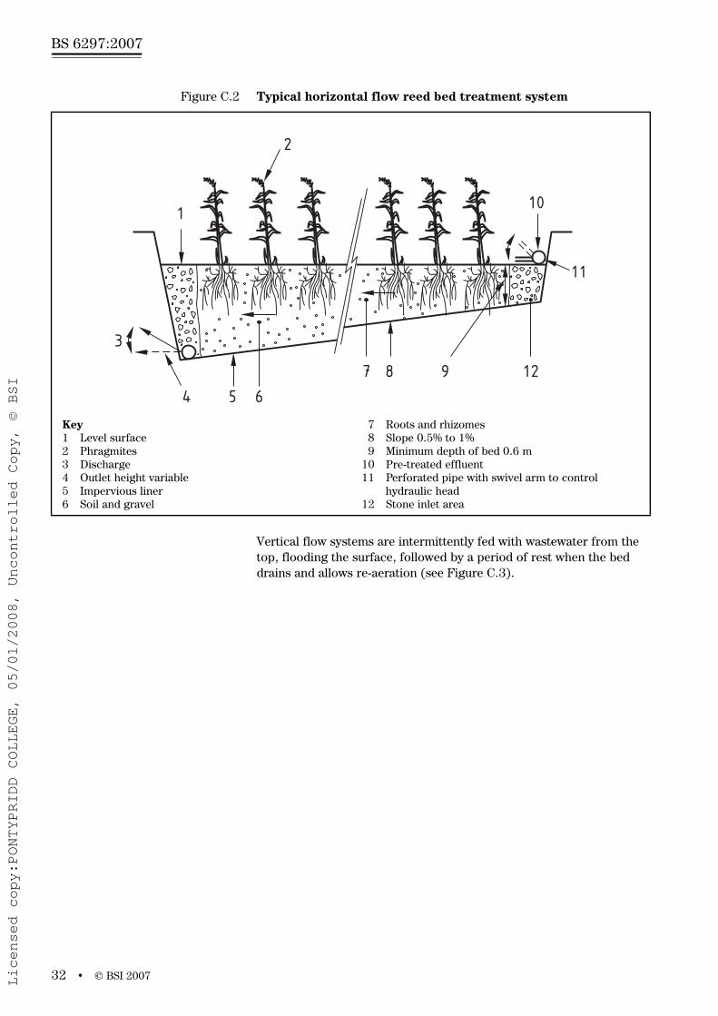
Horizontal flow systems are continuously fed with wastewater from one end. The effluent flows horizontally through the gravel bed over the full width of the bed to the outlet end (see Figure C.2).
The bed is submerged and horizontal flow systems are oxygen-limited. Therefore, they tend not to be able to completely treat concentrated effluents, particularly those with high levels of ammonia, and generally only achieve satisfactory effluent quality with respect to BOD and suspended solids. Horizontal flow systems require a level site. As they only use a single bed, less maintenance is required than with vertical flow systems.
Licensed copy:PONTYPRIDD COLLEGE, 05/01/2008, Uncontrolled Copy, © BSI
www.bzfxw.com
BS 6297:2007
32 • © BSI 2007
Vertical flow systems are intermittently fed with wastewater from the top, flooding the surface, followed by a period of rest when the bed drains and allows re-aeration (see Figure C.3).
Figure C.2 Typical horizontal flow reed bed treatment system
Key1 Level surface2 Phragmites3 Discharge4 Outlet height variable5 Impervious liner6 Soil and gravel
7 Roots and rhizomes8 Slope 0.5% to 1%9 Minimum depth of bed 0.6 m
10 Pre-treated effluent11 Perforated pipe with swivel arm to control
hydraulic head12 Stone inlet area
1
2
3
4 5 6
7 8 9 12
10
11
Licensed copy:PONTYPRIDD COLLEGE, 05/01/2008, Uncontrolled Copy, © BSI

www.bzfxw.com
© BSI 2007 • 33
BS 6297:2007
Two or more beds are normally provided so that they can be used in rotation. The flow is predominantly downward to an outlet at the bottom and is collected by a drainage network at the base. They therefore require a fall of between 1 m to 2 m. Vertical flow systems can achieve much better oxygen transfer than horizontal flow systems and therefore achieve more complete treatment, particularly of ammonia. They are less efficient at removing suspended solids and generally require more maintenance than horizontal flow systems.
Two stage systems with a vertical flow bed followed by a horizontal bed can be used to exploit the strengths of both systems.
Guidance on the design of reed bed treatment systems can be found in Building Research Establishment (BRE) report, Reed beds for the treatment of domestic wastewater [10], the Good Building Guide No. 42 [12] and Reed Beds and Constructed Wetlands for Wastewater Treatment [13].
Figure C.3 Typical vertical flow reed bed treatment system
Key1 “Sharp” sand2 6 mm washed pea-gravel3 12 mm round, washed gravel4 30-60 mm round, washed gravel5 Feed dosed intermittently over whole surface6 Solid pipe
7 Perforated pipe (~110 mm OD)8 LDPE Liner9 Network of porous pipes
10 1% slope11 Large stones12 Free draining outlet
21
6 34
7
5
8 9 10 11
12~150
~100
~150
~80
250
Licensed copy:PONTYPRIDD COLLEGE, 05/01/2008, Uncontrolled Copy, © BSI

www.bzfxw.com
BS 6297:2007
34 • © BSI 2007
BibliographyOther publications
[1] CEN/TR 12566-2:2005, Small wastewater treatment systems for up to 50 PT – Part 2: Soil infiltration systems.
[2] Environmental Agencies, Pollution Prevention Guidelines Note 4 (PPG4), Disposal of sewage where no main drainage is available, 2005.
[3] British Water, Code of practice, Flows and Loads – 2, Sizing criteria, treatment capacity for small wastewater treatment systems (package plants), London, 2004.
[4] GREAT BRITAIN. Construction (Health, Safety and Welfare) Regulations 1996, SI 1996/1592. The Stationery Office: London.
[5] GREAT BRITAIN. Construction (Design and Management) Regulations 1994, SI 1994/3140. The Stationery Office: London.
[6] GREAT BRITAIN. Confined Spaces Regulations 1997, SI 1997/1713. The Stationery Office: London.
[7] DETR circular 03/99, WO circular 10/99, Planning requirement in respect of the use of non-mains sewerage incorporating septic tanks in new development, 1999.
[8] GREAT BRITAIN. Water Resources Act 1991 as amended by the Environment Act 1995.
[9] NORTHERN IRELAND. Water (Northern Ireland) Order 1999, SI 1999/662 (N.I. 6).
[10]SCOTLAND. Water Environment (Controlled Activities) (Scotland) Regulations 2005, SSI 2005/348.
[11]N Grant and J Griggs, BR420, Reed beds for the treatment of domestic wastewater, Building Research Establishment (BRE), 2001.
[12]N Grant and J Griggs, GG42, Good Building Guide No. 42, BRE, 2000.
[13]PF Cooper et al, Reed Beds and Constructed Wetlands for Wastewater Treatment, WRC plc, 1996.
Further reading, standards publications
BS 4346-3, Joints and fittings for use with unplasticized PVC pressure pipes – Part3: Specification for solvent cement.
BS EN 295-1, Vitrified clay pipes and fittings and pipe joints for drains and sewers – Part 1: Requirements.
BS EN 295-2, Vitrified clay pipes and fittings and pipe joints for drains and sewers – Part 2: Quality control and sampling.
BS EN 295-3, Vitrified clay pipes and fittings and pipe joints for drains and sewers – Part 3: Test methods.
BS EN 295-4, Vitrified clay pipes and fittings and pipe joints for drains and sewers – Part 4: Requirements for special fittings, adaptors and compatible accessories.
Licensed copy:PONTYPRIDD COLLEGE, 05/01/2008, Uncontrolled Copy, © BSI

www.bzfxw.com
© BSI 2007 • 35
BS 6297:2007
BS EN 476, General requirements for components used in discharge pipes, drains and sewers for gravity systems.
BS EN 598, Ductile iron pipes, fittings, accessories and their joints for sewerage applications – Requirements and test methods.
BS EN 681-1, Elastomeric seals – Material requirements for pipe joint seals used in water and drainage applications – Part 1: Vulcanized rubber.
BS EN 773, General requirements for components used in hydraulically pressurized discharge pipes, drains and sewers.
BS EN 877, Cast iron pipes and fittings, their joints and accessories for the evacuation of water from buildings – Requirements, test methods and quality assurance.
BS EN 1123 (all parts), Pipes and fittings of longitudinally welded hot dip galvanized steel pipes with spigot and socket for waste water systems.
BS EN 1124 (all parts), Pipes and fittings of longitudinally welded stainless steel pipes with spigot and socket for waste water systems.
BS EN 1401-1, Plastics piping systems for non-pressure underground drainage and sewerage – Unplasticized poly(vinyl chloride) (PVC-U) – Part 1: Specifications for pipes, fittings and the system.
BS EN 1453-1, Plastics piping systems with structured-wall pipes for soil and waste discharge (low and high temperature) inside buildings – Unplasticized poly(vinyl chloride) (PVC-U) – Part 1: Specifications for pipes and the system.
BS EN 1852-1, Plastics piping systems for non-pressure underground drainage and sewerage – Polypropylene (PP) – Part 1: Specifications for pipes, fittings and the system.
BS EN 12056-2, Gravity drainage systems inside buildings – Part 2: Sanitary pipework, layout and calculation
BS EN 12255 (all parts), Wastewater treatment plants.
BS EN 13244 (all parts), Plastics piping systems for buried and above-ground pressure systems for water for general purposes, drainage and sewerage – Polyethylene (PE).
BS EN ISO 10320, Geotextiles and geotextile-related products – Identification on site.
PAS 27:1999 Unplasticized poly(vinyl chloride) alloy (PVC-A) pipes and bends for water under pressure.
Further reading, non-standards publications
Building Regulations Part H, Drainage and waste disposal, The Office of the Deputy Prime Minister (ODPM), 2006.
Building Standards Scotland Part M, Drainage and sanitary facilities, The Scottish Executive, 1990.
Planning policy statement No 14, Sustainable development in the countryside, Department for Regional Development, 2006.
Planning Advice Note PAN 79, Water and Drainage, The Scottish Government Publications, 2006.
Licensed copy:PONTYPRIDD COLLEGE, 05/01/2008, Uncontrolled Copy, © BSI

www.bzfxw.com
BS 6297:2007
36 • © BSI 2007
Small private sewage treatment plants, SP152L, Construction Industry Research and Information Association (CIRIA), 2001.
Septic tank systems: a regulator’s guide, CIRIA, SP144, 1998.
Richard D S Phelps and John Griggs, Mound filter systems for the treatment of domestic wastewater, BRE, 2005.
Water industry specifications (WIS) 4-31-08, Oriented Polyvinyl chloride (PVC-O) pressure pipes for underground use, 2001.
Groundwater Protection Code: Use and Construction of Septic Tanks and other Non-Mains Sewerage Systems, PB5803, DEFRA, 2006.
Licensed copy:PONTYPRIDD COLLEGE, 05/01/2008, Uncontrolled Copy, © BSI

www.bzfxw.com
This page deliberately left blank
BS 6297:2007
Licensed copy:PONTYPRIDD COLLEGE, 05/01/2008, Uncontrolled Copy, © BSI

www.bzfxw.com
BSI – British Standards InstitutionBSI is the independent national body responsible for preparing British Standards. It presents the UK view on standards in Europe and at the international level. It is incorporated by Royal Charter.
RevisionsBritish Standards are updated by amendment or revision. Users of British Standards should make sure that they possess the latest amendments or editions.
It is the constant aim of BSI to improve the quality of our products and services. We would be grateful if anyone finding an inaccuracy or ambiguity while using this British Standard would inform the Secretary of the technical committee responsible, the identity of which can be found on the inside front cover. Tel: +44 (0)20 8996 9000. Fax: +44 (0)20 8996 7400.
BSI offers members an individual updating service called PLUS which ensures that subscribers automatically receive the latest editions of standards.
Buying standardsOrders for all BSI, international and foreign standards publications should be addressed to Customer Services. Tel: +44 (0)20 8996 9001. Fax: +44 (0)20 8996 7001. Email: [email protected]. Standards are also available from the BSI website at http://www.bsi-global.com.
In response to orders for international standards, it is BSI policy to supply the BSI implementation of those that have been published as British Standards, unless otherwise requested.
Information on standardsBSI provides a wide range of information on national, European and international standards through its Library and its Technical Help to Exporters Service. Various BSI electronic information services are also available which give details on all its products and services. Contact the Information Centre. Tel: +44 (0)20 8996 7111. Fax: +44 (0)20 8996 7048. Email: [email protected].
Subscribing members of BSI are kept up to date with standards developments and receive substantial discounts on the purchase price of standards. For details of these and other benefits contact Membership Administration. Tel: +44 (0)20 8996 7002. Fax: +44 (0)20 8996 7001. Email: [email protected].
Information regarding online access to British Standards via British Standards Online can be found at http://www.bsi-global.com/bsonline.
Further information about BSI is available on the BSI website at http://www.bsi-global.com.
CopyrightCopyright subsists in all BSI publications. BSI also holds the copyright, in the UK, of the publications of the international standardization bodies. Except as permitted under the Copyright, Designs and Patents Act 1988 no extract may be reproduced, stored in a retrieval system or transmitted in any form or by any means – electronic, photocopying, recording or otherwise – without prior written permission from BSI.
This does not preclude the free use, in the course of implementing the standard, of necessary details such as symbols, and size, type or grade designations. If these details are to be used for any other purpose than implementation then the prior written permission of BSI must be obtained.
Details and advice can be obtained from the Copyright & Licensing Manager.Tel: +44 (0)20 8996 7070. Fax: +44 (0)20 8996 7553.Email: [email protected].
BS 6297:2007
389 Chiswick High RoadLondonW4 4AL
Licensed copy:PONTYPRIDD COLLEGE, 05/01/2008, Uncontrolled Copy, © BSI