buck-boost hookup guide - digi-key sheets/sparkfun pdfs/buck-boos… · the buck-boost converter is...
TRANSCRIPT
Buck-Boost Hookup Guide
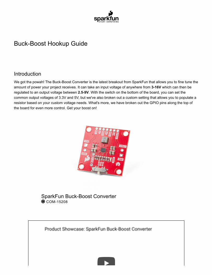
IntroductionWe got tha powah! The Buck-Boost Converter is the latest breakout from SparkFun that allows you to fine tune theamount of power your project receives. It can take an input voltage of anywhere from 3-16V which can then beregulated to an output voltage between 2.5-9V. With the switch on the bottom of the board, you can set thecommon output voltages of 3.3V and 5V, but we've also broken out a custom setting that allows you to populate aresistor based on your custom voltage needs. What's more, we have broken out the GPIO pins along the top ofthe board for even more control. Get your boost on!
SparkFun Buck-Boost Converter COM-15208
Product Showcase: SparkFun Buck-Boost ConverterProduct Showcase: SparkFun Buck-Boost Converter
Buck-Boost Hookup Guide Wish List SparkFun Wish List
Required Materials
To follow along with this tutorial, you will need the following materials. You may not need everything, depending onwhat you have. Add it to your cart, read through the guide, and adjust the cart as necessary.
SparkFun Buck-Boost ConverterCOM-15208
Small HeatsinkPRT-11510
These tiny little black anodized heatsinks are perfect for cooling off small surface-mount components such as the A…
Theragrip Thermal TapePRT-09771
Aavid Thermalloy Theragrip is a double sided tape for ceramic or metal heatsink packages. Theragrip provides bot…
Break Away Headers - StraightPRT-00116
A row of headers - break to fit. 40 pins that can be cut to any size. Used with custom PCBs or general custom head…
Tools
You may also need a soldering iron, solder, and general soldering accessories.
Suggested Reading
If you aren’t familiar with the following concepts, we recommend checking out these tutorials before continuing.
Soldering Iron - 60W (Adjustable Temperature) TOL-14456
Solder Lead Free - 15-gram Tube TOL-09163
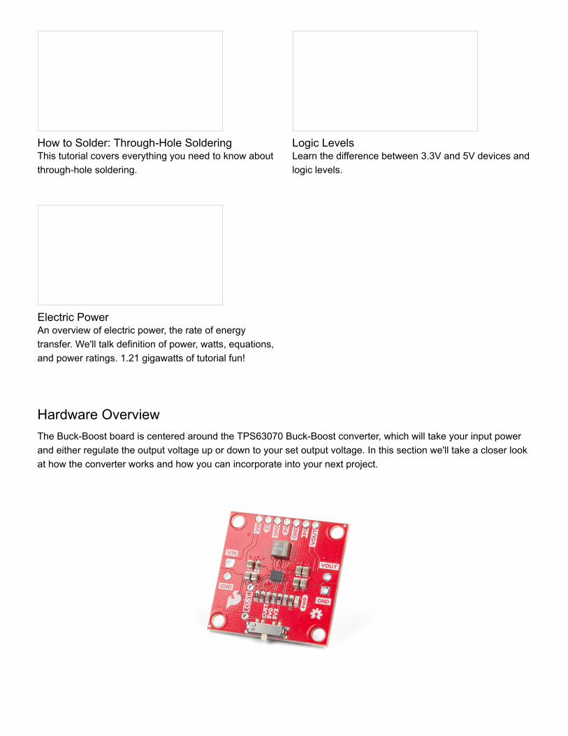
Hardware OverviewThe Buck-Boost board is centered around the TPS63070 Buck-Boost converter, which will take your input powerand either regulate the output voltage up or down to your set output voltage. In this section we'll take a closer lookat how the converter works and how you can incorporate into your next project.
How to Solder: Through-Hole SolderingThis tutorial covers everything you need to know aboutthrough-hole soldering.
Logic LevelsLearn the difference between 3.3V and 5V devices andlogic levels.
Electric PowerAn overview of electric power, the rate of energytransfer. We'll talk definition of power, watts, equations,and power ratings. 1.21 gigawatts of tutorial fun!
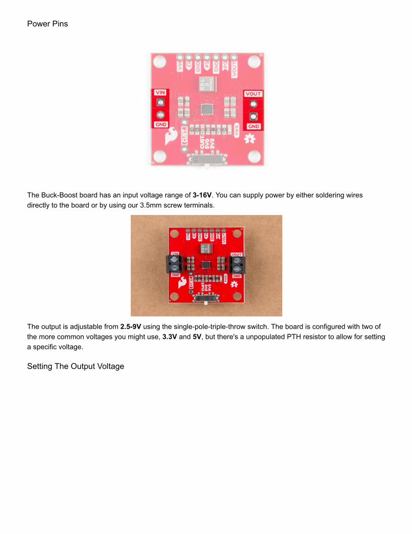
Power Pins
The Buck-Boost board has an input voltage range of 3-16V. You can supply power by either soldering wiresdirectly to the board or by using our 3.5mm screw terminals.
The output is adjustable from 2.5-9V using the single-pole-triple-throw switch. The board is configured with two ofthe more common voltages you might use, 3.3V and 5V, but there's a unpopulated PTH resistor to allow for settinga specific voltage.
Setting The Output Voltage
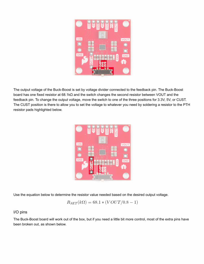
The output voltage of the Buck-Boost is set by voltage divider connected to the feedback pin. The Buck-Boostboard has one fixed resistor at 68.1kΩ and the switch changes the second resistor between VOUT and thefeedback pin. To change the output voltage, move the switch to one of the three positions for 3.3V, 5V, or CUST.The CUST position is there to allow you to set the voltage to whatever you need by soldering a resistor to the PTHresistor pads highlighted below.
Use the equation below to determine the resistor value needed based on the desired output voltage.
I/O pins
The Buck-Boost board will work out of the box, but if you need a little bit more control, most of the extra pins havebeen broken out, as shown below.

Pin Description
VIN Supply voltage for power stage. Can be used to pass power to the rest of the project, or used to setthe logic level.
EN Enable input. Pull high to enable the device. Pull Low to disable the device. Default: HIGH through10kΩ pull-up resistor to VIN.
GND Ground. Can be used to set I/O pin low.
PS Power Save. Pull low for forced PWM. Pull high for power save mode. In power save mode, theswitching frequency will adjust to the most efficient frequency. You can also apply a clock signal tosynchronize to an external frequency. Default: HIGH through 10kΩ pull-up resistor to VIN.
PG Power good open drain output.
VOUT Additional buck-boost converter output.
PWR LED

The power LED indicates red when voltage is present on the output pins. Because the LED has a fixed 1k currentlimiting resistor in series, the brightness of the LED will vary depending on the output voltage. The LED can bedisabled by cutting the jumper on the back of the board as shown below.
Buck-Boost Tips and Tricks
Maximum Output Current VS Input Voltage
One of the benefits of the Buck-Boost, aside from boosting the output voltage up from a lower input voltage, is ituses a switching DC/DC converter, which is more efficient than a linear regulator. More efficiency means lessenergy is wasted in the form of heat. However, that doesn't mean the TPS63070 doesn't get hot under load. TheTPS63070 has an operating die temperature range of -40 to +125°C, using the graphs below should provide agood rule of thumb for the maximum output current available at various output voltages as a function of the inputvoltage.
The temperature was recorded using a FLIR camera with an air temperature of 25°C, with a maximum casetemperature of 100°C. Each output voltage graph has a showing the maximum output current both with andwithout a heatsink.
Click on the photo for full resolution

Adding a Heatsink
In the maximum output current section, the graphs are shown both with and without a heatsink. The benefit of aheatsink is it provides more surface area for the air to dissipate the heat, which will allow the Buck-Boost board tooutput the maximum amount of current across a wider input voltage range. To add a heatsink you'll need two ofour products: a heatsink (of course), and our thermal tape.
To add a heatsink first cut the thermal tape to rough size:
Peel off one of the protective coverings and attach attach heatsink to thermal tape:
With a hobby knife, follow the perimeter of the heatsink to cut the tape to it's final size:
Remove the remaining protective covering of the tape and attach the heatsink to the TPS63070, trying to centerthe heatsink over the IC:
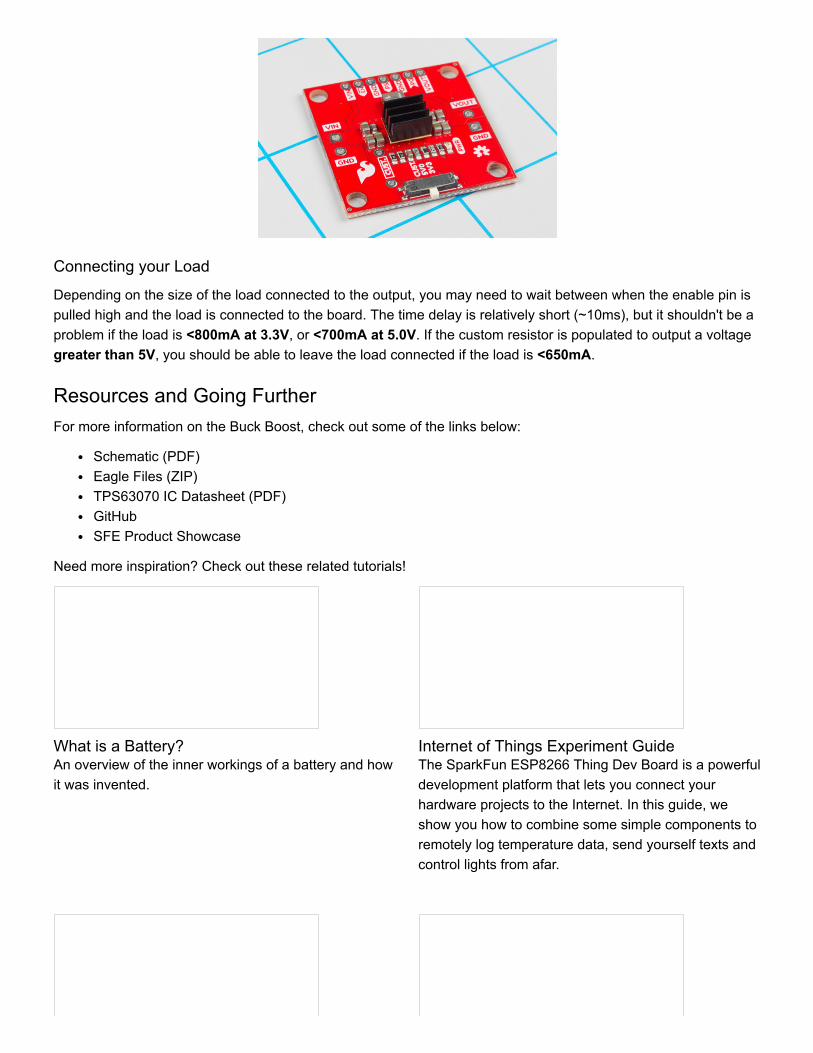
Connecting your Load
Depending on the size of the load connected to the output, you may need to wait between when the enable pin ispulled high and the load is connected to the board. The time delay is relatively short (~10ms), but it shouldn't be aproblem if the load is <800mA at 3.3V, or <700mA at 5.0V. If the custom resistor is populated to output a voltagegreater than 5V, you should be able to leave the load connected if the load is <650mA.
Resources and Going FurtherFor more information on the Buck Boost, check out some of the links below:
Schematic (PDF)Eagle Files (ZIP)TPS63070 IC Datasheet (PDF)GitHubSFE Product Showcase
Need more inspiration? Check out these related tutorials!
What is a Battery?An overview of the inner workings of a battery and howit was invented.
Internet of Things Experiment GuideThe SparkFun ESP8266 Thing Dev Board is a powerfuldevelopment platform that lets you connect yourhardware projects to the Internet. In this guide, weshow you how to combine some simple components toremotely log temperature data, send yourself texts andcontrol lights from afar.

Current Sensor Breakout (ACS723) HookupGuideLearn how to measure the current consumption of yourproject using the ACS723 Current Sensor.
LuMini Ring Hookup GuideThe LuMini Rings (APA102-2020) are the highestresolution LED rings available.