bucket elevator manual - ideal industries · bucket elevator. when the bucket elevator is connected...
TRANSCRIPT

BUCKET ELEVATORINSTALLATION & OPERATION MANUAL

BUCKET ELEVATORSINSTALLATION & OPERATION MANUAL
TABLE OF CONTENTS
2 .............. INTRODUCTION
3 .............. WARRANTY
4 .............. UNCRATING & ELECTRICAL REQUIREMENTS
5 .............. ASSEMBLY, BASIC COMPONENTS
6 .............. INSTALLATION
7 .............. INSTALLATION
8 .............. BELTS & CUPS
9 ............... ASSEMBLY, FINAL ADJUSTMENTS
10 ............. SAFETY
11 ............... PROBLEM I REMEDY
12 ............... PROBLEM I REMEDY
PAGE
1705 E STREET WEST • VINTON, IOWA 52349T: 800-332-0005 • T: 319-472-5224 • F: 319-472-5115
www.idealii.com
INTRODUCTION
This IDEAL Bucket Elevator Manual will confine its scope to general information on a “standard leg installation.” The variety of leg sizes, up to 60,000 BPH , would make a single, complete, installation manual impossible to compile. In addition, the location of the leg installation such as inside a leg well, in a tower system supported alongside another structure or a guyed, free-standing system, prohibit such a manual. Further, site preparation, erecting devices such as hoists or cranes (or the lack of them), and, most importantly, a contractor’s experience and techniques, will necessarily limit this manual to an overview of some common approaches.
The most important consideration during the installation process is following the various manufacturer’s instructions for the many components that make up the bucket elevator. If the installer is unsure about any phase of the installation, please contact us for assistance. We can answer most of your questions or suggest professional services to help you complete the installation.
INTRODUCTION
This manual provides installation, operation, service recommendations and replacement parts identification for IDEAL Bucket Elevators.
Each section of the manual is fully illustrated for fast, accurate reference. It is highly recommended that this manual be read thoroughly by those who are responsible for the installation, operation and maintenance of this elevator. Refer to the Table of Contents, Pate 1 for the location of specific information.
As new information and equipment become available, service and parts bulletins will be issued by IDEAL. This manual covers standard elevator equipment only. For any items or special equipment not covered in this manual, please consult our service department for recommendations or instructions regarding this equipment.
USE OF MANUAL
Our service department will provide consultation on installation, operation and maintenance at no cost to you. Also, information from you, regarding encountered operation or service problems that are not covered in this manual will be greatly appreciated.
Contact IDEAL for information on addingnew equipment to your system or changing your installation such as: Lengthening or shortening trunking, horsepower and speed requirements, etc.IDEAL keeps a complete record of each customer's order. However, valuable time can be saved if the information below is provided with your inquiry. It is suggested that you obtain the model number and serial number from the Packing Slip, or on the bucket elevator SN location, and enter it below for each bucket elevator in your system.
INFORMATION SERVICE
Date of Purchase
Model No. Serial No.
IDEAL1705 E Street WestVinton, IA 52349(800) 648-2243 or (319) 472-5224
Write or Call:
SAFETY CODE
CAUTION
SAFETY FIRST
The icon shown below was proposed as a safety alert symbol by the Farm and Industrial Equipment Institute (FIEI) and approved by the American Society of Automotive Engineers (ASAE) and others for the purpose of calling attention to safety precautions which if not heeded might lead to bodily injury.
Please read instructions carefully and follow the instructions exactly wherever this symbol appears in the manual.
www.idealii.com page 2

WARRANTY
WARRANTY: IDEAL WARRANTS ALL PRODUCTS MANUFACTURED BY IDEAL TO BE FREE OF DEFECTS IN MATERIAL AND WORKMANSHIP UNDER NORMAL USAGE AND CONDITIONS FOR A PERIOD OF TWELVE MONTHS AFTER RETAIL SALE OF THE ORIGINAL END USER OF SUCH PRODUCTS. IDEAL'S ONLY OBLIGATION IS, AND PURCHASER'S SOLE REMEDY SHALL BE, FOR IDEAL TO REPAIR OR REPLACE, AT IDEAL'S SOLE JUDGMENT, ON DEFECT DUE TO MATERIALS OR WORKMANSHIP. ALL DELIVERY AND SHIPMENT CHARGES TO AND FROM IDEAL'S FACTORY WILL BE THE PURCHASER'S RESPONSIBILITY, EXPENSES INCURRED BY OR ON BEHALF OF THE PURCHASER, WITHOUT PRIOR WRITTEN AUTHORIZATION FROM AN AUTHORIZED EMPLOYEE OF IDEAL, SHALL BE THE SOLE RESPONSIBILITY OF THE PURCHASER.
EXCEPT FOR THE ABOVE STATED EXPRESS LIMITED WARRANTIES, IDEAL MAKES NO WARRANTY OF ANY KIND, EXPRESSED OR IMPLIED, INCLUDING, WITHOUT LIMITATION, WARRANTIES OF MERCHANTABILITY OR FITNESS FOR A PARTICULAR PURPOSE OR USE IN CONNECTION WITH (1) PRODUCT MANUFACTURED OR SOLD BY IDEAL OR (2) ANY ADVICE, INSTRUCTION, RECOMMENDATION, OR SUGGESTION PROVIDED BY AN AGENT, REPRESENTATIVE OR EMPLOYEE OF IDEAL REGARDING OR RELATED TO THE CONFIGURATION, INSTALLATION, LAYOUT, SUITABILITY FOR A PARTICULAR PURPOSE, OR DESIGN OF SUCH PRODUCT OR PRODUCTS.
IN NO EVENT SHALL IDEAL BE LIABLE FOR ANY DIRECT, INDIRECT, INCIDENTAL OR CONSEQUENTIAL DAMAGES, INCLUDING, WITHOUT LIMITATION, LOSS OF ANTICIPATED PROFITS OR BENEFITS.
PURCHASER'S SOLE AND EXCLUSIVE REMEDY SHALL BE LIMITED TO THAT STATED ABOVE, WHICH SHALL NOT EXCEED THE AMOUNT PAID FOR THE PRODUCT PURCHASED. THIS WARRANTY IS NOT TRANSFERABLE AND APPLIES ONLY TO THE ORIGINAL PURCHASER. IDEAL SHALL HAVE NO OBLIGATION OR RESPONSIBILITY FOR ANY REPRESENTATIVE OR WARRANTIES MADE BY OR ON BEHALF OF ANY DEALIER, AGENT OR DISTRIBUTOR OF IDEAL.
IDEAL ASSUMES NO RESPONSIBILITY FOR FIELD MODIFICATIONS OR ERECTION DEFECTS, WHICH CREATE STRUCTURAL PROBLEMS. MODIFICATIONS TO THE PRODUCT NOT SPECIFICALLY COVERED BY THIS MANUAL WILL NULLIFY ANY PRODUCT WARRANTY THAT MIGHT HAVE BEEN OTHERWISE AVAILABLE.
THE FOREGOING WARRANTY SHALL NOT COVER PRODUCTS OR PARTS, WHICH HAVE BEEN DAMAGED BY NEGLIGENT USE. MISUSE, ALTERATION OR ACCIDENT. THIS WARRANTY COVERS ONLY THE PRODUCTS MANUFACTURED BY IDEAL. THIS WARRANTY IS EXCLUSIVE AND IN LIEU OF ALL OTHER WARRANTIES EXPRESS OR IMPLIED. IDEAL RESERVES THE RIGHT TO MAKE DESIGN OR SPECIFICATION CHANGES AT ANYTIME.
PRIOR TO INSTALLATION, PURCHASER HAS THE RESPONSIBILITY TO RESEARCH AND COMPLY WITH ALL FEDERAL, STATE AND LOCAL CODES, WHICH MAY APPLY TO THE LOCATION AND INSTALLATION.
TITLE AND RISK OF LOSS. Possession may be given before the final payment is due but; in order to protect IDEAL against: payment default; it is hereby agreed: 1) Purchaser gives IDEAL a security interest in the equipment and the proceeds of the equipment of the equipment is sold 1(a third party). Purchaser shall allow IDEAL 1) enter the premises of the Purchaser peacefully to take back the equipment or to receive the proceeds of the sale of the equipment. This Agreement shall act as a first lien or any such proceeds and the Purchaser agrees to allow IDEAL to file this Agreement in the Secretary of State's o�ce of the State in which the Purchaser is located to perfect IDEAL's lien, and to secure payment for the sale of the equipment 2) No part of this equipment shall be considered a fixture or incorporated into the realty by virtue of its attachment to the realty; 3) IDEAL shall have the right to elect a claim of merchant's lien against the property upon which this material is situated and waive IDEAL's rights to repossess under paragraphs 1 and 2 above any time, before expiration of terms fixed by law for filing the mechanic's lien.
The title and right to possess this material and equipment shall remain with IDEAL until full and final payment is made. Even though title remains in the Seller, risk of loss or damage is the responsibility of the Purchaser once the equipment is delivered to the shipping site.
WARRANTY INFORMATION
www.idealii.com page 3
ASSEMBLY & INSTALLATION
All parts have been carefully checked before shipment from our factory. Carefully inspect all parts for damage that may have occurred during shipment. Look for dents in trunking sections and bent or misaligned flanges or shafts. If these are not corrected, one can expect continuing problems and reduced life of the bucket elevator.
Check to make sure that all items listed in your Packing List are included.
If damages or shortages are noted, have the transportation company's representative note this on the Bill of Lading and notify IDEAL. Locate the model and serial number on the bucket elevator drive side and reference the missing or damaged part from the Packing List. Forward this information along with the shipping date so that we may expedite the replacement parts.
IMPORTANTAll claims for shipping damages must be noted by the consignee at the time of delivery and filed with the transportation company.
UNCRATING AND INSPECTION
CAUTION
The lifting bracket located in the top of the head section cover is for removing cover from head section only “Do not attempt to lift entire head section with this cover lifting bracket.
All electrical connections should be made by a qualified electrician. Check local codes before installation. A lockable external line disconnect switch, in compliance with local codes, must be provided and located as close as possible to the bucket elevator.
When the bucket elevator is connected with other machinery, electrical interlock priorities shouldbe maintained so that if any other equipment fails, all preceding equipment would stop.
ELECTRICAL REQUIREMENTS
CAUTION
Before removing bucket elevators covers or drive guards to attempt any repairs or adjustments, shut o� and lock the line disconnect switch. For electrical information on optional equipment, see appropriate section or specific engineering drawings in the back of this manual.
www.idealii.com page 4

ASSEMBLY AND INSTALLATION
Various combinations of components are shown in Figure 1. Your leg will di�er from this depending on the model and options ordered. The Bill of Materials will list the components you have received and indicate what fasteners are required for assembly.The following instructions refer to the assembly of a typical leg similar to that shown in Figure 1.The boot section should be fastened securely on a suitable foundation and shimmed to level in all directions. In some cases the boot should sit onproperly sized channels to keep water from infiltrating the system. The boot inlet hoppers should be attached at the level recommended by us in our catalog. If there is a question regarding proper feeding on the up or downside of the boot, it must be resolved at this time.
The first few sections of trunking that attach to the boot need special consideration. The best position for the access door and inspection port should be determined and located accordingly. Note that the inspection port is located on the upside and may be re-assembled to locateit at positions other than as shipped.
Trunking is fabricated in 10’ standard lengths and is precisely jig welded to insure a straight leg. Check each flange as it is assembled for damage and straighten or replace if necessary. The tie braces should be studied so their assembly corresponds with ladder, cage, and rest platforms, if used. Tighten bolts evenly, making sure the sections are not twisted. This joint must be smooth inside so a bucket cannot catch on it. Standard trunking sections are symmetrical and therefore can be placed without regard to direction. The short section is usually placed just below the head section rather than at the boot or center of the leg. Plumb the trunking in all directions as it is assembled and check it again after the installation is complete.
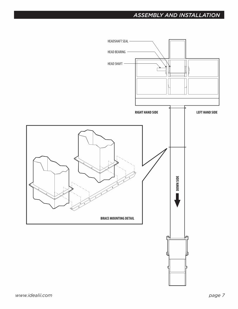
The head section must support the dynamic forces imposed by the drive, discharging buckets, attached spouts, service platform, wind and numerous other stresses. Proper guying or bracing to other structures is imperative. Besides the obvious catastrophic failure and collapse of the leg if not properly braced, less obvious and troublesome maintenance and/or operational “bugs” are sure to plague its operation.
ASSEMBLY OF BASIC COMPONENTS
It is the responsibility of the installing contractor to assemble the drive mechanism so that it will conform to all safety and electrical codes, regardless if the drive is furnished with the leg or whether it is supplied by the contractor or user. In all cases, the installer must see to it that all manufacturer’s instructions for installation and start up preparation have been followed. In those instances where we do not supply the drive, please consult us for horsepower and speed requirements.
A common drive for legs is the shaft-mounted type. This drive is often used because the reducer is mounted directly on the head shaft, eliminating high torque final chain drives. A torque arm is used to resist drive rotation and provide belt adjustment. We can provide the brackets necessary for the proper attachment of these components. Follow the drive manufacturer’s instructions if these brackets are not included.
If a backstop is required, care must be takento turn the drive in the proper rotation by hand to see that it has been installed properly.
DRIVES
CAUTIONAfter the motor is mounted but before the belts are attached, run the motor to check rotation before attaching the drive belt, coupling or chain.
www.idealii.com page 5
It is necessary to have the head shaft perfectly level so the belt will track properly on the head pulley.Place shims between the bearings and bridge trees if necessary. The bearing adjustment blocks located on the end of each bearing and the jack bolt located under the bearing and bridge tree will assist in truing up the pulley.

ASSEMBLY AND INSTALLATION
RELIEF VENT
DRIVE
HOOD
HEAD SECTION
INSPECTION PORT
BRIDGE TREE
THROAT PORT
ADJUSTABLETHROA
THROAT PLATE
SHORT SECTION
TIE BRACE(SEE DETAIL ONNEXT PAGE)
TRUNKING
BELT BUCKET
TAKEUPS
BOOT PULLEY
BOOT POCKET(OPTIONAL)
CLEANOUT SLIDE
HEAD PULLEY
INSPECTION SECTION
ACCESS DOORS
INSPECTION BOX
BOOT POCKET (STANDARD)
SHOVEL POCKET (OPTIONAL)
BOOT SECTION
BOOT BEARING
LAGGINGINSPECTION PORT(BOTH SIDES)
GUARD
SERVICE PLATFORM
MOTOR
DOWN SIDEUP SID E
Figure 1 : INSTALLATION
www.idealii.com page 6
ASSEMBLY AND INSTALLATION
HEADSHAFT SEAL
HEAD BEARING
HEAD SHAFT
DOW
N SI
DE
RIGHT HAND SIDE
BRACE MOUNTING DETAIL
LEFT HAND SIDE
www.idealii.com page 7

The belt is usually pulled through the access door on the upleg, around the head pulley, boot pulley and back to the door where it is spliced. The lap splice is standard and is used unless another type has been specifically ordered. See Figure 2. Additional belt length has been furnished so that six cups may be bolted over the lap. Long cup bolts called “splice bolts” on the Bill of Materials are included for this lap area. The proper direction for the lap is shown in Figure 3.
With the boot pulley in the highest take-up position, let the belt hang, with the cups attached, for 24 hours if possible. This will remove almost all of the initial stretch and will require less adjustment during the break-in period.
BELT & CUPS
Figure 2
Cups are attached using the washers supplied. Be sure to tighten the nuts adequately to ensure a good “set” of the head into the back of the belt.
STANDARD LAP SPLICE
1/4” diameter
5/16” diameter
3/8” diameter
84
168
288
7
14
24
Recommended Maximum Torque for Elevator Bolts
ASSEMBLY AND INSTALLATION
BAR CLAMP BELT SPLICE
BOTH
DIR
ECTIO
NS O
F BUT
T SPL
ICE(6
) CUP
LAP S
PLICE
(6) C
UP LA
P SPL
ICEBO
TH D
IREC
TIONS
OF B
UTT S
PLICE
(6) C
UP
LAP
SPLI
CE
In./Lbs. Ft./lbs
Figure 3
www.idealii.com page 8
BAR CLAMP BELT SPLICE BUTT STRAP SPLICE
ROTATION
6” Dia. Pulley 10” Dia. Pulley 16” Dia. Pulley 20” Dia. Pulley 24” Dia. Pulley 30” Dia. Pulley 36” Dia. Pulley 42” Dia. Pulley 48” Dia. Pulley7” Wide Belt 8” Wide Belt 10” Wide Belt 12” Wide Belt 12” Wide Belt 14” Wide Belt 14” Wide Belt 19” Wide Belt 19” Wide Belt
20’ 11 7 6 8 7 11 11 22 20
30’ 16 11 8 12 10 17 17 34 29
40’ 21 14 11 16 13 22 23 45 39
50’ 26 18 14 20 17 28 28 56 49
60’ 32 22 17 24 20 33 34 67 59
70’ 37 25 20 28 23 39 39 78 68
80’ - 29 23 32 27 44 45 89 78
90’ - 32 25 36 30 50 51 101 88
100’ - 36 28 40 33 55 56 112 98
110’ - - 31 44 37 61 62 123 108
120’ - - 34 48 40 67 68 134 117
130’ - - 37 52 43 72 73 145 127
140’ - - 39 56 47 78 79 157 137
150’ - - 42 60 50 83 84 168 147
160’ - - 45 64 54 89 90 179 157
170’ - - - 68 57 94 96 190 166
180’ - - - 72 60 100 101 201 176
190’ - - - - 64 105 107 212 186
200’ - - - - 67 111 113 224 196
210’ - - - - - 116 118 235 205
220’ - - - - - 122 124 246 215
230’ - - - - - 128 130 257 225
240’ - - - - - - 135 268 235
250’ - - - - - - 141 279 245
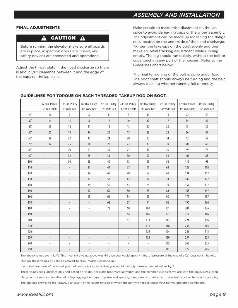
The above values are in lb/ft. This means if a value above was 44 then you would apply 44 lbs. of pressure at the end of a 12" long wench handle.
Multiply these values by 1.356 to convert to N/m (metric system value).
If you had two rows of cups and your belt was twice as wide then you would multiply these estimated values by 2.
These values are guidelines only and based on 45 lbs. per cubic foot material weight and the common cup sizes we use with the pulley sizes listed.
Many factors such as condition of pulley lagging, belt type, cup size and spacing, dampness, etc. will e�ect the actual required tension for your leg.
The obvious answer to the "IDEAL TENSION" is the lowest tension at which the belt will not slip under your normal operating conditions.
ASSEMBLY AND INSTALLATION
Adjust the throat plate in the head discharge so there is about 1/8" clearance between it and the edge of the cups on the lap splice.
Make certain to make this adjustment on the lap spice to avoid damaging cups or the wiper assembly. The adjustment can be made by loosening the flange nuts located on the underside of the head discharge.Tighten the take-ups on the boot evenly and then make an initial tracking adjustment while running empty. The leg should run quietly, without the belt or cups touching any part of the housing. Refer to the Guidelines chart below.
The final tensioning of the belt is done under load. The boot shaft should always be turning and the belt always tracking whether running full or empty.
FINAL ADJUSTMENTS
GUIDELINES FOR TORQUE ON EACH THREADED TAKEUP ROD ON BOOT.
CAUTIONBefore running the elevator make sure all guards are in place, inspection doors are closed, and safety devices are connected and operational.
www.idealii.com page 9
SAFETY
Slowdown monitors, explosions panels, belt alignment monitors, and other safety interlock equipment may be part of your installation.
Each of these should have specific instructions regarding installation and use and are not covered in this manual.
SAFETY DEVICES
These items, if supplied by us, have assembly drawings included with the shipment and are not covered in this manual.
Please request applicable drawings if you do not have them.
LADDER, CAGE & PLATFORMS
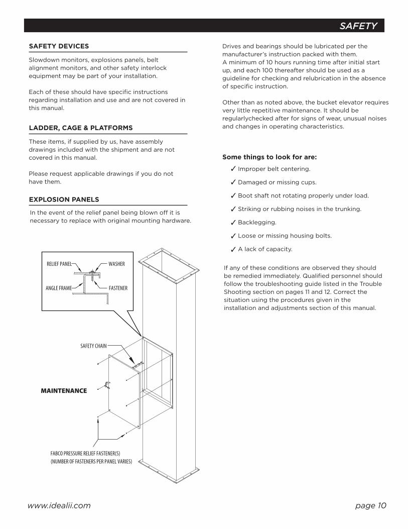
In the event of the relief panel being blown o� it is necessary to replace with original mounting hardware.
EXPLOSION PANELS
MAINTENANCE
FABCO PRESSURE RELIEF FASTENER(S)(NUMBER OF FASTENERS PER PANEL VARIES)
SAFETY CHAIN
ANGLE FRAME
RELIEF PANEL WASHER
FASTENER
Drives and bearings should be lubricated per the manufacturer’s instruction packed with them. A minimum of 10 hours running time after initial start up, and each 100 thereafter should be used as a guideline for checking and relubrication in the absence of specific instruction.
Other than as noted above, the bucket elevator requires very little repetitive maintenance. It should be regularlychecked after for signs of wear, unusual noises and changes in operating characteristics.
If any of these conditions are observed they should be remedied immediately. Qualified personnel should follow the troubleshooting guide listed in the Trouble Shooting section on pages 11 and 12. Correct the situation using the procedures given in the installation and adjustments section of this manual.
Improper belt centering.
Damaged or missing cups.
Boot shaft not rotating properly under load.
Striking or rubbing noises in the trunking.
Backlegging.
Loose or missing housing bolts.
A lack of capacity.
Some things to look for are:
www.idealii.com page 10
PROBLEM / REMEDY
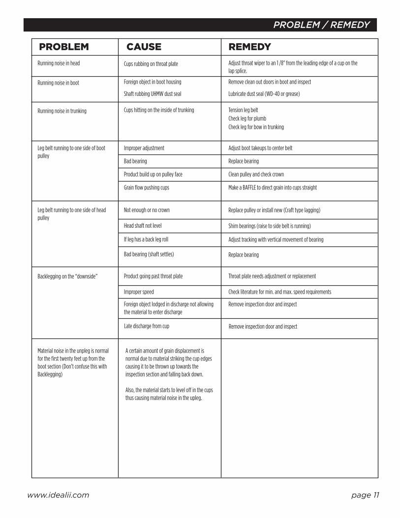
PROBLEM CAUSE REMEDYRunning noise in head
Running noise in boot
Running noise in trunking
Leg belt running to one side of boot pulley
Leg belt running to one side of head pulley
Backlegging on the “downside” Product going past throat plate
lmproper speed
Foreign object lodged in discharge not allowing the material to enter discharge
Late discharge from cup
Bad bearing (shaft settles)
If leg has a back leg roll
Head shaft not level
Not enough or no crown
Grain flow pushing cups
Product build up on pulley face
Bad bearing
Improper adjustment
Cups hitting on the inside of trunking
Shaft rubbing UHMW dust seal
Foreign object in boot housing
Cups rubbing on throat plate Adjust throat wiper to an 1 /8" from the leading edge of a cup on the lap splice.
Remove clean out doors in boot and inspect
Lubricate dust seal (WD-40 or grease)
Tension leg beltCheck leg for plumbCheck leg for bow in trunking
Adjust boot takeups to center belt
Replace bearing
Clean pulley and check crown
Make a BAFFLE to direct grain into cups straight
Replace pulley or install new (Craft type lagging)
Shim bearings (raise to side belt is running)
Adjust tracking with vertical movement of bearing
Replace bearing
Throat plate needs adjustment or replacement
Check literature for min. and max. speed requirements
Remove inspection door and inspect
Remove inspection door and inspect
Material noise in the unpleg is normal for the first twenty feet up from the boot section (Don’t confuse this with Backlegging)
A certain amount of grain displacement is normal due to material striking the cup edges causing it to be thrown up towards the inspection section and falling back down.
Also, the material starts to level o� in the cups thus causing material noise in the upleg.
www.idealii.com page 11

PROBLEM / REMEDY
PROBLEM CAUSE REMEDYLow capacity Cups not full (product should cover cup bolt)
Air locked material (usually only problem with light flu�y material)
Inadequate discharge spouting
Belt slippage
Wrong cups or cup spacing
Low horsepower
Material build-up in cups Wet or sticky surface materials that have been allowed to build up on the inside surface of the cup, can substantially reduce the volume of the cup. Periodically recirculating abrasive material in the leg may help keep the cups clean.
A poorly fed or overfed boot, or feeding on the downside will require additional horsepower.
If the belt speed decreases under load for reasons other than slippage, check all drive components including reducer ratio,sprocket or sheave diameters, and motor HP and RPM against the bill of materials. Readings for voltage and current draw under load will be helpful in assessing the problem.
Check to see that the correct cup type, size and spacing is used according to the specifications given in the bill of materials.
This is a dangerous condition and must be corrected immediately. A fire in the head section may result from the friction or the leg may plug.
This can be checked by observing the throat under full loading. If it fills with material up to the throat plate, it is an indication the spouting is poorly designed and must be corrected before full capacity can be realized.
This problem is caused by the leg acting as an air pump, creating pressure in the leg and not allowing the material to enter the boot. Proper venting and / or suction will be required.
Perforated cups may be required for light, flu�y material.
Belt speed too high or cup spacing too close (not allowing material to enter cup)flu�y material.
Upside inlet too low or boot pulley to high. Try lowering boot pulley to see if cup fill is improved.
Check feeding device
www.idealii.com page 12

• DRAG CONVEYORS
• EN MASSE CONVEYORS
• BEND SECTIONS
• BUCKET ELEVATORS
• PULLEYS
• HEAD SECTIONS
• TAIL SECTIONS
• MANUAL & PNEUMATIC GATES
• SERVICE PLATFORMS
•CUSTOM FABRICATION
CONVEYORS AND CONVEYOR COMPONENTS
HEAD & TAIL SECTIONS
BEND SECTION
CONVEYOR AND ELEVATOR INLETS
SEED ELEVATOR BUCKET ELEVATOR SERVICE PLATFORM
HEAD & TAIL SECTIONS
GATES
www.idealii.com page 13
PRODUCTS

PLEASE CONTACT OUR SERVICE SPECIALISTS FOR HELP WITH ANY QUESTIONS OR CONCERNS
ABOUT YOUR IDEAL BUCKET ELEVATOR.
1705 E STREET WEST • VINTON, IOWA 52349T: 800-332-0005 • T: 319-472-5224 • F: 319-472-5115
www.idealii.com