buckling strength of the cylindrical shell and tank subjected...
TRANSCRIPT

Thin-Walled Structures 40 (2002) 329–353www.elsevier.com/locate/tws
Buckling strength of the cylindrical shell andtank subjected to axially compressive loads
Seung-Eock Kim*, Chang-Sung KimDepartment of Civil and Environmental Engineering, Construction Tech. Research Institute, Sejong
University, 98 Kunja-dong, Kwangjin-ku, Seoul 143-747, South Korea
Received 7 June 2001; received in revised form 23 October 2001; accepted 23 October 2001
Abstract
This paper aims to develop practical design equations and charts estimating the bucklingstrength of the cylindrical shell and tank subjected to axially compressive loads. Both geometri-cally perfect and imperfect shells and tanks are studied. Numerical analysis is used to evaluatebuckling strength. The modeling method, appropriate element type and necessary number ofelements to use in numerical analysis are recommended. According to the results of the para-metric study of the perfect shell, the buckling strength decreases significantly as the diameter-to-thickness ratio increases, while it decreases slightly as the height-to-diameter ratio increases.These results are different from those in the case of columns. The buckling strength of theperfect tank placed on an extremely soft foundation and a stiff foundation increases by up to1.6% and 5.6%, respectively, compared with that of the perfect shell. The buckling strengthof the shell and tank decreases significantly as the amplitude of initial geometric imperfectionincreases. Convenient and sufficiently accurate design equations and charts used for estimatingbuckling strength are provided. 2002 Elsevier Science Ltd. All rights reserved.
Keywords: Cylindrical shell; Tank; Buckling strength; Initial geometric imperfection; Design equationand chart
1. Introduction
Cylindrical shells and tanks with very thin walls are susceptible to buckling whenthey are subjected to axially compressive loads. Analytical and experimental research
* Corresponding author.E-mail address: [email protected] (S.-E. Kim).
0263-8231/02/$ - see front matter 2002 Elsevier Science Ltd. All rights reserved.PII: S0263 -8231(01 )00066-0

330 S.-E. Kim, C.-S. Kim / Thin-Walled Structures 40 (2002) 329–353
on the buckling of cylindrical shell structures has been performed mainly in the fieldof mechanics and aeronautics. Goto and Shang [1] studied cylindrical shells withthickness-to-diameter ratio of less than 350 and height-to-diameter ratio greater than3. Their study was limited to relatively thick perfect shells that failed by plasticbuckling. Mandra and Mazzolani [2] researched cylindrical shells with diameter-to-thickness ratio less than 400 subjected to axial compression. They found that thethin cylindrical shells were very sensitive to initial geometric imperfections. Kimand Kardomateas [3] analyzed an orthotropic shell. Chryssanthopulos et al. [4] stud-ied stiffened cylinders. Soldatos [5] researched shells with non-circular cross-section.Donell and Wan [6], Miller [7] and Singer [8] performed experimental studies forrelatively thick cylindrical shells with diameter-to-thickness ratio of less than 400.Their test results showed the cylindrical shells buckle locally where initial geometricimperfections are large.
Melerski [9] performed linear elastic analysis of cylindrical tanks. Peek [10] ana-lyzed unanchored liquid storage tanks under lateral loads. Lau and Zeng [11]presented a simplified mathematical model for modeling the flexible bottom plate inan unanchored cylindrical tank. Malhotra [12] carried out uplifting analysis of cylin-drical tanks. Peek and El-Bkaily [13] studied postbuckling behavior of unanchoredsteel tanks under lateral loads. Nam and Lee [14] studied the unsymmetrically loadedcylindrical tank on an elastic foundation.
The aim of this paper is to investigate the buckling strength of the cylindricalshell and tank with diameter-to-thickness ratio of greater than 800, which are, ingeneral, used for large-scale storage of liquid. Generally, buckling analysis may bedivided into bifurcation and load–deflection analysis. Bifurcation analysis is used forperfect systems, while load–deflection analysis is used for imperfect systems. Thispaper presents the buckling strength of the geometrically perfect cylindrical shelland tank with a wide range of height-to-diameter and diameter-to-thickness ratios.The geometrically imperfect cylindrical shell and tank are also studied. Practicaldesign equations and charts estimating buckling strength of the cylindrical shells andtanks are proposed.
2. Geometrically perfect cylindrical shell
In this section, the buckling strength of the geometrically perfect cylindrical shellis presented. The analytical solution of the shell is widely known and briefly intro-duced herein. Numerical analysis is also performed. An appropriate element typeand the necessary number of elements to be used in numerical analysis are rec-ommended by comparing analytical and numerical results.
2.1. Analytical solution
If a cylindrical shell simply supported at the ends is uniformly compressed in theaxial direction as shown in Fig. 1, the general solution for very small displacementscan be given in the following form [15,16]:

331S.-E. Kim, C.-S. Kim / Thin-Walled Structures 40 (2002) 329–353
Fig. 1. Cylindrical shell subjected to axial load.
u � A sin nq cosmpxH
, (1)
v � B sin nq cosmpH
(2)
and
w � C sin nq cosmpH
, (3)
where A, B and C are constants; H is the height of the cylindrical shell; and n and mare the buckling number of circumferential and longitudinal half-waves, respectively.When the simply supported conditions of w � 0 and d2w /dx2 � 0 are used at theends, the critical stress is obtained as
scr �Nx
t�
RS
E(1�n2)
, (4)
where
R � (1�n2)l4 � a (n2 � l2)4�(2 � n)(3�n)l4n2 � 2l4(1�n2)�l2n4(7� n) � l2n2(3 � n) � n4�2n6 ,
S � l2�(n2 � l2)2 �2
1�n�l2 �1�n
2n2�[1 � a(n2 � l2)2]�
2n2l2
1�n

332 S.-E. Kim, C.-S. Kim / Thin-Walled Structures 40 (2002) 329–353
�2a
1�n�l2 �1�n
2n2�[n2 � (1�n)l2�,
a �t2
12R2,
l �mRp
H,
Nx is the axial force, E is Young’s modulus, n is Poisson’s ratio, t is the thicknessof the shell, and R is the radius of the shell. Theoretically, the critical stress of Eq.(4) has an infinite number of solutions as the values of m and n vary. The minimumcritical stress among these is determined as the buckling stress. One difficulty inusing Eq. (4) is that the m and n values leading to the buckling stress are unknownuntil a large number of critical stresses are calculated and compared. As a result,the equation essentially requires a lot of calculations of critical stresses dependingon the values of m and n in order to get the lowest critical stress, i.e. buckling stress.
Assuming that many buckling waves (m) form along the length of the cylinder,the value of l2 becomes large. Then, Eq. (4) can be simplified in the following form:
scr �Nx
t�
1�n2
E �a(n2 � l2)2
l2 �(1�n2)l2
(n2 � l2)2�. (5)
When the value of n in Eq. (5) is equal to zero, axisymmetric buckling occurs, andEq. (5) is simplified as
scr �Nx
t� D�m2p2
tH2 �E
R2DH2
m2p2�, (6)
where D � Et3 / [12(1�n2)] is the flexural rigidity. Since scr is a continuous functionof mp/H, the minimum value of Eq. (6) can be written in the following form:
scr �Et
R�3(1�n2). (7)
Analytical solutions given by Eqs. (4)–(7) will be used for the benchmark valuesin selecting an appropriate numerical model in Section 2.2.
2.2. Numerical analysis
Herein, an appropriate numerical model including the element type and necessarynumber of elements in numerical analysis is presented. A parametric study is perfor-med over a wide range for the cylindrical shell. An accurate design equation estimat-ing the buckling strength is proposed.

333S.-E. Kim, C.-S. Kim / Thin-Walled Structures 40 (2002) 329–353
2.2.1. Analysis methodBuckling analysis, in general, may be divided into bifurcation and load–deflection
analysis as shown in Fig. 2. Bifurcation buckling occurs when a maximum axialcompressive stress becomes equal to the buckling stress. The bifurcation analysiswas carried out using ABAQUS, a commercial finite element analysis program[17,18]. The equation of bifurcation analysis is expressed in the following form:
([K] � l[S]){y} � 0, (8)
where [K] is the stiffness matrix of the system, [S] is the stress stiffness matrix, lis an eigenvalue determining buckling load (or load factor), and {y} is an inherentvector determining buckling mode. If the load applied to the structure is QN, thecritical buckling load is lQN. This bifurcation analysis can capture both the bucklingstress and the failure mode of structures.
2.2.2. Selection of analysis modelThe dimensions of the cylindrical shell used were diameter of 20 m, height of 40
m and thickness of 0.025 m. The resulting diameter-to-thickness and height-to-diam-eter ratios are 800 and 2, respectively. Material properties were E �2 × 10¹¹ N/m2, n � 0.3 and sy � 3.2 × 10⁸ N/m2. When a full model was used,
ABAQUS did not predict the buckling mode and buckling strength accurately. Thusa half-model in height was used in this study (Fig. 3). The simply supported andthe symmetric boundary conditions were used for the bottom and top, respectively.In the following, an appropriate analytical model was selected by comparing theanalytical with the numerical results.
2.2.2.1. Element type Three-dimensional shell elements offered in ABAQUS canbe divided into four-node (S4R, S4R5) and eight-node (S8R, S8R5) shell elementsin view of the number of nodes per element, and five- (S4R5, S8R5) and six-degrees-
Fig. 2. Buckling analyses.

334 S.-E. Kim, C.-S. Kim / Thin-Walled Structures 40 (2002) 329–353
Fig. 3. Modeling of cylindrical shell: (a) full model; (b) half-model.
of-freedom (dof) (S4R, S8R) shell elements in view of the number of degrees offreedom per element. The 5-dof shell element has three displacement and tworotational components. The 6-dof shell element has three displacement and threerotational components. The critical stresses obtained by numerical analyses usingthese element types (Fig. 4) were compared with the theoretical stresses calculatedby Eq. (4). When element type S8R was used, the error in the buckling stress wasless than 1.4%. When elements S4R and S4R5 were used, the buckling stresses wereoverestimated by up to 15% even though a sufficient number of elements was used.Thus element type S8R was selected in numerical analysis.
2.2.2.2. Number of element Buckling strength was obtained using different num-bers of elements in both circumferential and axial directions. Analysis results werecompared with the theoretical ones given by Eq. (4) (Fig. 5). When the number ofelements in the circumferential direction increased from 12 to 32, the maximum errorreduced from 6.5% to 0.8%. It was preferable to keep the number of elements tomore than 20 in order to obtain accurate buckling strength.
Buckling stress was less sensitive to the number of elements in the axial directionthan to the number in the circumferential direction. When the number of elementsin the axial direction increased from 10 to 40, the maximum error reduced from0.8% to 0.4%. When 32 elements in the circumferential direction and 40 elementsin the axial direction were used, the buckling strength estimated was very accurate,within an error of 0.4%.

335S.-E. Kim, C.-S. Kim / Thin-Walled Structures 40 (2002) 329–353
Fig. 4. Critical stresses associated with mode shape corresponding to element type.
Fig. 5. Buckling stresses associated with different numbers of elements.

336 S.-E. Kim, C.-S. Kim / Thin-Walled Structures 40 (2002) 329–353
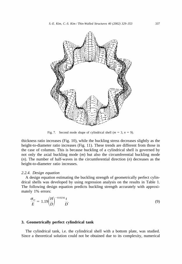
2.2.2.3. Buckling mode The first, second and third mode shapes obtained bynumerical analysis are shown in Figs. 6–8, respectively. The first mode occurs inm � 1 and n � 5, the second mode occurs in m � 3 and n � 9, and the third modeoccurs in m � 5 and n � 11. An axially symmetric buckling mode, one of higher-order modes, is shown in Fig. 9. This buckling mode occurs in m � 10 in the axialdirection and n � 0 in the circumferential direction. The buckling modes show goodagreement with the theoretical ones.
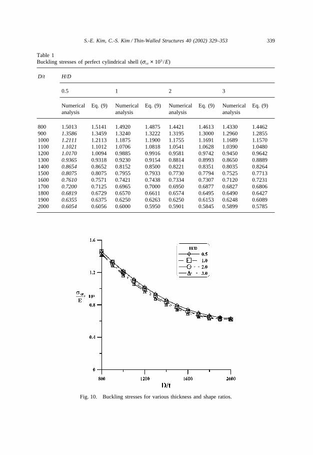
2.2.3. Parametric studyBuckling stresses were evaluated for cylindrical shells with diameter-to-thickness
ratio ranging from 800 to 2000 and height-to-diameter ratio from 0.5 to 3. Materialproperties used were the same as before. The buckling stresses corresponding to thevarious diameter-to-thickness and height-to-diameter ratios are presented as the ratioof buckling stress to elastic modulus in Table 1. The axisymmetric buckling mode(i.e. n � 0, m � �) occurred in the italicized area in Table 1. Their buckling stresseswere almost the same as the theoretical ones calculated by Eq. (7). The m and ntype buckling mode occurred in the non-italicized area in Table 1 and their bucklingstresses are very close to theoretical ones obtained by Eq. (4). Figs. 10 and 11 showthe buckling stresses with respect to the various diameter-to-thickness and height-to-diameter ratios. The buckling stress decreases significantly as the diameter-to-
Fig. 6. First mode shape of cylindrical shell (m � 1, n � 5).
337S.-E. Kim, C.-S. Kim / Thin-Walled Structures 40 (2002) 329–353
Fig. 7. Second mode shape of cylindrical shell (m � 3, n � 9).
thickness ratio increases (Fig. 10), while the buckling stress decreases slightly as theheight-to-diameter ratio increases (Fig. 11). These trends are different from those inthe case of columns. This is because buckling of a cylindrical shell is governed bynot only the axial buckling mode (m) but also the circumferential buckling mode(n). The number of half-waves in the circumferential direction (n) decreases as theheight-to-diameter ratio increases.
2.2.4. Design equationA design equation estimating the buckling strength of geometrically perfect cylin-
drical shells was developed by using regression analysis on the results in Table 1.The following design equation predicts buckling strength accurately with approxi-mately 1% errors:
scr
E� 1.19�H
D��0.0256 tD
. (9)
3. Geometrically perfect cylindrical tank
The cylindrical tank, i.e. the cylindrical shell with a bottom plate, was studied.Since a theoretical solution could not be obtained due to its complexity, numerical

338 S.-E. Kim, C.-S. Kim / Thin-Walled Structures 40 (2002) 329–353
Fig. 8. Third mode shape of cylindrical shell (m � 5, n � 11).
Fig. 9. Axisymmetric buckling mode shape.
339S.-E. Kim, C.-S. Kim / Thin-Walled Structures 40 (2002) 329–353
Table 1Buckling stresses of perfect cylindrical shell (scr × 103 /E)
D/t H/D
0.5 1 2 3
Numerical Eq. (9) Numerical Eq. (9) Numerical Eq. (9) Numerical Eq. (9)analysis analysis analysis analysis
800 1.5013 1.5141 1.4920 1.4875 1.4421 1.4613 1.4330 1.4462900 1.3586 1.3459 1.3240 1.3222 1.3195 1.3000 1.2960 1.28551000 1.2111 1.2113 1.1875 1.1900 1.1755 1.1691 1.1689 1.15701100 1.1021 1.1012 1.0706 1.0818 1.0541 1.0628 1.0390 1.04801200 1.0170 1.0094 0.9885 0.9916 0.9581 0.9742 0.9450 0.96421300 0.9365 0.9318 0.9230 0.9154 0.8814 0.8993 0.8650 0.88891400 0.8654 0.8652 0.8152 0.8500 0.8221 0.8351 0.8035 0.82641500 0.8075 0.8075 0.7955 0.7933 0.7730 0.7794 0.7525 0.77131600 0.7610 0.7571 0.7421 0.7438 0.7334 0.7307 0.7120 0.72311700 0.7200 0.7125 0.6965 0.7000 0.6950 0.6877 0.6827 0.68061800 0.6819 0.6729 0.6570 0.6611 0.6574 0.6495 0.6490 0.64271900 0.6355 0.6375 0.6250 0.6263 0.6250 0.6153 0.6248 0.60892000 0.6054 0.6056 0.6000 0.5950 0.5901 0.5845 0.5899 0.5785
Fig. 10. Buckling stresses for various thickness and shape ratios.

340 S.-E. Kim, C.-S. Kim / Thin-Walled Structures 40 (2002) 329–353
Fig. 11. Buckling stress for various shape and thickness ratios.
analysis was used. The numerical model was the same as that in the case of thegeometrically perfect shell, except that the bottom plate was also being modeled. Ahalf-model consisting of element type S8R was used. The numbers of elements usedwere 32 in the circumferential and 40 in the axial direction. The material propertiesused were the same as those previously. The effect of the soft and the stiff foundationshown in Figs. 12 and 13 was studied.
Fig. 12. Tank on soft foundation.

341S.-E. Kim, C.-S. Kim / Thin-Walled Structures 40 (2002) 329–353
Fig. 13. Tank on stiff foundation.
3.1. Soft foundation
The extremely soft foundation was assumed to get a lower-bound buckling strengthof the cylindrical tank. The ideal boundary condition was modeled by simple supportsat the nodal points on the circumferential edges of the tank bottom. Parametric studieswere performed for tanks with diameter-to-thickness ratio ranging from 800 to 2000and height-to-diameter ratio ranging from 0.5 to 3. Identical thicknesses of the wall(tw) and bottom plate (tb) were used. The buckling stresses are listed in Table 2.
The buckling strength of the perfect cylindrical tank on the soft foundationincreased by up to 1.6% compared with the cylindrical shell. Thus, the same designequation [Eq. (9)] can be used in estimating the buckling strength of the geometri-cally perfect tank placed on a soft foundation.
3.2. Stiff foundation
The extremely stiff foundation was assumed to get an upper-bound bucklingstrength. The ideal boundary condition was modeled by simple supports at the nodal
Table 2Buckling stresses of perfect cylindrical tank on soft foundation (scr × 103 /E)
D/t H/D
0.5 1 2 3
800 1.5192 1.5155 1.4551 1.43511100 1.1022 1.0958 1.0702 1.04561400 0.8659 0.8648 0.8353 0.80461700 0.7203 0.7134 0.7025 0.68982000 0.6061 0.6031 0.6005 0.5905

342 S.-E. Kim, C.-S. Kim / Thin-Walled Structures 40 (2002) 329–353
points on the circumferential edges as well as on the bottom plate. The ranges of thediameter-to-thickness and height-to-diameter ratios studied were the same as before.Identical thicknesses of the wall (tw) and bottom plate (tb) were used. The calculatedbuckling stresses are listed in Table 3. The buckling strength of the perfect tankplaced on the stiff foundation increased by a maximum of 5.6% compared with thaton the soft foundation.
A design equation for estimating buckling strength of the geometrically perfectcylindrical tank was developed by using regression analysis on the results listed inTable 3. The following design equation predicts the buckling strength with sufficientaccuracy within approximately 1% error:
scr
E� 1.28�H
D��0.0256 tD
. (10)
4. Geometrically imperfect cylindrical shell
This section examines the buckling stress of the geometrically imperfect cylindri-cal shell. The load–defection analysis was used.
4.1. Analysis method
The load–deflection analysis method accounts for initial geometric imperfections,which could be determined by a linear superposition of buckling eigenmodes. Theinitial geometric imperfection is expressed in the following form:
�xi � �i � 0
M
wi�i, (11)
where �i is the ith mode shape and wi is the associated scale factor.Non-linear static analysis, including both material and geometric non-linearity,
Table 3Buckling stresses of perfect cylindrical tank on stiff foundation (scr × 103 /E)
D/t H/D
0.5 1 2 3
800 1.5353 1.5192 1.5135 1.51301100 1.1133 1.1042 1.1010 1.09051400 0.8737 0.8676 0.8650 0.83401700 0.7243 0.7151 0.7132 0.70072000 0.6107 0.6078 0.6060 0.6056

343S.-E. Kim, C.-S. Kim / Thin-Walled Structures 40 (2002) 329–353
was used to obtain the ultimate load capacity. The Newton–Raphson solution tech-nique and default convergence tolerances were used for non-linear analyses.
4.2. Analysis model
The numerical model is the same as that in the case of the geometrically perfectshell. The half-model with element type S8R was used. Simply supported and sym-metric boundary conditions were used for the bottom and the top, respectively. Thenumbers of elements used were 32 in the circumferential and 40 in the axial direction.The material properties were the same as those used previously. The parametricstudies were performed for diameter-to-thickness ratios of 800, 1400 and 2000 andfor height-to-diameter ratio from 0.5 to 3. The first buckling mode shape obtainedby eigenvalue analysis was used as the initially imperfect shape of the shell. Theratio of the magnitude of initial imperfection to wall thickness (d0 / t) varied from 0to 3.
4.3. Analysis results
Cylindrical shell structures, in general, are very sensitive to the amplitude of theinitial geometric imperfection. The buckling stresses associated with the differentdiameter-to-thickness and height–diameter ratios, and the magnitudes of initialimperfection, are presented as the ratio of buckling stress to elastic modulus in Table4 and Figs. 14–17. It was observed that the cylindrical shells with the axisymmetricbuckling mode were much more sensitive to initial imperfection than those with thenon-axisymmetric buckling mode. The buckling strength of a geometrically imperfectcylindrical shell can be estimated by linear interpolation using the data in Table 4and Figs. 14–17.
5. Geometrically imperfect cylindrical tank
This section examines the buckling stress of the geometrically imperfect cylindri-cal tank. The load–deflection analysis was used. The initial geometric imperfectionscould be determined by a linear superposition of buckling eigenmodes. The numeri-cal model was the same as in the case of the geometrically perfect tank, except forthe geometric imperfections being modeled. Parametric studies were performed fortanks with diameter-to-thickness ratios of 800, 1400 and 2000 and height-to-diameterratio ranging from 0.5 to 3. The first buckling mode shape obtained by eigenvalueanalysis was used as the initially imperfect shape of the tank. The ratios of themagnitude of initial imperfection to wall thickness (d0 / t) varied from 0 to 3.
5.1. Soft foundation
The buckling stresses of the geometrically imperfect cylindrical tank placed onthe soft foundation are presented with respect to the imperfection ratio (d0 / t) in Table

344 S.-E. Kim, C.-S. Kim / Thin-Walled Structures 40 (2002) 329–353
Table 4Buckling stresses of geometrically imperfect shell (scr × 103 /E)
H/D d0/t D/t
800 1400 2000
0.5 0.0 1.5013 0.8654 0.60540.1 0.9223 0.6029 0.45840.3 0.6145 0.4673 0.34891.0 0.3446 0.2461 0.18582.0 0.2803 0.2127 0.15083.0 0.2564 0.2015 0.1377
1.0 0.0 1.4912 0.8152 0.60400.1 1.9000 0.5405 0.39230.3 0.8270 0.4349 0.30611.0 0.5266 0.2436 0.16582.0 0.4127 0.1985 0.13873.0 0.3343 0.1785 0.1235
2.0 0.0 1.4421 0.8221 0.59011.0 1.0395 0.6233 0.33842.0 0.8530 0.5315 0.28243.0 0.7252 0.4584 0.2535
3.0 0.0 1.4330 0.8035 0.58991.0 1.1108 0.5386 0.29052.0 0.9631 0.4490 0.21403.0 0.8458 0.4012 0.1913
5 and Figs. 18–21. It was observed that the tanks with the axisymmetric bucklingmode were more sensitive to initial imperfection than those with the non-axisym-metric buckling mode. The buckling strength of a geometrically imperfect tankplaced on a soft foundation can be estimated by linear interpolation using the datain Table 5 and Figs. 18–21.
5.2. Stiff foundation
The buckling stresses of the imperfect tank placed on the stiff foundation arepresented with respect to the imperfection ratio (d0 / t) in Table 6 and Figs. 22–25.The buckling strength of a geometrically imperfect cylindrical tank placed on a stifffoundation can be estimated by linear interpolation using the data in Table 6 andFigs. 22–25.
6. Conclusions
This paper studied the buckling strength of the cylindrical shell and tank subjectedto axially compressive loads. The conclusions are as follows.

345S.-E. Kim, C.-S. Kim / Thin-Walled Structures 40 (2002) 329–353
Fig. 14. Buckling stresses of imperfect shell (H /D � 0.5).
Fig. 15. Buckling stresses of imperfect shell (H /D � 1.0).

346 S.-E. Kim, C.-S. Kim / Thin-Walled Structures 40 (2002) 329–353
Fig. 16. Buckling stresses of imperfect shell (H /D � 2.0).
Fig. 17. Buckling stresses of imperfect shell (H /D � 3.0).

347S.-E. Kim, C.-S. Kim / Thin-Walled Structures 40 (2002) 329–353
Table 5Buckling stresses of geometrically imperfect tank on soft foundation (scr × 103 /E)
H/D d0/t D/t
800 1400 2000
0.5 0.0 1.5126 0.8664 0.60590.1 0.9938 0.6384 0.40580.3 0.6461 0.4560 0.34380.5 0.4933 0.3673 0.28801.0 0.3816 0.2800 0.22191.5 0.3517 0.2584 0.20012.0 0.3333 0.2498 0.18362.5 0.3176 0.7408 0.17573.0 0.3098 0.2362 0.1644
1.0 0.0 1.4912 0.8578 0.60400.1 0.9282 0.5686 0.40290.3 0.5747 0.4021 0.30140.5 0.4576 0.3170 0.24271.0 0.3645 0.2626 0.20011.5 0.3421 0.2299 0.18162.0 0.3261 0.2186 0.16772.5 0.3125 0.2058 0.15493.0 0.3018 0.1997 0.1499
2.0 0.0 1.4568 0.8369 0.59200.5 1.2880 0.7328 0.50641.0 1.1200 0.6480 0.44771.5 1.0030 0.5701 0.38492.0 0.8848 0.5024 0.33312.5 0.7728 0.4381 0.29173.0 0.6995 0.3888 0.2757
3.0 0.0 1.4330 0.8035 0.58990.5 1.2224 0.7060 0.46101.0 1.1002 0.6506 0.38181.5 1.0237 0.5811 0.32722.0 0.9502 0.5526 0.27922.5 0.9024 0.5347 0.24673.0 0.8518 0.5150 0.285
1. When elements S4R and S4R5 are used, the buckling stresses are overestimatedeven though a sufficient number of elements is used. When element type S8R isused, the buckling stresses are very close to those calculated from the analyticalequation within an error of 1.4%.
2. When a full model is used, ABAQUS does not predict buckling mode and buck-ling strength accurately. When a half-model in height with symmetric boundarycondition is used, ABAQUS can predict accurate buckling mode and strength.
3. The axisymmetric buckling mode (n � 0, m � �) occurs when the height-to-diameter ratio is less than 0.5 and the diameter-to-thickness ratio is greater than

348 S.-E. Kim, C.-S. Kim / Thin-Walled Structures 40 (2002) 329–353
Fig. 18. Buckling stresses of imperfect tank on soft foundation (H /D � 0.5).
Fig. 19. Buckling stresses of imperfect tank on soft foundation (H /D � 1.0).

349S.-E. Kim, C.-S. Kim / Thin-Walled Structures 40 (2002) 329–353
Fig. 20. Buckling stresses of imperfect tank on soft foundation (H /D � 2.0).
Fig. 21. Buckling stresses of imperfect tank on soft foundation (H /D � 3.0).

350 S.-E. Kim, C.-S. Kim / Thin-Walled Structures 40 (2002) 329–353
Table 6Buckling stresses of geometrically imperfect tank on stiff foundation (scr × 103 /E)
H/D d0/t D/t
800 1400 2000
0.5 0.0 1.5353 0.8737 0.61070.1 1.0701 0.7028 0.52480.3 0.7928 0.5626 0.38531.0 0.5034 0.3824 0.28842.0 0.4413 0.3224 0.24263.0 0.3952 0.2875 0.2045
1.0 0.0 1.5192 0.8676 0.60780.1 1.0191 0.5494 0.41270.3 0.7225 0.4655 0.31591.0 0.4501 0.3042 0.22082.0 0.4106 0.2732 0.19923.0 0.3873 0.2536 0.1782
2.0 0.0 1.5135 0.8650 0.60600.1 0.9208 0.6011 0.44330.3 0.6359 0.4602 0.33121.0 0.4698 0.2836 0.19442.0 0.3893 0.2604 0.17833.0 0.3495 0.2265 0.1576
3.0 0.0 1.5130 0.8340 0.60561.0 0.6522 0.6528 0.20182.0 0.5207 0.5743 0.15643.0 0.4902 0.5084 0.1233
900. The buckling stress of these shells can be calculated by Eq. (7). The othershells can be calculated by Eq. (4).
4. The buckling stresses decrease significantly as the diameter-to-thickness ratioincreases, while they decrease slightly as the height-to-diameter ratio increases.These trends are different from those of columns.
5. The buckling strength of the perfect tank placed on an extremely soft foundationand a stiff foundation increases by up to 1.6% and 5.6%, respectively, comparedwith that of the perfect shell.
6. Buckling strength decreases significantly as the amplitude of initial geometricimperfection increases. The cylindrical shells and tanks with the axisymmetricbuckling mode are more sensitive to initial imperfection than those with the non-axisymmetric buckling mode.
7. Convenient and sufficiently accurate design equations to use in estimating buck-ling strength of the perfect shell and tank are developed.
8. The buckling strength of the geometrically imperfect shell and tank can be esti-mated by linear interpolation using data in Tables 4–6 and Figs. 14–25.
9. The lower- and upper-bound buckling strength of the tank, corresponding toextremely soft and stiff foundations, is also provided.

351S.-E. Kim, C.-S. Kim / Thin-Walled Structures 40 (2002) 329–353
Fig. 22. Buckling stresses of imperfect tank on stiff foundation (H /D � 0.5).
Fig. 23. Buckling stresses of imperfect tank on stiff foundation (H /D � 1.0).

352 S.-E. Kim, C.-S. Kim / Thin-Walled Structures 40 (2002) 329–353
Fig. 24. Buckling stresses of imperfect tank on stiff foundation (H /D � 2.0).
Fig. 25. Buckling stresses of imperfect tank on stiff foundation (H /D � 3.0).

353S.-E. Kim, C.-S. Kim / Thin-Walled Structures 40 (2002) 329–353
Acknowledgements
This work was supported by grant no. 1999-1-311-001-3 from the InterdisciplinaryResearch Program of the KOSEF in Korea.
References
[1] Goto Y, Shang C. Plastic buckling transition modes in moderately thick cylindrical shells. J EngMech 1999;125(4):426–34.
[2] Mandara A, Mazzolani M. Stocky cylinders if compression: postcritical path evaluation and collapseload prediction with ABAQUS. In: Proceedings of ABAQUS User’s Conference, Archen, Germany1993; 421–35.
[3] Kim YS, Kardomateas GA. Buckling of thick orthotropic cylindrical shells under torsion. J ApplMech 1999;66:41–50.
[4] Chryssanthopulos MK, Baker MJ, Dowling PJ. Imperfection modeling for buckling analysis of stiff-ened cylinders. J Struct Eng 1991;117(7):1998–2017.
[5] Soldatos KP. Mechanics of cylindrical shells with non-circular cross-section: a survey. J Appl MechRev 1999;52(8):237–74.
[6] Donnell LH, Wan CC. Effect of imperfection on buckling of thin cylinders and columns under axialcompression. J Appl Mech 1950;17:73–83.
[7] Miller CD. Buckling of axially compressed cylinder. Proc ASCE, J Struct Div1976;103(ST3):695–721.
[8] Singer J. On the importance of shell buckling experiments. J Appl Mech Rev 1999;52(6):17–25.[9] Melerski ES. Simple elastic analysis of axisymmetric cylindrical storage tank. J Struct Eng
1991;117(11):3239–60.[10] Peek R. Analysis of unanchored liquid storage tanks under lateral loads. Earthquake Eng Struct Dyn
1988;16:1087–100.[11] Lau DT, Zeng X. Generation and use of simplified uplift shape functions in unanchored cylindrical
tanks. J Pressure Vessel Technol 1996;118:278–86.[12] Malhotra PK. Uplifting analysis of base plates in cylindrical tanks. J Struct Eng 1994;120:3489–505.[13] Peek R, El-Bkaily M. Postbuckling behavior of unanchored steel tanks under lateral loads. J Pressure
Vessel Technol 1991;113:423–8.[14] Nam MH, Lee KH. Unsymmetrically loaded cylindrical tank on elastic foundation. J Eng Mech
2000;126:1257–61.[15] Timoshenko SP, Gere JM. Theory of elastic stability. New York: McGraw-Hill, 1983.[16] Timoshenko SP, Woinowsky-Krieger S. Theory of plate and shell. New York: McGraw-Hill, 1959.[17] ABAQUS/standard user’s manual version 5.8, vol. I. Pawtucket (RI): Hibbit, Karlsson and Sor-
ensen, 1998.[18] ABAQUS/standard example manual version 5.8, vol. I. Pawtucket (RI): Hibbit, Karlsson and Sor-
ensen, 1998.