build a 2x8 cnc machine - dozuki-guide … · introduction assembly overview the adt2 2x8 cnc...
TRANSCRIPT
Adt2
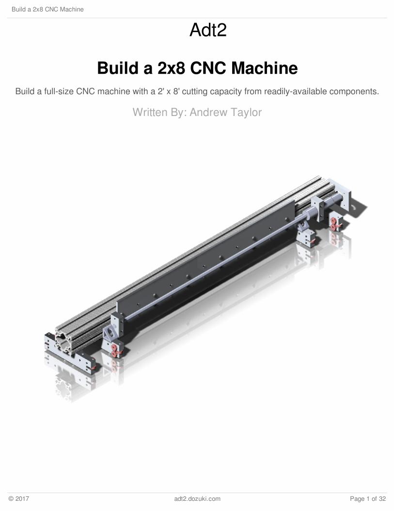
Build a 2x8 CNC MachineBuild a full-size CNC machine with a 2' x 8' cutting capacity from readily-available components.
Written By: Andrew Taylor
Build a 2x8 CNC Machine
© 2017 adt2.dozuki.com Page 1 of 32
INTRODUCTION
Assembly Overview
The ADT2 2x8 CNC Machine is a wood-and-aluminum machine intended primarily for machiningpatterns in thin sheet material such as plywood and MDF. While the machine will certainly becapable of performing heavier-duty work, my main goal is rather narrow in scope and the plans thatfollow have been based on that goal alone.
The machine itself is a hybrid design based on several different designs available online. The baseand table structure are based on the designs available at http://www.solsylva.com, and the rails,gantry, and Z-carriage are based on designs available at http://www.cncrouterparts.com (specificallythe 2x4 machine). This was my first CNC machine build, and much guidance and assistance camefrom the generous users at http://www.cnczone.com.
I'll document the installation, configuration, and tuning of the Mach3 software. Obviously my setupwill not be exactly like anyone else's, but after researching the various software options available andthe steps required to make said software functional, I feel a step-by-step guide tailored to thisparticular machine will be helpful.
A word of warning is probably in order about the size of the finished machine. Although the cuttingcapacity is roughly 2' x 8', the overall machine size is closer to 4' x 8'. The X-axis rail assemblies,rack-and-pinion drive components, and linear carriages that carry the gantry (Y-axis) eat up nearly afoot on each side of the machine. Plan your space accordingly.
Assembly Sequence
The X-Axis Rails
The X-axis rails are assembled first so the gantry's linear carriage assemblies can be adjustedproperly prior to their installation on the gantry.
The Gantry Assembly
The gantry must be assembled before the base can be built and the X-axis rails mounted becausetheir width is determined by the gantry's dimensions.
The Table Base
The table base is assembled and the X-axis rails are mounted when the gantry assembly iscomplete.
Build a 2x8 CNC Machine
© 2017 adt2.dozuki.com Page 2 of 32

The Z-Carriage Assembly
The Z-carriage is installed on the gantry after the gantry assembly has been installed on the X-axisrails.
Electronic Components
The various electronic components are installed and configured when the mechanical assembly iscomplete.
TOOLS:1/2" Open-End Wrench (1)
3/8" Drill Bit (1)
4' Level (1)
Center Punch (1)Various Sizes
Clamp (2)Various Sizes
Flat File (1)
Hammer (1)
Handheld Drill (1)Drill Press (optional)
Hex Wrench (1)Various Sizes
Marking Gauge (1)
Router (1)With Flush-Trim Bit
Square (1)
Table Saw (1)Circular Saw (optional)
Tape Measure (1)
Wood Glue (1)
PARTS:0.25" x 4" Aluminum Flat Bar (3)
2 @ 96", 1 @ 12"
5/16"-18 x 5/8" Button Head Cap Screws(48)
3030 T-Slot Extrusion (3)2 @ 96", 1 @ 48"
5/16"-18 3203 T-Nut (88)
Drilled and Counterbored Gear Rack (4)2 @ 54", 2 @ 42"
5/16"-18 x 7/8" Socket Head Cap Screws(40)
Extended Linear Carriage (6)All with tapped hole option
0.25" x 6" x 36" Aluminum Flat Bar (1)
Bearing Block and Cover (2)
1/2"-10 Acme Screw, 5-Start (1)1 @ 36.25"
1/2" Shaft Adapter (1)
1/2" Needle Thrust Bearing and Washers(2)
One-Piece Clamping Coupling (1)
1/2" Drill Rod (1)Cut to 2"
Zero-Backlash Helical Shaft Coupler (1)
5/16"-18 x 2-1/2" Carriage Bolt (8)
5/16"-18 Nylon Lock Nut (16)
4x4 (2)2 @ 96"
2x4 (9)
Build a 2x8 CNC Machine
© 2017 adt2.dozuki.com Page 3 of 32

2x4 (9)9 @ 96"
3" Wood Screws (1)1 Box
3/4" MDF (2)4x8 Sheets
5/16"-18 x 3-1/2" Carriage Bolt (8)
5/16" Fender Washer (8)
Rack and Pinion Drive, NEMA 23 (2)
Linear Carriage with ABEC 7 Bearings(2)
Build a 2x8 CNC Machine
© 2017 adt2.dozuki.com Page 4 of 32
Step 1 — Lay Out Mounting Holes on the 96" Flat Bars
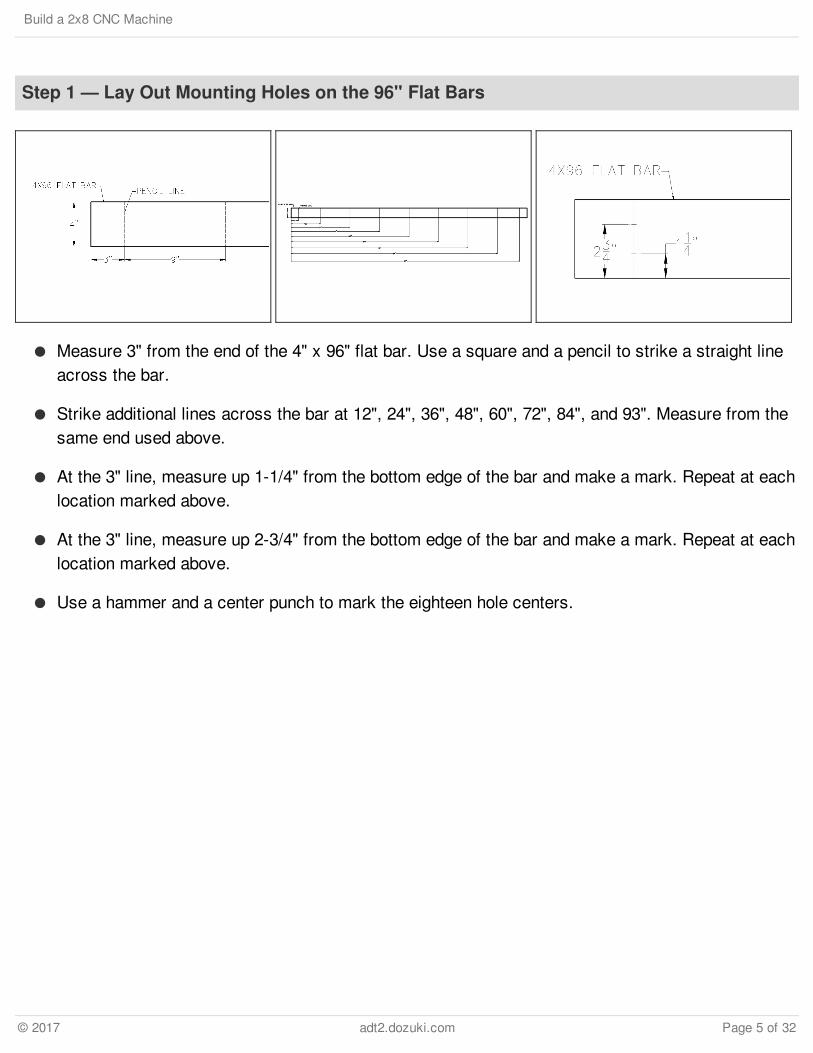
Measure 3" from the end of the 4" x 96" flat bar. Use a square and a pencil to strike a straight lineacross the bar.
Strike additional lines across the bar at 12", 24", 36", 48", 60", 72", 84", and 93". Measure from thesame end used above.
At the 3" line, measure up 1-1/4" from the bottom edge of the bar and make a mark. Repeat at eachlocation marked above.
At the 3" line, measure up 2-3/4" from the bottom edge of the bar and make a mark. Repeat at eachlocation marked above.
Use a hammer and a center punch to mark the eighteen hole centers.
Build a 2x8 CNC Machine
© 2017 adt2.dozuki.com Page 5 of 32
Step 2 — Drill Through-Holes in the 96" Flat Bars
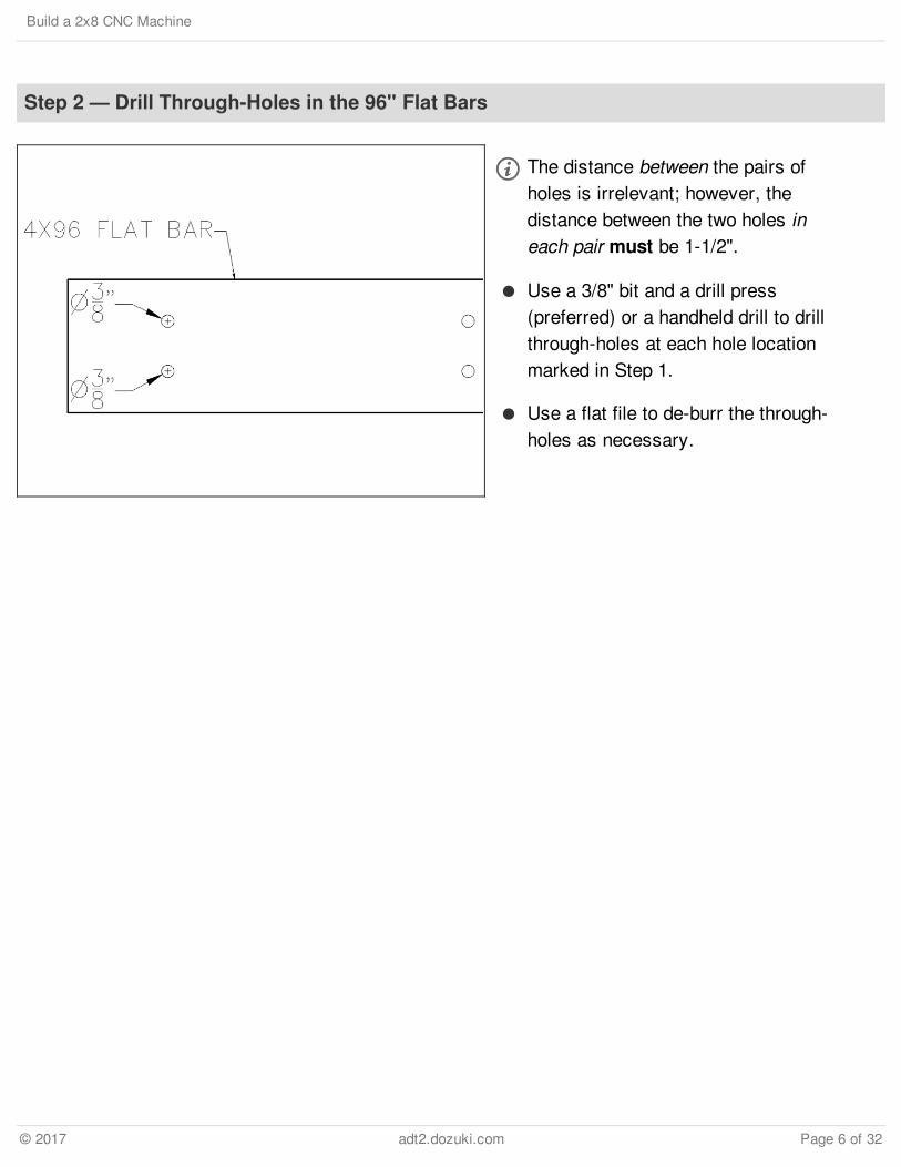
The distance between the pairs ofholes is irrelevant; however, thedistance between the two holes ineach pair must be 1-1/2".
Use a 3/8" bit and a drill press(preferred) or a handheld drill to drillthrough-holes at each hole locationmarked in Step 1.
Use a flat file to de-burr the through-holes as necessary.
Build a 2x8 CNC Machine
© 2017 adt2.dozuki.com Page 6 of 32
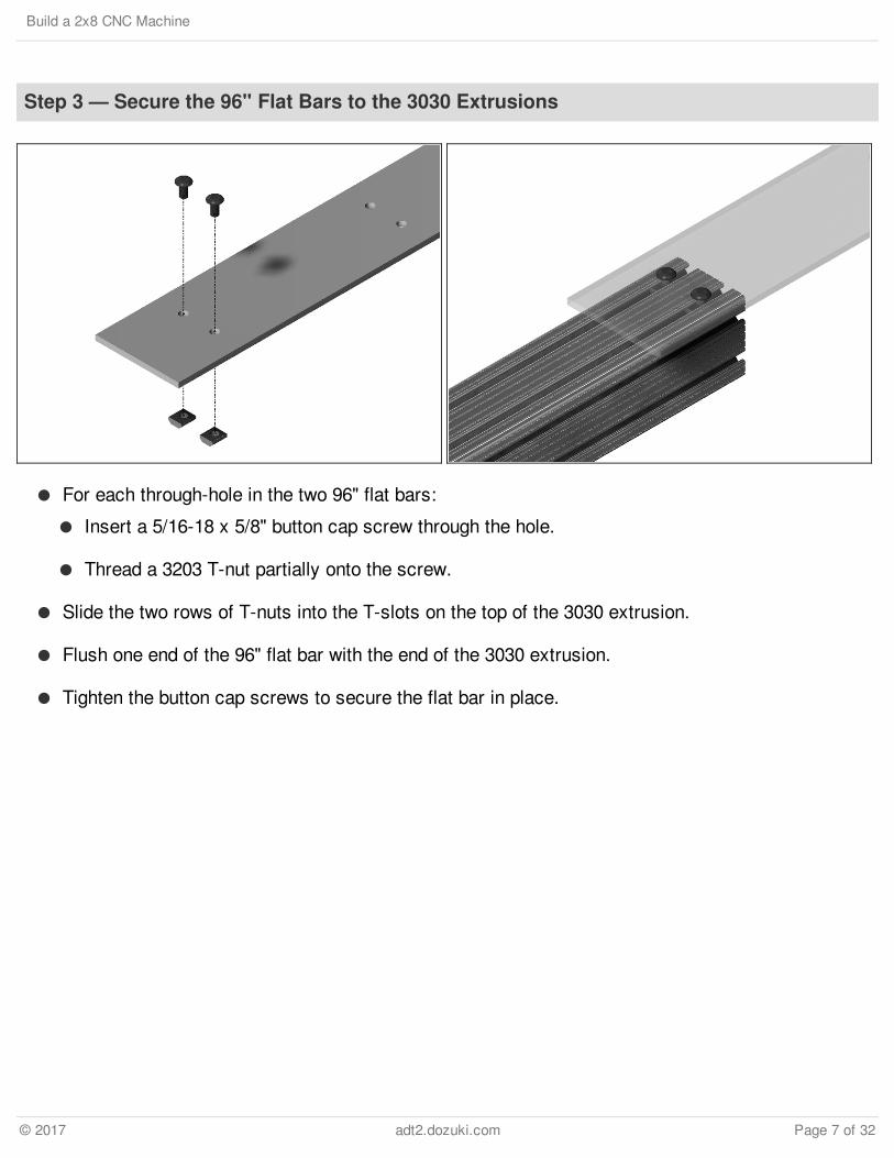
Step 3 — Secure the 96" Flat Bars to the 3030 Extrusions
For each through-hole in the two 96" flat bars:
Insert a 5/16-18 x 5/8" button cap screw through the hole.
Thread a 3203 T-nut partially onto the screw.
Slide the two rows of T-nuts into the T-slots on the top of the 3030 extrusion.
Flush one end of the 96" flat bar with the end of the 3030 extrusion.
Tighten the button cap screws to secure the flat bar in place.
Build a 2x8 CNC Machine
© 2017 adt2.dozuki.com Page 7 of 32

Step 4 — Install the Gear Racks on the 3030 Extrusions
Insert a 5/16-18 x 3/4" socket cap screw through each hole in one of the 54" gear racks, and threada 3203 T-nut partially onto each screw.
Slide the T-nuts into the bottom T-slot on the outside face of the 3030 extrusion. Flush the end ofthe rack with the end of the extrusion and tighten the screws.
One of the 42" lengths of gear rack should be identified as a "mate" to the 54" length of gear rackjust installed. Be sure you are installing the mating rack.
Insert a 5/16-18 x 3/4" socket cap screw through each hole on the mating 42" gear rack and threada 3203 T-nut partially onto each screw.
Slide the T-nuts into the T-slot until the short rack butts against the 54" rack. Ensure the tops of theracks are flush and tighten the screws.
Repeat this step to install the remaining 54" and 42" gear racks on the outside face of the other3030 extrusion.
Build a 2x8 CNC Machine
© 2017 adt2.dozuki.com Page 8 of 32
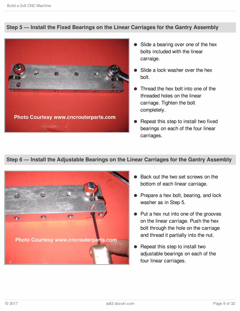
Step 5 — Install the Fixed Bearings on the Linear Carriages for the Gantry Assembly
Slide a bearing over one of the hexbolts included with the linearcarraige.
Slide a lock washer over the hexbolt.
Thread the hex bolt into one of thethreaded holes on the linearcarriage. Tighten the boltcompletely.
Repeat this step to install two fixedbearings on each of the four linearcarriages.
Step 6 — Install the Adjustable Bearings on the Linear Carriages for the Gantry Assembly
Back out the two set screws on thebottom of each linear carriage.
Prepare a hex bolt, bearing, and lockwasher as in Step 5.
Put a hex nut into one of the grooveson the linear carriage. Push the hexbolt through the hole on the carriageand thread it partially into the nut.
Repeat this step to install twoadjustable bearings on each of thefour linear carriages.
Build a 2x8 CNC Machine
© 2017 adt2.dozuki.com Page 9 of 32

Step 7 — Adjust the Linear Carriages
Each X-axis rail has two bearing surfaces: one outside and one inside. For the remainder of thisguide, the bearing surfaces and their respective linear carriages will be referred to as A, B, C, andD as shown in the figure.
Place one of the linear carriages onto bearing surface A with the adjustable bearings down. Tightenthe bolt on the first adjustable bearing. Slide the carriage back and forth along the rail. The motionshould be smooth without being tight. If the motion is too tight, back off the hex bolt just a hair.
Tighten the hex bolt on the remaining adjustable bearing and adjust it as above.
When both adjustable bearings are properly adjusted to the rail, slide the carriage off the end of therail and tighten the two set screws (loosened in Step 6). Do not over-tighten the screws.
Slide the carriage back onto the rail and make sure it still moves smoothly. Re-adjust the setscrews if necessary.
Remove the carriage from the rails and label it (A, B, C, or D) so it can be installed on the samebearing surface later.
Repeat this step to adjust both adjustable bearings on each of the three remaining linear carriagesto bearing surfaces B, C, and D.
Build a 2x8 CNC Machine
© 2017 adt2.dozuki.com Page 10 of 32

Step 8 — Lay Out Mounting Holes on the 36" Flat Bar
Cut the 6" x 36" flat bar to ??.??" long.
Measure 1" from the end of the flat bar. Use a square and a pencil to strike a straight line acrossthe bar.
Strike additional lines across the bar at 7", 13", 19", 25", and 31" from the end of the bar. Measurefrom the same end used above.
On the 1" line, measure up 2-1/4" from the bottom edge of the bar and make a mark. Repeat ateach location marked above.
On the 1" line, measure up 3-3/4" from the bottom edge of the bar and make a mark. Repeat ateach location marked above.
Use a hammer and a center punch to mark the twelve hole centers.
Build a 2x8 CNC Machine
© 2017 adt2.dozuki.com Page 11 of 32
Step 9 — Drill Through-Holes in the 6" Flat Bar
The distance between the pairs of holes is irrelevant; however, the distance between the two holesin each pair must be 1-1/2".
Use a 3/8" drill bit and a drill press (preferred) or a handheld drill to drill through-holes at each holelocation marked in Step 8.
Use a flat file to de-burr the through-holes as necessary.
Build a 2x8 CNC Machine
© 2017 adt2.dozuki.com Page 12 of 32

Step 10 — Assemble the Y-Axis Drive Components: Part 1
Assemble the two bearing blocks. Use the included screws to secure the covers to the blocks.
Insert one end of the ??" Acme screw into the 1/2" shaft adapter until fully seated. Tighten thescrews on the shaft adapter.
Slide a washer/needle thrust bearing/washer assembly over the 1/2" shaft adapter.
Slide one of the bearing blocks over the 1/2" shaft adapter with the cover facing away from theAcme screw.
Slide another washer/needle thrust bearing/washer assembly over the 1/2" shaft adapter.
Slide the one-piece clamping coupling over the 1/2" shaft adapter until fully seated. Tighten thescrews on the coupling.
Build a 2x8 CNC Machine
© 2017 adt2.dozuki.com Page 13 of 32
Step 11 — Assemble the Y-Axis Drive Components: Part 2
Cut a 2" length of 1/2" drill rod. Use sandpaper and/or a grinder to dress the rod ends asnecessary.
Insert the 2" length of drill rod into the one-piece clamping coupling until fully seated. Tighten thescrews on the clamping coupling.
Slide the zero-backlash helical shaft coupler over the exposed portion of the 2" length of drill roduntil fully seated. Tighten the screws on the coupler.
Build a 2x8 CNC Machine
© 2017 adt2.dozuki.com Page 14 of 32
Step 12 — Install Linear Carriage A on the Gantry
Insert two 5/16-18 x 2-1/2" carriage bolts through linear carriage A. Thread a lock nut loosely ontoeach bolt. Ensure the nuts are on the bottom side of the carriage (the same side as the setscrews).
Slide the carriage bolt heads into the T-slots on the bottom of the 3030 extrusion. Ensure thebearings are facing in.
Turn the 3030 extrusion over so the carriage is facing up. Tighten the lock nuts just until thecarriage is snug against the extrusion.
Slide the carriage over so the outside face of the carriage is exactly 1-1/4" from the end of the 3030extrusion. Use a square to ensure the carriage is perfectly square to the extrusion and then tightenthe two lock nuts.
Build a 2x8 CNC Machine
© 2017 adt2.dozuki.com Page 15 of 32

Step 13 — Install Linear Carriage B on the Gantry
Install two carriage bolts and lock nuts in linear carriage B as in Step 12 above.
Slide the bolt heads into the T-slots on the bottom of the gantry with the bearings facing out (towardlinear carriage A).
Slide carriage B toward carriage A until the inside faces are approximately 4-1/2" apart, and thentighten the two lock nuts just enough to hold carriage B in place.
Step 14 — Install the 6" Flat Bar
Insert one 5/16-18 x 5/8" button cap screw through each mounting hole on the 6" flat bar. Partiallythread a 3203 T-nut onto each screw.
Insert the two rows of T-nuts into the T-slots on the front face of the 3030 extrusion. Slide the flatbar over until the edge is approximately 1/4" from the inside face of linear carriage B and thentighten a few of the screws to secure the bar in place.
The remaining screws will be tightened later, after the carriages and drive components have beeninstalled and aligned.
Build a 2x8 CNC Machine
© 2017 adt2.dozuki.com Page 16 of 32

Step 15 — Install Linear Carriages C and D on the Gantry
Install two carriage bolts and lock nuts in linear carriages C and D as in Step 12 above.
Install linear carriage C:
Insert the two bolt heads into the T-slots on the bottom of the 3030 extrusion and slide thecarriage over until the inside face is approximately 1/4" from the edge of the 6" flat bar.
Tighten the bolts just enough to hold the carriage in place (it will be adjusted later).
Ensure the bearings face outside.
Install linear carriage D with the bearings facing inside.
Secure linear carriage D square to the 3030 extrusion with the outside face of the carriage 1" fromthe end of the extrusion.
Build a 2x8 CNC Machine
© 2017 adt2.dozuki.com Page 17 of 32

Step 16 — Install the Gantry on the X-Axis Rails
Ensure the X-axis rails are parallel, and then place the gantry on the rails. Ensure the carriages areoriented correctly (i.e. carriage A is mated with bearing surface A, etc.). This will likely take a fairbit of fiddling. The end goal is to have the X-axis rails supporting the gantry via carriages A and D(the two outside carriages; don't worry about carriages B and C just yet).
When the gantry is in place, carefully slide carriage B toward carriage A until the X-axis rail iscaptured between them. (A couple of clamps are helpful here, but don't torque them down too tight.)Tighten the lock nuts on the bottom of carriage B.
Repeat this Step to secure carriage C at the other end of the gantry.
Make sure the X-axis rails are still parallel, and then gently move the gantry back and forth. Itshould move easily along the rails without binding.
Measure the distance between the two outside faces of the X-axis rails (the 3030 extrusions - notthe gear racks). This is the table width. Make note of this distance somewhere.
Slide the gantry off the X-axis rails and set it aside.
Build a 2x8 CNC Machine
© 2017 adt2.dozuki.com Page 18 of 32

Step 17 — Cut the Table Legs to Length
Before starting, determine the desired finished height of the machine table.
The table legs are 3-3/4" shorter than the desired finished height of the work surface (torsion boxtop @ 3" plus 3/4" spoil board).
Mark the 4x4 table leg stock and cut four legs to length.
Step 18 — Cut the Upper and Lower Ladder Frame Members
Long Pieces:
Cut four (4) 2x4s to 96" long.
Medium Pieces:
Subtract 3" from the table width (see Step 16). Cut seven (7) pieces of 2x4 to this length.
Short Pieces:
Subtract 13" from the table width (see Step 16). Cut three (3) pieces of 2x4 to this length.
Build a 2x8 CNC Machine
© 2017 adt2.dozuki.com Page 19 of 32

Step 19 — Assemble the Upper Ladder Frame
Screw one of the 96" 2x4s to two legs. The top of the 2x4 should be flush with the top of the legs.The ends of the 2x4 should be flush with the outside faces of the legs.
Repeat the step above to screw a second 96" 2x4 to the two remaining legs.
Screw one of the medium-length 2x4s to the inside faces of the two legs at one end of the base.The top of the 2x4 should be flush with the tops of the legs.
Repeat the step above to screw a second medium-length 2x4 to the inside faces of the two legs atthe other end of the base.
Install three more medium-length 2x4s between the two 96" 2x4s at approximately 24" O.C.
Build a 2x8 CNC Machine
© 2017 adt2.dozuki.com Page 20 of 32
Step 20 — Assemble the Lower Ladder Frame
Turn the table base over so the legs are pointing up. Screw the two remaining 96" 2x4s to theoutside faces of the legs at a height suitable for a shelf. If any equipment will be mounted below thetable (such as an enclosure for the electronics), be sure to take the size of these items intoaccount when spacing the shelf.
Screw the two remaining medium-length 2x4s to the outside faces of the legs, flush with the twolower 96" 2x4s.
Install the three short 2x4s between the two lower 96" 2x4s. Space the 2x4s at approximately 24"O.C.
Build a 2x8 CNC Machine
© 2017 adt2.dozuki.com Page 21 of 32
Step 21 — Build the Torsion Box - Part 1
Turn the table base right-side-up. Verify that the outside-to-outside measurement of the table baseis the same as the table width measurement taken in Step 16.
Rip a sheet of 3/4" MDF to the table width.
Cross-cut the sheet of 3/4" MDF to 96" long.
Rip the 3/4" MDF off-cuts into 1-1/2" strips.
Lay the 3/4" MDF bottom skin on the table base. Flush the edges on all four sides.
Glue two 96" MDF strips to the bottom skin, flush with the outside edges and the ends.
Build a 2x8 CNC Machine
© 2017 adt2.dozuki.com Page 22 of 32
Step 22 — Build the Torsion Box - Part 2
Cut the remaining 1-1/2" MDF strips to fit between the two 96" strips glued to the bottom skin inStep 21.
Glue the 1-1/2" strips to the bottom skin between the two 96" strips. Make sure the two strips onthe ends are flush with the ends of the skin. Space the interior strips at about 16" O.C.
Mark on the outside of the two 96" strips where the cross-strips are installed. Screws will be driveninto the cross-strips from below later.
Cut the remaining MDF strips to fit between the cross-strips (15-1/4" long if the strips are installedat 16" O.C.).
Glue the short MDF strips between the cross-strips, down the centerline of the bottom skin.
Build a 2x8 CNC Machine
© 2017 adt2.dozuki.com Page 23 of 32

Step 23 — Build the Torsion Box - Part 3
When the glue has dried on all of the MDF strips, lay a bead of glue along the tops of all of thestrips.
Lay a second sheet of 3/4" MDF (the top skin) on top of the torsion box assembly, leaving a smalloverhang on all four sides. Weight the top skin down to ensure good contact between the matingsurfaces.
When the glue has dried, use a router with a flush-trim bit to flush the top skin to the torsion box.
Remember that the location of the interior cross-strips is marked on the outside faces of thetorsion box.
Make sure the torsion box is flush with the table frame on all four sides, and then drive 3" screwsat an angle through the 96" 2x4s and into the MDF cross-strips to secure the torsion box to thetable frame.
Build a 2x8 CNC Machine
© 2017 adt2.dozuki.com Page 24 of 32

Step 24 — Install the X-Axis Rails
Strike a line parallel to one of the long outside edges of the torsion box, 2-1/4" from the edge. (Usea marking gauge.)
Hook a tape measure to one end of the torsion box and mark hole centers on the 2-1/4" line at 6",34", 62", and 90" from the end of the table.
Drill 3/8" through-holes at each marked location. Drill through both the top and bottom skins of thetorsion box.
Slide four 3-1/2" carriage bolt heads into the inside T-slot (the slot opposite the gear racks) on thebottom of one of the X-axis rails. Lay the rail on its edge and move the bolts until they areapproximately in line with the through-holes.
Set the rail into place, aligning the carriage bolts with the through-holes. Ensure the outside edge ofthe 3030 extrusion is flush with the table edge, and secure each bolt with a washer and a lock nut.
Repeat this step to install the remaining X-axis rail on the other side of the table. Ensure the tworails are parallel before tightening the lock nuts.
Build a 2x8 CNC Machine
© 2017 adt2.dozuki.com Page 25 of 32
Step 25 — Install the Gantry
Hold the gantry at one end of the machine base. Make sure the carriages are mated with the properbearing surfaces (i.e. carriage A is aligned with bearing surface A, etc.).
Slide the gantry onto the X-axis rails.
If the table width measurement was taken correctly, and the table was built to the samedimension, the the gantry should slide right onto the rails.
If the gantry doesn't slide right onto the rails, loosen the two lock nuts securing carriage D,adjust the carriage as necessary, and then re-tighten the nuts.
Slide the gantry along the length of the rails; it should move smoothly from one end of the machineto the other.
If the gantry binds toward one end, then the rails are probably not installed parallel. Loosen thenuts underneath the table and adjust as necessary.
If the gantry binds at a random spot (or spots) along the rail and then moves smoothly again,then the flat bar is likely not straight and/or true. A power sander with 100-grit paper along thebearing surfaces will help.
Build a 2x8 CNC Machine
© 2017 adt2.dozuki.com Page 26 of 32
Step 26 — Square the Gantry to the X-Axis Rails
Move the gantry to one end of the machine. Use a pair of clamps to draw carriages A and Btogether, capturing the rail between them. (The nuts on carriage B should still be a hair loose.)
Tighten the lock nuts on the bottom of carriage B. Remove the clamps and make sure the gantrystill moves smoothly from one end of the machine to the other. If not, adjust carriage B asnecessary.
Put a large square on one of the X-axis rails near the end. Place a 4' level against the square.Clamp the level to both rails and remove the square.
Slide the gantry up against the level (it may be necessary to shim the front edge of the level so thecarriages can pass beneath it).
With the gantry held tight against the level, tighten the lock nuts on the bottom of carriage C.
Remove the level and make sure the gantry still moves smoothly along the rails. If not, adjustcarriage C as necessary.
Build a 2x8 CNC Machine
© 2017 adt2.dozuki.com Page 27 of 32

Step 27 — PENDING - Install the Rack-and-Pinion Drives
Assemble the pinion hardware.
Mount the pinion hardware to the outside of carriages A and D.
Tension the pinions against the racks.
Make sure the gantry is still square to the X-axis rails.
Build a 2x8 CNC Machine
© 2017 adt2.dozuki.com Page 28 of 32
Step 28 — PENDING - Assemble the Z-Carriage
Cut the 4" flat bar to length.
Lay out the mounting holes on the flat bar.
Drill through-holes in the flat bar.
Assemble the linear carriages and the router carriage.
Assemble the linear carriages and the Z-carriage.
Install the router carriage on the Z-carriage.
Install the Z-carriage on the gantry.
Step 29 — PENDING - Install Electronics
Install stepper motors.
Install cable carriers.
Build a 2x8 CNC Machine
© 2017 adt2.dozuki.com Page 29 of 32
Step 30 — Limit and Home Switches: Fabricate the Mounting Plates
Cut a 3" length of 1/8" x 1-1/2" x 1-1/2" aluminum angle. Use a flat file to de-burr the ends asnecessary.
Mark and drill two 3/8" holes on one leg of the angle. Center the holes in the leg, 3/8" and 1-7/8"down from the top edge of the angle.
Use a short length of tape or a dab of hot-melt glue to temporarily secure the limit switch to thebottom of the other (undrilled) leg of the angle. Flush the limit switch body (the black plastic part)with the front and bottom edges of the angle.
Use a center punch or a small nail to transfer the limit switch hole locations to the angle. Removethe switch from the angle.
Drill and tap two 4-40 holes for the limit switch.
Carefully ream out the two holes on the limit switch body so the 4-40 screws will go through themwithout being threaded.
Repeat this step to fabricate two more mounting plates.
Build a 2x8 CNC Machine
© 2017 adt2.dozuki.com Page 30 of 32
Step 31 — Limit and Home Switches: Fabricate the Receiver Plates
Cut a 2-5/8" length of 1/8" x 1-1/2" x 1-1/2" aluminum angle.
Drill a suitable mounting hole in one leg. HOW ARE YOU GOING TO MOUNT THIS IF END-USERIS USING 3030 FOR RAILS?
Drill and tap a hole for a 5/16-18 socket cap screw centered on the other (undrilled) leg.
Bolt the receiver plate to the X-axis rail.
Thread a 5/16-18 x 7/8" socket cap screw into the hole.
Build a 2x8 CNC Machine
© 2017 adt2.dozuki.com Page 31 of 32
This document was last generated on 2017-06-19 03:14:18 AM.
Step 32 — PENDING - Mach Software
Prepare the PC.
Install the software.
Test the software.
Configure the software.
Test the machine.
Build a 2x8 CNC Machine
© 2017 adt2.dozuki.com Page 32 of 32