build your own home security alarm system lesson … · build your own home security alarm system...
TRANSCRIPT
©2017. Stony Brook University. All rights reserved.
Build Your Own Home Security Alarm System
Lesson focus
Develop a home security alarm system that can help detect thieves. Students will be introduced
to different aspects of electrical engineering and relate it to physics concepts and engineering
design principles.
Lesson synopsis
Students should work in pairs. They will be provided with materials to build their own security
system. Once the team is done constructing the design, they will test the design in the testing
station.
Age level
Ages 13-18
Objectives
Students will be able to:
• Apply scientific knowledge to engineering design practices.
• Collaborate in building a device to meet a technological need.
• Develop and use a model that illustrates the relationships between components of a
system.
• Design, build, and refine an engineered product that works within given constraints to
convert one form of energy (chemical) to another (electrical).
• Relate the science concepts and engineering practices to college majors.
Anticipated outcomes
As a result of this activity students should develop an understanding of:
• Team work.
• Design concepts.
• Importance of technology.
• Electrical design.
Lesson Activities
Students design and build their own home security alarm systems from electrical components.
Students will be introduced to each component and learn its place within the subsystem of the
device. Students will also be able to take the designs with them to use them in their own homes.
©2017. Stony Brook University. All rights reserved.
Working in teams of two, students will communicate and assist one another to produce a finished
product.
Alignment to Curriculum Frameworks: See attached curriculum alignment sheet.
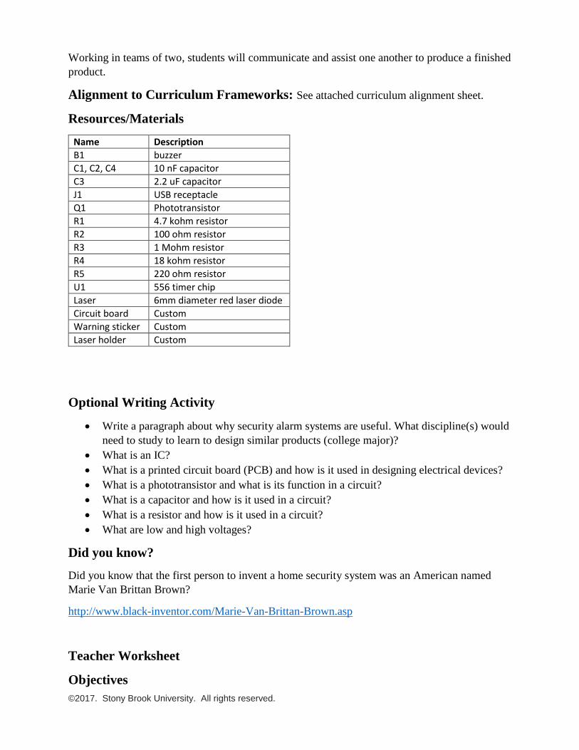
Resources/Materials
Name Description
B1 buzzer
C1, C2, C4 10 nF capacitor
C3 2.2 uF capacitor
J1 USB receptacle
Q1 Phototransistor
R1 4.7 kohm resistor
R2 100 ohm resistor
R3 1 Mohm resistor
R4 18 kohm resistor
R5 220 ohm resistor
U1 556 timer chip
Laser 6mm diameter red laser diode
Circuit board Custom
Warning sticker Custom
Laser holder Custom
Optional Writing Activity
• Write a paragraph about why security alarm systems are useful. What discipline(s) would
need to study to learn to design similar products (college major)?
• What is an IC?
• What is a printed circuit board (PCB) and how is it used in designing electrical devices?
• What is a phototransistor and what is its function in a circuit?
• What is a capacitor and how is it used in a circuit?
• What is a resistor and how is it used in a circuit?
• What are low and high voltages?
Did you know?
Did you know that the first person to invent a home security system was an American named
Marie Van Brittan Brown?
http://www.black-inventor.com/Marie-Van-Brittan-Brown.asp
Teacher Worksheet
Objectives
©2017. Stony Brook University. All rights reserved.
Student should learn the following after finishing this project
• Apply scientific knowledge to engineering design practices.
• Collaborate in building a device to meet a technological need.
• Develop and use a model that illustrates the relationships between components of a
system.
• Design, build, and refine an engineered product that works within given constraints to
convert one form of energy (chemical) to another (electrical).
• Relate the science concepts and engineering practices to college majors.
Outline 1. Introduction:
• Class should be divided into groups of two though each student will make her own
device.
• Materials should be distributed to each individual.
• Safety manual should be read and explained to students prior to implementation
(http://safety.eng.cam.ac.uk/procedures/Soldering/soldering-safety).
• Short movie or power point presentation should be presented if available.
2. Theory
• Explanation of the design parts (refer to the document or power point presentation
provided).
• Relate the theory of the design to the high school physics curriculum.
3. Implementation:
• Project implementation time (Students should follow the implementation section in
the Student Worksheet)
4. Break :
• Break – game – 30 mins
• Lunch in Student Activity Center – 30-45 mins
5. Theory and Implementation :
• Theory (refer to the document provided).
• Project Implementation (Students should continuing following the implementation
section in the Student Worksheet).
6. Testing:
• Testing (Students should follow the testing section in the Student Worksheet)
Although each student will build their own circuits, the classroom should be divided into
groups of two to foster team work. It is important that the teacher explains the advantage of the
team work for the class and allow students of the same group to help one another and develop
explanations for design functionality based on observations.
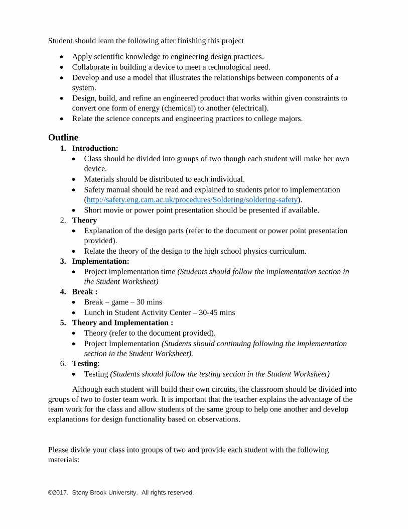
Please divide your class into groups of two and provide each student with the following
materials:
©2017. Stony Brook University. All rights reserved.
Name Description
B1 buzzer
C1, C2, C4 10 nF capacitor
C3 2.2 uF capacitor
J1 USB receptacle
Q1 Phototransistor
R1 4.7 kohm resistor
R2 100 ohm resistor
R3 1 Mohm resistor
R4 18 kohm resistor
R5 220 ohm resistor
U1 556 timer chip
Laser 6mm diameter red laser diode
Circuit board Custom
Warning sticker Custom
Laser holder Custom
The teacher must read and explain the safety manual to students before proceeding any
further with the project.
©2017. Stony Brook University. All rights reserved.
Safety Manual
No shorts, skirts, or any open shoes allowed in the lab. It is safer to wear 100% cotton
shirts before you start this lab.
• Secure long hair and loose clothing (especially loose long sleeves, neck ties, or scarves).
• Remove ALL jewelry.
• Synthetic fingernails, which are made of extremely flammable polymers, are not
recommended in the laboratory. Please make sure you don’t have synthetic finger nails
while soldering.
Laser light:
▪ Before turning on the laser pointer, always be sure that it is pointed away from yourself
and others.
▪ Never look directly into a laser pointer.
▪ Never direct a laser pointer at another person.
▪ Follow the same rules for direct reflections of laser light from reflective surfaces.
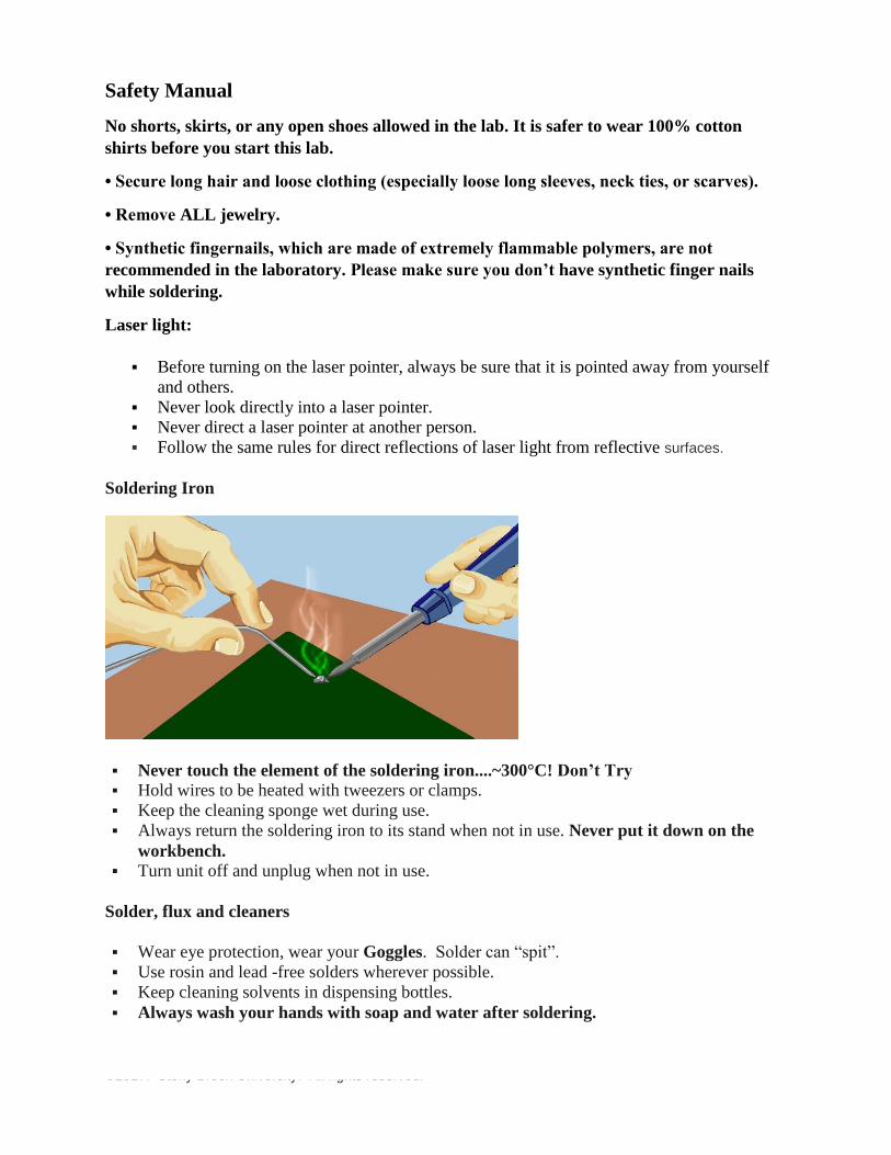
Soldering Iron
▪ Never touch the element of the soldering iron....~300°C! Don’t Try
▪ Hold wires to be heated with tweezers or clamps.
▪ Keep the cleaning sponge wet during use.
▪ Always return the soldering iron to its stand when not in use. Never put it down on the
workbench.
▪ Turn unit off and unplug when not in use.
Solder, flux and cleaners
▪ Wear eye protection, wear your Goggles. Solder can “spit”.
▪ Use rosin and lead -free solders wherever possible.
▪ Keep cleaning solvents in dispensing bottles.
▪ Always wash your hands with soap and water after soldering.
©2017. Stony Brook University. All rights reserved.
Lead exposure
▪ Lead can give rise to serious chronic health effects. Exposure will primarily be through
accidental ingestion from your skin, wear gloves if directly handling solder. Limited fumes
may be generated by soldering.
Control of Fumes
▪ Bench top filter extract systems may be used for rosin-free soldering in well ventilated areas
(i.e. large volume work space or with mechanical air changes. Placement of these is
important to performance, if in doubt ask.
▪ All extract systems should be tested at least annually and maintained (i.e. change filters
regularly). Keep a log of filter changes or mark date on filter/system.
▪ Do not solder if extract is not working properly and report immediately.
Training and Supervision
▪ Teachers should inform users of the risks from soldering.
▪ Teachers should ensure that controls are in place and working and that they are used
correctly.
▪ All those soldering should be trained and supervised appropriately.
Electrical Safety
▪ Do not use soldering irons that have obvious damage to body, cable or plug.
▪ All soldering irons should have had electrical safety (PAT) testing within the last twelve
months. If not, contact the on-site BOC representative.
▪ Keep the soldering station free of electrical cables to prevent damage from the heated tip.
▪ Use a grounded outlet and grounding prong if a short circuit is a possibility.
Fire Prevention
▪ Work on a fire-proof or fire resistant surface.
▪ Wear fire resistant clothing (e.g. 100% cotton) that covers your arms and legs to prevent
accidental burns.
▪ Know where your nearest fire extinguisher is and how to use it (Safety Office can arrange
training).
First Aid
▪ Immediate place any burns under cold water for 15 minutes.
▪ Report to a first aider if deep or extensive otherwise protect with a plaster (band-aid).

©2017. Stony Brook University. All rights reserved.
Waste
▪ Collect waste solder in a lidded container. Replace lid when not in use.
▪ Label appropriately and dispose of as hazardous waste (contact Safety Office).
▪ Used solder sponges and contaminated rags should be placed in a sealable bag for disposal
as hazardous waste.
The following safety instructions can be found at:
Soldering safety instructions:
http://safety.eng.cam.ac.uk/procedures/Soldering/soldering-safety
Laser safety instructions:
http://www.sciencebuddies.org/science-fair-projects/project_ideas/Phys_Laser_Safety.shtml

©2017. Stony Brook University. All rights reserved.
Student Worksheet
Have you ever thought about implementing your own home security alarm system? It is one of
the simplest and most interesting circuits for electrical engineering novices. Your new home
security equipment will use a phototransistor and timer to detect security problems. Theft attempt
and other security threats can be controlled by using this simple circuit. This circuit can be
implemented in your own private room or even your closet.
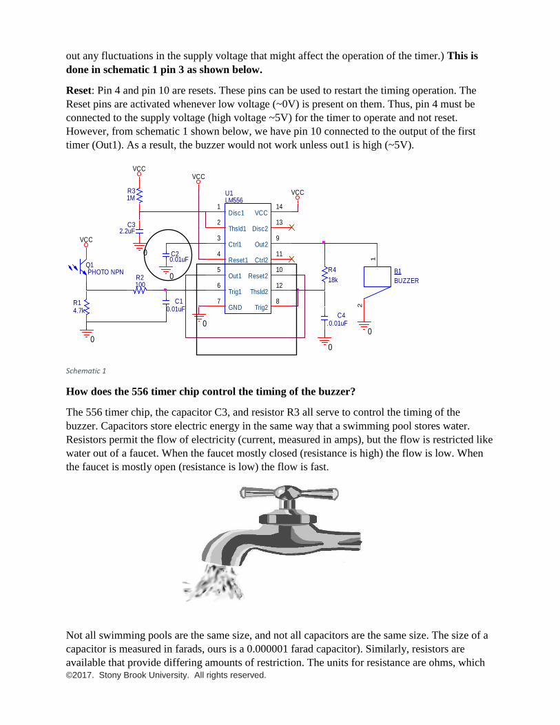
Circuit Diagram Of Home Security Alarm
Schematic 1
Components required:
Name Description
B1 buzzer
C1, C2, C4 10 nF capacitor
C3 2.2 uF capacitor
J1 USB receptacle
Q1 Phototransistor
R1 4.7 kohm resistor
R2 100 ohm resistor
R3 1 Mohm resistor
R4 18 kohm resistor
R5 220 ohm resistor
U1 556 timer chip
Laser 6mm diameter red laser diode
Circuit board Custom
Warning sticker Custom
Laser holder Custom
Theory
Circuit description
The circuit is a security system that buzzes when the light beam going through the circuit is
blocked as shown in the figure below. Blocking the light enables the buzzer and indicates a
security problem.
U1LM556
Disc11
Thsld12
Ctrl13
Reset14
Out15
Trig16
GND7
Trig28
Out29
Reset210
Ctrl211
Thsld212
Disc213
VCC14
0
VCC
Q1PHOTO NPN
R14.7k
R2100
C10.01uF
VCC
0
C20.01uF
0
R31M
C32.2uF
0
B1
BUZZER
1
2
0
R4
18k
C4.0.01uF
0
VCCVCC
©2017. Stony Brook University. All rights reserved.
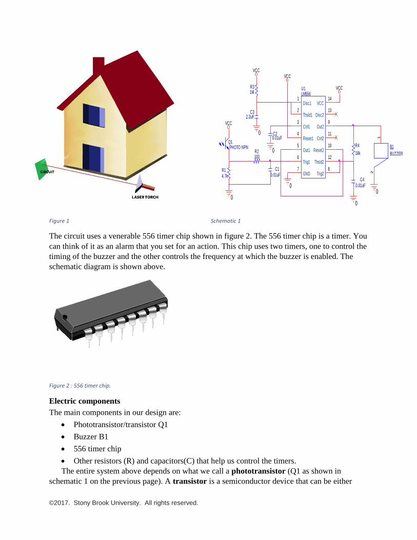
Figure 1 Schematic 1
The circuit uses a venerable 556 timer chip shown in figure 2. The 556 timer chip is a timer. You
can think of it as an alarm that you set for an action. This chip uses two timers, one to control the
timing of the buzzer and the other controls the frequency at which the buzzer is enabled. The
schematic diagram is shown above.
Figure 2 : 556 timer chip.
Electric components
The main components in our design are:
• Phototransistor/transistor Q1
• Buzzer B1
• 556 timer chip
• Other resistors (R) and capacitors(C) that help us control the timers.
The entire system above depends on what we call a phototransistor (Q1 as shown in
schematic 1 on the previous page). A transistor is a semiconductor device that can be either
U1LM556
Disc11
Thsld12
Ctrl13
Reset14
Out15
Trig16
GND7
Trig28
Out29
Reset210
Ctrl211
Thsld212
Disc213
VCC14
0
VCC
Q1PHOTO NPN
R14.7k
R2100
C10.01uF
VCC
0
C20.01uF
0
R31M
C32.2uF
0
B1
BUZZER
1
2
0
R4
18k
C4.0.01uF
0
VCCVCC
©2017. Stony Brook University. All rights reserved.
used as an amplifier of our signals or as a switch. In our design we will use the transistor Q1 as a
switch.
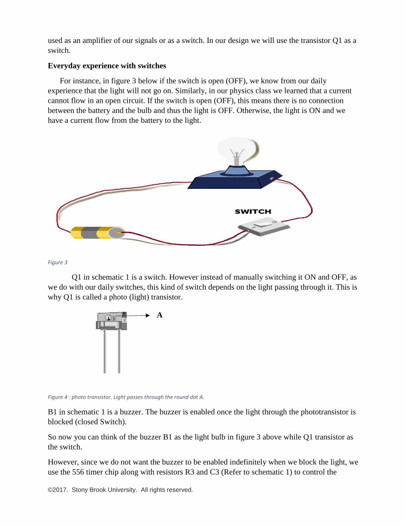
Everyday experience with switches
For instance, in figure 3 below if the switch is open (OFF), we know from our daily
experience that the light will not go on. Similarly, in our physics class we learned that a current
cannot flow in an open circuit. If the switch is open (OFF), this means there is no connection
between the battery and the bulb and thus the light is OFF. Otherwise, the light is ON and we
have a current flow from the battery to the light.
Figure 3
Q1 in schematic 1 is a switch. However instead of manually switching it ON and OFF, as
we do with our daily switches, this kind of switch depends on the light passing through it. This is
why Q1 is called a photo (light) transistor.
Figure 4 : photo transistor. Light passes through the round dot A.
B1 in schematic 1 is a buzzer. The buzzer is enabled once the light through the phototransistor is
blocked (closed Switch).
So now you can think of the buzzer B1 as the light bulb in figure 3 above while Q1 transistor as
the switch.
However, since we do not want the buzzer to be enabled indefinitely when we block the light, we
use the 556 timer chip along with resistors R3 and C3 (Refer to schematic 1) to control the
A
©2017. Stony Brook University. All rights reserved.
timing the buzzer will be enabled after the light is blocked. For our project, the buzzer will be
enabled for short time only.
Note that changing the values of R3 and C3 can change the timing the buzzer goes on for
(discussed in details in the following section).
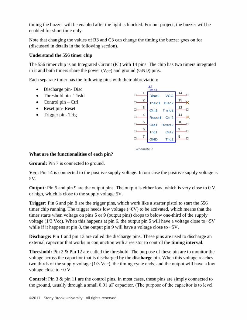
Understand the 556 timer chip
The 556 timer chip is an Integrated Circuit (IC) with 14 pins. The chip has two timers integrated
in it and both timers share the power (VCC) and ground (GND) pins.
Each separate timer has the following pins with their abbreviation:
• Discharge pin- Disc
• Threshold pin- Thsld
• Control pin – Ctrl
• Reset pin- Reset
• Trigger pin- Trig
Schematic 2
What are the functionalities of each pin?
Ground: Pin 7 is connected to ground.
VCC: Pin 14 is connected to the positive supply voltage. In our case the positive supply voltage is
5V.
Output: Pin 5 and pin 9 are the output pins. The output is either low, which is very close to 0 V,
or high, which is close to the supply voltage 5V.
Trigger: Pin 6 and pin 8 are the trigger pins, which work like a starter pistol to start the 556
timer chip running. The trigger needs low voltage (~0V) to be activated, which means that the
timer starts when voltage on pins 5 or 9 (output pins) drops to below one-third of the supply
voltage (1/3 Vcc). When this happens at pin 6, the output pin 5 will have a voltage close to ~5V
while if it happens at pin 8, the output pin 9 will have a voltage close to ~5V.
Discharge: Pin 1 and pin 13 are called the discharge pins. These pins are used to discharge an
external capacitor that works in conjunction with a resistor to control the timing interval.
Threshold: Pin 2 & Pin 12 are called the threshold. The purpose of these pin are to monitor the
voltage across the capacitor that is discharged by the discharge pin. When this voltage reaches
two thirds of the supply voltage (1/3 Vcc), the timing cycle ends, and the output will have a low
voltage close to ~0 V.
Control: Pin 3 & pin 11 are the control pins. In most cases, these pins are simply connected to
the ground, usually through a small 0.01 μF capacitor. (The purpose of the capacitor is to level
U2LM556
Disc11
Thsld12
Ctrl13
Reset14
Out15
Trig16
GND7
Trig28
Out29
Reset210
Ctrl211
Thsld212
Disc213
VCC14
©2017. Stony Brook University. All rights reserved.
out any fluctuations in the supply voltage that might affect the operation of the timer.) This is
done in schematic 1 pin 3 as shown below.
Reset: Pin 4 and pin 10 are resets. These pins can be used to restart the timing operation. The
Reset pins are activated whenever low voltage (~0V) is present on them. Thus, pin 4 must be
connected to the supply voltage (high voltage ~5V) for the timer to operate and not reset.
However, from schematic 1 shown below, we have pin 10 connected to the output of the first
timer (Out1). As a result, the buzzer would not work unless out1 is high (~5V).
Schematic 1
How does the 556 timer chip control the timing of the buzzer?
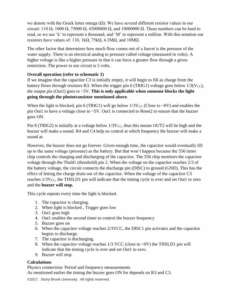
The 556 timer chip, the capacitor C3, and resistor R3 all serve to control the timing of the
buzzer. Capacitors store electric energy in the same way that a swimming pool stores water.
Resistors permit the flow of electricity (current, measured in amps), but the flow is restricted like
water out of a faucet. When the faucet mostly closed (resistance is high) the flow is low. When
the faucet is mostly open (resistance is low) the flow is fast.
Not all swimming pools are the same size, and not all capacitors are the same size. The size of a
capacitor is measured in farads, ours is a 0.000001 farad capacitor). Similarly, resistors are
available that provide differing amounts of restriction. The units for resistance are ohms, which
U1LM556
Disc11
Thsld12
Ctrl13
Reset14
Out15
Trig16
GND7
Trig28
Out29
Reset210
Ctrl211
Thsld212
Disc213
VCC14
0
VCC
Q1PHOTO NPN
R14.7k
R2100
C10.01uF
VCC
0
C20.01uF
0
R31M
C32.2uF
0
B1
BUZZER
1
2
0
R4
18k
C4.0.01uF
0
VCCVCC
©2017. Stony Brook University. All rights reserved.
we denote with the Greek letter omega (Ω). We have several different resistor values in our
circuit: 110 Ω, 1000 Ω, 75000 Ω, 43000000 Ω, and 10000000 Ω. These numbers can be hard to
read, so we use ‘k’ to represent a thousand, and ‘M’ to represent a million. With this notation our
resistors have values of: 110, 1kΩ, 75kΩ, 4.3MΩ, and 10MΩ.
The other factor that determines how much flow comes out of a faucet is the pressure of the
water supply. There is an electrical analog to pressure called voltage (measured in volts). A
higher voltage is like a higher pressure in that it can force a greater flow through a given
restriction. The power in our circuit is 5 volts.
Overall operation (refer to schematic 1)
If we imagine that the capacitor C3 is initially empty, it will begin to fill as charge from the
battery flows through resistors R3. When the trigger pin 6 (TRIG1) voltage goes below 1/3(VCC),
the output pin (Out1) goes to ~5V. This is only applicable when someone blocks the light
going through the phototransistor mentioned above.
When the light is blocked, pin 6 (TRIG1) will go below 1/3VCC (Close to ~0V) and enables the
pin Out1 to have a voltage close to ~5V. Out1 is connected to Reset2 to ensure that the buzzer
goes ON.
Pin 8 (TRIG2) is initially at a voltage below 1/3VCC, thus this means OUT2 will be high and the
buzzer will make a sound. R4 and C4 help us control at which frequency the buzzer will make a
sound at.
However, the buzzer does not go forever. Given enough time, the capacitor would eventually fill
up to the same voltage (pressure) as the battery. But that won’t happen because the 556 timer
chip controls the charging and discharging of the capacitor. The 556 chip monitors the capacitor
voltage through the Thsld1 (threshold) pin 2. When the voltage on the capacitor reaches 2/3 of
the battery voltage, the circuit connects the discharge pin (DISC) to ground (GND). This has the
effect of letting the charge drain out of the capacitor. When the voltage of the capacitor C3
reaches 1/3VCC, the THSLD1 pin will indicate that the timing cycle is over and set Out1 to zero
and the buzzer will stop.
This cycle repeats every time the light is blocked.
1. The capacitor is charging.
2. When light is blocked , Trigger goes low
3. Out1 goes high
4. Out1 enables the second timer to control the buzzer frequency
5. Buzzer goes on
6. When the capacitor voltage reaches 2/3VCC, the DISC1 pin activates and the capacitor
begins to discharge.
7. The capacitor is discharging.
8. When the capacitor voltage reaches 1/3 VCC (close to ~0V) the THSLD1 pin will
indicate that the timing cycle is over and set Out1 to zero.
9. Buzzer will stop
Calculations
Physics connection: Period and frequency measurements
As mentioned earlier the timing the buzzer goes ON for depends on R3 and C3.
©2017. Stony Brook University. All rights reserved.
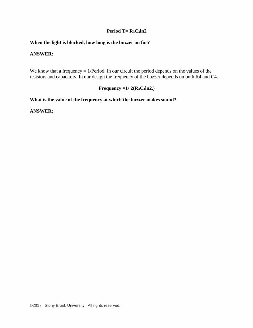
Period T= R3C3ln2
When the light is blocked, how long is the buzzer on for?
ANSWER:
We know that a frequency = 1/Period. In our circuit the period depends on the values of the
resistors and capacitors. In our design the frequency of the buzzer depends on both R4 and C4.
Frequency =1/ 2(R4C4ln2.)
What is the value of the frequency at which the buzzer makes sound?
ANSWER:
©2017. Stony Brook University. All rights reserved.
Implementation: Before proceeding, make sure you have read and understood the safety manual sheet for this
project. Otherwise, DO NOT proceed.
Please make sure you have the following materials:
Name Description
B1 buzzer
C1, C2, C4 10 nF capacitor
C3 2.2 uF capacitor
J1 USB receptacle
Q1 Phototransistor
R1 4.7 kohm resistor
R2 100 ohm resistor
R3 1 Mohm resistor
R4 18 kohm resistor
R5 220 ohm resistor
U1 556 timer chip
Laser 6mm diameter red laser diode
Circuit board Custom
Warning sticker Custom
Laser holder Custom
©2017. Stony Brook University. All rights reserved.
Orientation critical:
The following components must be installed in a particular direction. After installing the
component, solder it down and trim the leads if necessary.
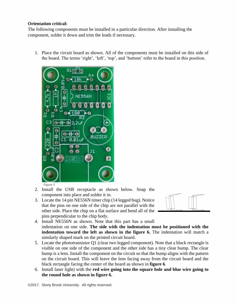
1. Place the circuit board as shown. All of the components must be installed on this side of
the board. The terms ‘right’, ‘left’, ‘top’, and ‘bottom’ refer to the board in this position.
Figure 5
2. Install the USB receptacle as shown below. Snap the
component into place and solder it in.
3. Locate the 14 pin NE556N timer chip (14 legged bug). Notice
that the pins on one side of the chip are not parallel with the
other side. Place the chip on a flat surface and bend all of the
pins perpendicular to the chip body.
4. Install NE556N as shown. Note that this part has a small
indentation on one side. The side with the indentation must be positioned with the
indentation toward the left as shown in the figure 6. The indentation will match a
similarly shaped mark on the printed circuit board.
5. Locate the phototransistor Q1 (clear two legged component). Note that a black rectangle is
visible on one side of the component and the other side has a tiny clear bump. The clear
bump is a lens. Install the component on the circuit so that the bump aligns with the pattern
on the circuit board. This will leave the lens facing away from the circuit board and the
black rectangle facing the center of the board as shown in figure 6.
6. Install laser light) with the red wire going into the square hole and blue wire going to
the round hole as shown in figure 6.
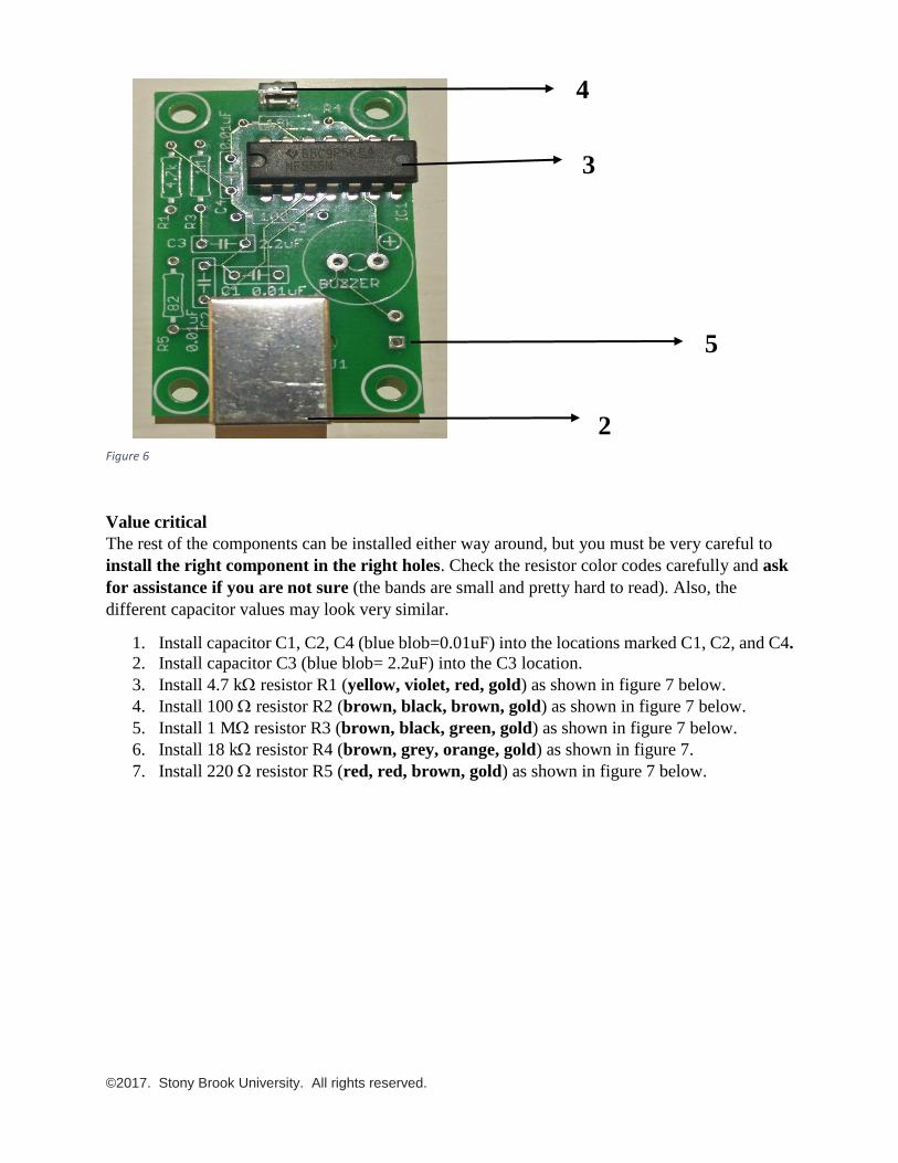
©2017. Stony Brook University. All rights reserved.
Figure 6
Value critical
The rest of the components can be installed either way around, but you must be very careful to
install the right component in the right holes. Check the resistor color codes carefully and ask
for assistance if you are not sure (the bands are small and pretty hard to read). Also, the
different capacitor values may look very similar.
1. Install capacitor C1, C2, C4 (blue blob=0.01uF) into the locations marked C1, C2, and C4.
2. Install capacitor C3 (blue blob= 2.2uF) into the C3 location.
3. Install 4.7 k resistor R1 (yellow, violet, red, gold) as shown in figure 7 below.
4. Install 100 resistor R2 (brown, black, brown, gold) as shown in figure 7 below.
5. Install 1 M resistor R3 (brown, black, green, gold) as shown in figure 7 below.
6. Install 18 k resistor R4 (brown, grey, orange, gold) as shown in figure 7.
7. Install 220 resistor R5 (red, red, brown, gold) as shown in figure 7 below.
4
3
2
5
©2017. Stony Brook University. All rights reserved.
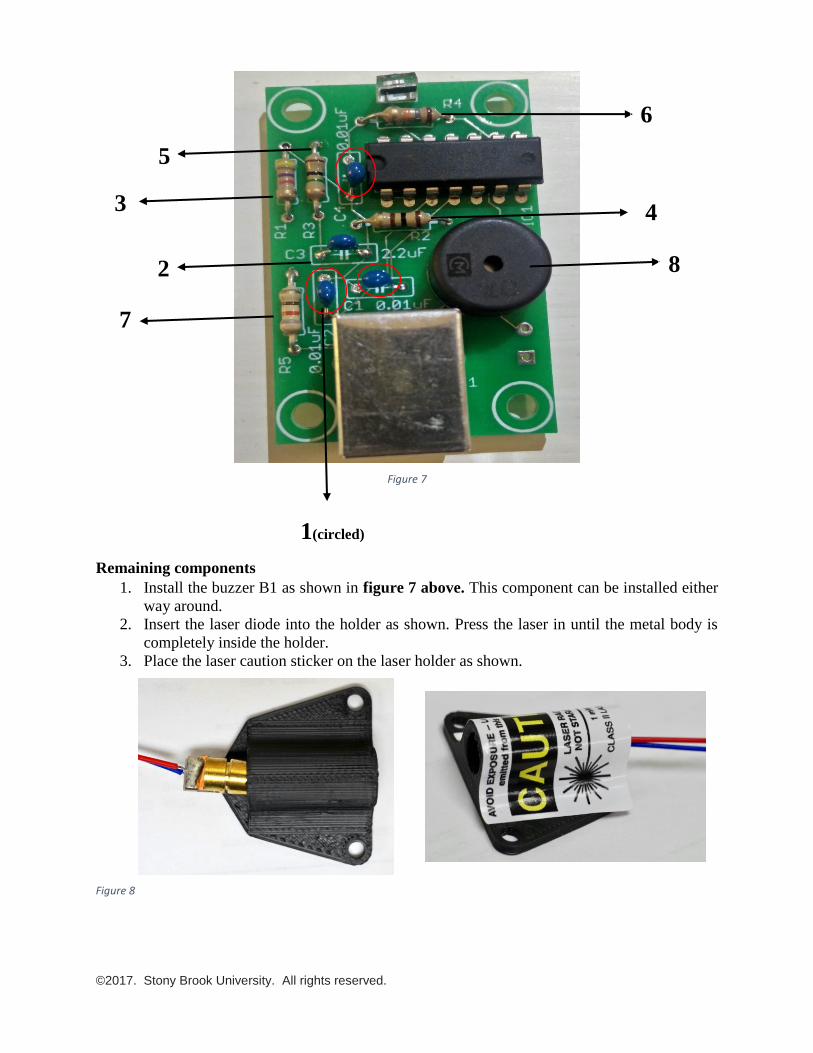
Figure 7
Remaining components
1. Install the buzzer B1 as shown in figure 7 above. This component can be installed either
way around.
2. Insert the laser diode into the holder as shown. Press the laser in until the metal body is
completely inside the holder.
3. Place the laser caution sticker on the laser holder as shown.
Figure 8
6
4
5
3
2
7
8
1(circled)
©2017. Stony Brook University. All rights reserved.
Project testing Power for this project can be provided by a USB charger or USB computer port. You will need a
cable with a USB type ‘B’ end to fit the receptacle. These cables are often used for wired
printers. To implement this alarm system for home/room, you have to provide an optical path
(with LASER beams) around your home/room. (You have implemented this laser already on
your PCB).
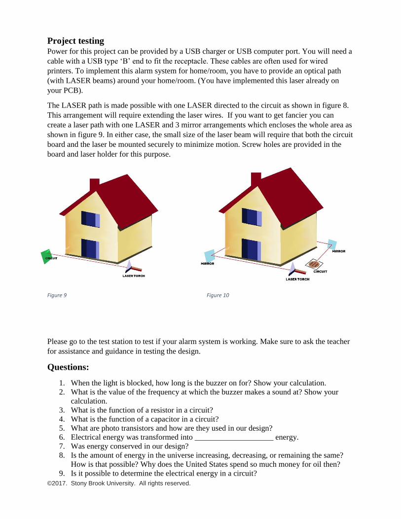
The LASER path is made possible with one LASER directed to the circuit as shown in figure 8.
This arrangement will require extending the laser wires. If you want to get fancier you can
create a laser path with one LASER and 3 mirror arrangements which encloses the whole area as
shown in figure 9. In either case, the small size of the laser beam will require that both the circuit
board and the laser be mounted securely to minimize motion. Screw holes are provided in the
board and laser holder for this purpose.
Figure 9 Figure 10
Please go to the test station to test if your alarm system is working. Make sure to ask the teacher
for assistance and guidance in testing the design.
Questions:
1. When the light is blocked, how long is the buzzer on for? Show your calculation.
2. What is the value of the frequency at which the buzzer makes a sound at? Show your
calculation.
3. What is the function of a resistor in a circuit?
4. What is the function of a capacitor in a circuit?
5. What are photo transistors and how are they used in our design?
6. Electrical energy was transformed into ____________________ energy.
7. Was energy conserved in our design?
8. Is the amount of energy in the universe increasing, decreasing, or remaining the same?
How is that possible? Why does the United States spend so much money for oil then?
9. Is it possible to determine the electrical energy in a circuit?
©2017. Stony Brook University. All rights reserved.
Think like an engineer - Questions & Discussion:
1. How can you change the time for which the buzzer is enabled? Can you suggest values of
R3 and C3 such that the buzzer sounds for 3 seconds?
2. Could this design be done without a timer chip? If yes, what effects will take place on the
design?
3. Besides cost, what are other potential issues with materials and design to be considered?
4. Do you think engineers have to make important tradeoffs between costs, environmental
considerations, and other issues?
5. Are there any other improvements to this design that you would employ?