building a battle station model
TRANSCRIPT

I. Introduction
The summer is usually a pretty difficult time forme to work in my workshop. Chores aboundaround the house and there is seemingly some-thing to do almost every day that precludes anyuseful time spent in the workshop. The summerof 2004 was no different. By the time late Julyrolled around, I was desperate. I had not madeanything for over a month. Something had to bedone. What to do? Then it hit me. I was lookingover the latest Model Expo catalogue and sawthey still offered kit models of small battle sta-tions. Not wanting to build a kit, I saw the poten-tial for a quick scratch built project. Over thenext two weeks I built a pretty little battle stationmodel that turned out to be quite a conversationpiece.
As fate would have it, that model was destroyed whenHurricane Katrina washed away the local museum. I havedecided to replace the battle station model, but it occurredto me that others might benefit from my experience havingbuilt it. So, I redrew the plans, making some improve-ments, and decided to set down a guide to building themodel. I am not an expert and I make no claim that mymethods are the only way to build the model. Someonebuilding from these plans should view my words as a col-
Building a Battle Station Model
By Russell Barnes
lection of helpful hints rather than a map to follow in orderto arrive at a desired result. I envision this project as anintroduction to scratch building. My hope is that the builderlearns a few scratch building techniques that will help, notonly on this model, but also in future projects whether theybe kits or scratch built. There is nothing difficult here, but itwill require the same level of patience and attention todetail to complete the model satisfactorily that is requiredof any well made model. If a beginner scratch builder cansuccessfully complete this model, then I think the effort todraw the plans and set down some ideas about how tobuild it are well worth it.
The tools you will use to build this model are, for the mostpart, in every ship modeler's tool chest. The only powertool I used in building this model was a 4" table saw that
A view of the author's small workshop
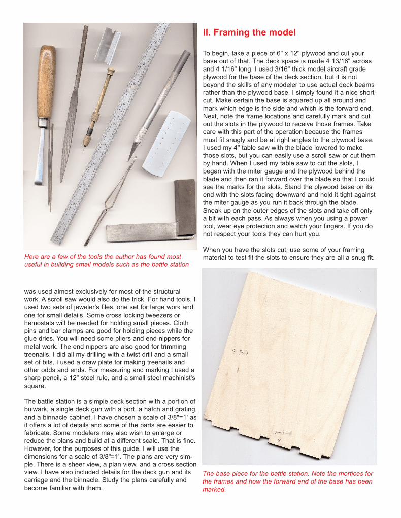
was used almost exclusively for most of the structuralwork. A scroll saw would also do the trick. For hand tools, Iused two sets of jeweler's files, one set for large work andone for small details. Some cross locking tweezers orhemostats will be needed for holding small pieces. Clothpins and bar clamps are good for holding pieces while theglue dries. You will need some pliers and end nippers formetal work. The end nippers are also good for trimmingtreenails. I did all my drilling with a twist drill and a smallset of bits. I used a draw plate for making treenails andother odds and ends. For measuring and marking I used asharp pencil, a 12" steel rule, and a small steel machinist'ssquare.
The battle station is a simple deck section with a portion ofbulwark, a single deck gun with a port, a hatch and grating,and a binnacle cabinet. I have chosen a scale of 3/8"=1' asit offers a lot of details and some of the parts are easier tofabricate. Some modelers may also wish to enlarge orreduce the plans and build at a different scale. That is fine.However, for the purposes of this guide, I will use thedimensions for a scale of 3/8"=1'. The plans are very sim-ple. There is a sheer view, a plan view, and a cross sectionview. I have also included details for the deck gun and itscarriage and the binnacle. Study the plans carefully andbecome familiar with them.
II. Framing the model
To begin, take a piece of 6" x 12" plywood and cut yourbase out of that. The deck space is made 4 13/16" acrossand 4 1/16" long. I used 3/16" thick model aircraft gradeplywood for the base of the deck section, but it is notbeyond the skills of any modeler to use actual deck beamsrather than the plywood base. I simply found it a nice short-cut. Make certain the base is squared up all around andmark which edge is the side and which is the forward end.Next, note the frame locations and carefully mark and cutout the slots in the plywood to receive those frames. Takecare with this part of the operation because the framesmust fit snugly and be at right angles to the plywood base.I used my 4" table saw with the blade lowered to makethose slots, but you can easily use a scroll saw or cut themby hand. When I used my table saw to cut the slots, Ibegan with the miter gauge and the plywood behind theblade and then ran it forward over the blade so that I couldsee the marks for the slots. Stand the plywood base on itsend with the slots facing downward and hold it tight againstthe miter gauge as you run it back through the blade.Sneak up on the outer edges of the slots and take off onlya bit with each pass. As always when you using a powertool, wear eye protection and watch your fingers. If you donot respect your tools they can hurt you.
When you have the slots cut, use some of your framingmaterial to test fit the slots to ensure they are all a snug fit.
The base piece for the battle station. Note the mortices forthe frames and how the forward end of the base has beenmarked.
Here are a few of the tools the author has found most useful in building small models such as the battle station

The frame should just slide in with a slight amount of fric-tion. If you need to take a bit more off, I would suggestusing a coarse file to touch up the saw cut. One key tomaking accurate cuts is to have a sharp pencil. The sharp-er the pencil lead, the crisper the lines, and the more accu-rate the cuts. Measure the deck beam locations from theplan view and mark these out on the plywood base. It isbest to have these marked out so that you can treenailyour deck if you wish when you plank the deck.
Once the plywood base is cut with the frame slots, usesome 3/16" square basswood to make up your frames. Youcould use solid 3/8" thick stock for this, but I had some3/16" sheet stock from which I ripped my framing material.Another good reason for using the smaller stock and gluingthem up in pairs is that if the slots you cut are a bit larger,the glue seam between the two frame halves will take upsome of the space. I cross cut the frame sections on mytable saw, using the miter gauge and rip fence to ensureconsistently correct length and squared ends. Once youhave the pieces cut for the frames, glue them up to create3/8" sided thickness (when viewed from the side) and 3/16"moulded thickness (when viewed from fore or aft) frames. It is a good idea to take each frame and lay it down on the
cross section drawing and compare its length to that in thein the drawing. If there is any discrepancy, remark yourframes for length and re-cut the offending pieces. If you donot, your rail will not sit properly. Of course, if you meas-ured and cut carefully the first time around, there should beno problem. Now, install the frames in the slots in the base,gluing each frame in and squaring it up with a machinist'ssquare. Do not get careless here because the frames mustall be at right angles to the plywood base and at the sameheight. If they are racked out of line, even in the slightest,the planking will not lie flat on the frames. If you need toadd shims, that is fine. They will not be seen in the finishedproduct. The most important thing is to get those frames allsitting perfectly square in their slots. I found that by settingthe outermost frames first and then working inward to thegun port was the best way to go. For the purposes of build-ing the model, I found that it was helpful during the framingand planking process to number the frames 1 through 5beginning from the far left, moving along the bulwark to theright. This is not necessary, but it helps to keep things asorganized as possible.
The next project is to install the gun port sill and lintel. Thesill marks the bottom edge of the port and the lintel marksthe upper edge. These are two pieces of basswood, 3/16"square. On the sheer plan measure up from the bottom ofthe base to the lower edge of the port. Mark that on thethird and fourth frames. That is the upper edge of the sill.Make sure when you install the sill that the upper edgemeets those marks. Measure carefully so you do not havethe sill sitting at an angle. I used a machinist's square laidon the end frame to make sure the marks for the sill andlintel were transferred onto both frames 3 and 4. Repeatthis operation with the lintel, the only difference being themark you make will represent the lower edge of the lintel. Itis a good idea to have a sample of the planking that will runjust above and below the gun port to act as a gauge tomake sure you have the sill and lintel properly placed. Youare looking for the correct height and to double check thatthey are level.
An outboard view of the bulwark framing
The bulwark frames for the battle station model. Thesehave been built up of two pieces of basswood

An inboard view of the bulwark framing. Note the simple use of lentil and sill to frame the gun port
An outboard view ofthe bulwark framing.Note how the framesfit into each mortice

III Bulwarks planking
With the framing completed, you can now begin work onthe bulwark planking. You can begin on the inside or out-side of the bulwarks; it matters not which. I began on theoutside. I like to mark out the run of the planks even thoughthey are straight and without any difference from end toend. From the cross section plan, measure for the height ofeach plank from the bottom of the base and transfer thesemarks to each end of the bulwark frames. Again, use asharp pencil and measure carefully. Strike a line betweenall the opposing points to get your planking reference lines.
I should say something about treenailing at this point. If youwish to treenail the planking, it might be better to do it asyou go, rather than fit all the planks and then treenail.Treenailing as you go makes it easier to line up the treenailpattern because you can see the frames as you nail theplanks. For each frame, the plank should receive onetreenail centered in the upper outer corner of one side ofthe frame; then another centered at the lower outer cornerof the other half of the frame. At the sides of the port, twotreenails go in arranged vertically, one right above theother. I think a number 75 drill bit will be about right for thisscale.
To make your treenailing material, a draw plate is neces-sary. Many modelers are a bit shy about using a drawplate. It is not that difficult. You can draw down any wood,but I find, as have many modelers before me, that bamboois a good choice because it is easily split down its grain,but is fairly sturdy across the grain. Bamboo is actually agrass, but it seems to do very well imitating woodentreenails. A couple of good sources for bamboo are theskewers that you can buy at the local grocers and a longfishing pole that can be had at the local bait shop. To use
your draw plate, take a piece of bamboo about 6-8" longand split it down the length repeatedly until you have astrip that is just a shade large than your finished size. Inever want to have to pull through more than 5-6 holes toget to my desired diameter. Sand one end to a point andthen test it in a hole that is several sizes larger than yourtarget diameter. You can hold your draw plate in a benchvise, if you have one, or you can do as I do and hold it inyour left hand and pull the bamboo down through the holeswith the thumb and forefinger of your right hand. I am righthanded so for those who are lefties, they may want toreverse that process. When pulling the bamboo throughthe draw plate, give it a good sharp pull, leading with theend that was sanded down. Pull the bamboo through thesame hole several times, altering the angle of the pull inseveral directions, and on each pull, changing the angleslightly. I also make a point of flipping the bamboo strip endfor end and leading with the other end for a while beforeflipping it back to the original end leading through the hole.Only when you have the bamboo pulling through a holewithout any material coming off should you move onto thenext hole. If for some reason, the bamboo binds up, wet itdown with water and pull it through a few times.
Before actually cutting any planks, consider the finish ofthe planking. I chose cherry for the wales and then paintedit black before installing the rest of the planking. This savedme from having to mask off the areas of the planking that Idid not want painted. My idea was to have the black walesand then a contrast of natural finished boxwood for the restof the upper planking. For the inner bulwarks planking, Ijust used a natural finish, but you could paint the inner bul-warks red or ochre if you chose. If you choose to keepyour planks with the natural finish, I would suggest using apencil to darken the edges of the planking on both theinner and outer bulwarks. The seams will show up betterand enhance the finished look of your work. Of course, ifyou paint, then there is no reason to darken the edges ofthe planks unless you really want the seams to show up.For this model, there is no absolute right or wrong finishedappearance, but you should consider the finish before youbegin to plank.
An outboard view of a larger battle station model. Note theplanking seams and the use of bamboo tree nails. Alsonote the painted wales.
The author's drawplate and a
piece of bamboo drawn down for
treenails

The first planks to install are the wales. The wales are thethick planks that run along the ship's hull just at or near itswidest girth. On the model we have two wales planks.These are thick planks and will require some clamping. Iused mini bar clamps, but you can use c clamps or evenclothe pins if they will fit. Rip your stock and cut the planksto length, leaving them just a shade long for final fitting.Clamp the plank in place, making sure it meets the marksyou made earlier and then mark the long end on the backof the plank. Remove the plank and then sand its end orcut it on the table saw to that line. Now glue it onto theframes, and clamp it. When the two wales planks are in,carefully fit the next plank up, called the black strake. Itgoes in just below the gun port. This plank needs specialattention because it must run just along the underside ofthe port and its upper edge must be flush with the upperedge of the sill. If you need to sand or rip a little more offthat plank's upper edge that's fine. It must fit correctlyunder the port.
The plank that runs along the upper edge of the port goesin next. Fit this plank and then glue it on as you did withthe planks below the port, but this time make sure theplank meets the lower edge of the lintel. Also, while youhave it clamped on temporarily, measure the distance fromits lower edge to the upper edge of the black strake ateach end of the bulwarks. This is an additional check tomake sure you have equal space for the three thinnerplanks that fit in the way of the port. Once you are satisfiedwith the fit and placement of the plank, glue it on andrecheck that distance to ensure it sits level and that youhave equal spacing for those three thinner planks. The thinner planks that run in the way of the port go innext. I fit these as full length planks and then removed thesections over the gun port. Clamp them onto the bulwarkso that they are all aligned properly. While they are
clamped on, mark their inside faces in the way of the gunport so that they form butt joints on frames 3 and 4 thatform the sides of the gun port. Make sure your pencil issharp and you are making accurate marks on the planksthrough the gun port from the inside of the bulwarks.Remove the planks and cut out those sections that coverthe gun port. After you cut out the parts of the planks thatcover the ports, fit each plank, keeping one end flush withthe edge of the port and measure it at the end of the bul-wark to get the length. When they are installed, you shouldhave a nice flush edge at both sides of the port. With the outer bulwarks planked, you can tackle the innerbulwarks. The methods are pretty much the same.Measure out from the cross section plan where the plank-ing seams will fall and transfer these measurements to theinner side framing. Pay attention to the upper and loweredges of the gun port as you did with the outer planking. Itis just as important that the inner planking line up with thegun port. If you wish to treenail, then do it as you go alongwith each plank. With the exception of the waterway, therest of the inner bulwark planking is 1/16" thick.
Since the waterway plank is actually part of the bulwarksplanking rather than the deck planking, it should go on first.It has a special profile that needs to be made first. Beginby ripping a piece for the waterway 3/16" "square. If youhave a table saw with a tilting arbor, then you can tilt theblade and remove the majority of the material from thewaterway that needs to come off to form the distinctivecove profile. If not, then you can mark the area to removedboth ends of the waterway, using a straight edge to con-nect the points. Do this for the upper edge of the waterwaywhere it will blend in with the rest of the bulwarks plankingand also down near the deck on its outer edge where it willblend in with the deck planking. This will give you two ref-erence lines showing where the material should beremoved. With the reference lines you can file or sand off
An outside view of the author's first battle station modelunder construction. Note the planking and the use oftreenails
Bar clamps and spring clamps can be used to get a tightglue joint when assembling bulwark planking

the unwanted material. Take care to do this carefully andgo slowly. When you have the material removed to thosereference lines, you should have a 1/16" thickness on theupper inner edge of the waterway where it meets theinner bulwark planking as well as the outer lower edgethat will flow into the deck planking. Once you have thewaterway's profile roughly shaped, you can use a curvedexacto blade to scrape in the cove profile. You could alsouse a piece of sandpaper wrapped around a small dowel.If you use sandpaper let me recommend somethingcoarse, say 80 grit or so.
There is one other point in the inner bulwarks plankingthat requires mentioning. There is a belaying pin rack thatfits into the upper edge of the third plank down from therailing. When installing this plank, take care to measureand cut out that portion of the plank where the pin rackwill fit. The pin rack needs to fit against the framing toanchor it properly, so the plank must be cut out to admitthe pin rack. To cut this area of the plank, I used my scrollsaw and then cleaned up the cut with some fine sandpa-per. If you plan to paint the inner bulwarks, now is thetime to do it. Once the deck planking is in, it will be moredifficult.
The last piece to go on the bulwarks is the cap rail. Thisis a piece of hardwood that sits flush with the inner andouter planking and flush with the ends of the bulwarks.On my first battle station model, I made the cap rail fromcherry and left it natural, but now I think it might look
better painted black. If so, you might consider pre-painting iton the top and the edges. Then you can install it and treenail it to the frames with little problem. The only thing toremember is that if you paint it first, then install and treenailit, the paint on the top of the rail will have to be touched upafter the treenails are trimmed off. To fasten the cap rail, usea number 61 drill or something close and put one treenail inper frame.
A view of the inner bulwark planking of
another battle stationmodel. Note the
staggered joints in theplanking and how theplanks line up with the
top and bottom of the gun port.
A close up view of the waterway for the battle station model.This was made from mahogony. A chisel was used to formthe cove detail.

IV. Deck planking and the hatch
The deck planking is next. The deck was planked withscale 1/16" thick basswood strips 3/16" wide. To indicatecaulked seams, I took a board of basswood 3/16" thick andpainted one side of it black. I then ripped off the 1/16" thickdeck planks along its edge so that when I laid them blackedge to plain edge, I got a nice uniform caulked seam.Before laying the deck planks, it is well to mark out theposition of the hatch coaming first to make sure you arekeeping everything nice and square. In fact, you mightconsider making up a plywood template to the exact samesize as the outer edges of your hatch coaming. You canuse this template as a gauge for when you lay the plankright around the hatch coaming. I found this template mosthelpful in keeping the edges of the plank all evened out sothat when the actual hatchway was put in place, all theseams were nice and tight. If you want to indicate plankingbutts in the deck, then now is the time to map them out.Keep in mind there should be no planking butts in thestrakes (lines of plank) that run into the hatch coaming.There should be three strakes of plank between plankingbutts that fall on the same beam. Armed with this informa-tion, you can lay out your planking butts and then beginlaying plank.
As you lay the planks, it is a good idea to check theremaining area to be planked at each end of the deck tomake sure your planks are going on square. Even with fac-tory milled stock it is not impossible for planks to creepover more at one end. As with the hull planks, treenail asyou go rather than after all the planks are in. For deckplanking, each plank gets one treenail centered in the deckbeam over which it passes and two treenails side by sideat each plank butt. Where the deck plank butt into thehatch coaming, they are treated as planking butts.
With the deck planking completed, it is a good time toinstall the hatch coaming. The hatch coamings are joinedtogether at each corner with a half-lapped joint. I know thatmany models call for a miter joint, but that is just not cor-rect. I made my hatch coaming out of walnut, but you canuse whatever hardwood suits you. For the hatch coaming,you will need four lengths of material 5/16" wide and 3/16"thick. The half- lapped joints will occur in the width of thecoamings and not the thickness. I used my table saw forthis operation, lowering the blade and running the piecesover the blade to remove the unwanted material. You coulduse the scroll saw for this work, but it will have to be donefree hand and it is difficult to get perfectly matched jointsthat way. I carefully cut each length of coaming so it fitsnugly into the space left open on the plywood base duringdeck planking. If you used your template to help size thatopening and keep it squared up, you will thank yourselfnow as you fit the coaming. When you are satisfied with the
Ripping a deck plank off the side of a sheet of basswood.Note that one side of the basswood sheet is painted black
Overhead view of another battle station model's deckplanking. Note the hatch coaming and grating
The plank after it is cut off the basswood sheet

fit of your coaming within the deck opening and the joints ateach corner, you can glue the coaming together setting itlightly in the deck opening to keep it square as the gluedries. Once it has dried hard, I would suggest doweling ittogether, running the dowels right down through each joint.Also, glue in some strips on the inside of the coaming. Ripthese strips to ¼" wide and 1/16" thick. Glue them in sothat they sit flush with the bottom of the coaming and 1/16"shy of the top. This will do two things. First, if will furtherstrengthen the structure and second it will form a lip uponwhich your grating will sit. As a final touch for my hatchcoaming, I ran it through the table saw with the blade tiltedslightly to take off the upper outer corners of the coamingstructure. This is not an absolute necessity, but it was com-mon practice to chamfer the upper edges of the coaming. Ileft about 3/32" flat along the top edge of my coaming.
V. Grating
With the hatch coaming in place, I made a boxwood grating for it, using a technique I read about in NRG'sShipmodelers Shopnotes. I have used this method to makeseveral gratings and it works very well. Although I supposeyou can use many different hardwoods to make gratings, Ihave only used boxwood and that is the wood I willdescribe using. To use this method, you will need a strip of1/16" thick boxwood and several 1/16" square sticks of box-wood. You will also need a 4" table saw with a zero clear-ance insert so that small bits cannot fall through the table. The boxwood strip needs to be sized so that its length isthe same as the width of the opening in the hatch intowhich the grating will fit. Keep the strip's width at leasttwice the width of the opening. Once it is sized, glue asquare stick onto the strip with the grain of the square stickrunning at right angles to the strip. Glue the first stick on,and then use a spare stick of the same size to act as a
A hatch coaming made for the Battlestation model. Notethe ledges on the inside to hold the grating
A view of the half lapped joints on the hatch coaming
spacer while gluing on the second stick, and so forth. Thisensures that each stick is glued on with absolutely equalspacing. Once the assembly is dried hard, set the rip fenceon your table saw to rip off 1/16" thick strips of material.Lower the blade so that it is slightly higher than the pieceyou are cutting and then rip sections off the assembly, run-ning the assembly through so that the base strip is perpen-dicular to the blade. You are producing "racks" of materialthat, when turned on their sides and joined, will form thegrating. The "rack" will have a solid strip with little"chunks", actually the ends of the sticks, protruding from it.Rip as many "racks" off this assembly as possible.
To assemble the racks into a grating, make a right anglejig. Square up a small piece of scrap plywood a bit largerthan your grating. Glue on a hardwood strip along oneedge so that it sits on top of the plywood. Glue anotherstrip onto the plywood at right angles to the first strip. Nowyou can assemble your grating in the right angle thus cre-ated. Check your jig with a machinist's square to makesure it is really a right angle. Now, place glue on the tips ofthe "chunks" of a boxwood rack and glue another rack to itwith the solid side to the "chunk" side. Place it in the jigand make sure it is aligned. Repeat the process until youenough racks glued together to make up the grating. Whenit is all dried, place it in the hatch opening and check thegrating's squareness and fit. You may need to add a thinstrip of boxwood to one side to close off the grating. Youmay also need to trim one or more of the grating's edgesslightly to get a nice fit in the hatch opening.
Here are the steps involved in making a grating. Note how the individual components are used to form the entire grating

VI. Building the Gun Carriage
A battle station needs a gun, and it is next on the list.There are a few options at this point. You can do as I didand turn your gun barrel, you can cast it if you have theknack for that, or you can buy one of the appropriate sizefrom a model supply house. I turned a gun-barrel out ofbirch and painted it black. If you wish to turn the barrel,you can use my drawing for a template.
The carriage I designed is built up using a drawing I foundin Harold Hahn's Colonial Schooners book. I scanned thedrawing, enlarged it to 1/32 scale, and then made a fewsmall alterations to suit the model. If you wish to make thecarriage in the plans, make a poster board template foruse in marking out and checking the carriage bracketdimensions. To make the brackets, select a piece of woodthat is about twice as thick as both brackets put together.The piece should also be a bit longer than the brackets soyou will have a handle to hold on to during the shapingprocess. Shape the bracket's profile out of that thickerpiece, not forgetting to drill holes in the bracket for the eye-bolts and bed stool support. When the bracket is shapedand all the holes are drilled, set the rip fence on your tablesaw to slice the piece into two matching brackets. Theresult should be two matching brackets, one for each sideof the carriage with all the holes drilled so they match aswell.
To assemble the carriage, it is a good idea to create a jigaround which the brackets and axel trees can be assem-bled. I used a chunk of wood cut to match the insidedimensions of the carriage and then glued it to a smallbaseboard. Then the brackets and axel trees are assem-bled around it. It works rather well, provided the jig is cutaccurately. The rear end of the jig should be as wide asthe forward end of the rear axel tree, while the forward endof the jig should be as wide as the rear edge of the tran-som. Remember, these measurements are taken on theinside of the brackets. With the brackets, axel trees, andtransom assembled, all that remains to add to the carriageis the bed stool, bolster, and quoin. The bed stool's rear
section sits on the bolster that in turn sits on the rear axeltree. The bed stool has a half round cut out near its forwardend that sits on a support pin that runs right through bothbrackets.
Do not forget to add the eyeboltsand breeching rings to the sidesof the carriages as noted in theplans. These are absolutely necessary for rigging the gun. The breeching rings are madewith the same method as the eyebolts that I discuss below. You will use a larger diameter pin to form the eye and the eyewill be cut off the stem of the eyebolt and then mounted onanother eyebolt prior to installation on the carriage.
The carriage trucks can be madefrom a length of dowel that issized in the draw plate. Once youget the wood sized in the drawplate, mark and drill the holes for the axels. To make surethese holes are dead centered in the trucks, make a markon the trucks with a sharp pencil and then use the point ofa number 11 hobby blade to make a small dent for the drillbit to bite into when you drill the holes. If you have a drillpress with a vise to hold the work, you can set up thedowel in the vise and drill right down into the end grain ofthe dowel to create the holes. I have no drill press so Iused a pin chuck and eyeballed the hole from all angles asI drilled it. I drilled just deep enough for the first two trucks,then sliced them off on my table saw and then repeated theprocess for the last two trucks. The results were fairly goodto my eye. By the by, to slice the trucks off the dowel, crosscut the dowel, holding the dowel against the miter gauge.To keep the truck from flying off the dowel when the sawblade parts it off, hold a piece of scrap wood with somedouble faced tape on it against the end of the dowel to holdthe truck after the saw blade goes through the dowel.
Author's custom made gun barrel for the battle station's gun A basswood block jig for assembling a gun carriage

A nearly completed gun carriage The completed gun carriage and gun

VII. Blocks, rope making, and metal work
The blocks are built up out of boxwood and are 7 scaleinches long. For the gun tackles you will need two doublesheaved blocks and two single sheaved blocks. To buildthe blocks, use two side pieces with a spacer sandwichedbetween the sides at the upper and lower ends. The sidepieces, called cheeks, are 7/32" long, about 7/64" wide,and 1/32" thick. The spacers at the upper and lower endsare 3/64" square. To make the double sheaved blocks, adda 1/32" strip just like the cheek pieces in the middle to formtwo sheave holes rather than one. Clamp these blanks inbar clamps to get a tight glue joint. After they are dry, thesheave pin hole is drilled right through the shell of the blockfrom side to side. A brass sheave is inserted into the shelland a brass pin is glued into the hole so that the sheaveturns on it. The sheave can be sawn off the end of a brasstube or it can be bought ready made. I found that 3/32"diameter sheaves worked for these blocks. Such sheavesare readily available from model supply houses. Once theblock has its sheave, it can be shaped using files andsandpaper. A stropping groove is filed into its sides andboth upper and lower ends. Of course, if you wish to usestore bought blocks, they can be made to look very realis-tic. But, I think the effort to scratch build just what you wantrather than buying a block and reshaping it to make do ismuch more satisfying.
The rigging for the gun was made up out of linen thread. Itwisted up my rope to use for the straps, breeching, andthe gun tackles, but you can just as easily use store bought
rigging thread. I made up a system for producing lengths ofrope. It is rather unconventional, but it works fairly well. Idrill a small piece of dowel and screw a small brass hookin its end. I chuck this dowel up in a cordless drill andattach three threads to the hook. The other ends of thethreads are tied to a brass pin set in a hole at the far endof my workbench. I hold the drill so that the threads aretight, and then I pull the trigger, twisting the threads untilthey are tightly wound around each other. At this point theirnatural tendency is to release the built up tension byunwinding. I remove the thread from the hook in the drill,
How to manufacture built uprigging blocks. Note theglued up blank and the useof bar clamps
The author's home made jig used for cutting off rings ofbrass tubing for rigging block sheaves on a table saw
An overhead view of the author's first battle stationmodel. Note the built up rigging blocks used for the gun tackles
The finished blocks aftershaping. Note the groove forthe rope strop

holding them taut so they will not unwind. Still holdingthem taut, I double the threads back on themselves, fas-tening both ends around the brass pin on the far end ofthe workbench where the other ends of the thread are tied.Now, holding the threads taut, I move my thumb and fore-finger back along the threads about 1" or so, allowing thereleased section to unwind. Because the twisted threadshave been doubled back on each other, they will lay upinto rope as I allow them to untwist in small lengths. I con-tinue moving back along the twisted up threads, little by lit-tle, allowing small sections to lay up into rope. As eachsection lays up, I give another extra twist to tighten the layof the rope. Finally, when the entire length is laid up rope, Iadd a spot of cyano glue to the end of the rope and cut offthe loose ends. The finished size for the tackle is .024"while the breeching is about .040". Both lines are dyedwith Minwax Special Walnut stain. The block strops aremade up out of linen and finished at.024". They are dyedwith Minwax Jacobean stain.
The breeching needs a cut splice in its middle to fit aroundthe pommel on the rear of the gun barrel. To make a cutsplice, take about a ½" length of the same rope as thebreeching and fray the ends a bit. This short length of ropeshould about the length of the loop you intended to make,
maybe a tad longer. Now cyano glue this length onto thebreeching rope and wrap those frayed ends of the splicearound the breeching so that they blend in a bit. This cre-ates a small loop. Now cover the ends of the rope thatwere glued with seizings of .010" diameter thread dyed thesame color. The result is a fairly realistic looking, but fake,cut splice. Set the breeching aside for the moment. The iron work is all blackened brass and blackenedannealed steel wire. Blackened steel wire can be pur-chased from model supply houses in various gauges. Itcomes pre-blackened and is therefore a very attractivealternative to using brass wire that would have to be chem-ically treated with a blackening agent. Before any blocks
This illustrates the set up for spinning several strands of thread to make model rope
The hook mounted in the drill withthreads attached
The threads attached at the oppositeend to the brass pin
The twisted up threads folded backonto themselves and allowed totwist up into rope
A finished cut splice ready for mounting on the gun barrel
A method for making afaked cut splice
A piece of home
made rope

are stropped, the hooks by which they attach to the eye-bolts in the sides and the gun carriages must be made.For the hooks, I used black annealed steel wire. About 28gauge will do. Wrap the wire around a number 67 drill bitshank to form a loop through which the strop will pass.Now, on the other end, use your pliers to form the hookand use your end nippers to cut the tail of the hook off toa correct length. The looped end of the hook should besoldered at this point. This can be done with soft solder-ing, using a soldering iron, or by hard soldering using asmall torch. Having learned hard soldering, I will suggestthat method, but soft solder will do for a joint that will notencounter any stress.
For hard soldering, you need a small torch and some pre-fluxed soldering paste. I hold small parts in a pair of crosslocking tweezers or hemostats while I am soldering. Makesure the metal is clean and make sure the two points tobe connected are touching. I like to file the pieces downand then over bend the pieces so that I can spring them
together to make sure the twopoints are actually touching.Apply a tiny fleck of paste andthen apply the torch. Lookclosely and when you see thesolder flash, immediatelyremove the flame and the jointis made. It takes some prac-tice, but if you keep the piecesclean and touching, the restshould follow. To make eyebolts, I use asmall jig shown to me by fellowmodeler Bob Craig. Take acommon piece of woodendowel about 5-6" long and saw
a slot into one end of the dowel, extending about ¼" downinto the dowel. Now, drill a hole at right angles to the slotand through the slot. Insert a piece of brass wire into thathole. The wire should be the same diameter as the eye of
the eyebolt you are making. Now, take another piece ofwire and thread it into the slot, looping it around the otherwire. Bring the free ends of this wire out of the slot andtwist them. I use pliers to hold the wire in one hand whiletwisting the dowel in the other. Eventually, the wire willbreak, but that is good. Now, carefully remove the wire thatwas in the hole and a neatly made eyebolt will fall out ofthe slot. This eyebolt has a threaded shank and with a bitof trimming on the shank is ready to install in a predrilledhole wherever you need it. I have made several of thesejigs, each for different sized eyebolts. No soldering is nec-essary in these eyebolts. If you use blackened annealedsteel wire, then no other treatment is necessary. If you usebrass, then they will need to be chemically blackenedbefore installation.
Using a modified third hand device to make a cut splice
An easy and fast way to make realistic looking eyebolts
Rigging blocks withscratch built hooks
VIII. Rigging the gun
The double sheaved blocks and the single sheaved blockswill each have slightly different stropping methods. To stropthe double sheaved blocks, cyano glue one end of the stroponto the arse end of the block. Thread a hook onto the stropand then bring the strop up and over the head and down theother side of the block. Cyano glue the free end of the stroponto the arse end of the block, blending it in with the otherend that is already glued on. In doing this trap the hook upagainst the head of the block. Make sure to be sparing withthe glue to make a neat job of it. Now you have stroppedblock with a hook on it ready for rigging. Although manymodelers think you have to form a becket or loop in thestrop to hold the hook, it is actually not always true for thelate 18th century. Back then, they quite often just ran thehook through the strop without any becket.
One thing to remember in rigging the gun tackles is the runof the tackle line. The tackle rope will be seized to the arseend of the single block, then run down through the innersheave of the double block, then back up through the singlesheave of the single block, and then back down through theoutside sheave of the double block. To seize the tackle linein the strop of the single sheaved block is simple. Simplyseize the tackle line as you normally would around the stropline before you install it on the block. When the seizing hasdried, cyano glue the strop with the seized tackle line onto

the arse end of the block and run the strop up around theblock on either side. Slide the hook for the single blockonto one leg of the strop and then cyano glue that leg ofthe strop up over the head of the block, trapping the hookin place. Then finish the strop by bringing the remaining legof the strop over the head of the block and cyano glue itdown, blending it in with the rest of the strop. The key is tomake that joint neat. I use a single edged razor to neatlytrim the excess on each end of the strop that is glued onthe head of the block.
To rig your gun, first drill your holes for the eyebolts in thebulwarks. The breeching eyebolts are set down low nearthe waterway and just on either side of the port. The gun
tackle eyebolts are set about 1 1/8" out from the port andabout 1/3 the way up from the deck. The key to rigging thegun is to pre-rig the tackles. It is easier to pre-rig the ropesand then attach them, blocks and all, after the gun is setinto position. I fastened my gun carriage to the deck usingbamboo locator pins set into the bottoms of the trucks. Tojust glue them would have probably worked, but I wantedto make sure the gun would not come loose. With the gun
fastened in place, pre-rig the breeching rope by making itseyebolts on either side and then seizing the breeching tothe eyebolts. It is important to check the length of thebreeching as you attach the eyebolts. Set the cut spliceover the end of the barrel and glue the eyebolts into theholes you have drilled in the bulwarks. Make sure to let thebreeching lay down loosely on either side of the carriage ifthe gun is run out. Only if the gun is run in for loadingwould the breeching be pulled taut. Go ahead and glue inthe gun tackle eyebolts on the bulwarks. Connect the pre-rigged blocks with their hooks to the gun carriage and theeyebolts in the bulwarks. The free ends of the gun tackle
should be glued to the deck using diluted white glue. Theywill be covered with rope coils. If you wish you can add some extra details for the gun suchas a flexible rammer and sponge, and perhaps a worm forremoving charges from the gun. The flexible rammer andsponge is made with a piece of rope for the flexible handle.The rammer can be made from a small piece of dowel
Side view of a stropped block readyfor rigging to the gun tackle
Frontal view of a stropped block readyfor rigging. Note the invisible splice at
the arse end of the block
A nearly side view of the stroppedblock. Note the strop running right
through the end of the hook
The rigging of the breeching and the gun tackles. Note the rope coils on the deck
Here is a single block complete with gun tackle line seizedonto the block. Note the seizing and how it blends in withthe strop. Frontal view of the block. (left) Note how thetwo ends of the seizing blend in together at the top

painted black with a hole drilled in one end to glue in therope. The sponge can be made by wrapping thin strips ofmasking tape around the end of the rope. Paint the tapestrips black. You can also use some cotton, but the fluffierthe material you choose, the more difficult it will be to getthe correct scale effect. The rammer and sponge shouldnot be much more than 1/16" in diameter. On my model,the rope I used for the flexible handle was some of thesame rope I used for the gun's breeching, but I think Iwould use something a bit smaller now.
For the worm, you need a thin dowel of smaller diameterthan the gun's bore and a metal "curly q" shaped imple-ment on it end. I made this metal part from stranded cop-per wire pulled out of some old electrical conduit. Thestranded copper wire is flexible enough to be twisted invery small coils and it looks about right for the scale. Formthe worm by wrapping the wire concentrically around thedowel several times to a length of about ¼" or so. Leavethe very end of the piece sticking out from the coil on bothends and glue the back end of the coil into a hole drilledinto the end of the dowel. The dowel for the worm issomewhat longer than the bore of the gun. I laid theseimplements out on the deck near the gun and white gluedthem to the deck.
The flexible rammer andworm for the gun. Notethe delicate metal onthe end of the worm
IX. Pin rail and belaying pins
With the gun installed and rigged, you can make the pinrail. Cut the rail to length from a strip of 1/8" thick, 9/32"wide cherry and then drill holes for six belaying pins. Usethe plan view of the pin rack as a template to locate thecenters for the belaying pin holes. Center punch at themarks for the holes to give your drill bit something to biteinto. I made my holes with a number 61 drill bit and thenenlarged the hole slightly as needed for the shanks of thepins. Attach the pin rail to the bulwarks using locating pins.Drill matching holes in the edge of the pin rail and the bul-
wark frames. Glue in bamboo locating pins to the pin railedge and glue the entire assembly into the bulwark frame.
You might think that a toothpick or other small store boughtdowel would be a good place to start, but I would cautionagainst either alternative. The store bought dowel will havetoo much cross-grained material in it and it might break orchip out at any point in the process. The toothpick is, to mymind, too much of an unknown. Of what wood is it made?How was it manufactured? If you cannot answer eitherquestion, it is much better to make the belaying pins out ofsome wood that is known to have good working qualities. Ahardwood is preferable, such as cherry, apple, or boxwood.I have made many belaying pins from 1/96 scale up through1/16 scale using cherry and it is a good wood to use, butmake sure to use clear stock. If it has a knot or a check,you could have a problem. So long as the stock is nice andclear, it will do just fine.
To make a belaying pin by hand, rip a piece of square stocka bit larger than the final diameter of the pin's head. It helpsto have a stick to work on that has about twice as muchmaterial as you will need in your finished pin. The length ofstock is about 6-8". On the end of the stick, mark out thelength of the shaft on the end of the stick and then in fromthat, mark off the head. As with every part of the measuringand marking process, make sure your pencil is sharp.Double check your measurements as well. I always keepthe shaft of the pin on the outermost end of the stick foreasier shaping. If you did it the other way, the pin shaftwould be so fragile that it might break before you were fin-ished shaping the pin's head.
The key to this technique is to be able to turn the stick slow-ly in your fingers as you remove material with the file. If youare right handed like me, hold the stick in your left hand andthe file in your right and begin turning the stick slowly withyour thumb, rolling it down your forefinger as you removethe material. Keep the ara you are working on close to yourfinger and thumb and balance the length of the stick against
This is how you can make small belaying pins with a jeweler's file. The same method can be used for makinglarge scale belaying pins.
BelayingPin

the four fingers of your left hand. As you turn the stick, youcome to a point where you can not turn it any further. Notewhere you are in the turning process and reposition thestick to continue. An alternative is to simply reverse theturning motion, but this could result in a lopsided piece.Use a 7" flat file to knock off the corners of the stick whereyou will shape the pin and then round it over. Continueshaping the shaft of the pin, turning it in your fingers asyou remove material. That 7" file will remove a lot of mate-rial in a short time.
When you have gotten the shaft rounded off, switch to the4" square file and use its corner edge to cut into the wood,marking the intersection of the shaft and the lower edge ofthe pin's head. Now, switch to a 4" flat file and begin finetuning the diameter. If you are not sure how far you haveto go, size the shaft in your draw plate. With care, you canremove the last bit of material using the draw plate. Onething to keep in mind when turning the shaft in your fingersis to make sure you keep an eye on your mark for wherethe shaft meets the bottom edge of the pin head. Thismark may be scratched off as you turn the shaft, but markit again with a sharp pencil to keep you on track. Whenyou have the shaft down to its final diameter, switch backto the 4" square cutting file and tune up the intersectionbetween the shaft and head. The pin must sit down proper-ly in its hole in the rack so make sure the intersection ofthe shaft and head is nice and square to allow it to do so.
With the pin's shaft sized, you can begin to turn the head.This can be a bit tricky, but with practice you can make anice looking pin. One important tip is to watch the length ofthe head in relation to the shaft. If the shaft is a bit long,that is okay because its bottom end can be trimmed offlater. However, the head's length needs to be monitoredcarefully to ensure it is not out of proportion with the rest ofthe pin. To shape the head, first take the diameter downwith your 7" flat file. The diameter of the pin head is slightlymore than the shaft. Get it down near the desired diameter,and then switch to the 4" flat file to get a better finish. Hereis a good point to mark the top end of the pin. Measurethis carefully and check it by holding the stick against yoursteel rule to see that you have the correct length and pro-portions. Now, take a 4" half round file and begin shaping
the bottom part of the head. The head of the pin has aslight concave bit in the profile just above its lower edge.Work this profile in with the half round file, working slowlyas you turn the piece in your fingers. The smallest diame-ter in the concave area will be worked down to a dimen-sion just shy of the shaft's diameter. Do not remove thevery bottom bit of the head. The pin head diameter shouldcontract as it goes down through that concave area andthen widen back out to just a shade more than the shaftdiameter right at the very bottom of the head. To finishshaping the head, use your 4" files to round over the headof the pin so that it begins to approach a point at the markfor the top end of the pin's head. The piece is very fragilenow because there is not much material left where the pinmeets the stick. You are nearly ready to part the pin off thestick. As you round over the top of the head, you will cometo a point, where the pin will have to be removed. Use arazor saw to part it from the stick and then hold it in yourfingers to finish rounding over the top of the pin's head. Bevery careful to keep hold of the pin as you part it off thestick. If you apply too much pressure on the saw, then thepin will probably end up in another universe. This, in turnwill lead to some very foul language. Once the pins are fin-ished, they can be stained a darker color if you wish.
These are some large scale pins made by the author foranother project
A view of another large binnacle cabinet by the authorshowing the compass installed
X. Building a binnacle cabinet
Next on the list is a binnacle cabinet. This is almost a proj-ect in itself, but it will be fun to create something so life-like for your battle station. I patterned my cabinet after theone described by Charles G. Davis in his book The Built-Up Ship Model. I made my cabinet out of cherry, but themain thing to remember is to use a good hardwood. Thebinnacle is a piece of furniture and I think it needs to bewell finished.

Begin by making up the side pieces. The sides are straightand 1/16" thick. There is a cut out in the bottom of the sidethat can be scroll sawn or filed out. Mark out where theshelves fall on each piece. There are two shelves for whichrabbets must be cut. It is best to mark them together ratherthan to mark them separately. You need those shelves tobe level and if you mark them separately, the risk increasesthat the marks are not really at the exact same level oneach side piece. I held each piece down side by side andused my machinist's square to mark the lines across bothpieces at the same time. I used my table saw to make therabbets for the shelves. I lowered the blade to about 1/32"high off the table and then ran both side pieces through inthe miter gauge with the rip fence set so that each rabbetwas in the same place on each piece. This same methodcan be used for making any rabbet where you need apiece to set into another for structure's sake. By using therabbeted joints, the piece will be a bit stronger than if youonly glued it together.
The shelves are more complex than you might imagine.The upper shelf needs two slots cut into its upper face to fitthe two vertical panels that separate the lantern compart-ments from the center compass compartment. The uppershelf should have a 1/32" rebate cut into its back edge toallow the back panel to fit between the two side pieces andcover the edge grain of the upper shelf. But, the shelfshould also have a 1/32" square chunk left at either end tofill the slot for the shelf in the side pieces. The front edge ofthe upper shelf should be flush with the front edge of theside pieces. The front panels for the lantern compartmentswill sit on the upper shelf and their inner ends will cover theedge grain of those two vertical panels that fit into theupper shelf.
The bottom shelf is an interesting problem. We want to hideits edge grain on both front and back, but we also need tomake sure that we fill in those mounting slots in both sidepieces. The answer is to cut a 1/32" rebate along both frontand back edges of the bottom shelf, yet leave a 1/32"square chunk at either end of the bottom shelf on both thefront and back edges. This will allow the front drawer panelto cover the edge grain of the bottom shelf and for the backpanel to cover the edge grain of the bottom shelf as well,and yet leave the slots filled in.
Once the side pieces and shelves have been cut and themounting slots created, it will be necessary to dry fit every-thing to make sure that it all fits together. The vertical pan-els that fit into the slots in the upper shelf must come up tothe bottom edge of the cabinet top. If they are too tall, thetop will not fit down onto the side pieces like it should. Onceyou have done a few dry fits and you are absolutely certaineverything fits, you can assemble the cabinet. Fit the bottom shelf first, gluing it into one of the side pieces. Use
The large scale binnacle cabinetshowing side doorsand handles
These are all the parts of the cabinet's carcass
The upper shelf. Note the slots for the vertical panelsand the cut out on the back side of the shelf
The lower shelf. Note the cut outs on both front andback sides of the shelf

a machinist's square to keep it at right angles to the side ofthe cabinet. Before fitting the upper shelf, fit the verticalpanels first. Glue them in and use you square to keep themexactly perpendicular to the shelf. Once the upper shelf isready, glue it into the side piece that has the bottom shelfattached. When it has dried, you can attach the other sidepiece. While the glue dries, use your square to keep every-thing nice and square. I cannot over-emphasize the needto use that machinist's square on a task such as this. It willsave you many headaches later on.
When the cabinet carcass is dried, you can fit the backpanel. The back panel is a 1/32" thick and cut to fit justunder the top, flush with the side pieces, and just level withthe bottom edge of the bottom shelf. If your cabinet waskept square as it dried, then the back panel should presentno problems. I found it very helpful to install some smallback pieces just inside the back panel on the side pieces.These backing pieces will give the back something to glueonto and just give it some extra positive support when it isinstalled.
The front drawer panel can be fitted now. Its upper edge isthe upper edge of the upper shelf while its lower edge isthe lower edge of the bottom shelf. Its sides are flush withthe inner edge of the side pieces. The grain for the drawerpanel should run horizontally. The two front panels for thelantern compartments can go in now as well. They sit onthe upper shelf and their upper edge fits right under thecabinet top. Their outer sides are flush with the inner edgeof the side pieces while their inner sides are flush with thevertical panels and cover the edge grain of those panels.Their grain should run vertically. As with the back panel,installing some backing pieces for the front drawer paneland the lantern compartment panels will help keep every-thing rigid.
Every binnacle needs a compass. To make a compass forthis cabinet, I just used a small disc cut off the end of adowel about 1/8" in diameter. I painted it brass and glued itonto the shelf in the middle compartment. If you can find acompass face in a book, scan it and reduce it until it fitsthe compass you have made. Just glue it right onto the topedge of the compass.
The binnacle cabinet carcass being rough fitted.
It looks like the uppershelf still needs
some work
Here is the cabinet fittedwith backing pieces. Note
the pieces for the backpanel, the front drawerpanel and the lantern compartment panels
The binnacle cabinet havingits back rough fitted
Battlestation binnacle drawer panel in place

Once the compass is installed, the top can be glued on.The top of the cabinet should have a slight bevel set into itsedges all around. I used a jeweler's file for this, but if youhave a better method, use what you know. Make sure whenthe top is glued on that it overhangs the structure on allsides equally. I fit two small locator dowels into the top ofeach side piece and then drilled matched holes into thebottom of the top piece. This way I knew when I sat thetop down onto the cabinet sides it was in the correct posi-tion. In fact, the system works so well, I did not even per-manently glue the top on my cabinet.
Once the top is on, all that remains is to fit the faux draw-ers on the front, the side doors, and the trim. The frontdrawers should have their edges slightly beveled. Takecare they are centered on the panel so that they look likethey belong. Before fitting the drawers, make up two cleatsfor handles and glue them on. Make sure these cleats aresmall and unobtrusive. They are there to suggest door han-dles. If they are too large, then scale effect is ruined. Weuse wooden cleats here because any iron on the binnaclecabinet would throw off the compass. The two small accessdoors on either end of the cabinet also need their edges
beveled slightly. Install small drawer handle cleats onthem as well before gluing them on. Take care to positionthe side doors so they could give access to the lanterncompartments.
The front trim piece below the compass compartment isactually made from three pieces. The corners are miteredas the trim wraps around the sides of the cabinet. Notethat the trim has its outer face rounded over on both theupper and lower edges. While it is no doubt possible toassemble these trim pieces off the binnacle and theninstall it as one piece, I favor installing the front piece andthen the two side pieces separately. It will be easier to cutthe miters and get a nice tight fit at the corners byinstalling the trim as three pieces instead of one. Thecurved bottom trim pieces can be scroll san, but I wouldrecommend that they be created on the end of a strip andthen the finished piece sawn off that strip. This will keepyour fingers from getting too close to the scroll saw blade.
The author's compass. Its rather crude, but then it does getmuch attention. Here is a great face for a compass if you
choose to make one this small .
The top being aligned for final fitting on the side pieces. Note the locator dowels and the corresponding holes in the cabinet top
A front view of the completed binnacle
cabinet. Note the fronttrim and the drawerswith very small wood
handles
A side view of the com-pleted binnacle cabinet.
Note the side accessdoors for the lantern
compartments

To mount the binnacle, make two small cleats, about aslong as the cabinet sides are wide. These should be fromabout 1/16" square stock. Glue these cleats on to theinside of the legs at the bottom and then glue the binnacleand the cleats to the deck, centered abaft the hatchway.For my tastes, I would also add bamboo locator pinsmounted in the bottom of those cleats and then drill corre-sponding holes in the deck to receive the pins. This willmore permanently affix the cabinet to the deck. I finishedmy cabinet with cherry stain and some clear sealer, but it isup to you how to finish yours.
XI. Finishing touches
If you like you could add a couple of figures, either madeup from clay or carved from boxwood or apple wood. Bothwoods make excellent material for carving. You can alsofind some suitable figures ready made, although they mightcost a bit. My thinking is that if figures are added, there
should be at least two figures. Adding one figure reallydoes not seem to make much of a difference, while addingtwo or more might really enhance the realism of themodel.
Well, that's about it, I think. This was a very nifty little proj-ect that took about two weeks and 34 working hours tocomplete. I learned a few new tricks with this little battlestation and it is a project that I would not mind repeating. Iwould recommend this type of model for anyone who islooking to test their scratch building skills before going onto a larger scratch built project. This model will not teachnearly everything you need to know about scratch building,but you can get your feet wet and learn a few valuabletricks along the way. You will have a nice looking model toshow for your efforts and you will probably look at scratchbuilding as a little less daunting for having built such asmall model. Of course, the most important thing toremember is to have fun.