building a tier 4 data center on a tier 1 budget. a walk ... - building a... · building a tier 4...
TRANSCRIPT

Building a Tier 4 Data Center on a Tier 1 Budget
Peter P. Charland III, RCDD/NTS/WD, CETRTKL Associates Inc.
March 27, 2008BICSI South Central Region Meeting • Denver, CO
A Walk Through of TIA-942
TIA-942 History -
Timeline• 1960’s and 1970’s -
Data centers limited
to finance, telecommunications, and government sectors.
• 1989 -
18 companies come together in NYC– Forum for users and owners of data
centers to share information– Continues to develop into various groups
and associations

TIA-942 History –
Moving Forward• 1993 –
Site Uptime Network formed by
The Uptime Institute, Inc.– Network of member companies sharing
information and collaborating to find solutions.

TIA-942 History –
Tiers• Several systems developed to classify
data centers with respect to architecture, electrical, mechanical, and telecommunications.
• Systems tended to be complex for non- technical management.
• The Uptime Institute’s four-tier system provides simple means to understand data center investments.

TIA-942 History –
A Beginning
• In April 2005, ANSI/TIA approves ANSI/TIA-942 Telecommunication Infrastructure Standard for Data Centers
• Based on four-tier system of The Uptime Institute

TIA-942 -
Overview• Spaces within a “data center”• Architectural design elements of data
center spaces• MEP design elements• Cabling and pathways

What’s in your data center?

A Data Center - More than a computer room
• Computer room

• Computer room• Computer room TR
A Data Center - More than a computer room

• Computer room• Computer room TR• Operations center
A Data Center - More than a computer room

• Computer room• Computer room TR• Operations center• Support staff offices
A Data Center - More than a computer room

• Computer room• Computer room TR• Operations center• Support staff offices• Entrance facilities
Data Center -
More than a computer room

• Computer room• Computer room TR• Operations center• Support staff offices• Entrance facilities• Loading docks, storage, burn-in rooms
A Data Center - More than a computer room

• Computer room• Computer room TR• Operations center• Support staff offices• Entrance facilities• Loading docks, storage, burn-in rooms• Secured yards –
generators & fuel
A Data Center - More than a computer room
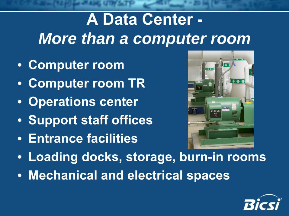
• Computer room• Computer room TR• Operations center• Support staff offices• Entrance facilities• Loading docks, storage, burn-in rooms• Mechanical and electrical spaces
A Data Center - More than a computer room

Data Center Spaces• Entrance Rooms & Access Providers• Main Distribution Area & “edge”
devices• Horizontal Distribution Areas • Telecommunications Room• Racks & Cabinets

Topologies within Data CenterTypical • Single Entrance Room• One or more TRs• Several Horizontal Distribution Areas

Topologies within Data CenterMinimized • Single Main Distribution Area
– Entrance facility– Telecommunications room– Horizontal distribution within data center

Topologies within Data CenterDivergent • Multiple Entrance Rooms• One or more TRs• Multiple Horizontal Distribution Areas
with redundant backbone cabling

Architectural Elements• Size• Equipment: electrical and mechanical• Ceiling heights• Treatments• Lighting• Doors• Floor loading

Data Center Cabling

Cabling Elements• Service provider cables• Backbone cables• Horizontal cables• Zone distribution

Cabling Elements• ANSI/TIA/EIA-568-B.2 still applies!

Cabling Elements• Data center can be a
“building”• Backbones within data
center• Centralized optical
fiber cabling• Horizontal cable
“reduced”• Redundancy

Power Elements• Generators• UPS and batteries• Bonding and
grounding• Power &
environmental monitoring
• Emergency-power- off (EPO)

Mechanical Elements• Cooling operations• Environmental parameters• Fire suppression

Redundancy -
the start of “Tiering”
• Entrance pathways - OSP• Access provider services• Entrance facilities• Main distribution areas (with care)• Backbone cabling• Horizontal cabling• Mechanical and electrical systems

Concurrent Maintainability
Systems can be maintained, upgraded, and tested without impacting normal operations.

Fault Tolerant
System can handle any unplanned failure or planned outage without impacting normal operations including loads on support systems.

Tier 1 -
“N” A starting point
• “Need”
-
Just enough

Tier 1 -
“N”• Architectural
– Plain box

Tier 1 -
“N”• Cabling/Equipment
– Single feeder pathway for access provider– Single entrance room– Single-path distribution– No redundancy

Tier 1 -
“N”• Power
– Single power feeder– UPS - single module or non-redundant
modules– Generator optional– PDU’s may be used

Tier 1 -
“N”• Mechanical
– Single cooling source– Multiple cooling units to need immediate
need– Generator power, if available

Tier 1 -
“N”• “Need”
-
Just enough
• Failure of single unit or disruption for maintenance will disrupt operations

Tier 1

Tier 2 -
“N+1” The start of redundancy
• “Need plus one”
Tier 2 -
“N+1”• Architectural
– Physical protection against disruption, natural and man-made
– Environmental conditioning improvements– Loading dock

Tier 2 -
“N+1”• Cabling/Equipment
– Two feeder pathways for access provider– Single entrance room– Redundant backbone cables within data
center– Critical equipment with redundant
components

Tier 2 -
“N+1”• Power
– Single power feeders with ATS– UPS - redundant UPS modules (N+1)– Generator sized as “N”– Redundant PDU’s, preferably from
separate UPS systems– Dual power cords for all equipment– Grounding Infrastructure

Tier 2 -
“N+1”• Mechanical
– Multiple units plus redundant unit– Single piping pathways– Generator power– Air supplied via raised floor

Tier 2 -
“N+1”• “Need plus one”• Single pathway for systems• Maintenance of critical power will
disrupt operations• Less susceptible to disruption from the
failure of single unit

Tier 1
Tier 2

Tier 3 -
“2N” Doubling up
• Two complete systems for each needed:– One active set of systems– One standby set of systems

Tier 3 -
“2N”• Architectural
– Specific protections against most disruption
– Physical separate of redundant systems– Security checkpoints, access controls,
and fences– Site access improvements– EMI protection– 2 or more loading docks
Tier 3 -
“2N”• Cabling/Equipment
– Two access providers or two points-of- presence
– Redundant backbone cables & pathways within data center
– Hot, standby spare for all critical equipment

Tier 3 -
“2N”• Power
– A mix of “N+1” and “2N”– Dual utility feeders, one active & one
inactive– N+1 redundancy at all component levels– Redundant power to mechanical systems– Generator sized for equipment and
mechanicals plus 1– Any component can be isolated– Power monitoring

Tier 3 -
“2N”• Mechanical
– Fully redundant cooling units– Dual path piping system– Redundant power– Environmental monitoring

Tier 3 -
“2N”• One active, one standby• Redundant pathways, each able to
carry full load• Planned outages of systems without
disruption to service• Unplanned failure of one system
without disruption to service• Susceptible to disruption in
failure/maintenance mode

Tier 1
Tier 2
Tier 3

Tier 4 -
“2(N+1)” Two of everything, all the time
• Two complete systems for each needed:– Two active sets of systems– Each set is N+1

Tier 4 -
“2(N+1)”• Architectural
– Specific protections against all disruption– Secured equipment yard

Tier 4 -
“2(N+1)”• Cabling/Equipment
– Secondary distribution area for redundant routers & switches
– Secondary area isolated from main area for all systems
– Armored cables or conduit pathways– Dual power supplies for electronic
equipment

Tier 4 -
“2(N+1)”• Power
– Utility feeder from two different sub- stations
– Both feeders are active– Primary and reserve UPS systems– Generator sized for building load plus 1

Tier 4 -
“2(N+1)”• Mechanical
– Alternative water storage for evaporative cooling systems

Tier 4 -
“2(N+1)”• Two active, each able to carry full load• Planned outages of systems without
disruption to service• Unplanned failures without disruption
to service• Redundant pathways, • Very limited susceptibility to service
disruptions

Tier 1
Tier 2
Tier 3
Tier 4

Data Center Costs
TierAnnual Outage*
Construction Cost
1 “N” 28.8 hrs $450 / sq. ft.
2 “N+1” 22.0 hrs $600 / sq. ft.
3 “2N” 1.6 hrs $900 / sq. ft.
4 “2(N+1)” 0.8 hrs $1,100 / sq. ft.
* Outage times based on actual field data by The Uptime Institute, Inc.

Growth, a planned cost?• Right-sizing the initial design
– Not too big, not too small• Total Cost of Ownership• Realistic planning for growth

Word of caution
There is no “almost.”
It is only a standard.

A different approach to tiering• A compromise -
Application tiering

A different approach to tiering• A compromise -
Application tiering
• Dual site data center and redundancy

A different approach to tiering• A compromise -
Application tiering
• Dual site data center and redundancy• 1 + 1 = ?

Question• Can you build a Tier 4 data center on a
Tier 1 budget?

Answer• Well …
sort of?

Concluding remarks• TIA-942 provides an excellent basis of
design, not a blueprint for design.• Designers must educate owners.• Designers must consider creative
solutions.• 1 + 1 = 4, but 1$ + 1$ ≠
1$

Questions?
Peter P. Charland III, RCDD/NTS/WD, CET
RTKL Associates Inc. www.rtkl.com