building an effective programme - mettler toledo an effective programme 46 prevention of metal...
TRANSCRIPT

The Metal Detection GuideBuilding an Effective Programme

No part of this manual may be reproduced or transmitted in any form or by any means, electronic or mechanical, including photocopying and recording, for any purpose without the express written permission of Mettler-Toledo Safeline Limited.
This documentation is furnished with restricted rights.
The information contained in this manual is provided to assist producers in developing and implementing an effective metal detection programme.
Mettler-Toledo Safeline Limited does not warrant the accuracy or applicability of the information contained herein and as such is specifically not responsible for property damage and/or personal injury, direct or indirect for damages and/or failures which may be caused as a result of using the information provided.

1© 2016 Mettler-Toledo Safeline Ltd
Contents Page
Introduction 2
Introduction to Metal Detection 6
Key Design Features 12
Factors Limiting Sensitivity 18
Systems Design & Applications 26
Metal Detection, X-ray Inspection or Both Technologies? 36
Reasons For a Metal Detection Programme 42
Building an Effective Programme 46
Prevention of Metal Contamination 48
Selecting Control Points 52
Operating Sensitivity 56
Installation and Commissioning 60
Performance Validation, Verification and Monitoring 64
Dealing With Suspect and Rejected Product 76
Data Analysis and Programme Improvement 80
Data, Connectivity and Improving Performance 84
Calculating Total Cost of Ownership for In-Line Metal Detection Equipment 90
The Principles of Due Diligence For Quality Control and Legal Defence 100
Understanding Challenging Applications for Improved Metal Detection 106
Explosion Protection for Metal Detectors 112

2
Introduction
Most manufacturers and processors in the food and pharmaceutical industries recognise the need for metal detection systems and that they are an essential element of any efficient and effective quality-focused regime. There is an ever greater need for metal detectors in an increasingly competitive market-place driven by a growing range of complex factors including changing customer requirements, the tightening of industry standards, and the growth of regulatory and legislative bodies.
© 2016 Mettler-Toledo Safeline Ltd
However, merely installing metal detectors as stand-alone equipment will not necessarily guarantee the manufacture of products that are free of metal contaminants; metal detector installations need to form part of an effective overall metal detection programme. This updated guide has been rewritten to include the latest changes in technology, industry trends and standards, legislation and regulatory requirements (SLR’s).
An effective metal detection programme can, of course, provide protection against product failure and recalls due to metal contamination. More than that though, an effective metal detection programme can help to maintain hard-won supplier certification status, whilst also reducing overall operating costs.
In the event of a legal claim, an effective metal detection programme can also support proof that reasonable precautions and due diligence have been applied in the manufacturing process.
The requirements for an effective metal detection programme, as well as the benefits of adopting such a programme, are summarised in diagram 1a.

3© 2016 Mettler-Toledo Safeline Ltd
Table 1a: Effective metal detection programme
External Inputs
Effective Metal Detection Programme
Industry Standards Regulatory AuthoritiesCustomer/Industry Consortia
International Standards e.g. ISO 22000
Industry Standards e.g. HACCPSQF 1000/2000 Code
GMP
Food Safety LegislationUSDA
FDA, FSMA, ANVISACertification Bodies
Retail Consortia e.g. GFSI standards BRC, IFS
Retailer CodesBrand Consumer Codes
Producer, Retailer and Consumer Benefits
Reduced Failure Costs Protection Against Product Recall/Claims
Maintain Certification Status
Retailer Confidence
Brand Protection
Reasonable Precautions
Due Diligence Maintain Approved Supplier Status
Metal Detection System Selection1. Introduction to Metal Detection2. Key Design Features3. Factors Limiting Sensitivity4. Systems Design & Applications5. Metal Detection, X-ray Inspection or Both Technologies?
Building an Effective Programme6. Reasons For a Metal Detection Programme7. Building an Effective Programme8. Prevention of Metal Contamination9. Selecting Control Points10. Operating Sensitivity11. Installation and Commissioning12. Performance Validation, Verification and Monitoring13. Dealing With Suspect and Rejected Product14. Data Analysis and Programme Improvement15. Data, Connectivity and Improving Performance16. Calculating Total Cost of Ownership for In-Line Metal Detection Equipment17. The Principles of Due Diligence For Quality Control and Legal Defence18. Understanding Challenging Applications for Improved Metal Detection19. Explosion Protection for Metal Detectors

4
Introduction
© 2016 Mettler-Toledo Safeline Ltd
This guide provides a comprehensive reference source for those involved in food safety, and provides an insight into all aspects of metal detection, from basic principles through to implementing a comprehensive metal detection programme.
Chapters 1 to 4 provide an overview of how metal detectors work, together with an explanation of important design features. These chapters also offer an insight into factors which potentially limit performance of the equipment. There is also a description of the integration of metal detectors with effective rejection systems.
Chapter 5 gives consideration to how both metal detection and x-ray inspection systems could be used separately or together to provide the maximum protection against an increased range of possible contamination materials.
Chapters 6 to 15 demonstrate that simply installing a metal detection system alone will not necessarily provide adequate levels of protection against metal contamination. For proper and thorough protection, a comprehensive metal detection programme is required – and the key elements of such a programme are explained here in detail.
Chapter 16 to 19 offer practical guidance including some thoughts on how to calculate the total cost of in-line metal detection ownership and a description of how through better system due diligence food industry standards can be exceeded. The penultimate chapter considers how to overcome challenging food applications using the latest in-line metal detection systems. The final chapter explains explosion protection.

5
Introduction
© 2016 Mettler-Toledo Safeline Ltd
Notes

6
1
1 Introduction to Metal Detection
Introduction to Metal Detection
This chapter provides a broad overview of components and operating principles, so as to communicate an overall understanding of metal detection systems.
The information in this chapter can then be built upon, based on the information in subsequent chapters - and this should lead to a clear understanding of metal detection technology, equipment capabilities and performance.
1.1 Sources of Metal Contamination
1.2 What is a Metal Detection System?
1.3 Where Can a Metal Detection System Be Used?
1.4 Balanced Coil System
1.5 Ferrous-in-Foil (FIF) Detection
1.6 Detection Modes
1.7 Why Should you Choose the Correct Metal Detector?
© 2016 Mettler-Toledo Safeline Ltd
1.1 Sources of Metal ContaminationMetal contamination sources are numerous – and even the most stringent controls cannot prevent the occasional incident in which small pieces of metal find their way into products destined for consumer consumption.
Good working practices will minimise the likelihood of metal contaminants entering the production flow; furthermore, correct equipment design and appropriate selection will maximise the likelihood of reliably detecting and rejecting any metal particles that have found their way into products.
Contamination normally comes from the following sources:• Raw Materials
Typical examples include metal tags and lead shot in meat; wire in wheat; screen wire in powder material; tractor parts in vegetables; hooks in fish; staples; wire strapping from material containers.
• Personal Effects Buttons; pens; jewellery; coins; keys; hair-clips; thumb-tacks; pins; paper clips, etc.
• Maintenance Screwdrivers and similar tools; swarf and welding slag (following repairs); copper wire off-cuts (following electrical repairs); miscellaneous items resulting from inefficient clean-up or carelessness; metal shavings from pipe repair.
• In-plant Processing The danger of contamination exists every time the product is handled or passes through a process. Crushers, mixers, blenders, slicers and transport systems can all act as sources of metal contamination. Examples of metal contamination from these sources include broken screens, metal slivers from milling machines, and foil from reclaimed products.
Identifying the likely source of contamination is a vitally important stage in developing a successful overall metal detection programme.

7© 2016 Mettler-Toledo Safeline Ltd
1.2 What is a Metal Detection System?An industrial metal detection system is a sophisticated piece of equipment used to detect and reject unwanted metal contamination. When properly installed and operated, it helps to reduce metal contamination and improve food safety. A typical metal detection system consists of four main parts:
1. Detector Coil or ‘Detector Head’Most modern metal detectors fall into one of two main categories, with respect to the ‘Detector Head’, which is that part of the metal detector system that identifies the presence of metal contamination: • The first type of metal detector utilises a ‘balanced coil’
Detector Head. Detectors of this design are capable of detecting all metal contaminant types, including ferrous, non-ferrous and stainless steels, in fresh and frozen products. The products being inspected can be either unwrapped or wrapped, and can include products wrapped in metallised films.
• The second detector type utilises permanent magnets in a ‘Ferrous-In-Foil’ Detector Head. These Detector Heads are capable of detecting ferrous metals and magnetic stainless steels only within fresh or frozen products which are packed in an aluminium foil wrapping.
Whilst it is recognised that other technologies exist, this guide concentrates mainly on the ‘balanced coil’ detector type − and (to a much lesser extent) on Ferrous-In-Foil (FIF) technologies.
Detector Heads can be manufactured in virtually any size, in order to suit the product being inspected. They may be rectangular or round, and may be mounted horizontally, vertically or on an incline.
Each Detector Head has an opening (known as an ‘aperture’) through which product passes. When a metal contaminant is detected by the detector Detector Head, a signal is sent to the electronic control system.
2. User Interface/Control PanelThe user interface is the front-end of the electronic control system, and is often mounted directly on the Detector Head. However, the user interface can be mounted remotely (with connecting cables) if the Detector Head is too small, or if the Detector Head is installed in an inconvenient or inaccessible location.
3. Transport SystemThe transport system is used to pass the product to be inspected through the aperture of the metal detector. The most common type of transport system is a conveyor. Alternatives include:• A plastic chute with the detector mounted on an incline• A non-metallic pipe, mounted horizontally or vertically.
This type of transport system is commonly used in the inspection of powders and liquids
4. Automatic Rejection SystemAn automatic reject device is frequently fitted to the transport system in order to remove any contaminated product from the production line. There are many different styles available including ‘air blasts’, ‘push arms’, ‘drop flaps’, etc. The style of the reject device installed will depend on the type of product being inspected (Refer to Chapter 4 for further information).
In addition to the four main parts of a metal detection system, other important items may include:• A lockable container fixed to the side of the conveyor, to
collect and hold rejected product• A full-length cover between detector and reject device• A fail safe alarm which operates if the metal detector
develops a fault• A reject confirmation device, with sensors and timers,
to confirm that contaminated product is actually rejected from the line
• A beacon and/or audible alarm that alerts operators to various other events, such as an automated warning that a detector is due to be tested or that the reject bin is full
• Numerous optional fail safe systems to raise level of “Due Diligence”
1.3 Where Can a Metal Detection System Be Used?Metal detectors may be used at various stages of a production process:
1. Bulk ‘In-Process’ Inspection• Eliminates metal before it can be broken into
smaller pieces• Protects processing machinery from damage• Avoids product and packaging waste by subsequently
rejecting a finished higher-value product
Typical examples include bulk inspection of meat blocks prior to grinding, ingredients for pizza toppings and grain products.
2. Finished Product Inspection• No danger of subsequent contamination• Ensures compliance with retailer and consumer brand
quality standards
A combination of bulk and finished product inspection will provide optimum protection.
The most common types of metallic contamination include:• Ferrous (iron)• Non-ferrous (brass, copper, aluminium, lead)• Various types of stainless steel (magnetic and
non-magnetic
Of the three types listed above, ferrous metal is generally the easiest to detect − and relatively simple detectors (or even magnetic separators) can perform this task well.
Stainless steel alloys are extensively used in the food industry, but are often the most difficult to detect, especially common non-magnetic grades such as 316 and 304.

8
Introduction to Metal Detection1
© 2016 Mettler-Toledo Safeline Ltd
Non-ferrous metals, such as brass, copper, aluminium and lead, usually fall between these two extremes, although in larger metal detectors operated at higher frequencies, non-ferrous metal may be harder to find than non-magnetic stainless steel.
Only metal detectors using an alternating current ‘balanced coil’ system have the capability to detect small particles of non-ferrous and non-magnetic stainless steel.
1.4 Balanced Coil System1.4.1 Basic Principles of OperationThree coils are wound onto a non-metallic frame or ‘former’, and each coil is exactly parallel with the other two (Figure 1.1). The centre coil (the ‘transmitter’) is energised with a high-frequency electric current that generates a magnetic field.
The two coils on each side of the centre coil act as receivers. Since these two coils are identical and are the same distance from the transmitter, an identical voltage is induced in each. When the coils are connected in opposition, these voltages cancel out, resulting in ‘zero output’.
The control electronics actually split the received signal into two separate components; these are known as ‘magnetic’ and ‘conductive’, and are at 90º to each other.
To prevent airborne electrical signals, or to prevent nearby metal items and machinery from disturbing the detector, the complete coil arrangement is mounted inside a metal case. This has an opening (‘aperture’) to allow passage of the product.
The case can be constructed of aluminium or stainless steel (depending on application). In addition to creating a screen, the metal case adds strength and rigidity to the assembly. This is crucial for satisfactory operation of the detector.
Several special mechanical and electrical techniques are essential to the design of stable, reliable metal detectors. On-line production stability overtime is a key measure of a metal detector’s performance when comparing one suppliers offering to another.
1.4.2 Mechanical TechniquesThe metal case affects the magnetic field’s state of balance, and any movement relative to the coils can cause a false detection signal. In addition, microscopic movements of the coils relative to each other (as small as 1 micron), can cause a signal sufficient to result in a false rejection.
One of the major design problems for metal detector manufacturers is to devise a totally rigid and stable system, unaffected by vibration from motors, pulleys, auto-reject devices, temperature changes, transportation and machinery located in close proximity.
It is vitally important to select the right kind of material for detector head coil specifications and case design are equally crucial. To increase mechanical rigidity further, most manufacturers fill the detector case with a material to prevent relative movement of the metal case to the coils (frequently referred to as ‘potting’).
This helps produce a unit that is able to operate at maximum sensitivity under typical factory conditions. The quality of the potting is critical to the performance of the metal detector.
Figure 1.2
Output
Receiver
Transmitter
Product Flow
Receiver
Figure 1.1
Product Flow
Receiver Receiver
Output
Transmitter
Encircling Coil(Cut-away)Encircling Coil(Cut-away)
As a particle of metal passes through the coil arrangement, the high-frequency field is disturbed at the 1st receiver coil (point A) and then at the 2nd receiver coil (point B). This action changes the voltage generated in each receiver (though by a matter of only 1x10⁻⁹ nano-volts). Despite the very small change in voltage, this alteration in balance generates a signal that can be processed, amplified and subsequently used to detect the presence of unwanted metal (Figure 1.2).

9
Introduction to Metal Detection1
© 2016 Mettler-Toledo Safeline Ltd
1.4.3 Electronic TechniquesMechanical construction methods will minimise false signals from coil and case movements; they will also provide long-term stability in harsh environments. However, various factors can contribute to an out-of-balance voltage. These include:• Temperature changes• Metal close to the aperture• Ageing of electronic components• Slow changes in the mechanical structure
These types of factors that create out-of-balance voltage can be eliminated by various electronic techniques. Automatic Balance Control continuously monitors out-of-balance voltage and automatically corrects it. This removes the need for periodic fine-tuning by an operator, and ensures that the detector is always operating at the optimum level.
Quartz Crystal Control, now standard on most metal detectors, accurately controls the frequency of the oscillator in order to prevent ‘drift‘. However, further electronic compensation is necessary to combat electronic component changes which occur with changes in temperature.
Automatic Balance Control and Quartz Crystal Control will not, themselves, enable the detector to detect smaller pieces of metal. They will, however, enable the detector to permanently maintain this level of sensitivity without operator attention and without the generation of false reject signals.
Temperature compensation control circuitry automation manages the effects of external temperatures variation that may effect the performance of the detector by eliminating balance drift.
For high performance over an extended period, Automatic Balance Control, Quartz Control, temperature compensation and ‘potting’ of Detector Heads are all essential.
1.4.4 Metal Free Zone (MFZ)Most of the detector’s high-frequency magnetic field is contained within the metal case of the detector unit. There is some unavoidable leakage of the magnetic field from the aperture of the detector – and it is the effect of this leakage on the magnetic field of the surrounding metalwork that may influence the detector’s performance, resulting in inconsistencies in detection capability.
To achieve optimum metal detection results, the aperture of the detector should be surrounded by an area known as the ‘Metal-Free Zone’ or ‘MFZ’; this area should be kept free of all metals.
The size of the MFZ is dependent upon:• The aperture size (Figure 1.3)• The type of detector• The operating sensitivity
Stationary metal can be positioned closer to the detector than moving metal.
The MFZ will normally be specified within the manufacturer’s installation instructions. Typical quoted values are in the region of 1.5 x aperture height for stationary metal and 2.0 x aperture height for moving metal. Due consideration of this during installation will provide consistent, reliable metal detection performance.
Space may be restricted, as where a short conveyor system is used, or when installation is between a weighing machine and a vertical form-fill seal bag maker. Under these circumstances, a special unit may need to be used if the metal-free zone is unduly small. This is referred to as ‘Zero Metal-Free Zone (ZMFZ) technology. Alternatively there are some mechanical techniques, such as the additional of extended flanges that also attempt to control the leakage of the magnetic field.
1.5 Ferrous-in-Foil (FIF) DetectionWhen the product to be inspected is packaged inside an aluminium foil pack or dish, a metal detector using a balanced coil system cannot be used. However, there is an available detector design which suppresses the effect of the aluminium foil, but is still sensitive to small pieces of ferrous and magnetic stainless steel contamination. Figures 1.4 and 1.5 show the basic operating principle.
MFZ
MFZ
MFZMFZ
Figure 1.3
Output
Product Flow
Figure 1.5
Magnets
Magnets
Output
Product Flow
Figure 1.4
Magnets
Ferrous in Foil detector
MagnetsMagnets
Magnets
Ferrous in Foil detector
MFZ
MFZMFZMFZ
10
Introduction to Metal Detection1
© 2016 Mettler-Toledo Safeline Ltd
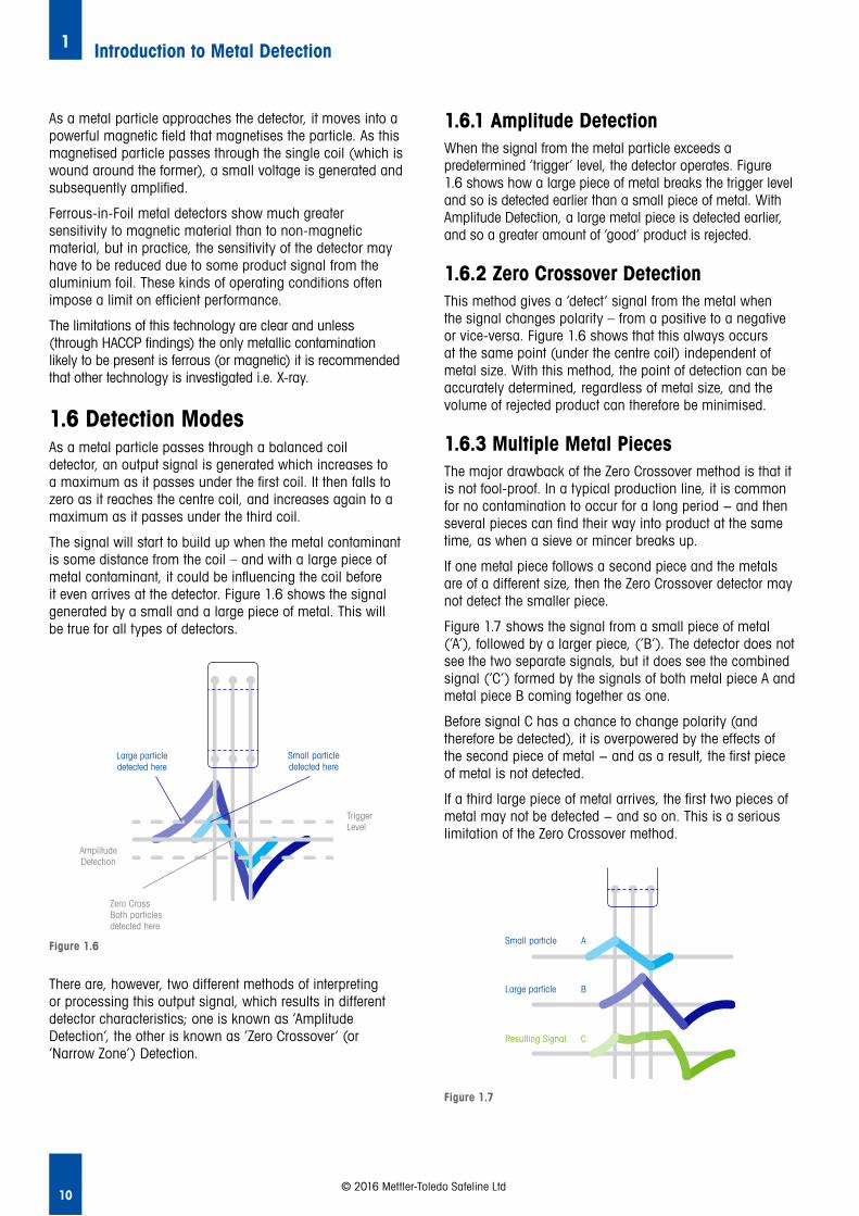
There are, however, two different methods of interpreting or processing this output signal, which results in different detector characteristics; one is known as ‘Amplitude Detection’, the other is known as ‘Zero Crossover’ (or ‘Narrow Zone’) Detection.
1.6.1 Amplitude Detection When the signal from the metal particle exceeds a predetermined ‘trigger’ level, the detector operates. Figure 1.6 shows how a large piece of metal breaks the trigger level and so is detected earlier than a small piece of metal. With Amplitude Detection, a large metal piece is detected earlier, and so a greater amount of ‘good’ product is rejected.
1.6.2 Zero Crossover Detection This method gives a ‘detect’ signal from the metal when the signal changes polarity – from a positive to a negative or vice-versa. Figure 1.6 shows that this always occurs at the same point (under the centre coil) independent of metal size. With this method, the point of detection can be accurately determined, regardless of metal size, and the volume of rejected product can therefore be minimised.
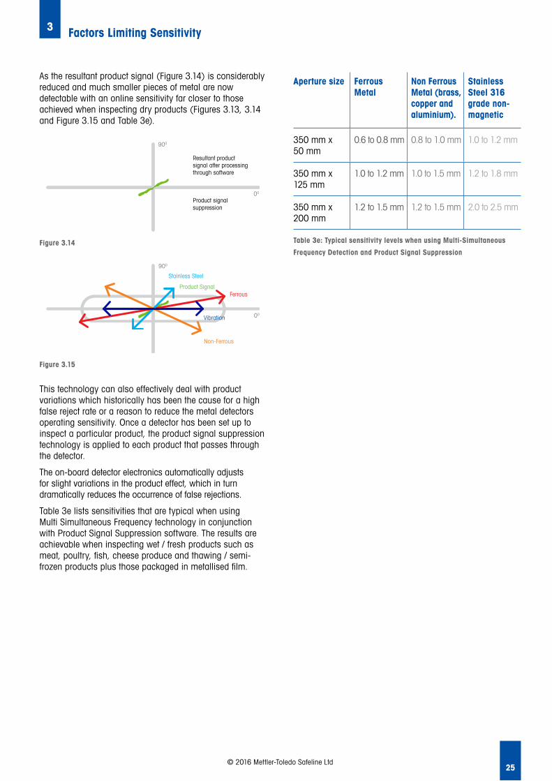
1.6.3 Multiple Metal PiecesThe major drawback of the Zero Crossover method is that it is not fool-proof. In a typical production line, it is common for no contamination to occur for a long period − and then several pieces can find their way into product at the same time, as when a sieve or mincer breaks up.
If one metal piece follows a second piece and the metals are of a different size, then the Zero Crossover detector may not detect the smaller piece.
Figure 1.7 shows the signal from a small piece of metal (‘A’), followed by a larger piece, (‘B’). The detector does not see the two separate signals, but it does see the combined signal (‘C’) formed by the signals of both metal piece A and metal piece B coming together as one.
Before signal C has a chance to change polarity (and therefore be detected), it is overpowered by the effects of the second piece of metal − and as a result, the first piece of metal is not detected.
If a third large piece of metal arrives, the first two pieces of metal may not be detected − and so on. This is a serious limitation of the Zero Crossover method.
AmplitudeDetection
Large particledetected here
Small particledetected here
Zero CrossBoth particlesdetected here
TriggerLevel
Figure 1.6
Zero Cross Both particles detected here
Large particledetected here
AmplitudeDetection
Small particledetected here
TriggerLevel
A
B
C
Small particle
Large particle
Resulting Signal
Figure 1.7
Small particle A
B
C
Large particle
Resulting Signal
As a metal particle approaches the detector, it moves into a powerful magnetic field that magnetises the particle. As this magnetised particle passes through the single coil (which is wound around the former), a small voltage is generated and subsequently amplified.
Ferrous-in-Foil metal detectors show much greater sensitivity to magnetic material than to non-magnetic material, but in practice, the sensitivity of the detector may have to be reduced due to some product signal from the aluminium foil. These kinds of operating conditions often impose a limit on efficient performance.
The limitations of this technology are clear and unless (through HACCP findings) the only metallic contamination likely to be present is ferrous (or magnetic) it is recommended that other technology is investigated i.e. X-ray.
1.6 Detection ModesAs a metal particle passes through a balanced coil detector, an output signal is generated which increases to a maximum as it passes under the first coil. It then falls to zero as it reaches the centre coil, and increases again to a maximum as it passes under the third coil.
The signal will start to build up when the metal contaminant is some distance from the coil – and with a large piece of metal contaminant, it could be influencing the coil before it even arrives at the detector. Figure 1.6 shows the signal generated by a small and a large piece of metal. This will be true for all types of detectors.

11
Introduction to Metal Detection1
© 2016 Mettler-Toledo Safeline Ltd
1.6.4 Inverse DetectionSome packaged products deliberately include a metal object as part of the packaging or part of the product itself. This might be a specific component or a free gift – but whatever its form or function, metal detectors can also be used to verify that such a ‘required‘ metal object is present in a packaged product.
This is usually achieved by reversing the action of the reject timer so that product containing no metal is rejected, whilst product containing metal is accepted.
With this type of application, it is important to monitor the product both before and after the time at which the metal item is introduced. This will ascertain that the detected metal item at the output point is the ‘required‘ object and not a metal contaminant.
1.7 Why Should you Choose the Correct Metal Detector? 1.7.1 ComplianceWhen installed at critical control points (CCP’s) in your processes, metal detectors enable your business to comply with the requirements of Hazard Analysis and Critical Control Points (HACCP) and the broader needs of food safety regulations and standards. (Refer to Chapter 9 for further information).
However, it is not enough to simply install a metal detector at critical control points. Regular testing of the performance of metal detection equipment is an essential part of any well designed quality management system in the food and pharmaceutical industry.
1.7.2 Cost ReductionSelecting the most stable and reliable metal detector, and installing it at the most appropriate point(s) within the manufacturing process enables overall lifetime costs to be managed and kept to an absolute minimum through:• Eliminating false rejects and product waste• Reducing performance testing requirements
1.7.3 Productivity ImprovementsResearch suggests that on average, plants waste between 28% up to 40% of their capacity through stops, speed losses, interruptions and defects. Choosing a metal detector that is simple to set up and operate, offers reliable and consistent performance, with low maintenance requirements and easy-clean system design can enable productivity to be optimised by ensuring costly downtime is all but eliminated.
Overall Equipment Effectiveness (OEE) is an important tool in the pharmaceutical, packaging and food processing industries. In any capital intensive business OEE improvement is a critical methodology to drive improved efficiency, higher quality and reduced cost.
Adopting OEE methodology can provide benefits in the following areas:• Equipment: Reduced equipment down-time and
maintenance costs, and better management of the equipment life cycle
• Personnel: Labour efficiencies and increased productivity by improving visibility into operations and empowering operators
• Process: Increased productivity by identifying bottlenecks• Quality: Increased rate of quality and reduced scrap.
A number of software tools exist to capture manufacturing performance data and display OEE performance graphically. Selection of an appropriate OEE software tool is critical to the success of any OEE initiative. A mistake to be avoided is the belief that this tool will drive OEE improvement − remember that any OEE software application is just a tool, and if not harnessed correctly will merely measure OEE, not improve it. Refer to Chapter 15 for more detailed information regarding measuring and calculating OEE, and guidance on how it can be improved.
1.7.4 Improved CompetitivenessUltimately, by complying with regulatory, industry and retailer standards, reducing your costs and increasingly your productivity you can improve your competitiveness. This in turn enables you to protect your brand and your reputation and be in a better position to win more customers.

12
2
2. Key Design Features
Key Design Features
In the event of a metal detector failure at a manufacturing facility, the manufacturer may well face a dilemma: production must either halt until a service engineer visit can be scheduled - or the production line can continue to run, but with the risk of metal contamination going undetected.
The chances of having to face this dilemma can be significantly reduced by choosing the most reliable metal detection system available. This chapter provides valuable information on some of the key considerations and design features to bear in mind when selecting the best metal detection system for a particular manufacturing environment.
2.1 Detector Electronics Design
2.2 Detector Mechanical Design
2.3 Conveyor System Design
2.4 Non-Conveyorised System Design
2.5 Reject Mechanism Design
2.6 Hygienic Design
2.7 Health and Safety
2.8 Fail Safe System Design
© 2016 Mettler-Toledo Safeline Ltd
Selecting a reliable metal detection system is a major step towards minimising (or even eliminating) the occurrence of metal contamination within products being manufactured on a production line. However, despite the widespread use of metal detectors, there are few guidelines available to help users evaluate the advantages of a particular detector or compare the capabilities of different brands of machines.
Drift, erratic detection, complexity of set-up, and random false rejects are the types of metal detector faults that can have major negative impacts on the overall success of a metal detection programme. And of course, when metal detectors are subject to such faults, metal detectors can be frustrating to production personnel.
Unsurprisingly, such personnel are soon likely to lose confidence in a metal detection system that rejects product which is subsequently shown to be good. Equally frustrating to production operatives is a metal detection system that requires constant attention in order to maintain appropriate sensitivity standards.
A metal detection system that is capable of giving consistent, reliable detection and rejection, without the frustration of false rejection, will win the confidence of both line operators and management. It will also provide the best long-term protection for products, the brand, and the manufacturer.

13© 2016 Mettler-Toledo Safeline Ltd
2.1 Detector Electronics DesignModern metal detectors benefit from advanced digital processing technology, which means that they can provide a wide range of features at relatively little cost. However, a large number of features will not necessarily contribute to a metal detector’s overall effectiveness.
The danger is that those new to metal detection may draw up a checklist of desired metal detector features, and then make comparisons between different brands. They may then make an assumption that the brand with the longest list of features is the best choice of metal detector for their purposes.
Those new to metal detectors may also believe that the greater the sensitivity, the more effective the unit is likely to be – and they will use such criteria as a basis to evaluate and compare different systems.
Judging a metal detector simply by its range of features and/or its sensitivity levels alone is not the right approach when choosing an appropriate system. Users with more experience will know that, whilst sensitivity is important, it is only one of several key factors that should be borne in mind in the selection process.
2.1.1 StabilityStability is the distinguishing factor of a top-quality metal detector, and highlights the difference between sensitivity and performance. In this context, ‘performance’ is a measure of equipment capability under real plant conditions.
A stable metal detector can operate consistently without false rejects or erratic detections, and should not require periodic adjustment. Most digital processing controlled units will give similar sensitivity levels when tested side by side under laboratory conditions; however, over extended operation on a production line, significant differences may well become evident.
An unstable detector, particularly when linked to an automatic reject device, can quickly attract criticism due to its inefficient performance.
2.1.2 Electronic DriftElectronic drift is a common cause of instability, and occurs over a period of time as a result of temperature variations and the ageing of electronic components. These factors can result in changing sensitivities (‘drift’), which may well lead to false alarms or unwanted signals.
Frequency and phase stability of highly-tuned electronic circuits within the metal detector are key to minimising electronic drift – and the degree of stability required becomes increasingly important as the level of sensitivity is increased.
Design features such as Quartz Frequency Control, Automatic Temperature Stability Control and Auto Balance Control will make a major contribution to eliminating drift – and this will help to ensure that the correct system sensitivities are permanently maintained.
2.1.3 RepeatabilityIn addition to false rejections, drift can cause the detection level to vary over time. However, a detector that detects a test sample repeatedly each time it is used (over a period of weeks or months) will instil confidence in the user.
A detector demonstrating such high levels of reliability also avoids the problems of having to re-inspect product; a reliable metal detector will identify metal contaminants and will also prevent them passing undetected on the production line.
2.1.4 Ease of Set-up and Use If a detector has a complex or confusing set-up procedure, it is likely that it will not be adjusted correctly. Set-up should be a simple and straightforward matter − and after initial instruction, the user should be able to adjust all parameters without reference to an instruction manual.
Together, a logical set-up procedure and an intuitive Human Machine Interface (HMI) avoid having to memorise special sequences; these two factors also permit changes to be made in the correct manner long after initial training is given.
Several detector brands promote ‘automatic set-up’ features; however, actual ease of operation needs to be considered in conjunction with the accuracy and ease of the initial set-up. The most modern detectors may include visual representations of complex product signals, which can greatly aid user understanding and the auto-set-up process.
It is of great benefit if a metal detector can deliver an automatic set-up of a similar standard to that which could be achieved by an experienced user. If this is not the case, there may be a significant loss in detection performance. Metal detectors can be set up on a single pass of a single product but a set-up taken over many passes of many products will be more representative of actual production conditions. Leading detector brands now employ software algorithms that deliver automatic setup equivalent to experienced operator level set up.
The more product settings that there are, the more likely it is that an operator will select the wrong setting for a given product. So in order to minimise the number of product settings necessary, some detectors include features that group similar products together and establish a common setting.
The benefit of such groupings is the ease with which the systems can be operated and the accuracy of the set-up, The latest Multi-Simultaneous Frequency (MSF) detectors have taken this a step further and can provide a single product setting on which significantly different products can be inspected at sensitivity levels in excess of conventional single, dual or triple frequency counterparts.

14
Key Design Features2
© 2016 Mettler-Toledo Safeline Ltd
2.1.5 Electrical Noise and Radio Frequency Immunity (RFI)If the metal detector does not incorporate design features with a high degree of Electrical Noise and Radio Frequency Immunity, the system will be vulnerable to false triggers that will ultimately lead to a loss of confidence by production-line employees; it will also waste time and money through investigation of false product rejections.
In the manufacturing environment, there are numerous Radio Frequency Interference sources, such as fluorescent lighting, mobile devices, inverter (and variable frequency) drives etc. These kinds of items all have the potential to interfere with the operation of metal detection systems.
2.1.6 Modular ElectronicsSome metal detectors incorporate a universal quick-change electronic module, which is designed for change-out (i.e. replacement of malfunctioning or obsolete part with a replacement part).
One of the main benefits of such a module is that it can help to reduce service costs and keep lost production time to a minimum during maintenance and/or repair procedures.
On production lines where downtime is unacceptable, it is important to use detectors with a single electronic module designed for user change-out.
2.1.7 Self-Checking and Condition MonitoringWith ever greater emphasis on improving uptime, production efficiency (OEE), many producers are now focusing on reducing downtime, whilst also trying to reduce the burden of scheduled testing.
Metal detection systems with self-checking and continuous condition monitoring features can offer significant benefits by providing early warning of a potential system failure. Such systems allow preventive action to be implemented, rather than depending on reactive maintenance and frequent testing.
In considering the usefulness of such features, it is important that the key parameters are continuously monitored through the actual working circuitry of the detector, regardless of whether signals are processed sequentially or in parallel.
It is also important that the system should automatically alert users via an early warning when there has been an unexpected change. Furthermore, the system should trigger an alarm if there is an unacceptable change in the parameters being monitored.
2.2 Detector Mechanical Design2.2.1 Environmental ProtectionThe selection of the metal detector should be commensurate with the hygiene requirements of the product and the environment in which it will operate. If the product is high-risk, the metal detector should be constructed to withstand harsh conditions, deep cleaning and sterilisation routines.
For producers of meat, poultry, dairy and similar products, a metal detector’s inability to withstand frequent heavy duty wash down is a common problem. Single piece liners with no exposed joints are ideal. The repair of a metal detector suffering from water ingress is both expensive and time-consuming.
Providing the conditions are communicated to the metal detection system-provider prior to purchase, system performance should remain unaffected when equipment is situated in any areas subject to water or steam.
If a metal detection system is to be used in an officially designated potentially explosive environment, (such as a flour mill), the system design should be independently certified by an accredited recognised body. Furthermore, the detector manufacturer should be officially approved to make and sell such systems.
2.2.2 Balance Stability and Vibration ImmunityMost metal detectors operate on the basic principle of the balanced coil system. Consequently, maintaining mechanical stability is important to the ongoing performance of the metal detector.
Very small movements in mechanical construction (such as expansion due to temperature, mechanical shock, vibration etc.) can cause a coil system imbalance that may cause the metal detector to false-trigger, drift or go out of balance.
To address these problems, mechanical design and construction should be equally as important as electronics design and construction in preventing and compensating for such movements.
Systems prone to vibration, or which require regular manual balancing, are of little value on an automated production line. Good electronics design (such as Automatic Balance Control), and good mechanical design (such as enhanced potting techniques) go a long way to minimising these potential failure modes.

15
Key Design Features2
© 2016 Mettler-Toledo Safeline Ltd
2.3 Conveyor System Design The design of the conveyor system that transports the product through the detector must meet certain strict criteria if it is to avoid interfering with the detector in any way.
A metal detector conveyor is much more than a modified transport conveyor; the design of both conveyor and auto-reject device will have a major impact on the effectiveness of the overall metal detection programme.
Unless special precautions and design techniques are incorporated, the metal detector can become unstable due to eddy currents in the frame or static build up from the conveyor belt. These can influence the detector, causing interference and a downgrading of sensitivity.
Metal detectors emit a high-frequency signal which causes tiny eddy currents to flow all around the metal structure of the conveyor. These eddy currents have no effect on the detector if they remain constant; however, if the conveyor structure has an intermittent joint of variable resistance (even at a remote distance from the detector), the eddy currents change. This creates an intermittent signal that can be then picked up by the detector and result in a false trigger.
Typical sources of eddy current loops are any intermittent metal-to-metal contact such as bolted conveyor assemblies non-insulated supports, pulley shafts and bearings, chain drives and guards, reject supports and metal conduit clamps.
To obtain the best and most reliable performance, fully welded structures are required. These should incorporate: • Correct metal-free zones• Properly insulated rollers and pulleys• Fully welded cross-structures• Insulated detector head mountings
Conveyor belting materials should be metal-free and manufactured to a very high standard, using suitable contaminant-free joints. Anti-static belting materials should be avoided.
If these problems are not solved at source, the common outcome is a gradual increase in false rejects. The easy (but generally unacceptable) solution is to reduce the sensitivity of the detector. However, this could result in contravention of the sensitivity standards that have been specified.
Effective conveyor design considerations, product transfer methods and recommended types of belts are covered in greater detail in Chapter 4.
2.4 Non-Conveyorised System DesignSimilar considerations should be given to the design of metal detection systems which do not incorporate conveyor systems. These include systems for the inspection of bulk dry powders and granular products, vertical packaging applications, and pipeline systems used for liquids, pastes and slurries.
Incorrectly designed support structures and reject devices will have a major negative impact on overall metal detector system performance, resulting in reduction of the metal detection programme’s effectiveness.
2.5 Reject Mechanism DesignIneffective reject systems are probably the weakest part of most detection systems, and result in metal-contaminated items not being effectively and reliably rejected from the production line. A correctly specified system should be fool-proof and capable of rejecting all contaminated product under all circumstances, no matter how frequent the occurrence, and no matter what the location of the metal within the product. (Refer to Chapter 4 for further information).
2.6 Hygienic DesignAll metal detection systems should be designed with due consideration of the environment in which they will operate. They should also be designed so as to take into account cleaning regimes likely to be encountered.
Hygienic design principles should be applied to every aspect of the system, with the aim of eliminating dirt traps and ensuring easy cleaning, so design features should include:• Elimination of cavities/bacterial traps• Sealing of all hollow sections• Avoidance of ledges and horizontal surfaces• Use of open-design continuous-welded frames for easy
access and cleaning• Hygienic management of electrical cables, trunking and
pneumatic services

16
Key Design Features2
© 2016 Mettler-Toledo Safeline Ltd
2.7 Health and SafetyHealth and Safety is an important consideration, so design and build of metal detection systems should be certified as being in accordance with statutory regulations and standards in force at the time of sale.
For example, CE marking in relation to applicable machinery safety standards will minimise the risk of an employee being hurt. Any such injuries could result in costly personal injury claims.
2.8 Fail Safe System DesignConsideration should be given to the implications of a system failing to function as intended; for example, a reject device not removing contaminated product or a fault occurring within the metal detector.
It is good practice to integrate fail safe design features into the metal detection system, so as to mitigate the risks associated with system malfunction. For example:• Reject confirmation systems can confirm that the
contaminated product has been rejected into the reject bin• In-built condition monitoring systems can be used
to provide early warning of a change in the state or performance characteristics of the metal detector
The numerous aspects of fail safe design that need to be considered are covered throughout this guide. The following list is provided as a quick reference guide to finding such information.
Relevant sections: 1.2, 4.1.9, 4.2, 4.3.1, 4.4.6, 4.5.3, 9.3, 12.2, 12.6.2, 12.7.2, 12.10, 13.2, 14.2.4

17
Key Design Features2
© 2016 Mettler-Toledo Safeline Ltd
Notes

18
3
3 Factors Limiting Sensitivity
3.1 Factors Limiting Sensitivity
3.2 Types of Metal
3.3 Shape of Metal and Orientation Effect
3.4 Aperture Dimension / Position of Metal in Aperture
3.5 Environmental Conditions
3.6 Inspection Speed
3.7 Inspecting Dry Non Conductive Products
3.8 Wet Product Inspection - a Detailed Look
3.9 Automatic Product Compensation
3.10 Product Signal Suppression
Factors Limiting Sensitivity
There is often widespread confusion and misinformation regarding metal detector sensitivity specifications and operating capabilities. Many factors can influence sensitivity performance, and if sensitivity data is to be meaningful, there needs to be certainty that it is correct and accurate within its area of application. This chapter highlights factors that need to be considered in order to ensure that newly-purchased metal detector systems provide the right levels of sensitivity, whilst also delivering proper performance in accordance with operational needs.
© 2016 Mettler-Toledo Safeline Ltd
3.1 Factors Limiting Sensitivity In most markets, sensitivity performance is usually expressed in terms of the diameter of a sphere made from a specific type of metal.
This sphere must be reliably detectable when placed in the centre of the aperture of the metal detector. Precision metal spheres are used for this purpose because they are readily available in a range of metals and diameters.
In addition, they have a consistently spherical shape, regardless of how they are presented to the detector. This means that they have no ‘orientation effect‘. (See section 3.3 for more details).
Japanese metal detector manufacturers state sensitivity performance using similar spheres and materials; however, these spheres are often measured on the conveyor belt and not in the centre of the detector’s aperture. Using this form of measurement, the sphere will be closer to the aperture wall which offers increased sensitivity levels (covered later in this chapter), so higher rates of sensitivity could be observed when compared to differing methods, which measures centre of aperture or worst-case sensitivity performance.
When comparing the performance of metal detectors, it is therefore important to ensure that the sensitivity of the machines is being measured in the same way.
Many factors influence the actual operating sensitivity at which a metal detector is able to reliably perform. These include:• Type of metal • Shape and orientation of metal• Aperture size/metal position in the aperture• Environmental conditions• Inspection speed• Product characteristics and operating frequency
For these reasons, care needs to be exercised when comparing metal detectors based only on the information contained in a specification or within promotional literature.

19© 2016 Mettler-Toledo Safeline Ltd
The information contained within a specification may not be capable of being reliably achieved once the metal detector is installed in the intended application and operating environment. That’s why sensitivity performance-testing under controlled laboratory conditions is not regarded as a good indicator of actual achievable performance.
Actual product testing ‘in situ‘ is essential in order to determine the production-line sensitivity of a metal detector. Therefore in-line factory tests need to be undertaken to ensure that any officially quoted sensitivity performance figures are repeatable, without the possibility of false rejecting in the intended application and operating environment.
3.2 Types of Metal Metals can generally be categorised as being either ferrous, non-ferrous or stainless steel. The sensitivity of a metal detector will vary dependent upon the type of metal contaminant present. The ease of detection depends on the magnetic permeability of the metal contaminant (i.e. how easily it is magnetised), as well as the electrical conductivity of the metal contaminant.
If the contamination is of ferrous metal, then it is both magnetic and a good electrical conductor, so it will be easily detected. Non-ferrous metals such as brass, copper, phosphor-bronze and aluminium are non-magnetic, but are good electrical conductors. This means that they are relatively easily detected in dry applications, but are more difficult to detect in wet applications, because they are non-magnetic. Stainless steel is available in many different grades, some magnetic and some austenitic (totally non-magnetic), plus their conductivity is also variable. Table 3a summarises the key characteristics of various types of metal.
Metal Type Magnetic Permeability
Electrical Conductivity
Ease of Detection
Ferrous (Chrome Steel)
Magnetic Good Electrical Conductor
Easily Detected1
Non-Ferrous (Brass, LeadCopper)
Non-Magnetic
Generally Good or Excellent
Relatively Easily Detected2
Stainless Steel (Various Grades)
Usually Non-Magnetic
Usually Poor Conductors
Relatively Difficult to Detect A B
Ferrous Easy Difficult
Non-Ferrous Difficult Easy
Stainless Steel Difficult Easy
Table 3a: Characteristics of various types of metal
Notes:1 Typically the easiest metal to detect in both wet and dry
applications, due to the magnetic properties2 Relatively easily detected in dry applications; however;
more difficult to detect in wet applications due to non-magnetic properties
3.3 Shape of Metal and Orientation Effect If a non-spherical particle of metal, such as swarf (a fine piece of metal from machining operations) or wire passes through a metal detector, it will be easier to detect when passing in one particular orientation, compared to another orientation. This is known as the ‘orientation effect‘ and is common to other devices used to detect metal contamination all detection devices, not just high-frequency metal detectors.
Figure 3.1 shows that a metal detector varies in its ability to identify wire contaminants – and this variation is dependent on the type of metal from which the wire is made, as well as the orientation of the wire.
Ferrous contaminants are easy to detect when they are presented in an orientation parallel to the direction of travel ‘A’. However, they are much more difficult to detect stainless steels (SuS) when they are at 900 (i.e. right angles) to the direction of flow ‘B’. Non-ferrous metals are exactly the opposite (as seen in Figure 3.1).
A
B
Figure 3.1
A
B
Where non-ferrous and stainless steels are specified in the detection specification, these should be quantified because there are numerous types of materials – all of which vary in detectability. For example, brass is more readily detectable than phosphor-bronze, but both are non-ferrous metals.
In the food-processing and pharmaceutical industries, the two most common grades of stainless steel are 304 and 316. However, these are always the most difficult grades to detect, due to the fact that they are non-magnetic and have poor electrical conductivity.

20
Factors Limiting Sensitivity 3
© 2016 Mettler-Toledo Safeline Ltd
As an example, when operating at 1.5mm diameter, the piece of tinned copper wire would need to be 9mm long to guarantee detection. At 2.0mm sensitivity, this would increase to 26mm in length before detection could be guaranteed. It can be seen that a small change in detector sensitivity (in terms of ball diameter) will make a great difference to its sensitivity with respect to wire pieces.
Clearly, if wire is identified as a potential contaminant, it is best to operate the detector at the highest possible sensitivity. However, as sensitivity levels increase, the problems of ‘drift‘ become more acute – and with some detectors, nuisance false rejects will increase to an unacceptable level. Consequently, the design of the metal detection system becomes more important (Refer to Chapter 2 for further information).
3.4 Aperture Dimension/ Position of Metal in ApertureA large-aperture detector is less sensitive than a detector with a smaller aperture. Both aperture width and aperture height have an influence on the detector’s sensitivity, but changes in the aperture height (or the smaller aperture dimension) will have a greater effect. Figure 3.2 shows a typical metal detector. The geometric centre (position 1) is the least sensitive part of the detector, whilst the corners are the most sensitive (position 3). All other points will lie somewhere between (e.g. position 2). This phenomenon is known as the ‘sensitivity gradient‘, and will depend on the design and assembly of the coil system.
Figure 3.3
Spherical Sensitivity
Steel Paper ClipDia 0.95mm (0.037”)
Tinned Copper WireDia 0.91mm(0.036”)
Copper WireDia 1.37mm(0.054”)
Stainless Steel Wire – EN58E (304)Dia 1.6mm (0.063”)
1.2mm 1.5mm long 3.5mm long
1.5mm 3.0mm long 9.0mm long 3.0mm long 8.0mm long
2.0mm 6.0mm long 26.0mm long 8.0mm long 24.0mm long
2.5mm 11.0mm long 55.0mm long 18.0mm long 64.0mm long
Table 3b: Sensitivity Levels of Different Sized Spheres and Lengths of Wire
Typically, the detectable ball size at the centre of a rectangular aperture is approximately 1.5 to 2.0 times greater than the size of the ball detected at the aperture corners; however, this may vary dependant upon the manufacturer and specific design. The detection variance is demonstrated pictorially in Figure 3.3. Detectors with a circular aperture will have the highest sensitivity close to the detector walls, and a reduced sensitivity towards the geometric centre of the aperture.
A
B
A
B
Figure 3.2
1 2
3
The orientation effect is only evident when the diameter of the wire is less than the spherical sensitivity of the metal detector. For example, with the detector sensitivity set at 1.5mm diameter, only wires thinner than 1.5mm diameter will show the orientation effect. If the detector sensitivity is increased to 1.0mm, only wires less than 1.0mm diameter will cause a problem. If the diameter of a wire is only about 1/3 the diameter of the detectable sphere, the wire may not be detectable, no matter what its length.
Table 3b compares a detector’s ability to detect four different wire samples at various detector sensitivities. The left-hand column shows four different sensitivities.

21
Factors Limiting Sensitivity3
© 2016 Mettler-Toledo Safeline Ltd
3.5 Environmental ConditionsMetal detectors can be influenced, to varying degrees, by adverse environmental conditions such as airborne electrical interference, plant vibration and temperature fluctuations. These effects become even more acute when operating at high sensitivities.
Ovens, freezing-tunnels and hot water wash-down all create thermal shock that can result in false reject signals. Unless good design techniques are employed to eliminate the problem, the only solution may be to reduce the sensitivity of the detector. So, when comparing detector capabilities, testing under controlled laboratory conditions is not realistic.
3.6 Inspection SpeedMinimum and maximum inspection speeds are seldom a limiting factor for metal detectors, particularly on conveyor-type applications. The upper limit of inspection speed will vary from manufacturer to manufacturer, but ultimately, it will be determined by the detector aperture height.
Typically this will be a maximum of around 4m/sec (26 ft/sec) for an aperture of 125mm (5”) in height. Minor modifications are usually possible to extend this range further. The limit of performance is often reached when attempting to inspect on pneumatic pipelines at speeds in excess of 35m/sec (115 ft/sec).
A uniform sensitivity over the full speed range is more important than the absolute maximum and minimum inspection speed. This is not universal to all detectors, and Figure 3.4 shows detector ‘A‘ maintaining sensitivity over a very wide speed range, while the profile of detector ‘B‘ shows that it is more speed-dependent.
3.7 Inspecting Dry Non Conductive ProductsDry products, such as confectionery and cereals, are relatively easy to inspect – and sensitivity charts can be used to calculate the expected operating performance. Detectors operating at high and ultra high tuned frequencies (typically in the region of 800 Khz and 900 Khz) are available which deliver high levels of overall sensitivity and are especially good at detecting stainless steel type contamination.
When inspecting wet or conductive products such as fresh meat, poultry, cheese, fish and metallised film packed products, the situation is different. The wet product itself creates a ‘product effect signal‘ in the detector – and this signal needs to be cancelled out before inspection can begin. It should be noted that the product effect signal tends to reduce the sensitivity of the detector in a way that cannot easily be calculated and in most cases if an indication of sensitivity is required then a product test will be required to give an accurate indication.
3.7.1 Dry Product Inspection – a Detailed LookWhen a wet product passes through a metal detector it exhibits a signal which can either be mainly reactive or resistive depending on the product characteristics (see Section 3.7.1 Wet Product Inspection). If the product is dry however it is likely to be neither conductive nor magnetic and therefore has a negligible product signal. Any signal it could possibly have will be so close to zero (or zero phase angle) it will be insignificant. To explain what is meant by this we utilise vector diagrams and Figure 3.5. The Figure 3.5 shows the signal (vector) produced by the dry product which is represented by the black shaded area.
Detector A
Sensitivity
Velocity
Min Max
Sensitivity
Velocity
Min Max
Detector B
Figure 3.4
Sensitivity
Min Max
Detector A
Velocity
Sensitivity
Min Max
Detector B
Velocity
Figure 3.5
Product Signal
900
00

22
Factors Limiting Sensitivity 3
© 2016 Mettler-Toledo Safeline Ltd
We use the same vector representation to explain how the signals from metals are generated and why ferrous metal is generally easier to detect than stainless steel.
As mentioned earlier in this chapter, there are two types of signals created by various metals as they pass through the coils of a metal detector: these are known as ’reactive‘ and ‘resistive‘, according to the conductivity and magnetic permeability of the metal.
When the metal particles are small, the signal from ferrous metal is primarily reactive, while the signal from stainless steel is primarily resistive. Figure 3.7 shows a vector diagram of the signals from a number of different metals as they pass through the detector. They show that:1. The signals increase to a maximum as they pass through
the first coil2. The signals decay to zero as they pass through the
centre coil3. The signals again increase to a maximum when passing
through the third coil 4. The signals have varying ‘phase angles’ primarily determined
by the metal type (reactive and resistive components
Depending on the application and installation vibration or excessive vibration signals can be present which have to be managed in order for effective metal detection to be undertaken. In Figure 3.6, the vibration signal (vector) is represented by the dark blue arrow and it is noted that the vibration signal is aligned to the zero phase point along the reactive axis. The position of the vibration signal is actually set to this zero phase point during the build and set up of the metal detector.
Depending on the operating frequency of the metal detector and its aperture size used signals from pieces of ferrous metal are larger than signals from pieces of non-ferrous or stainless steel metal of the same size – and signals caused by vibration are always along the horizontal reactive axis.
To improve the metal detector‘s ability to detect metal and to reduce the impact of vibration, special circuits can be used to amplify the signals by differing amounts, according to phase. This technique is known as ‘Phase-Sensitive Detection (PSD). This is shown in Figure 3.8
Stainless Steel
Ferrous
Non-Ferrous
Vibration
Figure 3.8
900
00
Stainless Steel
Non-Ferrous
Ferrous
Stainless Steel
Ferrous
Vibration
Non-FerrousNon-Ferrous
Figure 3.7
900
00
Ferrous
Stainless Steel
The PSD is shown as a long thin grey oval called the ‘detection envelope‘, and for a signal to be detected, it must pass outside the detection envelope. As the detection envelope is positioned in the same position as where the vibration signals lie it requires a large vibration signal before it can pass outside the envelope and be detected; by comparison, only small signals from ferrous, non-ferrous and stainless steel are necessary – and these are the most satisfactory operating conditions.
In general achieving high sensitivities when inspecting dry products is relatively straight forward. If using tuned high or tuned ultra high frequencies and detectors with the right size aperture for the product being inspected the achievable sensitivity levels will be excellent especially with respect to stainless steel detection levels.
Table 3c shows the typical sensitivity level for dry product inspection when using tuned and ultra high frequency technology.
Figure 3.6
Vibration
900
00
Aperture size Ferrous Metal
Non Ferrous Metal (brass, copper and aluminium).
Stainless Steel 316 grade non-magnetic
350 mm x 50 mm
0.50 mm 0.40 mm 0.60 mm
350 mm x 125 mm
0.70 mm 0.70 mm 0.90 mm
350 mm x 200 mm
0.85 mm 0.95 mm 1.10 mm
Table 3c: Typical sensitivity levels for dry product inspection when
using tuned or ultra-high frequency detection
Vibration
Vibration

23
Factors Limiting Sensitivity3
© 2016 Mettler-Toledo Safeline Ltd
To successfully detect metal, the metal detector has to ignore this signal at the same time as being capable of detecting the smallest pieces of metal contaminants possible and operate in the intended factory production environment (i.e. be immune to the effects of external limiting factor such as plant vibration).
In Figure 3.9, you can see that both the vibration signal (dark blue arrow) and the product signal (black vector) are contained with the detection envelope and as such go undetected. The metal signals however all appear outside the boundary of the detection envelope and are therefore are detected by the metal detector. The actual size detectable is primarily down to the size and design and operating frequency of the metal detector and its ability to operate in its intended environment.
3.8 Wet Product Inspection – a Detailed LookAs discussed in the previous section, when a wet (or conductive) product passes through a metal detector it will exhibit a signal which can be either mainly reactive or resistive. Depending on the product in question this signal can be large and complex. See Figure 3.10.
Figure 3.10
Product Signal900
00
Figure 3.12
Stainless Steel
Ferrous
Non-Ferrous
Vibration
Product Signal
Vibration(limits performance)
Product SignalUndetected
900
00
Stainless Steel
Non-Ferrous
Ferrous
Figure 3.11 shows a metal detector set to inspect a dry product (the PSD is set at the zero phase point) but with the signal exhibited from a wet product, which is clearly outside the confines of the detection envelope and as such would create an unacceptable false trigger from the metal detector.
Stainless Steel
Ferrous
Non-Ferrous
Vibration
Product Signal
Ferrous
Figure 3.11
900
00
Product Signal Detected
Stainless Steel
Non-Ferrous
900
00
Ferrous
Figure 3.9
Product Signal
Stainless Steel
Non-FerrousBy reducing the operating sensitivity of the detector, all the signals will become smaller until the product signal no longer passes outside the envelope, making inspection possible. For an application with a small product effect, this is the most common option. However reducing the sensitivity will clearly impact the operating performance of the metal detector to a greater or lesser degree
An alternative solution is shown in Figure 3.12. The detection envelope can be rotated electronically until it is aligned with the product signal. This is known as ‘product compensation‘ or ‘phasing out‘ the product signal and this can be undertaken by the user during the set-up of the metal detector. The product signal no longer passes outside the envelope, so normal inspection is again possible.
However, using product compensation can have disadvantages. It is not uncommon that the signal given off from the product has a similar phase angle to that given off by stainless steel, in that they align themselves very closely. For stainless steel to be detected, the signal from the metal needs to be larger than the signal from the product. This in turn means relatively large signals from stainless steel are needed if the signals are to pass outside the envelope. This results in the detector becoming less sensitive to these metal types. At the same time, small signals from vibration may pass outside the envelope and be detected. Undue sensitivity to vibration is often the limiting factor when inspecting with product compensation.
Vibration
Vibration

24
Factors Limiting Sensitivity 3
© 2016 Mettler-Toledo Safeline Ltd
It is often necessary that the operating sensitivity needs to be reduced in conjunction to using product compensation to ensure effective and reliable metal detection is achieved.
The exact phase of any product cannot be calculated from data based on salt content moisture levels or pH value, which in turn means that detection sensitivities cannot be calculated. Product testing is essential to determine the detector’s sensitivity to a range of metals where there is significant product effect – and this service is usually available from metal detector manufacturers.
3.9 Automatic Product CompensationIt requires considerable experience to accurately adjust the product phase in order to achieve optimum performance. If a number of different products or pack sizes are to be checked on the same production line, adjusting the detector for each new product can be time-consuming.
Most modern detectors have an automatic setup or learn facility for configuring product settings in preparation for inspecting product. These routines range from a basic level, where the phase of the detection envelope is pre-set, to a much more advanced level routine that sets sensitivity and frequency. These are known as multiple frequency machines.
Automatic setup routines normally follow a process of requesting a pack or a small number of packs are passed individually through the aperture within specified time limits. In general these routines work fine, however in some cases additional manual adjustment is needed following setup to account for variation in product effect, which is not uncommon in wet product applications. The most sophisticated detectors on the market today have intelligent routines that account for product effect variation during setup to deliver a more optimized and trouble free setup. This is done by the detector allowing a greater amount of product to pass during setup whilst configuring the detection envelope in a complex and more efficient manner to account for product variation.
However the resultant achievable sensitivity will be mainly governed by the product signal and the actual results are likely to be somewhat different to those achieved when inspecting dry products – see Table 3d.
3.10 Product Signal SuppressionIn more recent times a new technique has been developed that far more effectively deals with the signal generated from the product. Rather than simply masking the signal, the new technique actually attempts to remove or reduce the product signal and by doing so renders the online achievable sensitivity considerably better.
This new technique called “Product Signal Suppression” uses advanced software algorithms to reduce the size of the active product signal (Figure 3.13) by modifying the product signal rather than simply masking it. To do this the metal detector operates with 2 or more active frequencies simultaneously. Detectors of this type are referred to as having Multi Simultaneous Frequency (MSF) technology. Using product signal data derived from more than one active frequency simultaneously these new MSF metal detectors use various combination of high and low frequencies simultaneously.
Aperture size Ferrous Metal
Non Ferrous Metal (brass, copper and aluminium).
Stainless Steel 316 grade non-magnetic
350 mm x 50 mm
0.8 to 1.2 1.0 to 1.5 1.5 to 2.0
350 mm x 125 mm
1.2 to 1.8 1.8 to 2.5 2.0 to 3.0
350 mm x 200 mm
1.5 to 2.2 2.2 to 3.0 2.5 to 4.0
Table 3d: Typical sensitivity levels when using multi-frequency detection
Figure 3.13
Product Signal B2nd frequency
Product Signal A1st frequency
900
00
25
Factors Limiting Sensitivity3
© 2016 Mettler-Toledo Safeline Ltd
Aperture size Ferrous Metal
Non Ferrous Metal (brass, copper and aluminium).
Stainless Steel 316 grade non-magnetic
350 mm x 50 mm
0.6 to 0.8 mm 0.8 to 1.0 mm 1.0 to 1.2 mm
350 mm x 125 mm
1.0 to 1.2 mm 1.0 to 1.5 mm 1.2 to 1.8 mm
350 mm x 200 mm
1.2 to 1.5 mm 1.2 to 1.5 mm 2.0 to 2.5 mm
This technology can also effectively deal with product variations which historically has been the cause for a high false reject rate or a reason to reduce the metal detectors operating sensitivity. Once a detector has been set up to inspect a particular product, the product signal suppression technology is applied to each product that passes through the detector.
The on-board detector electronics automatically adjusts for slight variations in the product effect, which in turn dramatically reduces the occurrence of false rejections.
Table 3e lists sensitivities that are typical when using Multi Simultaneous Frequency technology in conjunction with Product Signal Suppression software. The results are achievable when inspecting wet / fresh products such as meat, poultry, fish, cheese produce and thawing / semi-frozen products plus those packaged in metallised film.
Resultant product signal after processingthrough software
Product signal suppression
Figure 3.14
900
00
Ferrous
Figure 3.15
900
00
Product Signal
Stainless Steel
Non-Ferrous
As the resultant product signal (Figure 3.14) is considerably reduced and much smaller pieces of metal are now detectable with an online sensitivity far closer to those achieved when inspecting dry products (Figures 3.13, 3.14 and Figure 3.15 and Table 3e).
Table 3e: Typical sensitivity levels when using Multi-Simultaneous
Frequency Detection and Product Signal Suppression
Vibration

26
4
4 Systems Design and Applications
Systems Design and Applications
Having discussed the defining features of a reliable metal detection system in the previous chapter, it is now important to understand:
• The different types of metal detector systems available• Where metal detectors can be installed• How metal detectors can be specified correctly with regard to application, best practice and accepted codes of
practice. Time spent correctly specifying the metal detection system will be rewarded by avoidance of major modifications after installation; correct specification also ensures ease of verification testing.
4.1 Conveyor Systems
4.2 Satisfying Retailer and Food Industry Requirements
4.3 Inspection of Liquids, Slurries and Pastes in a Pipeline
4.4 Gravity Feed Inspection of Bulk Powders and Free-Flowing Solids
4.5 Vertical Packaging Applications
© 2016 Mettler-Toledo Safeline Ltd
This chapter provides practical guidance on equipment selection; it also explains how the adoption of best-practice techniques and fail safe features can further reduce the likely occurrence of contaminated products reaching the customer.
4.1 Conveyor Systems4.1.1 Belt TypesA number of factors need to be considered when choosing suitable conveyor belt material. Static charges can build up, particularly when conveyor belts are running over plastic skid plates or plastic-coated rollers and pulleys.
Special anti-static belt materials can cause a problem, since they can be made of conductive carbon fillers or additives, which will adversely affect the metal detector’s performance − particularly when the belt joint passes through the aperture.
With any type of belt, the joint must be metal-free and made in such a way as to prevent product build-up or an accumulation of grease or product residue. A vulcanised or glued joint at 45º or an interlocking finger joint helps minimise this effect (Figure 4.1). Metal fasteners, or sewn and laced joints, are unsuitable.
Vulcanised Joint
Finger Joint
Figure 4.1
Vulcanised Joint
Finger Joint

27© 2016 Mettler-Toledo Safeline Ltd
Figure 4.5
D
D
Double Knife Edge
Single Knife EdgeSingle Knife Edge
Double Knife Edge
D
D
The belt material itself must also be totally metal-free, since tiny metal particles in the material are extremely difficult to find if they come loose. Belt manufacturers producing consistently high-quality, metal-free belts almost certainly need to use metal detection equipment to inspect both their raw materials and finished products.
A wide variety of belt types are available to suit most applications. These include:• Flat, dished, ribbed, and moulded flexible wall belts• Solid, plastic modular chain belts and circular section
(round) urethane belts running in grooved rollers – these are ideal where product spillage is likely and frequent wash-down is required (Figure 4.2)
• Endless ‘double-pass’ belts (Figure 4.3) − these offer a number of advantages in many applications, including rapid replacement. However, the face of the belt passes over a roller, so these belts are not considered suitable for transporting wet or sticky product.
Single or double knife edges permit transfer of very small items, under circumstances in which product registration must be retained, as with rows of confectionery at the outlet of an ‘enrober’ (a machine which coats confectionery products in chocolate) (Figure 4.5).
4.1.2 Product TransferPackaged products should be transported through the metal detector in a consistent orientation, centred relative to the detector aperture. The ideal minimum spacing is the length of the product pack.
Transfer onto the conveyor system needs special consideration when the end rollers are large or when the product is small. If the distance (‘D’) between rollers is more than half the product length, reliable transfer will not be possible. Small, non-powered intermediate rollers or a dead plate positioned between the two rollers are usually effective to ensure correct spacing (Figure 4.4).
Sticky products (such as raw dough or meat) and bulk loose product (such as loose peanuts) can be transferred by cascade. For optimum sensitivity performance and no false rejects, it is important for the product to be presented consistently and not in large lumps (Figure 4.6).
Figure 4.6
Cascade InspectionCascade Inspection
DD
Idle RollerFigure 4.4 Idle Roller
D
Endless Double Pass Belt
Figure 4.3
Endless Double Pass Belt
Side Wall Belting
Round Urethane Belting
Figure 4.2
Side Wall Belting
Round Urethane Belting

28
Systems Design and Applications4
© 2016 Mettler-Toledo Safeline Ltd
4.1.3 Transfer SpeedTo allow easier identification of the contaminated items, it is often useful to accelerate the product through the detector so as to create an increase in product spacing.
When packs are very close together, the detector may be unable to determine which of the packs is contaminated, so two or three packs may need to be rejected to be sure of rejecting the right one. By increasing the detector conveyor speed, product spacing is increased, permitting the individual items to be identified, and then rejected when necessary.
When inspecting bulk and loose product, the height of the loose product can be reduced by increasing the speed of the product when it is transferred from the production-line conveyor to the metal detector conveyor. This minimises the volume of rejected product and permits the use of a lower detector aperture, so as to ensure higher sensitivity (Figure 4.8).
Punch/PusherThis device operates at high speed, and pushes individual product into the reject location (Figure 4.10). High belt speeds are acceptable − but on closely-spaced items, recovery time needs to be extremely rapid.
This type of reject is suited to light-weight to medium-weight discrete packs, spaced and oriented on a narrow belt width. The punch/pusher must always be ‘gated’ to ensure that the punch strikes the centre of the product every time, regardless of the location of the contaminant. This type of reject is unsuitable for loose or fragile products.
When installing systems in a line which may operate at various speeds, it is not always necessary to have the detector system run at variable speeds as well. The additional expense and complexity of such a process can often be avoided by fixing the detector system so that it can run at the normal line maximum speed.
4.1.4 Automatic Rejection SystemsThe most appropriate choice of reject system will depend on a number of factors, and the advice of the detector manufacturer should always be sought. However, some of the common types and general applications are described below:
Air BlastA blast of air blows the product into the reject location (Figure 4.9).
This type of reject is ideal for light, single-file discrete products running on a narrow belt width. It is recommended that a ‘gated timer’ is used in conjunction with the air blast to ensure the air blast is directed at the centre of the product, regardless of the location of the contamination. (See section 4.1.8 for further details).
Punch/Pusher
Rejected ProductFigure 4.10 Rejected Product
Punch/Pusher
Air Blast
Rejected ProductFigure 4.9 Rejected Product
Air Blast
V2V1 V3
Reduced Product Height
Figure 4.8
Reduced Product Height
V1 V2 V3
For jar and bottle inspection, the detector system can be positioned alongside the existing transport conveyor. Product guides can be used to divert the containers from the line onto the detection system, and acceptable products are then diverted back onto the main line. When contamination in a product is identified, the product diverter can be moved pneumatically so as to allow the contaminated item to be rejected from the line (Figure 4.7).
Figure 4.7
Diverter RejectedProduct
Inspecting Jars and BottlesInspecting Jars and Bottles
Diverter RejectedProduct
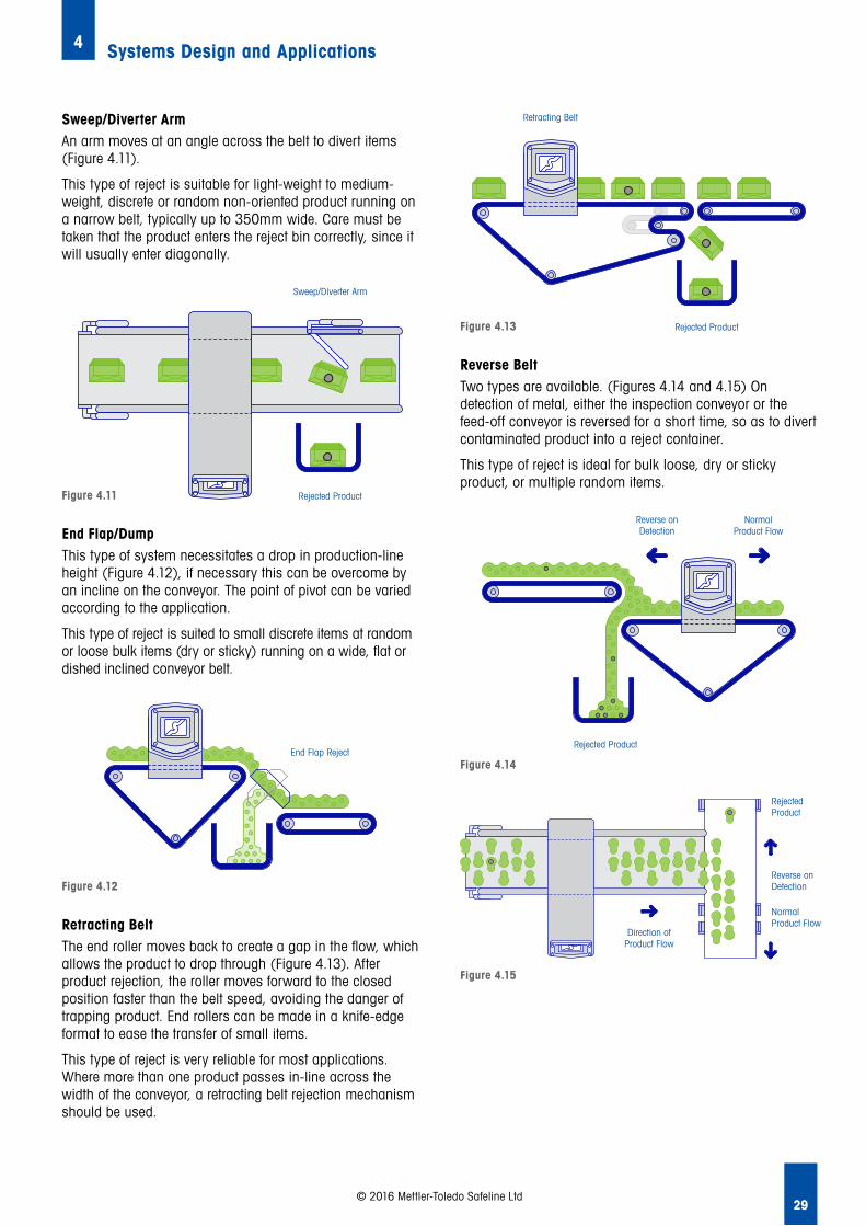
29
Systems Design and Applications4
© 2016 Mettler-Toledo Safeline Ltd
Retracting BeltThe end roller moves back to create a gap in the flow, which allows the product to drop through (Figure 4.13). After product rejection, the roller moves forward to the closed position faster than the belt speed, avoiding the danger of trapping product. End rollers can be made in a knife-edge format to ease the transfer of small items.
This type of reject is very reliable for most applications. Where more than one product passes in-line across the width of the conveyor, a retracting belt rejection mechanism should be used.
End Flap/DumpThis type of system necessitates a drop in production-line height (Figure 4.12), if necessary this can be overcome by an incline on the conveyor. The point of pivot can be varied according to the application.
This type of reject is suited to small discrete items at random or loose bulk items (dry or sticky) running on a wide, flat or dished inclined conveyor belt.
Sweep/Diverter ArmAn arm moves at an angle across the belt to divert items (Figure 4.11).
This type of reject is suitable for light-weight to medium-weight, discrete or random non-oriented product running on a narrow belt, typically up to 350mm wide. Care must be taken that the product enters the reject bin correctly, since it will usually enter diagonally.
Retracting Belt
Rejected ProductFigure 4.13 Rejected Product
Retracting Belt
Figure 4.12
End Flap RejectEnd Flap Reject
Sweep/Diverter Arm
Rejected ProductFigure 4.11 Rejected Product
Sweep/Diverter Arm
Reverse BeltTwo types are available. (Figures 4.14 and 4.15) On detection of metal, either the inspection conveyor or the feed-off conveyor is reversed for a short time, so as to divert contaminated product into a reject container.
This type of reject is ideal for bulk loose, dry or sticky product, or multiple random items.
Figure 4.15
Direction ofProduct Flow
RejectedProduct
Reverseon Detection
NormalProduct Flow
RejectedProduct
Direction of Product Flow
NormalProduct Flow
Reverse on Detection
Figure 4.14
Reverse onDetection
NormalProduct Flow
Rejected ProductRejected Product
NormalProduct Flow
Reverse on Detection

30
Systems Design and Applications4
© 2016 Mettler-Toledo Safeline Ltd
4.1.5 Stop Alarm SystemsA simple stop alarm system would probably only be considered acceptable by most manufacturers and major retailers under circumstances in which automatic rejection is not possible or practical. Typically, they are used on large bags or boxes where rejection is difficult.
When metal is detected, the conveyor should stop immediately and all products on the conveyor belt should be removed for investigation. The system should also be fitted with an audible and/or visual alarm. It should only be possible to re-start the system using a key held by a nominated person or have a controlled reset as an option.
These solutions are generally considered high-risk, and depend entirely on the competence of the line operator.
4.1.6 Metallised Film ApplicationsTo achieve good detection of metal in a metallised film pack, it is necessary to remove the signal generated by the fine aluminium coating present on the plastic film as discussed in section 18.2.6.
It is preferable to have a space between the product and the aperture of approximately 50 to 60mm all around; and extremely high levels of sensitivity can be achieved.
4.1.7 Aluminium Foil ApplicationsWhen the packaging material includes aluminium foil, it is possible to undertake metal contamination checks before packing, using a balanced coil-type metal detection system. Alternatively, a ‘Ferrous-in-Foil’ type detector can be used after packing. However, as stainless steel and non-ferrous metals are not detectable using the ‘Ferrous-in-Foil’ unit, this is only recommended when no other alternative is available.
4.1.8 Reject TimingA time-gap is usually required between the moment of detection and the moment of rejection, so as to allow the metal contamination to move to the reject point.
This time-gap can be just fractions of a second on high-speed applications, where the detector and reject device are close together; by contrast, the time-gap can be as much as 30 seconds, when rejection is planned (manually or automatically) at some remote point.
A second independent timer is also required in order to control the length of time during which the reject device operates. This is usually adjustable from approximately 0.5 seconds to 10 seconds. A punch-type reject would require the shortest time, whilst a retracting band system would normally operate for several seconds to remove larger items from a slow-moving belt. Both timers are normally available as standard features from the detector system manufacturer.
It is important that the timers are capable of being re-set immediately, and that the detector is still operational while timing-out. The detector must also be capable of detecting a second particle in a following pack; then it must either re-set or extend the timer to ensure that the second pack is also rejected. A continuous stream of metal particles should result in the reject device operating continuously until all the metal contaminated products are removed.
Variable Speed/Stop-Start ApplicationsAccurate rejection and timing become more complex if the transport conveyor has variable speeds or can be stopped when product is located between the detector and the reject system. The time taken for the product to move to the reject position is not constant and so a simple time-delay method cannot be used.
The normal solution is to use a speed encoder which can monitor both belt movement and the position of product on the belt. A shift register is a device which will give an output signal after it has received a pre-determined number of input pulses. It does not matter if these pulses are received rapidly or are received in a spaced-out pattern over a long period.
The input pulses are produced by an encoder fitted to the shaft of a roller on the conveyor system. The pulse-generator is normally made from a metal disc with teeth or holes cut into it. Each time a tooth on the disc obscures the photo-electric device or passes close to the proximity sensor, a pulse is generated. In the example shown (Figure 4.16), each revolution of the disc generates fifteen pulses.
Figure 4.16
Proximity Sensor
Pulse Generator
Proximity Sensor
Pulse Generator
A higher number of teeth will produce more pulses per revolution, which will ultimately allow more accurate registration of the product.
The signals from multiple or consecutive metal particles will be stored in the shift register and sequenced through, ensuring that each one is subsequently rejected.
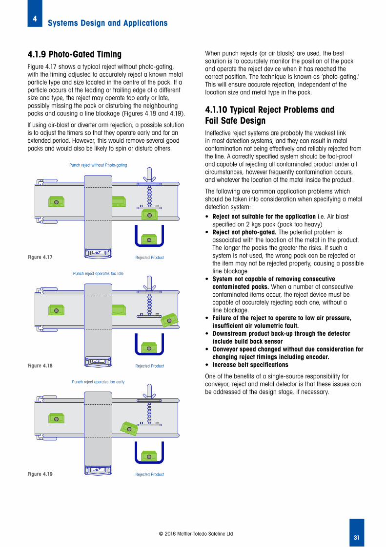
31
Systems Design and Applications4
© 2016 Mettler-Toledo Safeline Ltd
4.1.9 Photo-Gated TimingFigure 4.17 shows a typical reject without photo-gating, with the timing adjusted to accurately reject a known metal particle type and size located in the centre of the pack. If a particle occurs at the leading or trailing edge of a different size and type, the reject may operate too early or late, possibly missing the pack or disturbing the neighbouring packs and causing a line blockage (Figures 4.18 and 4.19).
If using air-blast or diverter arm rejection, a possible solution is to adjust the timers so that they operate early and for an extended period. However, this would remove several good packs and would also be likely to spin or disturb others.
When punch rejects (or air blasts) are used, the best solution is to accurately monitor the position of the pack and operate the reject device when it has reached the correct position. The technique is known as ‘photo-gating.’ This will ensure accurate rejection, independent of the location size and metal type in the pack.
4.1.10 Typical Reject Problems and Fail Safe DesignIneffective reject systems are probably the weakest link in most detection systems, and they can result in metal contamination not being effectively and reliably rejected from the line. A correctly specified system should be fool-proof and capable of rejecting all contaminated product under all circumstances, however frequently contamination occurs, and whatever the location of the metal inside the product.
The following are common application problems which should be taken into consideration when specifying a metal detection system:• Reject not suitable for the application i.e. Air blast
specified on 2 kgs pack (pack too heavy)• Reject not photo-gated. The potential problem is
associated with the location of the metal in the product. The longer the packs the greater the risks. If such a system is not used, the wrong pack can be rejected or the item may not be rejected properly, causing a possible line blockage.
• System not capable of removing consecutive contaminated packs. When a number of consecutive contaminated items occur, the reject device must be capable of accurately rejecting each one, without a line blockage.
• Failure of the reject to operate to low air pressure, insufficient air volumetric fault.
• Downstream product back-up through the detector include build back sensor
• Conveyor speed changed without due consideration for changing reject timings including encoder.
• Increase belt specifications
One of the benefits of a single-source responsibility for conveyor, reject and metal detector is that these issues can be addressed at the design stage, if necessary.
unch reject operates too early
Rejected ProductFigure 4.19
Punch reject operates too early
Rejected Product
Punch reject operates too late
Rejected ProductFigure 4.18
Punch reject operates too late
Rejected Product
Punch reject without Photo-gating
Rejected ProductFigure 4.17
Punch reject without Photo-gating
Rejected Product

32
Systems Design and Applications4
© 2016 Mettler-Toledo Safeline Ltd
4.2 Satisfying Retailer and Food Industry RequirementsThe metal detection system design can include simple additional control devices that will ensure a reject device is operating properly, that contaminated packs are accurately rejected − and that the metal detection system is operating in a fail safe mode. Implementation of the following design requirements generally represents good practice, and will probably satisfy most brand retailer and food industry requirements:• An automatic reject system to effectively remove product
from the production line• A lockable reject bin (with optional bin door lock monitor)
which receives rejected product. Only authorised, trained personnel should have access to the reject bin. This helps to avoid the risk that if product is rejected into an open container and is readily accessible, it can easily be returned to production in error.
• A warning device to indicate when the reject bin is full of product
• A full enclosure between the detector head and reject bin• An audible and visual indication of system status e.g.
detect head fault, reset fault etc.• A photocell to detect each pack passing through the
system (to facilitate the correct timing of the reject mechanism, irrespective of the position of the metal within the pack)
• An automatic belt-stop fail safe system in response to the certain events:
− Reject bin full − Loss in air pressure − Reject confirmation system fault etc.• A reject confirmation error highlighting when products are
not correctly rejected.• Reject check sensor to confirm operation of the photo
gating system• Drive roller shaft encoder to manage variable speed and
stop / start systems.• Build back sensor to prevent products backing up though
the Metal Detection system
It should only be possible to re-start the system via a security password or a key held by a nominated person. Suitable procedures should be in place with respect to any products in the event of metal detector conveyor stopping for and reason, all products should be removed and subsequently re-inspected.
4.3 Inspection of Liquids, Slurries and Pastes in a Pipeline Inspection of pumped liquids, slurries and pastes can be achieved by replacing a short section of metal the transport pipe with a food-grade non-metallic pipe, and then passing it through a metal detector (Figure 4.20). The choice of the pipe will be influenced by:• The style of the pipe connection required• Product type and viscosity• Nature of the product• The product temperature• The pipe pressure expected
Care should be taken to design the installation so that the pipe will not be under strain from the weight of the in-coming and out-going stainless steel transport pipes.
When metal contamination is detected, a sanitary three-way valve can operate to divert the contamination. Alternatively, the pump can be stopped and the contamination flushed out manually. The choice of the valve will be influenced by product type (inclusion of product solids) temperature and viscosity.
Some valves are best suited to low-viscosity products such as juices etc. If the pipe-cleaning procedure includes a cleaning plug being flushed down the pipe, (sometimes referred to as a ‘pig’), the selected valve must be of a ‘straight-through’ non-restrictive design.
Typical products suitable for pipeline inspection include liquid chocolate, ice cream, soup and meat slurry.
This type of application should be considered where the extra-sensitivity capability of a relatively small aperture outweighs the benefit of final package inspection. This is especially true if the final packing material contains metal (as in a canning line).
Pumped product is seldom totally homogeneous. Voids and bubbles frequently occur.
Under normal conditions, product passes through the detector coils and any product effect tends to cancel out signals, and the detector can be adjusted to give high-sensitivity readings. (Figure 4.20) If, however, a void or bubble appears as it passes through the first coil (Figure 4.21), the detector will sense a large product difference and a false reject may occur with conventional balanced coil metal detectors.
Product Flow Accept
RejectFigure 4.20
A full pipe tends to cancel out product signals

33
Systems Design and Applications4
© 2016 Mettler-Toledo Safeline Ltd
With the development of MSF technology and Product Signal Suppression this effect is reduced and the instance of false rejects is virtually eliminated.
The product speed in the pipe will ultimately determine the position of the reject valve relative to the metal detector. Since the valve has a minimum divert response time, the distance between the valve and the detector must be increased, directly proportional to the product speed and the valve response time.
For product likely to solidify if pumping stops, such as liquid chocolate, the throughput pipe can incorporate a hot-water-jacket heating system; this is because electrical heating wires cannot be passed through a detector.
4.3.1 Fail Safe Design for Pipeline SystemsThe following system design features are generally considered good practice, and will probably satisfy most brand retailer and food industry requirements:• A reject mechanism which can isolate a plug of product
which may contain metal contamination• Rejection of the contaminated product to a suitable
secure container• An audible and visual indication to show that product
has been rejected• A reject confirmation system that will stop the flow of
product if there is a failure of the reject system. It should only be possible to re-start the system via security password or a key held by a nominated person.
4.3.2 Testing ConsiderationsTesting access and recovery should be built into the system, so that testing of the detector and reject device can be performed quickly and reliably. If possible a test sample access port to allow the introduction of a test sample upstream of the metal detector.
The location and design of the access port should allow the sample to travel at normal speed through the metal detection system. There should also be some means of catching the test sample, via a catch grid or open catch valve, if it is not detected.
A Full Pipe Tends to Cancel Out Product Signals
Figure 4.21
4.4 Gravity Feed Inspection of Bulk Powders and Free-Flowing SolidsAny free-flowing powder or granular product (such as flour, peanuts, rice, plastic pellets, milk powder, ingredients and cocoa beans) can be inspected under free-fall conditions using a gravity-fed free-fall detector and a high-speed diverter system (Figure 4.23).
Under normal operational conditions, the product falls under gravity and with the relatively high volumes that can pass through a small detector aperture delivering, very high sensitivity can be achieved.
The detector and auto-reject should be mounted on a rigid framework with sufficient space between them to ensure that metal contamination is always rejected. Consideration should be given to the design of the reject mechanism with regard to the potential for product leakage through the reject position.
In certain applications (such as fine powder), there can be an accumulation of product dust in the reject device that can potentially leak out of the reject position, resulting in unacceptable product waste. In such applications, a sealed reject type is recommended.
Product flow should be continuous free-fall or batch free-fall. Systems of this type are not considered suitable where product is likely to back up in the throughput pipe and move slowly.
The system should have a fixed speed of response, whatever the frequency of operation. The system should also be capable of moving to the reject position more quickly than the time taken for a metal particle to fall from the detector to the reject device.
Frequently, the overall system height is a limitation to the use of gravity-feed systems, particularly where little headroom exists.
The following limiting variables have a direct relationship on the overall system height.
Rejected ProductGood Product
Dry Product Flow
Figure 4.23
Good Product Rejected Product
Dry Product Flow
Catch grid valve at end of product flow acts as fail safe should the test piece fail to be rejected
Figure 4.22

34
Systems Design and Applications4
© 2016 Mettler-Toledo Safeline Ltd
4.4.1 Initial Fall Height of the ProductThe fall-height of the detector is normally expressed from the point at which the product begins to fall to the top of the detector flange. This height will determine the product’s velocity at the point of inspection. Ideally, the fall height should be reduced to a minimum by locating the equipment as close as possible to the point of initial fall, without infringement of the ‘metal-free zone’ (see Section 1.4.4).
By way of general guidance, the maximum fall-height for a 150mm diameter-aperture detector would be approximately 800mm; however, this may vary depending upon the actual detector specification. As the fall-height is increased, the distance between the detector and the reject valve must also be increased in order to maintain adequate time for the valve to respond.
4.4.2 Detector ApertureThe size of the aperture will determine the operating sensitivity of the system (subject to the frequency of operation). The maximum thru put of the system and the minimum overall system height. Special technology (such as Zero Metal-Free Zone technology) will keep this distance to a minimum. The aperture size will also determine the distance that the reject diverter must travel in order to reject product.
4.4.3 System Response TimeThis covers the speed of response of the relay or solid-state output, air solenoid or air cylinder. It also covers the time taken to move the reject diverter to the reject position.
4.4.4 Reject AngleThe reject angle must not be so large that it creates a blockage or bridges the product. As the length of the reject flap is reduced, the reject angle increases. An angle of between 25º to 30º is considered a maximum for most products.
4.4.5 Reject DesignThe speed of response can be slowed by factors such as product build-up on the reject device, a drop in air pressure and ageing of bearings. A sufficient safety margin is needed in the design to ensure that metal is rejected with 100% accuracy.
4.4.6 Fail Safe Design for Gravity-Fall SystemsThe following system design features are generally considered good practice, and will probably satisfy most brand retailer and food industry requirements:• A reject mechanism which can isolate the actual product
which may contain metal contamination• An audible and visual indication of system status e.g.
product has been rejected• A reject confirmation system that will stop the flow of
product if there is a failure of the reject mechanism. It should only be possible to re-start the system via a secure password or a key held by a nominated person. However in some cases a controlled push button reset may be the more standard practice.
• Fail safe design i.e. Fail to safety on power outage• An audible and visual indication of system status e.g.
product has been rejected
4.4.7 Static ConsiderationsFalling dry powders and granules can generate static electricity. The build-up of large static charges could have a detrimental effect on the performance of the metal detection system or even pose a safety hazard. Some products will be more prone than others, and environmental conditions (such as humidity) will be a contributing factor. In order to prevent the build-up of large static charges, the following measures should be considered:• All metal near the metal detection system (pipes, flanges,
supports) should be properly grounded• Plastic throughput tubes should be made from food-
approved conductive plastic (e.g. FDA approved), which should be grounded.
• The system should have a single-point earth
4.4.8 Testing ConsiderationsTesting access and test sample recovery should be built into the system so that testing of the detector and reject device can be performed quickly and reliably. There should be a test access port to allow the introduction of a test sample at the point at which the product begins to fall, so that the test sample speed will be the same as the product.
A safety catch grid should be inserted into the normal product flow below the valve accept position, so that the test sample can be safely recovered if it is not detected – or if the valve fails to operate.
The test grid should be capable of being inserted quickly during test and removed from the product flow afterwards. The use of a test grid on the reject side of the valve is recommended; this helps to ease the recovery of the test sample when it is rejected.

35
Systems Design and Applications4
© 2016 Mettler-Toledo Safeline Ltd
4.5 Vertical Packaging ApplicationsInstalling a metal detector directly onto, or into, a packaging or process machine, can have a number of advantages for both the user and the supplier of the original machinery. i.e. • Cost reduction, • Sensitivity performance increase• Overcomes the limitations of metallic packaging• No moving parts that wear
Where installation is required in a restricted space, special technology (such as Zero Metal-Free Zone technology) can be used. This allows metal structures and components to be positioned very close to the detector without interference.
4.5.2 Vertical Form Fill Seal
A Zero Metal-Free Zone detector can be fitted between a scale e.g. a multi-head weigher and a vertical form-fill seal bag-maker (Figure 4.24). Often, a large detector, e.g. 175mm / 200mm (7” / 8”) is required, which would demand a larger metal-free zone making installation difficult or often impossible due to the space needed.
4.5.3 Rejection and Fail Safe Design for Vertical Packaging Applications
The following system design features are generally considered good practice, and will probably satisfy most brand retailer and food industry requirements:• A reject mechanism which can isolate the actual
product which may contain metal contamination. If a reject mechanism is not practicable, the packaging machine should have the capability of forming a double pack and stop.
• An audible and visual indication to show that the packaging machine has stopped.
• A reject confirmation system that will stop the flow of product if there is a failure of the reject mechanism or failure of the bag maker to stop. It should only be possible to re-start the system via a security password or a key held by a nominated person. However under controlled conditions a push button reset could be the adopted practice.
Figure 4.24
PlasticFlangedFunnel
PlasticThroughputTube
V.F.F.S. Bagmaker
DetectorHead ‘ZMFZ’
Scale DischargeChute
Aperture size Ferrous Metal
Non Ferrous Metal (brass, copper and aluminium).
Stainless Steel 316 grade non-magnetic
150 mm 0.6 to 0.8 mm 0.8 to 1.0 mm 1.0 to 1.2 mm
200 mm 0.8 to 1.0 mm 1.0 to 1.2 mm 1.2 to 1.5 mm
250 mm 1.2 to 1.5 mm 1.5 to 1.8 mm 1.8 to 2.0 mm
Table 4a: Typical Sensitivity Ranges in Vertical Packaging Applications
Patented Zero Metal-Free Zone technology allows high sensitivity levels to be maintained (without false rejects) in a minimum space, making installation easier and avoiding the danger of product breakage.

36
5
5 Metal Detection, X-ray Inspection or Both Technologies?
5.1 The Capabilities of Metal Detection and X-ray Inspection Systems
5.2 Product Effects
5.3 Packaging Effects
5.4 Which Technology - Metal Detection, X-ray Inspection or Both?
Metal Detection, X-ray Inspection or Both Technologies?
The quality and safety of food and pharmaceutical products depends on the due diligence exercised during the production process, in order to exclude contaminants from finished products.
© 2016 Mettler-Toledo Safeline Ltd
Food manufacturers must comply with regulations and standards to prevent contamination, such as the Food Safety Modernization Act (FSMA), Global Food Safety Initiative (GFSI), the British Retail Consortium (BRC), Food Safety System Certification 22000 (FSSC22000) and International Feature Standard for Food (IFS).
Pharmaceutical manufacturers have their own compliance requirements. The choice of protection and inspection equipment hugely affects product quality, product safety and consumer confidence. Manufacturers must decide whether to install a metal detection system, an x-ray inspection system, or both – and this chapter compares the two.
5.1 The Capabilities of Metal Detection and X-ray Inspection Systems Metal detection and x-ray inspection systems can be installed at Critical Control Points (CCP) to inspect in-coming raw materials prior to processing – or at numerous other points in the manufacturing process. Inspection systems can also be installed at the end of the production or packing line.
As discussed in Chapter 1 modern metal detectors can identify all metals, including ferrous (chrome, steel, etc.), non-ferrous (brass, aluminium, etc.), as well as both magnetic and non-magnetic stainless steels in food and pharmaceutical products.
Metal detection and x-ray inspection systems can be used to inspect unpackaged or packaged products, including tall rigid containers such as glass jars, bottles and plastic containers. X-ray technology is commonly used to inspect metal cans and products packed in aluminium foil. However, the latest metal detection technology (See Chapter 3 detailing Multi Simultaneous Frequency technology) now makes it possible to inspect products packaged in metallised film and achieve similar detection levels to that of an x-ray system.
Both metal detection and x-ray inspection systems can be used to inspect liquids, pastes and slurries in pipeline applications.

37© 2016 Mettler-Toledo Safeline Ltd
For the inspection of gravity-fed, free-falling products, metal detection is the only choice. Gravity-fed, powdered or granular products don’t travel at the same speed; they accelerate as they fall, plus the direction of travel is not uniform, since they bounce off each other. X-ray inspection systems can’t offer a satisfactory solution when handling this type of product. As the product tends to be dry and non-conductive the sensitivity levels achieved with using a metal detection system are extremely high.
5.2 Product Effects The effect of the products being tested will depend upon the chosen inspection technology; both metal detectors and x-ray systems have differing inspection capabilities which directly impact sensitivity.
Historically products with high moisture content have been more of a challenge for a metal detector to detect the smallest contaminants as the signal given off from the product, known as the product effect has masked the signal given off by the metal contamination, however now with development of Multi Simultaneous Frequency (MSF) technology this effect is considerably reduced and in many cases what was previously considered a challenging product is now considered a relatively easy product for a metal detector to inspect with the result being a vastly improved level of achievable sensitivity.
X-ray inspection technology can also be impacted by certain characteristics of the products being inspected. The ease with which contaminants can be identified by x-ray inspection depends on various factors such as product density, product depth and product homogeneity. For example, when using an x-ray system if the product includes free salt crystals such as dry crackers and biscuits these salt crystals due to their density can limit the performance achieved by the X ray system when compared to the same product that doesn’t include free salt crystals. Also products with varying texture can affect how the X ray performs; the more homogeneous the product the better the overall sensitivity.
5.3 Packaging EffectsThe packaging material used can impact upon detection levels to a differing degree, depending upon the inspection technology used.
A vast array of packaging materials is currently used in the food and pharmaceutical industries:• Plastic trays or overwrap• Paper• Metallised film • Aluminium foil • Glass• Metal cans• Ceramic pots• Doypacks• Composite cartons/ tubes
An application area in which x-ray inspection excels, over traditional metal detection technologies, is when inspecting products packed in aluminium foil. Due to the way in which the x-ray system works, this type of packaging material has a negligible impact on detection levels.
5.3.1 Metallised Film Packaging Products packed in metallised film packaging have historically been inspected by metal detectors using low-frequency techniques (depending on the film thickness). However, as mentioned in section 5.2, new technology is now available from some metal detection companies enabling the sensitivities achieved with a metal detector to be very similar to that achieved when using an x-ray system and in some cases the detection capability of the metal detector can be greater.
In some cases however, if the application allows it is preferable to inspect these products prior to packing by using a “throat” type metal detector, a good example of this is seen in the snack food sector where throat metal detectors are seen as the solution of choice due to the high sensitivity levels achieved and the relatively low cost of investment and ownership.
5.3.2 Aluminium Foil Packaging Aluminium packaging, such as foil wraps and product trays, are a bigger challenge for metal detectors. Detectors using balanced coil technology are unable to inspect products in aluminium packaging – so a different technology, known as ’ferrous-in-foil’ detection, must be used. The drawback here is that this technology can only detect magnetic metals and may not be an acceptable solution. This is a good example where the choice for using x-ray is clear.
An application area in which x-ray inspection excels, over traditional metal detection technologies, is when inspecting products packed in aluminium foil. Due to the way in which the x-ray system works this packaging material has a negligible impact on detection levels.
5.3.3 Aluminium Contaminants in Non-Metal Packaging Aluminium is a lightweight metal and a good electrical conductor. Since its density is lower compared to other metals such as ferrous and stainless steel this causes a reduction in the sensitivity on an x-ray inspection system. In these cases, aluminium is detected at twice the size of ferrous or stainless steel. In contrast, due to its excellent conduction properties, aluminium can often be detected at smaller sizes using metal detection technology so metal detection is generally the better solution.

38
Metal Detection, X-ray Inspection or Both Technologies? 5
© 2016 Mettler-Toledo Safeline Ltd
5.3.4 Metal Contaminants in Non-Metal Packaging For cost-effectiveness, metal detectors are the best solution when looking for metal contaminants only once all the factors above have been taken into consideration. However, if the requirement is to detect metal contaminants and non-metallic foreign bodies, x-ray systems are the appropriate solution. If there are any doubts a product test would always be advisable.
5.3.5 Non-Metal Contaminants in Any PackagingX-ray inspection is the only solution, and has the ability to detect non-metallic contaminants such as glass, mineral stone, calcified bone, and high-density rubber and plastic.
5.3.6 Product Size Limitations Both x-ray and metal detectors can be designed to accommodate any product size. For larger packs and products, the aperture height or opening must be increased and, as a general rule, the larger the aperture height and product, the lower the sensitivity.
5.4 Which Technology – Metal Detection, X-ray Inspection or Both? Metal detection and x-ray inspection offer different capabilities – and in order to assess those capabilities fully, the first step is to carry out a Hazard Analysis and Critical Control Points (HACCP) audit. This will help to understand the requirements of any customer or compliance-related issues driven by the GFSI and/or major retail groups.
A HACCP audit will identify the risks of contamination being introduced into the manufacturing process, and the types of contamination likely to be encountered. CCPs should be established to mitigate the risks, and product inspection equipment needs to be installed at these points to reduce the risk of contamination to acceptable levels.
If the HACCP audit determines that metal is the only likely contaminant to be found, then a metal detector is the best solution. Likewise, if other contaminants like glass, mineral stone, calcified bone or high-density plastics and rubber are identified as likely to be encountered, then x-ray is a more suitable solution. Recalling the packaging and product effects mentioned previously, it would be advisable to conduct product testing to establish the most appropriate technology.
In many cases, there’s only one suitable solution – either metal detection or x-ray inspection. However, there are also occasions when it could be necessary to install both metal detection and x-ray inspection at different CCPs on the same production line.
HACCP and its principles are explained in the Chapter 9 Selecting Control Points).
5.4.1 Installation and Testing Requirements Metal detection and x-ray inspection systems can be supplied with a variety of product-handling devices, including an array of fully-automatic reject devices. Both metal detection and x-ray inspection systems also require regular performance test checks to be carried out at prescribed intervals. Installation, commissioning and training is explained in more detail in Chapters 11 and 12. However, recent advances in metal detection technology such as the development of Predictive Analytics, makes it possible to extend the interval between scheduled tests of the metal detector. This in turn can make it very attractive to the user as it gives potential for an increase in the user’s OEE percentage.
5.4.3 Fast/Variable Line SpeedsMetal-detection and x-ray inspection systems are both suitable for variable and fast production lines. Metal detectors will detect contaminants in products moving at low and high speeds, including conveyors running at speeds above 400m/min (although very few conveyorised processes run at such high speeds).
X-ray inspection systems can monitor conveyor lines running at up to 120m/min. Even higher inspection volumes/ speeds can be achieved in pumped and bulk applications for both metal detection and x-ray technology. The choice of technology is dependent on multiple factors such as types of contaminant, product type and packaging material; speed generally isn’t a deciding factor.
5.4.4 Limited SpaceA metal detection Detector Head takes up less space than an x-ray inspection unit, so in situations where installation space is limited and metal is the likely contaminant, a metal detector may be the best solution. If packed products are being inspected, both systems will normally need a conveyor system and an automated reject system. In some situations, the differences in overall system length can be very small. Some metal detector companies offer what is referred to as Zero Metal Free Zone (ZMFZ) technology. This allows the overall size of the metal detection system to be drastically reduced and it is common place to find metal detection systems that take up less than 1000mm of line space.
39
Metal Detection, X-ray Inspection or Both Technologies? 5
© 2016 Mettler-Toledo Safeline Ltd
5.4.5 Industry Standards and Codes of PracticeRecent changes in food and pharmaceutical industry safety standards are resulting in the increased adoption of metal detection and x-ray inspection systems by manufacturers. A growing number of major retailers are setting their own codes of practice, which contain specific advice regarding product inspection equipment based on the Global Food Safety Initiative (GFSI), the British Retail Consortium (BRC), Food Safety System Certification 22000 (FSSC22000) and International Featured Standard for Food (IFS). In addition, pharmaceutical manufacturers have their own compliance requirements.
5.4.6 Simplifying the ChoiceFollowing the development of both metal detection and x-ray inspection technologies the choices are no longer made by simply choosing one or the other. This chapter is a good starting point for choosing an appropriate technology, but it can’t provide all the answers. There’s often an area of indecision that requires further levels of discussion with product inspection experts.
If cost is the sole criterion for deciding, metal detection is a more suitable solution. However, product safety decisions are rarely that simple. The performance of each solution is affected by the size of the product to be inspected, plus it’s important to compare lifetime costs, not just the upfront capital costs.
The type of product and the likely contaminants will also affect the choice; consideration must be given to the HACCP audit and CCPs on the production line. Sometimes, the answer is to install more than one detection system at different CCPs on the same production line.
For example, a metal detector or a bulk flow x-ray inspection system placed early in the processing line can remove large metal or non-metallic contaminants before they reach delicate machinery downstream, where they could damage the machine or become fragmented into multiple, smaller, more difficult to detect contaminants.
An x-ray inspection system can be installed at the end of the line to detect a wider range of contaminants and to carry out other quality checks, such as confirming pack integrity and checking the contents of the pack before the product leaves the factory.
There is an area of overlap between the two technologies where you could choose either one. Then it’s not so much a question of which technology is better, but which technology is most appropriate for your particular application and budget.

40
Metal Detection, X-ray Inspection or Both Technologies? 5
© 2016 Mettler-Toledo Safeline Ltd
5.4.7 Summary TableThe following table summarises the key differences between the two technologies:
Metal Detection X-ray Inspection
Product formats Packaged, conveyorised products, loose, bulk products, free-falling and vertically-packed products (including powders and granular products), pumped liquids, pastes and slurries, continuous web products
Packaged, conveyorised products, loose, bulk products, pumped liquids, pastes and slurries, continuous web products
Contamination detection Detection of all metal contaminants, including ferrous, non-ferrous (including aluminium) and magnetic and non-magnetic stainless steels
Detection of dense contaminants like ferrous, non ferrous and stainless-steel, as well as other contaminants like glass, stone, bone, high-density plastics and some rubber compounds
Detectable contaminants Contaminants must be austenitic (magnetisable) or electrically conductive
Contaminants must be high-density or have a high atomic mass number
Aluminium contaminants Easily detected Detectable, but not as easily detected as other metals
Quality checks Detection of metal contaminants Detection of dense contaminants and simultaneous quality checks for mass measurement, seal inspection, fill-level control, component count,detection of missing and broken products, as well as packaging
Product texture No effects May limit performance
Conductive product Can be inspected Can be inspected
Metallised film-packed products Can be inspected Can be inspected
Aluminium foil-packed products Cannot be inspected effectively Can be inspected
Pack size effects The larger the pack, the less sensitive The larger the pack, the less sensitive
Increased aperture size Sensitivity can decline, and costs increase moderately
Sensitivity can decline, and costs increase significantly
Short Conveyor length Short conveyor lengths or space required for insertion
Short conveyor length may need special guarding for radiation safety
High line speeds Operates at high line speeds Operates at high line speeds
Variable line speeds Operates at variable line speeds Operates at variable line speeds
Gravity Fed Production Can be inspected Cannot be inspected
Table 5a

41
Metal Detection, X-ray Inspection or Both Technologies? 5
© 2016 Mettler-Toledo Safeline Ltd
Notes

42
6
6 Reasons for a Metal Detection Programme
6.1 Minimising Metal Contamination
6.2 Minimising Costs
6.3 Protection of the Customer and Consumer
6.4 Protection of Brand and Reputation
6.5 Certification
6.6 Employee Buy-In
6.7 Due Diligence and Regulatory Compliance
6.8 Retailer and Consumer Brand Codes
6.9 References
© 2016 Mettler-Toledo Safeline Ltd
Reasons for a Metal Detection Programme
For many companies, the purchase of a metal detection system can represent a significant capital investment, so it is important that the equipment is reliable, appropriately designed for the intended application – and used in the most effective way. Adherence to these principles will ensure that the metal detection system generates a good Return On Investment (ROI) by minimising costs and maximising product safety.
The most effective use of a metal detection system is as part of a wider-reaching metal contaminant reduction programme designed to achieve several aims:1. To detect contamination in product, and…2. To carry out appropriate preventive actions when
contamination is detected, and… 3. To take appropriate measures which prevent metal
contamination occurring in the first place
The justification for purchasing a well-designed metal detection system (and the reasons for its implementation) can be demonstrated by considering the following benefits, which are discussed in detail in this chapter:• Minimising metal contamination• Minimising costs• Protection of the customer and consumer• Protection of brand and reputation• Certification• Employee buy-in• Due diligence and regulatory compliance• Conforming with retailer and consumer brand codes

43© 2016 Mettler-Toledo Safeline Ltd
6.1 Minimising Metal ContaminationMetal contamination can still be a cause of consumer complaints, even when metal detection systems are used. However, such complaints are not normally due to the metal detection system failing; they are usually associated with lack of effective controls, poor working methods, incorrect system specification and incorrect design.
Many incidences of metal contamination do not result from the presence of tiny metal pieces but from the presence of much larger items such as washers, bolts, and pieces of blades or screens. These kinds of items should be detectable by even the most basic type of detector.
A well designed metal detection programme should be able to address these wider-ranging issues − although the programme should also focus on how to minimise instances of contamination in the first place.
Contamination prevention can be achieved through factors such as:• Good manufacturing practice• Prerequisite programmes• Selection of the correct equipment and the use of certified
test samples• Effective testing• Gaining a greater understanding of how industry
standards, customer requirements and legislation impact on manufacturers
6.2 Minimising CostsThe costs associated with implementing and maintaining an effective metal detection programme are significantly lower than the potential costs of failure to do so.
A metal-contaminated product found before shipment will inevitably result in costly product and packing wastage, possible machinery damage, and loss of output. Whilst costs can easily be allocated to such events, they can be particularly high when there is loss of output − particularly on high-volume automated production lines.
However, even these costs can be overshadowed by instances of contamination discovered after shipment; these can result in loss of customer satisfaction, product recall, adverse publicity, and potential legal action.
Time and money spent reducing the incidence of metal contamination in the first place will result in less internal waste, reduced loss of output and fewer complaints. This will yield a better return than money spent responding to contamination after it has occurred, and dealing with its many costly consequences.
As well as leading to reduced incidence of contamination and reduced failure costs, a correctly implemented metal detection programme will undoubtedly lead to improved customer and consumer satisfaction, as well as greater profitability and better protection of the manufacturer’s brand.
6.3 Protection of the Customer and ConsumerAlthough modern manufacturing techniques constantly strive to eliminate the occurrence of metal contamination in products, there will always be occasions where processes or procedures break down, resulting in its occurrence.
Manufacturers and their employees have an obligation to customers and end consumers to minimise instances of contamination; they are also obliged to ensure consistent quality is maintained and that all possible steps are taken to protect the welfare of the end user.
Failure to achieve these aims can create potential animosity between manufacturer, retailer and customer; they can also result in the potential breakdown of the customer relationship, as well as the loss of future business opportunities.
6.4 Protection of Brand and ReputationPowerful product branding gives customers a perceived assurance of safety and quality. Effective, visible and memorable branding is frequently responsible for driving consumer repeat purchases − and so is an important tool in maximising sales and justifying premium product pricing charged by manufacturers and retailers.
For this reason, an organisation’s responsibility is not only related to protection of the end user, but also to the brand and to the on-going reputation of the company. Product brands are important assets that need to be managed carefully, and must be protected, at all costs, from adverse publicity.
Contaminated product found by consumers can have a serious negative impact on any organisation, resulting in damage to the brand and potentially costly recalls. In the event of a company being investigated as a result of a customer complaint, documentation will provide invaluable evidence of the correct operation of the metal detection programme.
6.5 CertificationIt is highly likely that metal detection systems will be the focal point of any customer/retailer audit because of their contribution to the safety of the manufacturing process. In addition, the presence of metal detection systems provides evidence of good manufacturing and product safety practice. Such evidence will undoubtedly be requested (if not immediately, at some time in the future) by any one of a number of audit processes, such as:• Internal food safety and management system audits• Customer audits• Quality management system audits e.g. ISO9001:2000• Food safety management system audits e.g.
ISO22000:2005, SQF1000/2000 Code• Regulatory audits e.g. FDA, USDA, International Food
Standard (IFS), British Retail Consortium (BRC)

44
Reasons for a Metal Detection Programme6
© 2016 Mettler-Toledo Safeline Ltd
6.6 Employee Buy-InFormalised procedures and working practices relating to product safety and brand protection will help support overall quality throughout the manufacturing organisation. These procedure and working practices can be reinforced by key customer training sessions and awareness seminars. Such training can be organised and run by the metal detector manufacturer or appointed representative.
6.7 Due Diligence and Regulatory ComplianceCurrently, there is no broad-based legal requirement which forces manufacturers to install metal detection equipment or implement a metal detection programme. However, where proceedings result from the presence of metal contamination in a food or pharmaceutical product, manufacturers could be called upon to prove that they have exercised due diligence in their processes; failure to do so could result in serious consequences.
Due diligence is easier to prove when an organisation has a documented system which continually assesses the risks to food safety and allocates resources to minimise these risks.
In the absence of any definitive metal detection legislation, several regulatory bodies have emerged with standards and codes of practice to which manufacturers can adhere. These codes advocate universal inspection of all food and allied products by metal detection equipment. A few examples are shown below.‘Every company needs to perform a hazard analysis for every product it produces to assess the risk of metal contamination in their products. If the hazard analysis shows there is risk of metal contamination, then a metal detector will be required.’BRC Global Standard Guidelines
‘Effective measures shall be taken to protect against the inclusion of metal or other extraneous material in food. Compliance with this requirement may be accomplished by using sieves, traps, electronic metal detectors, or other suitable effective means.’ Food and Drug Administration (FDA)GMP: 21CFR 110.80(b)(8)
Some of these standards are beginning to play a part in supplier selection and the specification of metal detection standards for manufacturers. They generally require control in the form of a documented programme covering protective and safety-related actions.
6.8 Retailer and Consumer Brand CodesMajor retailers, and custodians of leading consumer brands, have also played a major part in developing their own codes of practice – and these need to be adhered to in order to satisfy supply agreements. Such standards can vary considerably across geographical territories – and, increasingly, the implementation of a formal metal detection programme is expected before supplier approval is granted.
6.9 References Links to various sources and types of information are included below for reference:
ANVISA − Brazilian Health Surveillance Agencyhttp://www.portal.anvisa.gov.br/wps/portal/anvisa-ingles
British Retail Consortium (BRC)http://www.brc.org.uk
Codex Alimentariushttp://www.codexalimentarius.net
European Food Safety Authority (EFSA)http://www.efsa.eu.int/
Food and Agriculture Organisation (FAO) of the United Nationshttp://www.fao.org/
Food Safety Inspection Service (FSIS)http://www.fsis.usda.gov
Food Standards Agency (FSA)http://www.food.gov.uk/
Food Safety Modernization Act (FSMA)http://www.fda.gov/food
Global Food Safety Initiative (GFSI)http://www.mygfsi.com
Hazzard Analysis and Critical Control Points (HACCP)http://www.fda.gov/food/guidanceregulation/HACCP/
International Committee of Food Retail Chains (CIES)http://www.life-sciences-france.com/

45
Reasons for a Metal Detection Programme6
© 2016 Mettler-Toledo Safeline Ltd
International Features Standards (IFS)http://www.ifs-certification.com
ISO 22000:2005 - Food Safety Management System Standard http://www.lrqa.co.uk/products/otherproducts/iso22000/
Safe Quality Food Institute SQF Codehttp://www.sqfi.com/standards
United States Department of Agriculture (USDA)http://www.usda.gov/wps/portal/usdahome
United States Food and Drug Administration (FDA)http://www.fda.gov
World Health Organisation (WHO)http://www.who.int/en/
World Food Safety Organisationhttp://www.worldfoodsafety.org/

46
7
7 Building an Effective Programme
7.1 Programme Requirements
7.2 Key Elements and Controls
7.3 Documenting the Programme
7.4 Competence, Awareness and Training
Building an Effective Programme
When a manufacturing organisation has decided to implement a new metal detection programme, or improve upon an existing metal detection programme, it is important to ensure that the plan is initiated as efficiently and effectively as possible. This chapter provides practical guidance on how to build an effective programme.
© 2016 Mettler-Toledo Safeline Ltd
7.1 Programme RequirementsThe decision to adopt a metal detection programme needs to be a major strategy for the organisation; otherwise, there is a risk that it will lose its importance and will not be effectively maintained.
The design and implementation of the programme should be governed by:• The varying needs and objectives of the organisation• The product range• The processes employed• The size and structure of the organisation
The programme needs to be proactive rather than reactive, and should be used to prevent the occurrence of contamination in the first place, rather than simply detecting it when it occurs.
The aim should be to maintain control over the complete process, from ascertaining the quality of supplied ingredients through to dealing with customer and consumer complaints.
7.2 Key Elements and ControlsIt is important that those responsible for defining and documenting the metal detection programme should have a good understanding of the basic principles of operation and equipment capabilities. This will help to avoid disappointment in performance once the equipment is operational (Refer to Chapters 1 to 4 for further information).
If the correct metal detection solution is not identified in the first instance, subsequent efforts to implement it may be of little benefit.
Having understood the basic principles of operation, and having selected the best metal detection solution for the application, it is important to understand the wider issues and key elements that need to be implemented if the programme is to be effective.
The specific controls contained within the programme should be based on an analysis of hazards and frequency of occurrence; the nature and size of the business should also be taken into account.

47© 2016 Mettler-Toledo Safeline Ltd
Table 7a highlights the key elements (and chapter references covering this guide) that review the requirements in greater detail:
7.3.2 Responsibilities and AuthorityTo ensure the effective operation and maintenance of its metal detection programme, management should ensure that responsibilities are clearly defined and communicated within the organisation.
All company personnel should be responsible for reporting potentially hazardous situations associated with effective operation of the metal detection programme; they should also know to whom they should report these occurrences.
7.3.3 Documented ProceduresIn order for the programme to be effective, procedures should be: • Appropriate to the organisational needs of the facility,
with application to food safety• Appropriate to the size and type of the operation• Appropriate to the nature of the products being
manufactured or handled• Implemented across the entire production system, either
as generally applicable programmes or as programmes applicable to a particular product or production line
• Approved by those responsible for food safety
7.3.4 RecordsRecords should be established and maintained to provide evidence of compliance with requirements; these records should also provide evidence of the metal detection programme’s effective operation.
Records should remain legible, readily identifiable and retrievable, regardless of whether they are in hard copy or electronic format.
A documented procedure should define the systems needed for the proper maintenance and control of records, covering:• Identification• Storage• Protection• Retrieval• Retention time• Disposal
7.4 Competence, Awareness and TrainingPersonnel carrying out activities that have an impact upon the effectiveness of the metal detection programme should demonstrate a level of competence based on their education, training, skills and experience.
Personnel should be aware of the relevance and importance of their activities; they should also be aware of how those activities contribute to the achievement of food safety.
Appropriate records of education, training, skills and experience should be maintained.
7.3 Documenting the ProgrammeThe metal detection programme should be documented as a set of controlled policies and procedures. The scope and detail of these procedures should match the size and complexity of the organisation, whilst also being in accordance with the organisation’s lines of communication.
For a small organisation, it may be possible to establish all necessary controls in one single operational procedure; in a larger organisation, it may be advisable to integrate the requirements into the existing food safety or quality management system.
The most effective metal detection programmes are established, documented, operated and maintained within the framework of a structured food safety management system. This should be supported by the overall management activities of the organisation.
Relevant and meaningful documentation is crucially important if a company is being investigated as a result of a customer complaint. Under these circumstances, appropriate documentation will provide evidence of safety measures employed within production processes.
7.3.1 Metal Detection PolicySenior management should define and document a company’s metal detection policy. The policy should be:• Appropriate to the role of the organisation, in relation to
its position in the food chain• Supportive of applicable regulatory, retailer, customer or
corporate food safety and quality requirements• Communicated, implemented and maintained at all levels
within the organisation• Reviewed for continued suitability• Supported by measurable objectives• A source of what actions to take in the event of product
rejection and metal detection system faults
Key Element Chapter
Prevention of Metal Contamination 8
Selecting Control Points 9
Operating Sensitivity 10
Installation and Commissioning 11
Performance Validation, Verification and Monitoring
12
Dealing with Suspect and Rejected Product 13
Data Analysis and Programme Improvement 14
Data, Connectivity and Improving Performance 15
Table 7a: Elements of an effective metal detection programme

48
8
8 Prevention of Metal Contamination
Prevention of Metal Contamination
Every piece of metal prevented from entering the production process represents a 100% success story. However, no detection system can ever reach a 100% level; contaminated ingredients, lack of preventative maintenance, poor working practices during installation and daily operations are all common causes of metal contamination, so this chapter provides practical guidance on how to prevent metal contamination in the first instance.
8.1 Contaminated Ingredients
8.2 Maintenance Procedures
8.3 Good Manufacturing Practice
© 2016 Mettler-Toledo Safeline Ltd
8.1 Contaminated IngredientsInspecting suppliers’ raw materials when they arrive at the production-line facility will eliminate many large, easily detected pieces of metal before they are broken into numerous smaller and more difficult-to-detect fragments by the production line process.
Further large pieces of metal (in the form of broken blades and other major items) can also enter the food production process on the manufacturer’s own production line, causing additional metal contamination.
Therefore, the best approach is to impose two distinct metal detection programmes – one on the manufacturer’s own production line, and the other governing all those raw materials delivered by external suppliers.
Each supplier should therefore take full responsibility for the quality of the products they supply by operating their own effective metal detection programme.
Supplier agreements or individual ingredient specifications should clearly state applicable operational sensitivity standards, as well as any other specific precautions that the supplier should take. These will depend on the product type, so can include instructions such as:• Material in powder form to be passed through a metal
detector system• Carcass meat not to be labelled with metal tags• No stapled containers to be used

49© 2016 Mettler-Toledo Safeline Ltd
8.2 Maintenance ProceduresThere is an inherent risk of metal contamination every time a product is transferred from one production process to the next. Items such as crushers, mixers, blenders, slicers, sieves and transport systems are all potential sources of contamination if they are not properly maintained.
There is also the potential for creating contamination when conducting maintenance routines or when performing new installations. Therefore, the importance of carrying out preventive maintenance under controlled conditions is essential to the effective operation of any metal detection programme.
Procedures for maintenance should ensure the following:• Product safety and quality is not jeopardised during
maintenance operations and installations• A documented, company-wide, planned maintenance
programme is in place• Instructions are available to maintenance personnel
indicating what is to be done during planned maintenance (including strip-down and re-build procedures)
• Personnel are trained with regard to these instructions. This training should be provided by the equipment manufacturer or by the organisation’s own staff who have been trained by the manufacturer
• All outside contractors and engineers are made aware of (and adhere to) the company’s manufacturing practices and hygiene standards
• Arrangements for ensuring jobs are raised and completed on time, and are highlighted if they are not carried out for any reason
• A full test of all applicable systems is carried out following repairs, maintenance or adjustments
• Provision is made for the management of spare parts and replacement equipment
It is important that potential hazards (such as defective machinery) are reported as soon as identified, so it needs to be clear to whom such instances should be reported. Once feedback concerning hazards has been received by the relevant parties, it is important that necessary remedial action is promptly taken.
In addition, maintenance procedures need to be reviewed in light of these recently reported events − especially with regard to making appropriate revisions so that they do not occur again. This process will keep necessary procedures and work practices live and effective.
8.2.1 Planned Preventive Maintenance ProgrammeThe planned preventive maintenance programme should aim to limit the wear and tear on equipment that might otherwise result in metal contamination, or contribute to a reduction in on-line performance. For such a programme to be effective, the degree and frequency of maintenance activity should be based upon:• Plant breakdown history• Equipment manufacturer’s recommendations• Lubrication requirements• Importance of the equipment in the manufacturing process• Risk assessment of critical locations where metal
contamination might occur• Equipment known to be vulnerable to wear and tear,
e.g. bearings, slicer and mincer blades, mixing vessels, sieves etc.
• Predictive modelling (where appropriate)
8.2.2 Documentation and RecordsRecords of maintenance undertaken (and any subsequent corrective actions) should be recorded. This information can be used to good effect when reviewing the effectiveness of the planned maintenance programme and incident resolution.
Ideally, the maintenance status should be indicated on the equipment itself for maximum visibility. Typically, the information should include the date last checked, who made the check, and when the next check is due.
8.2.3 Good Engineering PracticePieces of metal, e.g. swarf, metal filings etc. can be produced when repairing, modifying or installing equipment. There is always the risk that this metal may get into (and contaminate) the product. However, this risk can be significantly reduced if maintenance personnel are trained in food safety and hygiene, and if the work is carried out in accordance with good engineering practices.
The following constitute good engineering practice: • Wherever possible, engineering work should take place
outside production areas − preferably in the engineering workshop. Welding, drilling, riveting and soldering should never take place on equipment being used for production; neither should such processes take place on any equipment immediately adjacent to production equipment, unless suitable hygienic screening is in place. For major work or new installations, complete floor-to-roof screens may be necessary.
• Workshops should be kept clean and tidy by being swept or vacuumed at least daily, with a ‘clean as you go’ approach being the preferred methodology. Engineering spares and equipment should be stored above floor level to allow for cleaning access. The equipment used within the workshop should be maintained in good working condition, and should be subjected to the same regular cleaning.

50
Prevention of Metal Contamination8
© 2016 Mettler-Toledo Safeline Ltd
• Using the appropriate methods (such as magnets, vacuum cleaners etc.), any equipment that has been maintained or repaired in the workshop should be thoroughly cleaned to remove all debris, before being returned to the production area.
• If the workshop is within the production environment, a suitable foot-scraper mat (or other similar trap) should surround the workshop, accompanied by a clear notice which requests staff to scrape their footwear before leaving the workshop.
• Personnel carrying out repairs on production lines should be provided with an enclosed tool-box for tools, nuts, bolts and screws etc. Magnetic trays or other clearly marked containers should be used to contain fixings and other items removed or replaced during engineering work. The tool boxes should be kept clean and free of any unnecessary contents which could be hazardous to production.
• When repairs, installation and commissioning have been completed in the production area, the equipment and the surrounding area should be independently inspected, so as to confirm that cleaning has occurred in accordance with agreed procedures. Documentation should be in place indicating that designated personnel have checked that production lines are clean and that production may re-commence ( i.e. use of a ‘positive release’ system).
• Tape or wire (i.e. temporary engineering solutions) should not be used to repair equipment. Damaged fittings and missing or loose screws should be repaired promptly and permanently. Any metal debris (along with other potential contaminants) should be disposed of safely and promptly. Missing fixings on equipment should be accounted for and/or replaced. Use should be made of ‘nylock’ nuts, or similar secure fixings, wherever possible (a nylock nut includes a nylon collar screw-fitting insert).
• Wherever possible, nuts, bolts and washers, sieve mesh etc. used on food processing equipment should be made from magnetic stainless steel.
8.3 Good Manufacturing PracticePersonal effects and operational items, such as tools and parts, present a real contamination risk if there is poor awareness and lack of good working practices. Time spent identifying potential risks, defining good working practice and provision of correct equipment will be rewarded by minimising risk of contamination.
Clear, concise staff policies should be implemented and communicated on a regular basis to ensure that personnel remain informed about correct procedures – and to ensure that they put these procedures into practice on a continuous basis.
Listed below are examples of what constitutes good manufacturing practice. There are, undoubtedly, many more specific control measures that are relevant to specific industries, companies and manufacturing processes; however, the following practices effectively demonstrate risks that could easily be overlooked:
• Paper clips and staples should not be used on documents in production areas
• Pins should not be used on notice-boards• No hair clips, watches, jewellery should be allowed in
production areas (sometimes exceptions can be made for plain wedding bands)
• Protective clothing should have no outside pockets • Only ‘metal-detectable’ plasters or wound dressings
should be used by personnel, to aid detection if lost in production processes
• Only ‘metal-detectable’ pens, hairnets, ear-defenders and ancillary equipment should be used to aid detection of lost items
• Product-holding containers should be covered at all times• Conveyor lines carrying open containers should be
covered until the containers are closed or capped.

51
Prevention of Metal Contamination8
© 2016 Mettler-Toledo Safeline Ltd
Notes

52
9
9. Selecting Control Points
Selecting Control Points
HACCP (Hazard Analysis and Critical Control Points) is a systematic and preventive approach to protecting products from biological, chemical and physical hazards. This protection is provided within the context of production processes that can cause the finished product to be unsafe; HACCP offer guidance on how to reduce risks to a safe level.
9.1 Conduct a Hazard Analysis
9.2 Determine Critical Control Points (CCP)
9.3 Establish Control Limits
9.4 Establish Monitoring Processes
9.5 Establish Corrective Actions
9.6 Establish Documented Record Keeping Procedures
9.7 Verification
9.8 HACCP Reference Sites
© 2016 Mettler-Toledo Safeline Ltd
HACCP techniques are considered to be a key contributor to the establishment of an effective metal detection programme – and a Hazard Analysis can assist greatly in identifying potential sources of contamination.
In addition, Hazard Analysis provides information needed to establish necessary inspection points, whilst also providing guidance as to the best metal detection solution for the risks that have been identified.
This chapter does not attempt to teach the fundamental principles of HACCP; instead, it aims to give practical guidance on where to use metal detection systems and how to use this guide to support the HACCP process. Some links to useful HACCP information sites are included at the end of this chapter.
Table 9a: Key HACCP 7 Analysis stages
Conduct Hazard Analysis
Determine Critical Control Points
Establish Control Limits
Establish Monitoring Processes
Establish Corrective Actions
Verify HACCP system is working as intended
Establish Documented Record Keeping Procedures

53© 2016 Mettler-Toledo Safeline Ltd
9.1 Conduct a Hazard Analysis Every company needs to perform a Hazard Analysis for every product it produces, in order to assess the risk of metal contamination occurring during the production process.
Good practice requires that all hazards that may be reasonably expected to occur (including hazards associated with the processes and facilities used) are identified and assessed.
A thorough Hazard Analysis should identify potential sources of contamination and metal types likely to be found. Such information will assist greatly in selecting the correct metal detection system – so, for example, if a producer makes beef and onion pies, the Hazard Analysis may show a potential risk from:• Broken cutting blade contamination from the meat and
onion preparation • Mixing blade contamination from the meat sauce and
pastry mixing• Filling heads falling into the pies• Swarf from aluminium food trays• Sieve damage from dry ingredient lines
This is just a simple example of how Hazard Analysis can identify potential contamination risks; it should highlight the type of metal that could cause potential contamination. Where the potential for metal contamination is identified and a metal detection system is defined as the necessary control measure, then this should be considered a Critical Control Point (CCP) and should be included in the HACCP plan.
9.2 Determine Critical Control Points (CCP)When determining the Critical Control Points (CCP), consideration should be given to identifying and rejecting the contamination as early as possible within the manufacturing process. Such an approach is consistent with good manufacturing practice and HACCP programmes.
HACCP does not rely solely on end-product testing to ensure that the food is safe. Instead, it builds food safety into the manufacturing process and relies on process controls to prevent or reduce the presence of known food product hazards to an acceptable level.
If contamination is knowingly allowed to travel through the manufacturing process, there is a danger that it may cause damage to downstream processing equipment. Alternatively, travel through the manufacturing process could make the metal pieces even smaller, making it more difficult to detect further down the production line. These circumstances could result in higher than necessary scrap costs due to the amount of processing that has gone into the product by time it reaches the end of the production process.
Inspection requiring additional handling is never totally secure. Whenever possible, the metal detection system should be integrated in-line with the normal production flow. This avoids possible confusion over what has been inspected; it also prevents any bypass of the inspection process.
As a minimum, the end of every production line should be considered as a Critical Control Point. The ideal point is immediately after the packing point, in-line with the main production flow. Thus the potential for metal inclusion afterwards is significantly reduced.
If the above Critical Control Point is not possible, the metal detection system should be located as close as possible to the finished packing point, in-line with the main production flow. In such instances, the producer may be required to obtain approval from their customer.
In situations where it is impractical to carry out finished pack metal detection (such as canned foods), alternative control systems must be in place (see Chapter 4) and agreed with the customer. These kinds of control systems include pipeline metal detection/rejection systems.
If good product is to be manually removed from the conveyor for hand-packing processes, a suitable clear guard should be used to cover the area from the detector through to the reject point. The guarding should extend sufficiently along the length of the conveyor and reject system to prevent operators from removing items for packing before they have passed the reject device.
9.3 Establish Control LimitsHaving identified the Critical Control Points, it is important to define critical limits. In the case of the metal detection system, these relate to the operating sensitivity, the operation of the reject mechanism and any built-in fail safe features. Chapter 3 of this guide explains the factors limiting sensitivity, whilst Chapter 10 explains how to define and document the actual operating sensitivity standard.
9.4 Establish Monitoring ProcessesHaving established the operating sensitivity limits, it is important to periodically verify how well the metal detection system detects and rejects contaminated product at (and above) the operating sensitivity standard. Chapter 13 of this guide provides practical guidance on how to define the appropriate test and audit routines.
9.5 Establish Corrective ActionsIf the monitoring process identifies that the Critical Control Point is not operating to the agreed critical limits, then there needs to be a clearly defined process for corrective action. Chapter 14 of this guide provides guidance on what actions should be taken if there is a failure of the metal detection system or if metal contamination is detected.

54
Selecting Control Points9
© 2016 Mettler-Toledo Safeline Ltd
9.6 Establish Documented Record Keeping ProceduresEfficient and accurate record keeping is essential to the application of a HACCP system. According to the Codex guidelines, documentation and record keeping should be appropriate to the nature and size of the operation and sufficient to assist the business to verify that the HACCP controls are in place and being maintained. Although it requires considerable effort, the record-keeping program gives references available to trace the production history of a finished product. Records of validation and verification studies should be kept as evidence that they have been carried out correctly. Such records can be used as a tool to alert the operator to potential problems before they lead to the violation of a critical limit and records can serve as evidence that proper procedures are being followed.
9.7 VerificationHACCP needs to be considered in the context of Validation and Verification of the metal detection system. ‘Validation’ can be defined as the assessment of whether the plan or operation is scientifically and technically sound; it also confirms that the hazards, critical limits, monitoring, and corrective actions have been correctly established. Re-validation is often necessary when manufacturing methods or processes change. i.e. Will the HACCP plan ensure that safe food will be produced”? The original equipment manufacturer (or their representative) can offer valuable support in the validation process, ensuring that the correct equipment specification is defined (see Chapters 2 to 4), as well as providing professional installation and commissioning services (Refer to Chapter 12 for further information).
The HACCP plan and its operation should be verified annually ‘Verification’ can be defined as the assessment of whether the plan is being correctly adhered to, as well as confirmation that the monitoring procedure is being followed. This relates to the application of methods, procedures and tests (plus other evaluations in addition to monitoring) to determine compliance with the agreed plan. The original equipment manufacturer (or their representative) can offer advice and guidance on the best ways to verify the metal detection system and provide verification services i.e. “Is the HACCP plan working, is it producing safe food”? (Refer to Chapter 12 for further information).
If a specific type of contamination is common, this should be discussed with the detector manufacturer (preferably during a site visit), together with all other relevant information, since this may have a bearing on the type of detector most suited to the application.
Finally, your HACCP plan should be up-to-date at all times and reflect any change. A change is anything in the HACCP plan that is different to when the study was last carried out. A review should be both scheduled and triggered. Triggers could include but not be limited to:• Changes in raw materials
• Introduction of new product to the line
• Change of raw materials supplier
• Modification to the layout, environment or equipment
• Product recalls or changes in legislation.
9.8 HACCP Reference SitesDutch HACCP http://www.foodsafetymanagement.info
Food Standards Agency
http://myhaccp.food.gov.uk/
HACCP Principles Side by Sidehttp://www.fsis.usda.gov/OPPDE/rdad/FRPubs/00-014R/ HACCPPrinciples.pdf
USDA Seven HACCP Principles http://www.fsis.usda.gov/oa/background/keyhaccp.htm
US FDA HACCP Guide http://www.cfsan.fda.gov/~lrd/haccp.html
WHO / CODEX HACCPhttp://www.who.int/foodsafety/fs_management/haccp/en/

55
Selecting Control Points9
© 2016 Mettler-Toledo Safeline Ltd
Notes

56
10
10 Operating Sensitivity
Operating Sensitivity
The factors limiting sensitivity have been explained in Chapter 3, so this chapter highlights the need for maximum operating sensitivity; it also provides practical guidance in relation to defining company operating sensitivity standards.
10.1 The Need for Maximum Operating Sensitivity Performance
10.2 Establishing the Operating Sensitivity Performance
10.3 Establishing a Sensitivity Standard
10.4 Documenting the Sensitivity Standard
© 2016 Mettler-Toledo Safeline Ltd
10.1 The Need for Maximum Operating Sensitivity Performance Ideally, metal detection systems should be set for maximum sensitivity performance; at the same time, they should remain stable and reliable in order to ensure optimum consumer protection. The overall aim should be to consistently improve metal detection capabilities wherever possible.
Slight reductions in operating sensitivity can have a significant effect on the performance of a metal detection system – though this is a fact seldom appreciated by many users.
If wire is identified as a potential contaminant, it is best to operate the detector at the highest possible sensitivity, so as to minimise the impact caused by the ‘orientation effect’ described in Chapter 3.
Retailer and consumer brand codes imposed by external organisations may dictate operating sensitivities – and these should always be considered as the minimum acceptable standards. If more stringent standards can be practically applied, then this is considered good manufacturing practice.
It is important that the metal detection system can deliver long-term, effective and reliable operation at the programmed operating sensitivity; if not, operators will lose confidence in the control point, and there may be a tendency to turn down the sensitivity setting to avoid nuisance false rejections.
Maximum attainable sensitivity and reliability both ultimately depend upon the quality and reliability of the detector type (Refer to Chapter 2 and Table 3b for further information).
57© 2016 Mettler-Toledo Safeline Ltd
10.2 Establishing the Operating Sensitivity PerformanceThe best attainable sensitivity will depend upon product size, type and packaging material; optimum sensitivity should be selected in consultation with the metal detector manufacturer’s representative.
When determining operating sensitivity (or when comparing capabilities of different metal detectors), the following factors are important:• The sensitivity performance should be maintained
permanently without the need for operator attention. An unstable unit that requires constant attention is of no value
• The detector should not reject any ‘good’ product due to false reject signals from the product itself, local plant vibration and/or other outside influences
To achieve the best sensitivity performance for packaged product, the packaging materials should be free from metal components such as those types of staples and metal contamination that can be found in low-quality recycled carton board.
The best attainable sensitivities should be established and set for each product setting.
If the signal from the test sample is large, when compared to the point at which the metal detector triggers (the ‘detection threshold’), there is a ‘good margin of detection’. This can usually be verified by observing the level of detection on the metal detector user interface – assuming that the display provides an accurate representation of the detection signal.
10.3 Establishing a Sensitivity StandardThe product manufacturer needs to balance the desire for maximum operating sensitivity performance with the practicalities of implementation and enforcement. For these reasons, the performance level should be based upon risk assessment, and is ultimately the decision of the product manufacturer.
The sensitivity standard is usually set at one or more of the following levels:• Company-wide• Product-specific• Product group – or Production line-specific
Establishing a sensitivity standard can be relatively easy for producers of small, dry items such as confectionery, but establishing such a standard can become more difficult when a wide range of ‘product effect’ items are produced.
Company-Wide Sensitivity StandardIt is normal for producers to apply a common company standard across many different production lines and products. This common sensitivity standard will apply to many different detectors of differing type, age and reliability levels – and made by various different manufacturers.
The disadvantage of a common sensitivity standard under these circumstances is that sensitivity will not be maximised for a given application or product; worse still, the company standard is likely to be dictated by the lowest common denominator, i.e. the worst sensitivity performance or the least efficient detector.
Agreeing to a minimum company standard for finished product inspection will, however, help to overcome the possibility of a detector being installed at the wrong place in a production line – such as where the inspection of finished cases is being considered instead of inspecting each individual item to be placed in a case; the larger detector required to accommodate the outer pack would be of reduced sensitivity because of its larger size.
Product Specific Sensitivity StandardIn order to maximise operating sensitivity, consideration should be given to defining sensitivity standards at product level, though the number of settings for different products should ideally be kept to a minimum. The more options available to an operator, the more likely it is that a mistake will be made in selecting the correct product settings.
Product Group/Production Line Sensitivity StandardWhere products are similar, it is common practice to define the sensitivity standard at a product/group level or for individual production lines.
Defining sensitivity standards at product/group and/or production-line level may give assistance in identifying poorly performing detectors.
Newer technology allows for multiple products to be “automatically” clustered on one or a minimum number of product settings. As well as avoiding the risk of the wrong product being selected during product changeovers, this clustered approach helps maintain/improve OEE rates as the time taken between product changeovers is kept to an absolute minimum.

58
Operating Sensitivity10
© 2016 Mettler-Toledo Safeline Ltd
10.4 Documenting the Sensitivity StandardThe sensitivity standard should be expressed as the minimum detectable ball size. This should be denoted by the nominal spherical ball diameter and the material type, e.g. 1.0 mm diameter, 316 stainless steel. As discussed in Chapter 3, it is important to state the actual material type (e.g. ferrous metal, non-ferrous metal or stainless steel) and not simply the generic name (e.g. metal) because of the differences that will exist in magnetic permeability and electrical conductivity of each individual type of material which falls within the generic name classification.
The minimum detectable ball size should be qualified with regard to the metal detector aperture height and the product type/application. Typical quoted product/application types are as follows:• Dry product• Hard-frozen• Fresh/conductive product• Wet/de-frosting product• Metallised film-packed product
The sensitivity standard should be formally documented (issue control and authorised) and effectively communicated throughout the organisation. It should also be readily available to appropriately trained verification personnel.
10.4.1 Retailer Sensitivity StandardsRetailers and leading consumer brand codes often define minimum sensitivity standards that their suppliers should achieve for their products. Table 10a provides a typical expression of a major retailer’s sensitivity standard for dry, wet, and metallised film-packed products.
Product Height
Ferrous Non-Ferrous (Brass)
Stainless Steel (316)
Up to 25 mm
1.5 mm 2.0 mm 2.5 mm
25 mm to 75 mm
2.0 mm 2.5 mm 3.5 mm
75 mm to 125 mm
2.5 mm 3.0 mm 4.0 mm
125mm to 175mm
3.0mm 3.5mm 4.5mm
Product Height
Ferrous Non-Ferrous (Brass)
Stainless Steel (316)
Up to 25 mm
0.5 – 0.6 mm
0.6 – 0.8 mm
0.8 – 1.0 mm
25 mm to 75 mm
0.6 – 0.8 mm
0.8 – 1.0 mm
1.0 – 1.2 mm
75 mm to 125 mm
0.8 – 1.0 mm
1.0 – 1.2 mm
1.2 – 1.5 mm
125 mm to 175 mm
1.0 – 1.2 mm
1.2 – 1.5 mm
1.5 – 1.8 mm
Product Height
Ferrous Non-Ferrous (Brass)
Stainless Steel (316)
Up to 25 mm
0.8 – 1.0 mm
1.2 – 1.5 mm
1.5 – 1.8 mm
25mm to 75 mm
1.0 – 1.2 mm
1.5 – 1.8 mm
1.8 – 2.2 mm
75mm to 125 mm
1.2 – 1.5 mm
1.8 – 2.2 mm
2.2 – 2.5 mm
125mm to 175 mm
1.5 – 2.0 mm
2.2 – 2.8 mm
2.5 – 3.0 mm
Advances in technology and more specifically the development of ultra-high tuned and Multi-Simultaneous Frequency (MSF) technology have seen a considerable improvement in detection capability for “dry products” (Table 10b) and “wet products” / metallised film-packed products (Table 10c).
Table 10a: Example of a major retailer’s sensitivity standards
Table 10b: Typical sensitivity standards on dry products using ultra
high tuned frequency technology
Table 10c: Typical sensitivity standards on wet/metallised film-packed
products using MSF technology

59
Operating Sensitivity10
© 2016 Mettler-Toledo Safeline Ltd
Notes

60
11
11 Installation and Commissioning
Installation and Commissioning
Once a manufacturer has identified the need to purchase a metal detection system, due consideration should be given to ensuring that the equipment is correctly installed. In addition, it should be properly serviced, checked and maintained throughout its operational lifetime. Objective records of such activities should be generated and stored for future use.
11.1 Installation
11.2 SystemValidation,VerificationandMaintenance
©2016Mettler-ToledoSafelineLtd
11.1 InstallationThe intended installation location and environment for a metal detector could potentially have an adverse effect on its operational performance – so the manufacturer‘s installation instructions should be consulted before and during installation. This will ensure that the best possible performance is obtained from the system; it will also minimise the risk of false rejections during operation.
Instructions provided by the system manufacturer will contain more information than this guide can provide; however, general principles can be applied to most metal detection systems, and gaining a basic understanding of such principles will help with equipment selection, specification and installation.
Basic guidance covers:How to Lift and Move DetectorsIt may be tempting to move the detector by means of the aperture, which might appear to be an inviting location for easy lifting; however, the inner surfaces of the aperture are usually not structural and cannot support the weight of the entire detector. So in order to avoid damage, lifting slings or supporting equipment should never be passed through the detector aperture when transporting or handling.
Equipment AccessEquipment should be positioned so as to give clear access from all sides, for ease of cleaning, servicing and operation. In addition, there should be no need for dismantling during routine operations.
Keep the ‘Metal-Free Zone’ ClearThe detector‘s Metal-Free Zone should be kept clear of all metal. Moreover, the specific requirements of the metal detector manufacturer should be observed with regard to both stationary and moving metal parts. Consideration of these factors during installation will provide improved, consistent and reliable metal detector performance.

61© 2016 Mettler-Toledo Safeline Ltd
Vibration and Mechanical ShockAs far as is practically possible, metal detection systems should not be installed in areas that are subjected to, or near sources of vibration and mechanical shock. Where such conditions cannot be avoided, every effort should be made to minimise these effects.
Electromagnetic Interference (EMI)Radiated electrical noise generated by surrounding electrical installations may adversely affect the performance of a system, to a point where the system exhibits erratic operation and can, for example, produce false rejections. This can prove costly and can lead to the loss of operator confidence. So, wherever possible, systems should not be installed in close proximity to any devices, such as radio transmitters, which may emit Electromagnetic Interference (EMI). All inverters and variable-speed drives in the proximity of the detector should be installed in accordance with the manufacturer’s instructions.
Where possible, cables from inverters, variable-speed drives, etc. should not be in close proximity to the detector or the detector cables. In particular, care should be taken to avoid placing the detector in close proximity to any equipment that generates Electromagnetic Interference in the same frequency range as the detector.
Clean Power SourcePower cable noise may arise from any significant changes in the loading of the electrical mains that feed the system. Power cable noise may adversely affect the performance of the system to such an extent that the system exhibits erratic operation, e.g. false rejections. The optimum power supply for a metal detector should be from a source which supplies only low-power equipment; furthermore, it should not be connected to other power sources supplying varying current loads.
Installation ComplianceAll aspects of metal detector installation should satisfy relevant legislation which is applicable to the country in which the equipment is installed.
System Commissioning Prior to operational use, the installed metal detection system should be commissioned to ensure that:• The installation complies with the
manufacturer‘s recommendations• The system operates as intended• All relevant personnel are trained in its safe and proper use
Table 11a provides a checklist of items for consideration during system commissioning:
A trained engineer from the original equipment manufacturer (or their representative) is the recommended resource for carrying out the required commissioning process. Experience gained in other installations can enable engineers to identify potential problems early, so that corrective actions can take place during the commissioning process.
Documented evidence should be generated so as to demonstrate that all key aspects of the installed metal detector system have been satisfactorily qualified, prior to operational use. This qualification should be considered specific to the actual installation location and surrounding environment.
Re-qualification of the installation should be considered if there is a significant change in or around the installation, or if the equipment is moved to a different location. The operational aspects of the metal detector system should be re-qualified prior to running new or revised products through the existing installation. Documented evidence should be generated to demonstrate that this process has taken place.
11.2 System Validation, Verification and MaintenanceIt should be expected that when a metal detector is supplied it is accompanied with a set of performance validation documents to support the initial installation and set up. Such documents or Installation packs (IPac’s) are designed to ensure that the equipment can be correctly installed and maintained throughout its service life. This allows the equipment to operate at optimum performance with the maximum possible uptime. The preventive maintenance programme should include regular maintenance and performance verification checks by a trained person.
Checklist
Equipment and support documentation has been correctly supplied
✓
Installed equipment is in a satisfactory condition ✓
Equipment has been satisfactorily installed ✓
Operation of equipment has been satisfactorily qualified in the intended installation
✓
Equipment is capable of reliably detecting and rejecting at the defined sensitivity standard
✓
Operators have been trained to a minimum basic level (operation, care and maintenance)
✓
Table 11a

62
Installation and Commissioning11
© 2016 Mettler-Toledo Safeline Ltd
IPac’s can assist in the auditing process by:• Meeting the limits of your critical control points• Giving you the tools to monitor critical control
point performance• Providing a systematic approach to record keeping
and documentation• Ensuring that your system is working optimally now and
into the future
Typically a verification process should take place once every 6 to 12 months – and ideally, it should be carried out by a trained engineer in accordance with an agreed service contract. An experienced engineer can frequently identify potential equipment and programme problems, and can suggest solutions, before they become an issue.
A Performance Verification Certificate should be issued for each piece of equipment audited. Over time this builds into a complete log of system performance verification which can be used to prove due diligence and regulatory compliance in line with the demands of your customers. The system also assists external auditors in understanding the safety measures in place and adherence to standards. This simplifies procedures and ensures you meet or exceed audit requirements every time. Refer to Chapter 12 for further information on performance validation, verification and monitoring.
11.2.1 Belt MaintenanceCertain substances, (e.g. metal fragments, liquids etc.) can adhere to the conveyor belt – and if detected by the metal detector, they are likely to cause unexpected detections, often giving the appearance of erratic or incorrect operation. To minimise the chance of this occurring:• Operations that create metal fragments (such as welding,
metal drilling or cutting) should not be carried out in the vicinity of the conveyor; otherwise, such operations may cause metal fragments to come into contact with the conveyor
• Conveyor belts should be cleaned regularly• If a belt needs to be replaced an anti-static belt should not
be used (Refer to Chapter 4.1.1 for further information).

63
Installation and Commissioning11
© 2016 Mettler-Toledo Safeline Ltd
Notes

64
12
12 Performance Validation, Verification and Monitoring
Performance Validation, Verification and Monitoring
This chapter provides guidance on the essential elements of validation and verification procedure. The definition and use of the terms can vary from one organization to another. Irrespective of terminology, clear guidance is required to ensure that validation, verification and monitoring is ongoing and forms part of the local HACCP plan.
12.1 Validation Procedure
12.2 VerificationProcedure
12.3 New Installations
12.4 Predictive Analytics
12.5 System Monitoring (Testing)
12.6 Frequency of Testing
12.7 Number of Tests
12.8 Detector Sensitivity and Reject Device Test Methods
12.9 Product Rejected During Normal Testing
12.10 Fail Safe Systems Testing / Conveyor Systems
12.11 PerformanceVerificationandMonitoringRoutines
12.12 Test Results
© 2016 Mettler-Toledo Safeline Ltd
12.1 Validation ProcedureAll metal detection equipment must be validated at the time of installation by the manufacturer or their representative. They should show, through the provision of objective evidences, that the requirements for the specific intended use or application have been met. If substantial modifications subsequently occur, a revalidation of the machine should be carried out.
12.2 Verification ProcedureAny metal detection system should be periodically verified (typically at 6 to 12 month intervals) in order to demonstrate due diligence. In addition, verification will ensure that:• It continues to operate in accordance with the specified
sensitivity standard• It continues to reject contaminated product on detection
of contaminants• All additional warning/signalling devices are effective
(e.g. alarm conditions, reject confirmation)• Installed fail safe systems are functioning correctly• All current safety standards are being complied with.
The verification procedure should ensure that the company/line/product sensitivity standard and metal detection policies are being complied with. All metal detection equipment must be independently verified at minimum, on an annual basis.
12.2.1 Verification AuditsWhen audits of metal detection systems are carried out by trained service engineers, these audits can provide an additional, valuable service. Such audits will support the overall metal detection programme by ensuring that equipment complies with the manufacturer’s recommendations and good practice. Experienced metal detection experts can often spot potential problem areas (and suggest solutions) before such problems become apparent to the user.

65© 2016 Mettler-Toledo Safeline Ltd
The performance verification should be undertaken by the equipment manufacturer or their appointed agent who can demonstrate evidence of competency by providing valid and up to date training certificates relating to the equipment concerned (make and model). The certificate must relate to the individual concerned and not just the organisation they represent. Where this is not possible an independent company, who can demonstrate evidence of their competency, can perform the procedure.
12.2.3 Built-in Performance RoutinesA metal detection system that has a built-in performance verification and monitoring routines can aid the discipline and record-generation of testing procedures. Such routines can automatically request a test at an agreed pre-set time interval.
The approved test operative should enter a personal access number into the detector to allow the test to be completed with the correct test samples. Failure to test the equipment at the agreed time interval could cause a range of different outcomes. Hard-copy documentation (which proves that testing has been carried out) can be provided through a local printer; alternatively, it can be downloaded to a central PC, using a detector with network connectivity capabilities.
12.2.4 Documentary EvidenceCopies of training certificates/evidence of competency for all external personnel must be attached to all Performance Validation Certificates issued for each metal detector checked.
12.2.5 Annual VerificationThe annual verification must be far more in depth than simply repeating the scheduled daily validation tests that are carried out by the individual sites. These verification checks must be in line with general HACCP based requirements, fully documented and should include as a minimum the following:• Metal detector manufacturers initial build parameters –
not accessible to the user• Electrical and mechanical installation checks• System functionality checks including adherence to the
specified critical limits• Product related information checks • Fail safe functionality checks• Customers test piece verification checks• Verification that line personnel are trained and
knowledgeable in undertaking the SOP regarding the local verification and monitoring tests
A summary of the verification tests must be completed and an indication of the performance since the last test and any potential degradation in the previous year and the following year should be commented upon.
In addition to the above it is required that the test engineer also verifies how the system is being verified and monitored by auditing a member of the production personnel (at random) with respect to carrying out the regular metal detector tests as detailed in the manufacturing sites SOP for monitoring CCP’s.
12.3 New Installations New metal detector installations shall be validated by the manufacturer and have the verification and monitoring process in place before production commences. Once complete the records will be kept and the normal verification and monitoring frequency will be followed.
12.4 Predictive AnalyticsThere is a more robust and valid approach to determining that the metal detection system is continuing to detect and reject in accordance with the sensitivity standard; this approach is to undertake continuous checks for changes in the key operating parameters of the metal detector. If the key operating parameters can be continually monitored for stability using condition monitoring, there is scope for reducing the frequency of testing beyond the existing time period with the attractive benefit of increasing the users Original Equipment Effectiveness (OEE).
Some commercially available metal detectors offer continuous monitoring features (see section 2.1.7). However, when considering their use, it is important to ensure that the system will automatically alert users when there has been an unexpected change in the monitored parameter. This should prompt a verification test and a stop alarm if there is an unacceptable change. However if he system remains in specification until the auto alert is activated the benefits can be considerable to the user.
12.5 System Monitoring (Testing)In ensuring that the metal detection system continues to detect and reject in accordance with the documented standard, the purpose of the test is to ensure that there has been no significant change in the detector’s performance level since the last successful test. These changes could occur as a result alterations to:• Machine settings• Product signal• Metal detectors functionality
The selection of correct metal contaminant types for testing is important; this is because the significance of a change in machine settings, product signal or metal detection functionality can vary, depending upon the type of metal contamination.
For example, it is allowable that the phase of the product may change to the extent that stainless steel operating sensitivity is maintained, whilst ferrous sensitivity is lost. If, however, testing is only conducted with stainless steel, there will be no indication of loss of operating sensitivity to ferrous contamination.
Guidance is sometimes given on non-ferrous and stainless steel ball sizes that can be detected, based upon actual ferrous ball size detected. For example:
• 1.5 x ferrous ball size = detectable stainless steel ball size (at 300 kHz)
• 1.2 x ferrous ball size = detectable stainless steel ball size (at 800 kHz)

66
Performance Validation, Verification and Monitoring12
© 2016 Mettler-Toledo Safeline Ltd
However, such generalisations should be treated with caution. The actual ratios are very much application specific and even when application information is available, necessary assumptions and approximations may limit the accuracy of the information provided.
In reality, the relationship between one contaminant type and another is complex, and is based on:• Test ball sizes• Material• Metal detector operating frequency• Metal detector phase setting (i.e., whether it is a
conductive or non-conductive product)
For the reasons outlined above, best practice is to perform monitor tests using all three contaminant types, i.e. ferrous metal, non-ferrous metal and stainless steel (assuming that they are all potential sources of contamination).
However, if this is not considered practical, a compromise would be to focus on testing for ferrous contamination on dry product applications (including non-ferrous at higher frequencies) and testing for stainless steel contamination on wet/conductive products.
The reason for this recommended procedure is that these tests are more likely to highlight changes in phase and sensitivity affecting detection capability. The degree of compromise ultimately depends on:• The stability of the metal detector• The consistency of the product• The level of control over operator intervention i.e.
setting changes
Regardless of any guidance provided, there is no substitute for both ’in-plant’ knowledge, and carrying out tests on the actual product. From risk assessments already conducted, (see Chapter 9) the types of potential metal contaminants within the manufacturing facility should be known – and using this knowledge, the following factors should be determined:• Which contaminant types are the hardest to detect?• Where is the worst-case detection location for each
given contaminant?
This information will help to produce the most effective test method for any given application.
Ultimately, when testing for contaminant types, the minimum requirements for such tests should be that they satisfy any external customer code, retailer code or company specific policy/test-requirements.
12.5.1 Test Samples Types to be UsedTest samples can be used on their own (without product) in order to qualify the operation of a metal detection system. Ideally though, to monitoring the actual performance during production, they should be placed within the product or should be securely attached onto packed product.
Test samples comprise a precision ball-bearing that is encapsulated within a non-metallic/non-conductive carrier. Various ball-bearing materials are available to represent potential sources of contamination.
It is recommended that test samples are purchased from metal detector suppliers who manufacture such samples in accordance with a certified quality system e.g. ISO9001:2000 certified for the provision of test samples.
Test samples should be certified and permanently marked with the ball size, material and batch-specific reference number. This information allows for traceability back to the original precision ball-bearing producer’s manufacturing lot. The certification should also state:• Reference number• Nominal spherical ball diameter• Material• Manufacturing standard to which the test sample complies
Some of the most common test sample types available are listed in Table 12a and are shown in Figure 12.1
Generic Carrier Type Typical Application
Test Card Conveyor lines with discrete packed products
Test Stick Conveyor lines with discrete packaged or bulk products
Test Tablet Pharmaceutical and nutraceutical applications
Test Ball Gravity-feed inspection of powders and granules
Test Rod Gravity-feed inspection of powders and granules and inspection of liquids, pastes and slurries (where test sample retrieval is not practical)
Table 12a: Common test sample types available

67
Performance Validation, Verification and Monitoring12
© 2016 Mettler-Toledo Safeline Ltd
12.5.3 Effective Use of Test PacksTest packs are commonly used on packed product inspection lines (Figure 12.2) – and the following requirements should be defined and contained within the test procedure:• The method of checking that the packs are free from
contamination before inserting/attaching test samples• The method of making up the test pack, including the
position/location of the test sample within/on the test pack• The frequency at which the test packs should be made
up, so as to reflect the nature, durability and shelf-life of the product. Ideally, test packs should be freshly made up for each production batch, since the ageing of the product may affect the sensitivity, and will not be representative of the actual product being manufactured
• The method for labelling of the test packs (e.g. marking with coloured tape), so that they are not accidentally put into the supply chain
Non-food test packs can be used for testing metal detector fail safe systems; however, they should be representative of the size, shape and weight of the food products travelling down the line.
Figure 12.2
Some metal detector suppliers can provide application-specific test samples – and these suppliers will be able to offer guidance on the most appropriate type of test sample carrier to be used for a given application.
The monitoring procedure should fully define the test samples to be used, including the actual material type (e.g. ferrous, non-ferrous, brass, aluminium and 316 stainless steel) and not just a generic name (e.g. stainless steel). This is because of the differences that will exist in magnetic permeability and electrical conductivity (see section 3.2).
Test samples should always be visually inspected before use, to ensure that they remain fit for purpose. If there is any doubt as to the integrity of any given test sample, it should be replaced.
12.5.2 Positioning of Test SamplesThe preferred location of the test sample is the position in which it is least likely to be detected, which could be either the front, middle or back of the pack and this would have been identified during the commissioning phase. So it is important that the positioning of the test samples is clearly defined, both within procedures and within the company’s Sensitivity Standards.
As well as positioning he test sample at the front, middle or back of the pack it should always pass as close as possible to the geometric centre of the aperture – i.e. in the least sensitive position. In most instances, this will be a far greater challenge for the metal detection system than the finite worst-case location within the product/test pack or on the product/test pack.
The position of test samples is important for the correct testing of the reject device and its timing functionality. Further guidance on the positioning of test samples is provided within each of the test methods, as covered in section 12.8 of this guide.
Figure 12.1

68
Performance Validation, Verification and Monitoring12
© 2016 Mettler-Toledo Safeline Ltd
Customer, Retailer and Consumer Brand Codes of PracticeCustomer, retailer and consumer brand codes of practice may well specify a frequency of tests that may need to be adhered to.
Margin of Detection When there is a good margin of detection (see Chapter 11), and it is certain that the system will fail safe in the event of a problem, there is scope for reducing the frequency of performance tests. This is based upon the fact that even if there are small changes in phase and sensitivity, the metal detector will still comfortably detect the specified test samples. Such decisions should only be taken when the margin of detection can be quantified and when the risks are considered acceptable.
In practice, the sensitivity standard may apply to many different detectors – and these detectors may vary in accordance with the manufacturer, their type, age, reliability, and other factors. Therefore, the margin of safety may not be the same for all detectors and products.
Fail Safe System Design Robust fail safe system design and access control can be used to good effect in reducing the likelihood of a failed test and in also reducing the frequency of testing. For example, if production-line operators are restricted in making setting changes (e.g. lowering sensitivity by means of access control), the potential for a test failure is reduced. Likewise, if the metal detection system automatically requests a test each time there is a product change, this will limit the possibility of a product being run on the incorrect product memory selection.
Automatic System Testing Automatic testing systems may be used in addition to manual test where physical contaminants make testing difficult, i.e. throat, gravity fall and pipeline applications. However, they should not be used as a total replacement for manual testing.
Whilst automatic testing systems may have the potential to detect any reduction in sensitivity of the metal detector, they cannot identify any problems with the reject mechanism or timing.
Automatic testing cannot be operated continuously since the detection of metal in every pack on which it runs is compromised, the signal from the test ball interferes with or could in some cases cancel the signal from any real contaminant.
Such devices have not been widely adopted within the food industry however the benefits can be attractive as they can support the customer’s drive to support OEE.
12.6 Frequency of TestingProcedures should clearly state when scheduled testing should be performed within the manufacturing cycle. Consideration should be given to implementing verification testing at the following stages:• At the start and finish of daily production/shift• At regular intervals during the production run
(as necessary)• At changes in production batches• At changes in machine settings• After downtime for repairs
Considerations for each of the above stages are defined in sections 12.6.1 – 12.6.5.
12.6.1 Start and Finish of Daily Production/ShiftConsideration should be given to conducting testing at the start and end of the daily production/shift. This will ensure that the metal detection system detects and rejects in accordance with the sensitivity standard; it will also ensure that any additional warning systems are functioning correctly, e.g. Reject Bin Full indicator.
In addition, where fail safe features have been included as part of the system specification, they need to be verified at the start of each shift. If a failure is observed, this should be corrected before commencement of the daily production/shift.
12.6.2 Regular Intervals During Production RunThe frequency of testing during a production run needs to be defined within the procedure, and will ultimately depend upon the probability and consequences of a failed test. The following factors should be taken into account:• Quarantine period• Customer, retailer and consumer brand codes of practice
(if applicable)• Margin of detection• Fail Safe system design• Automatic system monitoring
Quarantine PeriodThe quarantine period relates to the time the product remains on site after the last successful test and if needed, can be prevented from being shipped.
The testing period should always be shorter than the quarantine period, because if there is a test failure, the product manufactured since the last successful test will still be on the company premises. It can then be easily identified and isolated pending further action (Refer to Chapter 13 for further information).

69
Performance Validation, Verification and Monitoring12
© 2016 Mettler-Toledo Safeline Ltd
However, where good detection capability has been established during commissioning, acceptable practice would be: one test per test sample material type and position.
The number of tests to be performed for each test sample material type ultimately depends upon the level of statistical significance required within the producer organisation. The number of tests to be performed also depends on the level of statistical significance needed to fulfil any external requirements.
Some Metal Detection manufacturers offer multi pass testing software within their automated test routines.
12.8 Detector Sensitivity and Reject Device Test MethodsTest procedures should include precise details of the methods to be used. These methods will vary, depending on the metal detection system design and the actual application.
As well as ensuring that the metal detector is performing to the required sensitivity standard, it is important to test that the reject device is functioning correctly; this is to ensure that it is still capable of rejecting the detected contaminated product.
For example, it is common for conveyor speeds in plants to be changed for a variety of reasons. If this occurs, and the reject timing is not suitably adjusted, it may be possible to reject the wrong product. Similarly, the air supply to an air-blast reject device could be easily disconnected, resulting in failure to reject contaminated product. Consequently, it is more efficient to devise a test method that applies to the metal detection system (detector and reject device) at the same time.
As proof of the test’s success, all the test packs/test samples should be detected and rejected to the correct reject location.
Should any part of the test fail, there should be isolation of product that has been manufactured since the last satisfactory test. This product should then be re-screened using a functioning detector (Refer to Chapter 13 for further information).
12.8.1 Testing Conveyors with Discrete Products or PacksThe test should be carried out so that, as a minimum, there is a test sample on the leading edge of one of the test packs, test sample in the middle of one of the test packs and a test sample on the trailing edge of another test pack. Test packs should be passed down the production line through the metal detector one after another.
(N.B. The above testing assumes that the system is as per the original validated system).
12.6.3 Production ChangesWhenever there is a change in product type running through the metal detection system, consideration should be given to performing a verification test to confirm detection and rejection in accordance with the sensitivity standard. This is most important when the change of product type requires a selection of a different product memory within the metal detection system.
12.6.4 Setting ChangesWhenever there is a change in the metal detection system settings, a verification test should be performed to confirm detection and rejection in accordance with the sensitivity standard.
12.6.5 After Down-time for RepairIf maintenance work or repairs have been carried out on the production line during down-time, the metal detection system and reject mechanism should be re-verified at the recommencement of production.
Good practice is to use a built-in performance verification routine (see section 12.13) when the following three circumstances occur:• When a performance test needs to be carried out, and… • Before normal operation can be resumed, and…• When there is a ‘power-down/power-up’ situation
12.7 Number of TestsThe number of tests to be performed should be based on the level of confidence established during the original commissioning activity, when the capability of the metal detection system will have been originally established.
If there was good, repeatable detection capability, then this sense of confidence should be carried through to production verification testing, i.e. if there is a good margin of detection on a single test, what is to be gained by conducting further tests?
Alternatively, if a test sample is only just detected during a test, then repeatability may be questioned. Further testing may give greater confidence – though if testing is conducted three times, and the results obtained are one marginal detect and two good passes, what is the statistical significance of this in relation to a high-volume production line?
Statistically, further marginal passes or even a mis-detection could be expected; so the system probably does not have sufficient detection capability in the first instance, and consideration should be given to increasing the frequency of testing.
For production test purposes, the maximum practical level would be: three tests per test sample material type and position.

70
Performance Validation, Verification and Monitoring12
© 2016 Mettler-Toledo Safeline Ltd
The spacing between the packs should be the normal distance between products which travel down the line – and the packs should be placed so as to break the photo-gate sensor beam (i.e. the pack sensor beam), if one is fitted. For unpacked discrete product, the test sample should be placed into (or securely on top of) the product in the specified locations.
For a belt stop alarm system, each individual pack should be passed down the line. The test pack should be detected, and the conveyor should have stopped for the test to have been successful. It should only be possible to re-start the system using a key held by a nominated person.
The test sequence should be repeated for the specified number of tests. As discussed previously, the types of contamination to be tested (and the number of tests to be performed) depend upon a variety of factors. Ultimately, the types of contamination to be tested, and the number of tests to be performed, depend on the level of risk that the company is prepared to take.
12.8.2 Testing Conveyors with Bulk ProductPrecautions should be taken to ensure that test samples will not be lost if they are not detected or rejected, especially if the product is being fed directly into another processing machine after the metal detection system.
The specified test samples should be evenly spaced, and placed into the product flow in the centre of the belt. The test sequence should be repeated for the specified number of tests.
12.8.3 Memory TestingSome code owners and retailers request this type of testing is undertaken. The memory test comprises of 3 contaminated packs and 2 non-contaminated test packs as illustrated in the lower of the two images of Figure 12.3. The theory being that the 3 contaminated packs are rejected and the 2 non-contaminated packs are accepted. However in many cases due to line speed and the proximity of packs the detector cannot distinguish between consecutive contaminated and non-contaminated packs. In addition, if amplitude detection is being operated, the non-contaminated packs will be rejected. In this case the code owner may require a written report from the equipment manufacturer that the equipment is working as intended.
This test method will generally represent the worst-case scenario. It will verify whether the metal detection system can detect and reject contaminated product, regardless of:• The position of the contamination in the product• The systems ability to detect consecutive contaminants
If testing is carried out with three different contamination material types:• Sample 1 should be placed on the leading edge• Sample 2 should be placed on the trailing edge • Sample 3 should be placed in the middle
If testing is only being carried out with one material type, (e.g. ferrous metal only, as per a Ferrous-in-Foil detector), then two packs should be used:• Test piece one should be placed on the leading edge of the
first test pack • Test piece two should be placed on the trailing edge of
the second test pack
Precautions should be taken to ensure that any non-rejected test packs or test samples do not become lost in the product flow.For smaller-length or triangular-shaped packs (e.g. sandwiches), the positioning of the test sample pieces at leading and trailing edges may not be practical. In these cases, the test pieces should be placed in the most convenient position that allows them to pass as close as possible through the centre of the metal detector aperture.
With the conveyor set at the normal production-line running speed, all test packs should be placed onto the production line, as shown in Figure 12.3 (assumes testing of ferrous metal, non-ferrous metal, aluminium and stainless steel).
Metal Detector
Direction of travel
Packs equally spaced
Figure 12.3
Metal Detector Packs equally spaced
Direction of travel
Metal Detector
Direction of travel
Packs equally spacedMetal Detector Packs equally spaced
Direction of travel Test

71
Performance Validation, Verification and Monitoring12
© 2016 Mettler-Toledo Safeline Ltd
12.8.6 Testing of Gravity-Feed Inspection Systems (Bulk Powders and Granular Products)Ideally, test samples should be placed independently in the product flow at the point were product begins to fall and the reject device should be observed to see if it successfully diverts the test sample to the reject position.
If the equipment has been correctly specified, a test sample access port and safety catch grids should be located beyond the reject device. The purpose of the sample access port and safety catch grids is to catch a test sample if the detector fails to detect – or to catch a test sample if the reject device fails to operate correctly.
If the above devices have been included, the specified test sample can be inserted into the product flow. Once the test sample has been inserted, its diversion to the reject location can be checked. The safety catch grids should be removed after testing so as not to restrict the flow of the product.
If there is no test port, an access point will need to be identified above the metal detector; this access point will be for the insertion of the test sample.
The location of the access point should be as close as possible to the location at which the product begins to fall; this will ensure that the speed of the test sample will be the same speed as that of the product.
If the test sample is not rejected, a method of ensuring its recovery will also be required.
The test should be repeated for the specified number of times and for each metal contamination type.
The latest developments on gravity fed systems can now include an automatic testing system which enables performance monitoring tests to be conducted regularly without interrupting production. This is achieved through the use of an integrated system that circulates and retrieves a test sample through the aperture.
12.8.4 Testing of Free Fall Vertical Packaging Applications Ideally, test samples should be placed independently in the product flow, and the reject device should be observed to see if it successfully catches or removes the contamination.
It is important to check that the specified test sample type is capable of being recovered if it is not detected or if it is not successfully rejected. If this is the case, the specified test sample can be inserted into the product flow to verify the correct operation of the reject device, e.g.:• Double pack made• An audible and/or visual alarm activated• Line stops
If this check procedure is not possible, the system will have to be tested by inserting a test sample as close as possible to the centre of the aperture. Then the response from both the metal detector and the reject mechanism should be observed.
In such instances, the sensitivity gradient of the metal detector should be known and accounted for; this is because the test will be carried out at a more sensitive part of the metal detector than that part of the metal detector which contains the product (worst-case sensitivity is the centre of the aperture).
The test should be repeated for the specified number of times and for each metal contamination type.
12.8.5 Testing of Pipeline Applications (Liquids, Slurries and Pastes)Ideally, test samples should be placed independently in the product flow, and the reject device should then successfully divert the test sample to the reject position.
If the equipment has been correctly specified, there should be a test sample access port and a means of catching the test sample if it is not being rejected. If this is the case, the specified test sample should be inserted into the product flow; it should also be confirmed that the test sample is diverted to the reject location (Figure 12.4).
Metal DetectorProduct Flow
Figure 12.5
Test Piece and Carrier Introduced Between Pipe and Metal Detector
Metal DetectorProduct Flow
Figure 12.4
Metal Detector
Test Piece inProduct Flow
Product Flow
Test Piece inProduct FlowReject Valve Fail Valve
Test PieceInput Port
Metal Detector
Product Flow
If this is not possible, the system must be tested by inserting a test sample rod/wand between the pipeline and the detector aperture. The test sample rod/wand should be located as close as possible to the centre of the aperture. At the same time, the response from the metal detector and the reject mechanism should be observed (Figure 12.5). The test should be repeated for the specified number of times, and for each metal contamination type.

72
Performance Validation, Verification and Monitoring12
© 2016 Mettler-Toledo Safeline Ltd
Pack In-feed SensorEssential for the optimum timing and operation of the reject device. Ensures the correct contaminated pack or packs are removed from the line regardless of the size and position of the contaminant in question.
Key Switch ResetAll of the fail safe system devices which result in the conveyor stopping should be linked to a key-operated reset switch linked to the restart button. Only authorised key holders should be permitted to restart the system after faults are identified and subsequently rectified.
Automatic Contaminated Pack Reject MechanismA choice of rejection mechanisms are available dependent on line speed, pack speed, pack weight, pack dimensions and the nature of the packaging material. Reject devices are normally pneumatically operated and controlled via input from both the metal detector and the pack in-feed sensor.
Reject Confirmation SensorSome metal detection system fault conditions can allow metal contaminated product to pass through the system without being rejected. To minimise the risk of this, a reject confirmation system should be utilised.
Reject Check SensorThe addition of a reject check sensor provides real-time monitoring of the pack in-feed sensor. This in turn monitors the performance of the reject check sensor itself. Therefore, the sensors constantly monitor each other. If failure of either sensor occurs, the system alarms within 3 packs of the failure allowing the necessary corrective action to be undertaken.
Reject Bin With Bin-Locked SensorMetal detection systems that include an automatic reject device should include a lockable reject bin. In some scenarios, the reject bin can inadvertently be left unlocked leading to a risk of contaminated product being taken from the bin and placed back on the production line after the metal detector.
(See chapter 17.0 for a more detailed description of fail safe features)
12.9 Product Rejected During Normal TestingIf in sound condition and with the test piece retrieved, product rejected during normal test procedures can be put back in the product flow.
This product should be placed on that part of the production line that comes before the metal detection system, so that it can be re-inspected by the metal detector.
Once placed on the production line, product rejected during normal test procedures should be regarded as standard product that needs to be inspected in the normal manner.
12.10 Fail Safe Systems Testing / Conveyor SystemsA test method should be established for each fail safe system that has been built into the metal detection system.
The following are examples of some common fail safe devices which may be incorporated into the metal detection system design (see Figure 12.6). These fail safe devices can also be built into associated test methods.
Air Blasts or Punch/Pusher With Reject Confirmation Testing should be carried out by passing a test pack down the line while temporarily interrupting the electrical supply to the reject device solenoid. The result should be that the reject mechanism does not operate and that the conveyor belt then stops.
During the initial-set up of this test, it is important to note the location at which the test pack comes to rest. If this does not occur on the metal detection system belt, the relevant downstream conveyor should be linked to the reject confirmation system’s stop circuit.
The purpose of this process is to ensure that any metal-contaminated packs are easily retrievable for investigation after a production-run system failure that causes a belt stop.
‘Reject Bin Full‘ IndicatorThis should be checked by breaking the beam for the required length of time and observing that the belt stops.
Condition Monitoring TechnologyProvides advanced warning of adverse trends which could lead to the potential for downtime.
High-Security Operator Access and Event LoggingAccess to all metal detection system controls are password protected via a highly secure, dual level user name and individual password login function. Data captured and displayed on-screen includes date, time and name of individual login-in.
Reject Bin Door Status ControlEnsures the reject bin ‘lock’ and ‘unlock’ functions are controlled through the metal detector operator interface via a password protected login access.

73
Performance Validation, Verification and Monitoring12
© 2016 Mettler-Toledo Safeline Ltd
12.11 Performance Verification and Monitoring RoutinesA metal detection system that has built-in performance verification and monitoring routines can aid the discipline and record-generation of testing procedures. Such routines can automatically request a test at an agreed pre-set time interval.
The approved test operative should enter a personal access number into the detector to allow the test to be completed with the correct test samples. Failure to test the equipment at the agreed time interval could cause a range of different outcomes.
Hard-copy documentation (which proves that testing has been carried out) can be provided through a local printer; alternatively, it can be downloaded to a central PC, using a detector with network connectivity capabilities.
12.12 Test ResultsAll test results should be documented including any fail safe tests in order to demonstrate that all requirements of the test monitoring procedure have been executed. These records should include:• Metal detection system unique identification reference
e.g. serial number, CCP number• Product being produced• Date and time of test• Test samples used• Name of the person who conducted the test• Test result for both detection and rejection• Test result for any fail safe devices• Fault details and corrective action taken (where applicable)• Production line reference
Figure 12.6
Automatic Contaminated Pack Reject Mechanism
Air Failure Switch
Drive Roller Rotary Encoder
Fixed Position Tunnel Guard
Reject Check Sensor
Reject Confirmation Sensor
Reject Bin Door Status Monitor
Pack In-feed Sensor
Key Switch Reset
Reject Confirmation Test Facility
Reject Bin Full Sensor with Test Facility
Should any test (or part of a verification test) fail, the cause should be immediately investigated and rectified before production re-commences.
Product manufactured since the last satisfactory test should be regarded as suspect and treated accordingly (see Chapter 13). Details of the fault (and subsequent corrective action) should be recorded as part of the test record.
The accurate recording of test results is extremely important; in the event of a customer complaint or audit, a manufacturer may need to rely on these records to prove that procedures were correctly followed and that the metal detection systems were functioning correctly to the agreed sensitivity standard. (For an example of a typical record sheet, USB and digital report sheet please refer to Figures 12.7, 12.8 and 12.9). Historically all test reports were manually recorded but modern solutions/systems offer data collection methods (see chapter 15.0 for more information).

74
Performance Validation, Verification and Monitoring12
© 2016 Mettler-Toledo Safeline Ltd
Metal Detection System Manual Monitoring Record Sheet
System Identification Product
Date Time Test Sample Detection Test Rejection Test Fail safe Test Corrective Action Tested By
Figure 12.7: Example of a typical monitoring record sheet collected manually.
Figure 12.9: Example of a typical data management record digitally
collected via ERP software such as ProdX.
Figure 12.8: Example of a typical data record sheet collected via USB
*********************************PERFORMANCE CHECK START
*********************************
Date :03/08/2008
Time :09:11:17
Line ID :0002
Account Username :JOHN SMITH – QA
CURRENT SETTINGS
Name :500g Mozzarella
Sensitivity :896/653
Phase :0.71
Reject On :300ms
Detect To Reject :450ms
TEST RESULTS
Material :FERROUS
Size :1.0mm
Detection :YES
Signal Strength (% of Trigger) :231
Reject Relay :YES
Result :TEST PASSED
Material :STAINLESS STEEL
Log of authorised personnel with password protected access
Date & Time stamp as required to prove due diligence
Test Results, including material type, detection result, rejection result, and test result
Named product details and detector setting information

75
Performance Validation, Verification and Monitoring12
© 2016 Mettler-Toledo Safeline Ltd
Notes

76
13
13 Dealing With Suspect and Rejected Product
Dealing With Suspect and Rejected Product
If a metal detection system fails a scheduled test, the product that has passed through the system since the last test should be considered suspect. If product is rejected by the metal detection system during routine operations, it should be considered as contaminated until proven otherwise. In both instances, a clearly defined process is required for dealing with product safety concerns - from the point of identification through to root cause investigation and final resolution.
13.1 More Than Just a Metal Detector
13.2 Authorisation and Rejects
13.3 Action Required If a Scheduled Test Fails
13.4 Treatment of Rejected Product
13.5 Corrective & Preventive Action
13.6 Metal Detection System Fault Condition
© 2016 Mettler-Toledo Safeline Ltd
This chapter aims to provide practical guidance when dealing with product specifically rejected by metal detection systems. Intentionally, this chapter does not cover more general aspects of dealing with rejected product e.g. identification and traceability, final product disposal, product recall etc.
13.1 More Than Just a Metal DetectorAlthough installing a metal detection system can reduce the risk, the opportunity for metal contamination reaching the end consumer is still too high in some cases. Research points to procedural and system failure rather than metal detector failure as the main cause. The “due diligence” enhancement detailed further in Chapter 17 improves the level of control and management of the inspection system. This ensures the critical control point (CCP) delivers not only high performance metal detection but also, an increased level of fail safe functionality that improves the capability and performance of the complete system.

77© 2016 Mettler-Toledo Safeline Ltd
13.2 Authorisation and RejectsOnly authorised and trained personnel should be allowed to have access to rejected product – and only such personnel should be able to undertake subsequent evaluation and investigations. In addition, proper controls should ensure there is no risk of mixing rejected product with good product. To maintain this level of control during production some additional features should form part of the overall metal detection conveyorised system as standard.
• A Reject Bin Door Access Control. This would ensure that reject bin ‘lock’ and ‘unlock’ functions are controlled through the metal detector operator interface and have a password protected login access. This is preferable to a key operated access which could be subject to abuse or lack of control.
• Reject Bin Door Status Monitor. Metal detection systems that include an automatic reject device should include a lockable reject bin. In some scenarios, the reject bin can inadvertently be left unlocked leading to a risk of contaminated product being taken from the bin and placed back on the production line after the metal detector. Advanced metal detectors should include a bin locked feature that allows entry into the reject bin for a pre-set time only. If the bin is left unlocked and the pre-set open-time is exceeded, a signal is generated raising an alarm and shutting down the conveyor system.
• Reject Confirmation Sensor. Some metal detection system fault conditions can allow metal contaminated product to pass through the system without being rejected. To minimise the risk of this, a reject confirmation system should be utilised. This takes the form of a sensor situated in or across the mouth of the reject bin. Upon detection of metal, the system can be configured to expect a further signal from the reject confirmation sensor that a pack or number of packs has been rejected. If confirmation is not received, the system will alarm and stop the conveyor.
• Reject Check Sensor. The addition of a reject check sensor provides real-time monitoring of the pack in-feed sensor. This in turn monitors the performance of the reject check sensor itself. Therefore, the sensors constantly monitor each other. If failure of either sensor occurs, the system alarms allowing the necessary corrective action to be undertaken. The health of these sensors, reject failure is averted. The reject check sensor also acts as a back-up check for the performance of the primary reject confirmation system.
13.3 Action Required if a Scheduled Test FailsIf a metal detection system fails to detect or reject a test sample during a periodic scheduled test, production should be stopped.
Product that has been manufactured since the last successful test should be regarded as suspect product. It should then be identified accordingly and isolated from the rest of the production process, whilst awaiting re-inspection.
The cause of the failure should be determined, and:• If it is established that the failure occurred as a result
of tampering or because of a change in production conditions, procedures should be established to prevent a recurrence of the failure. If the metal detector system can be adjusted so as to resume correct operation, this should be done and noted in test records.
• If it is established that the cause of the failure is due to a system fault, it should be repaired before re-commencing production.
In both the above cases, the metal detection system should be re-tested prior to commencement of production.
The suspect product should be re-inspected through a known working metal detection system. This should have the same operating sensitivity standard as the original metal detector system used on the production line. Discrete and packaged product should be passed through the metal detection system in the original product orientation.
Product that passes re-inspection procedures can be considered as being acceptable. Any product rejected by re-inspection procedures should be considered as contaminated, and ought to be subject to further investigation.
If the product was originally frozen or has undergone a change in temperature, it may not be possible to replicate the original test conditions. In such instances, procedures will need to define how re-testing and investigation is to proceed (e.g. frozen state to be maintained etc.).
13.4 Treatment of Rejected ProductAny product rejected during normal production operation should be regarded as contaminated and subject to investigation.
The evaluation of rejected product should take place as soon as possible. Ideally the evaluation should occur within one hour of rejection, but certainly within that production shift – and certainly before the product batch leaves site. Investigation immediately upon rejection would be considered best practice.
Identification of contamination by visual inspection is unlikely to be successful. Ideally, search for contamination should be carried out using the metal detection system which initially rejected the product. If this is not possible, an off-line metal detector system with the same (or higher) operating sensitivity should be used.
Discrete and packed product should be passed through the metal detection system in the same orientation as when it was originally inspected. It should then be passed through the detector a further three times in different orientations; this helps to ensure that the check is as thorough as possible.
Best practice would be to dispose of any product that has been originally rejected by a metal detection system after re-testing, regardless of whether it is rejected again.

78
Dealing With Suspect and Rejected Product13
© 2016 Mettler-Toledo Safeline Ltd
Procedures should clearly define under what circumstances production should be shut down. This decision should be based on:• The frequency of findings• The nature of the hazard• The metal type• The size of the contaminant
An example of a major retailer requirement is highlighted in Table 13a:
However, this is not always economically viable, especially if a producer is incurring high levels of rejected product, due to excessive false rejects. In such instances, the producer must ensure that all reasonable measures have been taken to ensure that the product complies with the stated sensitivity standard or more advanced metal detection solutions should be sought that do no suffer false rejections.
If the product is rejected at any stage during investigation, it is essential that contamination is found and identified.
Any packing materials should be removed; only then should the rejected product be re-passed through the metal detection system. If the product is still rejected and the contamination is not found, the product should be divided into smaller and smaller portions until the contamination is found.
After removing the contamination, the remaining product should be re-tested to ensure that there is no further contamination present.
Finding and identifying individual pieces of metal contamination in the rejected product is important because:• If the source can be identified, steps can be taken to
prevent contamination recurrence i.e. contracting raw ingredients suppliers.
• Correctly identified contamination can give early indication of the break-up of a piece of machinery
• If line operators can see the results, it will help build confidence in the metal detection system
13.5 Corrective and Preventive ActionProcedures should clearly define the corrective and preventive actions necessary if metal contamination is confirmed. Procedures should also set out who is responsible for determining the significance of the contamination, as well as who has the authority to hold product and assign disposal.
If metal contamination is confirmed, an immediate risk analysis should be undertaken to determine its significance; the risk analysis should also assess the possibility of further product contamination.
Any contamination that is found should be shown to line personnel; this will help to build up confidence in the metal detection system. The same contaminants should then be kept and stored for future reference.
Locating and retaining particles of contamination has an added advantage: if, for example, a screen or blade is known to have broken and fallen into product, the detected pieces can be collected and the component can be reassembled to ensure that all fragments are recovered.
Production should be stopped in the following circumstances:
If more than one metal contaminant is detected on any one production line within any 24 hour period.
If more than one metal contaminant of the same type is detected in the factory within any 24 hour period
More modern metal detectors can be programmed to automatically do this. The results of any investigations should be fully documented for future reference and ongoing analysis. These results should comprise:• Details of contamination found• Source of contamination• Actions taken for future contamination prevention
13.6 Metal Detection System Fault ConditionSometimes, activation of a fault during a normal production process results in a ‘Stop Production’ situation. When this occurs, the necessary corrective action should be undertaken and the system should be re-tested.
Once the fault has been rectified and the system has been re-tested, all product on (or in) the stopped process flow should be collected and re-passed through the metal detection system. This includes any downstream systems (where relevant).
Table 13a

79
Dealing With Suspect and Rejected Product13
© 2016 Mettler-Toledo Safeline Ltd
Notes

80
14
14 Data Analysis and Programme Improvement
Data Analysis and Programme Improvement
The effectiveness of a metal detection programme can only be determined by efficient collection of data, as well as effective trend analysis. Using this information over a period of time will help to determine the effectiveness of the metal detection programme; most important, though, it will be the first step in financially quantifying the savings or increased profit generated.
14.1 Data Analysis
14.2 The Cost of False Rejects
14.3 Programme Improvement
© 2016 Mettler-Toledo Safeline Ltd
This chapter highlights some of the typical data sources that should be analysed when reviewing the operational effectiveness of a metal detection programme; some of the potential rewards of such a process are also highlighted.
14.1 Data AnalysisData can be collected, analysed and used in many different ways. The most effective method of undertaking such collation and analysis will vary from organisation to organisation; it will also be dependent on the needs and capabilities of the business.
However, it is vitally important that there is integrity in the source data; furthermore, it is crucial that the analysis is clear in its conclusions, so that it can achieve maximum buy-in throughout the organisation.
Once the data has been analysed and resultant actions have been decided upon, this information should be communicated to those responsible for providing the original source data; this will help to ensure that data flow is sustained.
If it is seen that data is not being used to good effect, then its value will be questioned within the organisation; this could result in reduced discipline and decreased efficiency in data collection and recording.
Wherever possible, a cost element should be included in data that has been collected for analysis. This will help to accelerate the process when improvement initiatives are being decided upon and prioritised.

81© 2016 Mettler-Toledo Safeline Ltd
14.2 The Cost of False RejectsThe cost of false rejects isn’t just the cost of the product but should include all associated costs to conduct and report on the reasons for the rejected product. Many new legislations and standards include this as a requirement and therefore cost to support them should be included. The above can lead to the MD system operating at a reduced sensitivity allowing more metal to be undetected, which in turn would see an increase in customer complaints. It is imperative that the latest metal detectors are used to reduce false rejections.
The presence of a cost element in analysis data will also provide justification for the additional capital expenditure required to remedy faults; e.g. customer complaints cost £6,000 in a given period, whilst false rejects cost £14,000 loss of production in the same period.
14.3 Programme ImprovementThe following are just a few examples of the types of analysis that can prove beneficial in the review and improvement of a metal detection programme. The same principles can be applied to a variety of data sources.
14.3.1 Customer ComplaintsEach and every metal contamination-related customer complaint should be investigated to determine its cause. The programme documentation, together with the records that have been generated, will greatly assist in the investigation. In addition, they may even prove useful as evidence in defence against an unjustified complaint.
The investigation should:• Identify the cause of the fault• Identify any ineffective monitoring of the Critical Control
Points (CCPs)• Highlight any new and unidentified Critical Control Points• Establish if the metal particle detected is smaller than
the operating sensitivity performance of the metal detection system
Corrective and preventive action should be taken on the basis of these findings, and future metal detection programmes should be improved accordingly.
The number of complaints and assigned causes should be monitored over time to make sure that improvements are being made (Figure 14.1); any underlying common causes should also be identified and eliminated. Such actions can drive step-improvements in the reduction of complaints, with the ultimate he aim of reducing them to zero.
Customer Complaints Trend
Jan
5
10
15
20
Feb Mar Apr May Jun Jul Aug Sep
Figure 14.1
Customer Complaints Trend
Jan SepAugJulJunMayAprMarFeb
5
10
15
20
14.3.2 Food Safety and Management System AuditsUsually conducted by a company‘s internal Quality Department, as well as external regulatory bodies and customers, these audits offer an independent view of the effectiveness of the metal detection programme.
Feedback is a valuable source of information, whether received as official non-conformance or as an observed improvement opportunity. Ongoing analysis of audit findings can give additional assurance of effective operation or can identify system weaknesses that need to be improved.
14.3.3 Detection EventsDetection events are caused by actual metal contamination or ‘false rejects‘, resulting from interference within the metal detector itself. This could be caused by factors such as electrical noise; ‘false rejects‘ could also be caused by external interference from the installation or from the surrounding environment, e.g. earth loop, infringement of the metal-free zone, etc.
Detection event information should be regularly collated and monitored on a trend chart in order to identify common causes.
Analysis of contamination type and frequency of events, line by line, or machine by machine, can identify particular sources of concern, such as the quality of suppliers who provide raw material ingredients. Other sources of concern can include: • Inefficient production staff or production methods • Incorrectly set metal detector• Excessive product variation or metal detectors ability to
handle this.• Incorrectly designed metal detection system• Vibration• Electrical and airborne interference• Inadequate maintenance routines (Figure 14.2).
There should be a clear distinction between normal production reject events and reject events that occur when carrying out routine tests.

82
Data Analysis and Programme Improvement14
© 2016 Mettler-Toledo Safeline Ltd
14.3.4 Performance Monitoring TestsThe results of performance monitoring tests should be Incorporated as an ongoing process. If a high frequency of testing is being conducted (e.g. every 30 minutes), and over time the analysis shows that the tests are always positive, due consideration could be given to reducing the frequency of testing. This should take into account such factors as fail safe system design, access control, data / usage monitoring and margin of detection (as discussed in section 12.6.1).
There are also large OEE benefits to be gained from reducing the frequency of testing especially where the application includes either a stop alarm reject mechanism i.e. Throat MD’s and those metal detectors that reject large volumes of product during the test i.e. wide band chocolate enrober / moulding applications.
Caution should always be exercised to ensure that any external standards or codes of practice in place are not contravened and that the risks involved are known and acceptable.
Analysis of ‘false rejects‘ can prove beneficial in identifying poor installations and equipment that have become unreliable; this kind of analysis can also identify systems that can no longer cope with current operational sensitivity standards. Such data could be used as justification to upgrade to a more modern and capable metal detection system.
14.3.5 Maintenance RecordsIf the analysis of preventive maintenance records and incident reports shows that a particular piece of equipment rarely needs any maintenance, there may be sufficient justification to reduce the frequency of maintenance on the plan, providing this is not contrary to the manufacturers’ recommendations or risk assessment. Alternatively, analysis may show that maintenance is often required – and that the frequency needs to be increased.
Metal Items Detected
Wk1
5
10
15
20
Wk2 Wk3 Wk4 Wk5 Wk6 Wk7 Wk8 Wk9
Figure 14.2
Metal Items Detected
Wk1
5
10
15
20
Wk2 Wk3 Wk4 Wk5 Wk6 Wk7 Wk8 Wk9
14.3.6 GeneralThere are numerous other sources of data that can be analysed to good effect. The key is to focus on the areas that can generate the greatest return, in terms of increased profitability and reduced risk.
Ongoing analysis of the programme data can identify underlying common causes that, in isolation, do not appear to have great significance. However, when these common causes are considered in terms of their frequency of occurrence, they can become an incentive to take actions necessary to prevent occurrence in the future.

83
Data Analysis and Programme Improvement14
© 2016 Mettler-Toledo Safeline Ltd
Notes

84
15
15 Data, Connectivity and Improving Performance
Data, Connectivity and Improving Performance
The collection of data (both for traceability and performance validation), regulatory compliance and meeting due diligence obligations are essential requirements for a modern business.
Gathering data efficiently and effectively from a production processes can still prove to be a challenge. Advanced metal detection systems can utilise a wide range of collection methods that ensure information is available to meet the changing demands of a business or its customers.
15.1 Understanding the Importance of Connectivity
15.2 Connectivity Media
15.3 SCADA Systems
15.4 OPC Technology
15.5 Data Management Software
15.6 Improving Production Performance
15.7 PackML and OEE Calculations
© 2016 Mettler-Toledo Safeline Ltd
While simple plug-in hand held printers have become somewhat outdated, USB data collection methods are now the minimum standard with more advanced electronic connectivity solutions also available to suit your requirements. In today’s highly accountable business world, manufacturers need to be able to access real-time production data from process machinery and operators at shop floor level. If they can do so, this data becomes invaluable when made available across enterprise-wide management systems, remote departments and multiple production sites. By making such information so widely accessible, all those involved in the day-to-day running of an organisation are never more than a keystroke away from the mission-critical information that can govern success.
15.1 Understanding the Importance of Connectivity Collecting data supports your business in meeting Hazard Analysis and Critical Control Points (HACCP) requirements and the broader needs of external GFSI food safety regulations and standards (as discussed earlier in Chapter 8).
When installing factory management systems, many benefits can result from integrating metal detection equipment into these systems. A well designed factory management system can include facilities for:
• Remote Management - e.g. changing product information, re-setting
counters, etc.
• Remote Monitoring - Monitoring of process events, e.g. reject data,
performance tests and pack counts - Monitoring of running conditions, faults and warnings - Communication of alerts and warnings - Exporting of alerts and warnings to other devices, e.g.
email, pagers, PDAs etc.

85© 2016 Mettler-Toledo Safeline Ltd
• Data Collection and Recording - Recording of performance data, test routines, etc. - Providing data for product traceability - Providing proof of due diligence and compliance with
industry regulations
15.2 Connectivity MediaData from metal detection systems can be captured and stored via a variety of technologies, two of the more popular methods being:
15.2.1 Serial CommunicationsThe traditional method of plugging a data cable into a serial port (RS232 or RS422) and passing data through the cable to a PC or other collection device (Figure 15.1). A more basic entry level method of data collection, it is relatively simple option to implement, however the collection of the actual data relies on individuals to support the process, which could have additional cost and security implications.
15.3 SCADA SystemsSupervisory Control And Data Acquisition (SCADA) factory management systems are becoming common place in many manufacturing environments. These highly customisable, sophisticated systems can be used to provide data from multiple processes at a single interface, either by direct communication with individual pieces of process equipment – or via communication utilising OPC server technology.
15.4 OPC TechnologyIn most manufacturing plants, it is often preferable to gather data from multiple processes and applications – and then view that data on the same computer screen or interface. However, this can be problematic, since the various individual items of process equipment are likely to communicate using different languages.
OPC DA (and more recently UA) is one of the world’s fastest growing standards for the exchange of process control data.
The introduction of OPC DA (and UA) server technology enables communications from multiple pieces of processing and packaging equipment in different software formats to be distilled into a single, uniform common language. This data can be transferred to a host of SCADA based systems and factory management software solutions to give total visibility of operational information. Advanced metal detection systems can be equipped with Ethernet connectivity enabling the detector to be integrated into factory communication data networks* providing comprehensive collection of critical process information.
The OPC technology business benefits include:• Compatibility with SCADA, ERP and MES systems• Simplified communications system design• Standard technology used across multiple
production processes • Facilitation of a standard and stable solution • Reduced dependency on multi-vendor solutions • A cost-effective solution (system integration, support
and training)* This assumes that the appropriate application is also installed onto the OPC DA (or UA) host PC/Server.
15.2.2 Ethernet CommunicationsModern manufacturing plants frequently incorporate Ethernet networks for the transfer and exchange of process and manufacturing data. Metal detection systems can be connected to such networks utilising a Fieldbus Interface Module (FIM) installed with the metal detection solution. This allows connection to a range of industry standard protocols (EtherNet IP, Modbus TCP and Profinet IO) enabled devices such as Programmable Logic Controllers (PLCs) and Manufacturing Execution Systems (MES). Metal detection data can then be viewed on secure networked PCs or other devices (Figure 15.2) located anywhere in the factory or company itself.
Metal Detector
Computer With‘Client’ Software
RS232 / RS422Cable
Figure 15.1
RS232 / RS422Cable
Metal Detector
Computer With‘Client’ Software
Metal Detectors
Networked PCs
Ethernet Network
Figure 15.2
Networked PCs
Ethernet Network
Metal Detectors

86
Data, Connectivity and Improving Performance15
© 2016 Mettler-Toledo Safeline Ltd
15.5 Data Management SoftwareIn a manufacturing facility where the connectivity infrastructure only allows for a pre-packaged software solution to be deployed, companies can still benefit from improved levels of data collection and traceability.
Proprietary software such as ProdX and FreeWeigh.Net software solutions can be readily deployed on a standard IT infrastructure and are designed to provide real time monitoring and reporting of all product inspection equipment they are linked to. This type of software supports:• The collection and storing of quality data and process
visibility reports from your inspection systems. Data can be analysed and presented in a range of standard report templates in order to support compliance needs. Information can also be exported in CSV or XML formats for interpretation in other external data management systems.
• The collection of Performance Verification Routine (PVR) data to meet compliance needs. The manual collection of data from CCP’s can now become a thing of the past. This type of software can collect and collate the data from performance test routines and provide records to prove due diligence has been exercised.
• Real time rejects monitoring. Specific monitoring screens within such software would allow you to track all products which have been rejected from each device, production line, area, or site. Accurate accounting of all non-conforming products is an important element in a robust quality programme.
• System security and user management are a key ingredients in ensuring a safe and secure system. Such systems often provide a convenient and flexible method of user administration. Alternatively, the use of a Windows Active Directory Service feature and leave user administration to the IT Department.
• The change or adjustment of product inspection equipment settings remotely. Equipment settings can be stored for future use enabling set-up times to be significantly reduced. It is also possible to allocate the settings from one inspection device to another within your plant to further increase set-up efficiency.
• Advanced warning of line threatening problems on your production line. The software should monitor the status of each piece of product inspection equipment and display data in an easy to interpret way e.g. With colour coded icons. Early warnings give you the opportunity to take evasive action to avoid costly downtime.
• Monitoring of events as they happen to enhance productivity. Staying ahead of your inspection processes by monitoring activities, warnings, and alarms that occur on each device helps pro-actively maximise uptime.
Advanced metal detection systems that are compatible with statistical quality control (SQC) software such as those mentioned above can become even more valuable within a food or pharmaceutical environment. Powerful statistical quality control software programmes can report on all aspects of packaging and filling quality control and can help reduce downtime and form part of a continuous process improvement framework.
15.6 Improving Production PerformanceAdvanced metal detection systems can now be supplied Packaging Machinery Language (PackML) enabled and include on-board Overall Equipment Effectiveness (OEE) reporting. These new features support production efficiency improvements by providing OEE data either at the device or through various communications protocols into a Management Execution System (MES).
15.6.1 PackML PackML is structured using three categories of information; States, Modes, and PackTags. States are the most fundamental conditions seen in a production line. They give the line-control Programmable Logic Controller (PLC) and other equipment in the line, knowledge of the condition of the metal detection system. Modes are common forms of operational activity. PackTags provide the definition that allows modes, states and other administrative data (such as efficiency calculations) to be communicated to external devices or systems.
The PackML state model approach not only simplifies machine-to-machine integration but enables communication of relevant data from production to the office. PackTags are named data elements used for open architecture interoperable data exchange in packaging machinery from the “shop-floor to the top-floor”. This interoperability between packaging machinery and upper level systems offered by the PackML state model provides an easy way to integrate a packaging line and deliver OEE data from individual machines into business information systems. The data can be quite granular, rendering the production process highly transparent, which is why end users are increasingly interested in it. PackML builds off a proven industry standard and the end user benefits include: • A consistent look and feel for the operator and technician• A foundation for vertical and horizontal integration• Standard information in/out of any TR88.00.02 (formerly
PackML v3.0) capable packaging machine• Packaging line plug-and-play functionality• More consistent end user specifications• Faster software integration time• Ultimately, efficiency in reusable hardware and
software components.

87
Data, Connectivity and Improving Performance15
© 2016 Mettler-Toledo Safeline Ltd
15.6.2 Overall Equipment Effectiveness OEE is a recognised industry standard method for measuring and quantifying the performance of production line equipment. The ratio of actual output divided by maximum capable output (shown as a percentage) is expressed through three primary factors: Availability, Performance and Quality.
How metal detection systems can affect OEE
Impact onAvailability %
Impact onPerformance %
Impact onQuality %
Typical metal detection systemfeature sets to minimise impact
Production line downtime due to detector system failure or fault
Yes Yes No Reliable construction, Auto Balance, Enhanced Noise and Vibration Immunity and Condition Monitoring reduces potential detector downtime
Detector system stopped due to product changeover
Yes Yes No Intuitive product clustering eliminates product changeover time
False rejects due to incorrect set-up
No No Yes Accurate Auto set-up and Optimised set-up virtually eliminates false rejects
Lost production time and products destroyed during PV testing
Yes Yes No Predictive Analytics* and enhanced PVR can support a reduction in the frequency of PV testing
Packs rejected due to metal contamination
No No Yes Ultra high, multi and variable frequency operation delivers the highest, yet most reliable levels of sensitivity
* Predictive Analytics features monitor the impact of any changes in a metal detector’s sensitivity levels. An early warning is usually given before such performance levels fall below a defined factory specification. In conjunction with Condition Monitoring features, which monitor the metal detector’s critical parameters, these features can be used to reduce the amount of system testing. Reducing the frequency of testing can increase operator efficiency and production line capacity.
Actual Good Output= OEE %
Maximum Capable Output
Three primary factors – Availability, Performance and Quality – are considered.• % Availability – actual uptime / planned uptime• % Performance – actual throughput / planned throughput• % Quality – actual good product / total product producedTable 15a gives examples of how the day to day use of a metal detection solution can impact a production line’s OEE calculation.
Every piece of equipment on a production line can and does impact the overall OEE percentage and metal detection systems are no different.
Table 15a: How metal detection systems can affect OEE
15.7 PackML and OEE CalculationsPackML development focuses on measuring production line OEE and identifies a number of standard machine states that contribute to the OEE measurement. This machine data is combined with data from other equipment on the production line to yield the overall line OEE.
Table 15b gives examples of how the day to day use of product inspection devices can impact a production line OEE calculation.
In order to achieve continuous improvement, production line managers have to assess OEE from every angle. A metal detection solution can help them. Sophisticated on-board analytical tools give them real-time data on production line OEE and metal detection system OEE. The data can be easily extracted as advances make it available in various formats, and because the complete system is easily connected to a production line network managed by a programmable logic controller or SCADA/MES system.
At any moment in time, managers can see how their line is performing. They have the data at their fingertips that invites them to assess it deeper – to see where they can make the critical changes that raise their OEE ever closer to a world-class target.

88
Data, Connectivity and Improving Performance15
© 2016 Mettler-Toledo Safeline Ltd
Product Inspection (PI) Impact on OEE Impact onAvailability
Impact onPerformance
Impact onQuality
Packages rejected due to contamination
Packages rejected for specification violation
Successive package faults
PI device stopped for product change over
Production time and product loss due to PVR* testing
False rejects due to improper settings
Production Lines stop due to PI device failure or fault
*PVR, performance validation routine, is a software feature in our metal detector and X-ray machines where the user can set up a time interval to alarm an operator when it is time to run a performance test.
Table 15b: Product inspection impact on OEE

89
Data, Connectivity and Improving Performance15
© 2016 Mettler-Toledo Safeline Ltd
Notes

90
16
16 Calculating the Total Cost of Ownership for In-line Metal Detection Equipment
Calculating the Total Cost of Ownership (TCO) for In-line Metal Detection Equipment
Sound investments are the foundations of a company’s successful future. It takes careful planning and implementation to ensure that those investments reap significant rewards – and it is important to make decisions with respect to these investments on the basis of well-informed strategy, rather than on impulse and assumptions.
16.1 DefiningReasonsforInvestmentDecisions
16.2 ConsiderationofOperatingGoals
16.3 TheImportanceofCorrectCalculations
16.4 BasingInvestmentonaSolidBusinessModel
16.5 AscertainingtheCosts
16.6 ConsiderationofTCOOverSeveralYears
16.7 BenefitingfromPotentialSavings
16.8 MetalDetection–aConsideredInvestment CanBeVeryWorthwhile
16.9 TheNeedforSupportfromtheSupplier
©2016Mettler-ToledoSafelineLtd
Based on these principles, the process of assessing the Total Cost of Ownership (TCO) was developed over 20 years ago in the United States, and has since been used by many companies worldwide. Consideration of TCO helps to understand more clearly the true costs of owning items, over and above their purchase price. In addition, TCO helps when comparing suppliers’ different offers – plus it can provide substantiation for a final investment decision.
It is important that the TCO assessment methodology is always oriented to the individual circumstances of the company and the industry within which it operates. This also applies to product inspection equipment – specifically, metal detection equipment.
This chapter addresses the following matters with respect to TCO:• Defining fundamental reasons for investment decisions• Understanding the advantages of a TCO assessment• Identification of critical dynamic product inspection
equipment costs• How to save money by specifying the correct in-line
metal detection equipment• Calculating the Return On Investment (ROI) time of
an investment• Gaining the support of the metal detection
equipment supplier

91© 2016 Mettler-Toledo Safeline Ltd
16.1 Defining Reasons for Investment DecisionsAny investment in plant and equipment needs to be made on the basis of clear and fundamental principles. In the food and pharmaceutical industries, metal detection systems are accepted as an effective and invaluable component in ensuring that only premium-quality products are offered to clients and end customers; however, the installation of metal detection equipment, and its associated costs, do not automatically guarantee that better products are made.
A clear understanding of operating targets and requirements makes a vital contribution to the basic principles that underpin investment decisions. Closely connected to these principles is the knowledge obtained through TCO assessment – in other words, the Total Cost of Ownership of the investment over its service life, together with the expected income to be derived from the investment.
16.2 Consideration of Operating GoalsOperating goals should be clearly defined before introducing a product inspection programme. Operating goals form the basis for taking first steps towards investment, such as making clearly formulated enquiries to potential suppliers.
Typical operating goals include:• Introduction of a new system• Improvement of production time by a given percentage,
so as to improve brand protection• Compliance with national, international and/or global
standards e.g. the Global Food Safety Initiative (GFSI)• 100% of the products are to be inspected in future • Reduction of waste rate due to over/under filling of a
given percentage• Reduction of false rejects by a given percentage • Reduction of quality assurance costs by a
given percentage• Increasing on-line performance (accuracy and/
or sensitivity)
Each target should be measured with the aid of traceable data, and each goal should be presented in terms of its financial implications for the company.
16.3 The Importance of Correct CalculationsDecision-makers are expected to track investments and estimate them precisely. Acquisition costs do not usually present a problem; in fact planning them within the context of an investment decision is usually simple and straightforward. However, calculations need to include critical costs for the entire course of usage, which requires a systematic approach to evaluation.
Cost components can easily exceed the purchase price. Machines must be maintained, supplied with power or additional materials, and employees must be trained – often for a machine lifetime that can easily exceed a decade.
If possible, all the costs connected with the new purchase should be taken into account – and TCO can help companies to identify such costs, all the way from the purchasing process through to final disposal.
TCO assessment as the basis for management and project decisionsAn investment made for a specific department within a company can sometimes have an effect on different parts of the organisation. Furthermore, certain investment decisions can compete with different financial priorities, so other projects must be postponed. Consequently, conflicts can arise between business management and project management.
However, thanks to TCO considerations, accurate budgeting – over the entire service life of an investment –can make it clear (particularly to senior management) which financial expectations will be satisfied by the investment. Decisions then become easier and conflict between departments can be prevented.
TCO assessment as a protection against hidden costsThe selection process demands transparency with respect to costs. A major reason for introducing TCO assessments is to create a better basis for choosing a supplier. An investment commitment that is based exclusively on a good purchase price can turn out to be financially disastrous over the course of time.
Hidden costs can only be recognised in ongoing operations, and can result in an apparently low-cost item causing major problems. If the design makes modifications difficult and costly, or if frequent maintenance intervals require frequent stoppages, the costs can rise significantly. With TCO assessments, hidden cost drivers can often make the difference even before reaching an investment decision. When all the costs of an investment are taken into account, this will mitigate against hidden costs and will help to protect against any negative effects they may have.
16.4 Basing Investment on a Solid Business ModelIndustries and companies are distinguished from each other in many ways, but one rule applies to all businesses: a solid business model should be created before making an investment. The TCO calculation supplies solid evidence for the Total Cost of Ownership for management and decision-makers.
It is appropriate to take into account the particular circumstances of each industrial sector and company.
When tailored to product inspection technology, it is vital (in the TCO consideration) to highlight the savings that result from an investment. TCO is also important when assessing the various costs connected with the system and process. Only such a procedure leads to an accurate overview of the Total Cost of Ownership – and thus to a clear assessment of the Return On Investment time.

92
Calculating the Total Cost of Ownership for In-line Metal Detection Equipment16
© 2016 Mettler-Toledo Safeline Ltd
16.5 Ascertaining the CostsTCO reveals the costs of an investment over its entire life cycle, so all expenses connected directly or indirectly with the investment are added into the calculation.
Direct costsDirect costs are normally easy to determine, since they are the follow-up costs that can be directly attributed to an investment, such as:• Procurement costs• Software update costs• Machine operation costs (energy, compressed air, etc.)• Wear and tear parts costs• Training costs• Service contracts, maintenance and calibration costs• Labour cost (line operator, quality engineer, operator
and testing)
Indirect costsIndirect costs are more difficult to determine, since they cannot be attributed precisely to one investment, and usually arise if productivity is impeded in connection with the investment. For example:• Failure times arise from lack of maintenance, repairs etc.,
and the system is not available• Incorrect machine settings lead to poor performance,
or production stops• When faults occur, colleagues are brought in from other
departments in order to resolve the problem• False reject costs• Management of false reject costs (FSMA)• Production down time due to testing• Wasted product due to testing• Costs associated with product changeover
Examination of the TCO assessment offers an excellent basis for decisions made in favour of an investment, and in favour of a specific supplier. Whilst such decisions are based on quantifiable factors, it must be borne in mind that other, more subtle, non-monetary factors may also play a role in decision-making. These factors can include:• The reputation of an equipment supplier• Service offerings • Quality of service • Availability of consumables and spare parts
As it is often difficult to quantify indirect costs, estimates should be used on occasions when a calculated value is not available. It is, however very important that these costs are taken into account – and their identification may show areas within the company where other improvements can be made to reduce such expenses.
Table 16a at the end of this chapter outlines key cost considerations for calculating the TCO of a typical installation.
16.6 Consideration of TCO Over Several YearsWhen examining a TCO analysis, the first 12 months, and subsequent years, are critical. Product inspection TCO distinguishes between the costs of the initial investment (the first year) and the costs in subsequent years. The first year after purchase is the most cost-intensive, with purchase price, installation, training, spare parts packages and integration into the production line all having a significant impact. In some cases, external consulting costs or the disposal of obsolete machinery must also be considered.
Subsequent years have their own cost aspects; in addition to operating and maintenance costs, unplanned downtimes and costly guarantee/warranty extensions can be expensive. If official verification certification is required, costs for conformity assessments and official tests need to be taken into account. It should be borne in mind that the service life of a machine now can be ten years or even longer.
Costs due to the implementation of a product inspection programmeWhen considering initial investment costs, the following should be borne in mind:• Purchase price: a basis is provided by the quotations
from various manufacturers who were invited to bid.• Installation/commissioning (initial operation): the
relevant quotations indicate the external costs for support by service providers, consultants or fitters. Internal costs are determined through in-house hourly rates or charge rates. The critical figure is the total time required, starting from the stoppage of the production line for the purpose of installation (i.e. integration of the equipment solution) through to the resumption of production.
• Validation documents: costs for validation and certification (e.g. according to the Global Food Standard can be supplied by the manufacturer concerned.
• Costs for official verifications: a competent supplier will indicate all the costs for necessary official verifications, from support through to official testing.
• Training with the supplier - or on-site with the system: the costs are quantifiable, because training is offered directly by the equipment supplier.
• Purchasing costs for spare parts: a competent supplier can make appropriate statements regarding spare parts that may be required in the first year and in subsequent years.
• Service offerings: a number of suppliers offer service agreements which include various services, such as inspections, maintenance visits and spare parts. The various offers for service reaction time should also be considered, such as inclusive services, price discounts for spare parts, and remote diagnostics options. Remote diagnostics/remote maintenance reduces costs because aberrations can be detected earlier. As a result, any intervention by technicians can be prepared for, allowing problems to be rectified more quickly.

93
Calculating the Total Cost of Ownership for In-line Metal Detection Equipment16
© 2016 Mettler-Toledo Safeline Ltd
• Integration into the production line: the expense of integration can vary according to the circumstances, and consideration must be given to whether the equipment is being introduced for the first time or whether existing equipment is being replaced or expanded. Producers can be helpful within the parameters of their capability, and will be able to highlight potential for optimisation.
• Disposal of old equipment: on request, a supplier can take responsibility and provide a firm price.
When viewing costs over subsequent years, the following must be taken into consideration:• Operating costs: the cost of energy and additional
materials may vary widely. The supplier should have the corresponding technical information to hand.
• Maintenance costs: The supplier can specify maintenance intervals and expenditures. A competent supplier should be able to quote average values, as related to repairs.
• Unplanned downtimes: an overview of the past (and the calculations that were previously made) is the most helpful guide. In many case, these can be the single biggest costs incurred by the user, especially when the line cannot run without the inspection equipment on line and functioning in accordance with specifications.
• Guarantee/warranty extension: the supplier will provide the corresponding quotations and prices.
• Software/hardware updates: the supplier will provide information concerning frequency and costs.
• Personnel costs: time required for the creation/set-up of new products and switching of product set-ups (changeover). There are major differences between the solutions of various suppliers under these circumstances. An estimate should be made of either how often a completely new product needs to be set up on the production line or how often the product set-up must be changed over.
• Test costs: these include not only the personnel costs associated with the time spent to undertake the test and the cost of product destroyed due to testing.
• Unplanned downtime• Planned downtime (the actual testing)• Productivity inefficiency as result of lost production
due to the line stopping or slowing as the scheduled performance test is carried out.
Normally, every equipment supplier is convinced that their own system is the fastest and easiest to set up. However, suppliers need to show manufacturers exactly which working steps are necessary, and then manufacturers can decide for themselves whether the operation is time-consuming and requires considerable personnel input, or whether it saves time and costs.
Important items in service agreements worthy of particular attention include:• Whether the agreement includes all the necessary visits
and services• Whether the agreement include a single lump-sum payment
(regardless of how much service work becomes necessary)• Whether the agreement also includes the cost of spare
parts plus wear and tear parts• Whether the agreement also includes all travel costs and
the technicians’ hourly rates
Table 16b at the end of this chapter provides a useful table you can use to capture the ongoing costs as part of a TCO calculation.
16.7 Benefiting From Potential SavingsWhenever an investment is made, the cost is always of crucial importance to management and decision-makers. However, the consideration of savings (especially over the entire lifetime of equipment), can be decisive when considering an investment in a new system. It is worthwhile including the different savings potentials and allowing them to influence the TCO calculation.
16.8 Metal Detection – a Considered Investment Can Be Very Worthwhile Selecting the correct make and type of metal detector can result in considerable cost-savings .Production practice shows that the greatest savings are achieved by the reduction of waste (false rejects), the reduction of operational costs (product changeovers and performance testing) and by increasing uptime through improved OEE and speed of service provision/first time fix rates.
Cost savings:The annualised cost-saving from one make/model to another can be as much as $35,000.00.
The savings potential:• Using a metal detector that is more reliable and less
likely to suffer electronic drift• Using a metal detector that is less likely to suffer from
external influences that can result in the rejection of good product
• Using a manufacturer who can demonstrate an uptime percentage of 0.01 better than their nearest competitor
• Using a manufacturer whose speed of response for servicing, and whose first-time fix rate are at least two hours faster than the next best supplier (the greater the time difference, the greater the cost savings)
• Using a metal detector that allows the frequency of testing to be twice that of an alternate make/model
• Using a metal detector that can be set to prevent/minimise the need for operator intervention each time product changeover is initiated.

94
Calculating the Total Cost of Ownership for In-line Metal Detection Equipment16
© 2016 Mettler-Toledo Safeline Ltd
Practical example: Line Speed 100ppm, 20 hrs/day production runs over 250 days per year, with a typical production operative cost to be £40.00 per hour.
A) A typical metal detector has a false reject rate of one pack per 5,000 produced (99.98% efficient). This equates to 6,000 packs per year that are wrongly rejected. Assume a product/pack cost of £1.00; this equals an annual cost of £6,000.00. Compare this to a metal detector that has a false reject rate of one pack per 10,000 packs produced (99.99% efficient). Savings add up to £3,000.00 per year.
B) A metal detector with a 99.8% uptime rate (0.2% downtime rate) will be down for 10 hours per year. If the lost production costs are £2,000.00 per hour, the down-time cost is £20,000. Alternatively, if the uptime of an alternative metal detector is proven to be 99.9% (0.1% downtime rate) the downtime costs are £10,000.00 per year; alternatively, the saving is £10,000 per year. If organisation B has just a two-hour better response/first-time fix rate than organisation A, an extra £4,000.00 is saved.
C) The single biggest cost associated with metal detection equipment is that associated with the mandatory requirement to carry our frequent performance verification (PV) testing. Assume that it takes 10 minutes each time a PV test is carried out (walking, talking, testing and documenting) and a test is done every two hours. This equates to an annual cost of £16,666.66. Compare this to a metal detector fitted with due diligence fail safe technology that makes acceptable the risk associated with a frequency reduction from two-hourly to four-hourly. The saving is £8,333.33 per year, which does not take into account the cost of wasted product. In some cases, this can be as much as (or more than) the cost of the time associated with the testing.
D) Many metal detectors inspect more than one type of product on the same production line, making it necessary for the operator to switch from one setting to another each time a product changeover occurs. Take a production line with three different products, with each product run once per 20-hour shift. Assume it takes the operator five minutes to change over the metal detector settings (walking, talking, changeover and documentation); the cost is £2499.99 per year. More modern metal detectors allow products to be clustered on a single setting to allow operator-free running (within the specification requirements laid down by QA). The effect of this is to totally remove this cost from the equation. Total cost savings, as detailed above, are £27,833.32 or £139,166.60 over a five-year period .
During the implementation of a product inspection programme, savings can be achieved by:
1. Reduction of scrapAccurate and reliable metal detection equipment ensures the implementation of statutory regulations, and thereby prevents expensive scrap. The financial benefit can be estimated by comparing the ‘before’ and ‘after’ rates.
2. Reduction of reworkAdditional work that arises from rejected products can be calculated from additional personnel costs.
3. Reduction in the cost of working timeThe supplier provides information on the time for product setup/changeover (refitting) and on cleaning times.
4. Reduction of ‘wasted’ materialThe costs for over rejection upon detection can be calculated based on a simple before and after calculation.
5. Prevention of product returnsModern metal detection programmes inspect 100 percent of the products manufactured. Deviations that run contrary to official regulations or industry standards are detected as early as possible and avoided. Potential savings are calculated by comparison with previous production and the cost of product returns.
6. Protection of the brand and customer relationsNon-material values, such as brand and consumer loyalty, can be difficult to estimate. However, they form the basis for reinforcing a repeat sale process, as well as attracting new customers.
7. Reduction of the expense involved in audits (e.g. for IFS, BRC and others)The preparation of equipment tests and audits (and their subsequent documentation) can be time-consuming and costly. The equipment-supplier should be asked for a documentation scheme that records all the relevant tests and audits, whilst also keeping this documentation up to date. Using this procedure, the proper operation and use of equipment, both internally and for the requirements of external auditors, can be easily documented at any time.
Table 16c at the end of this chapter provides a framework for calculating the possible savings associated with a typical metal detection system installation.

95
Calculating the Total Cost of Ownership for In-line Metal Detection Equipment16
© 2016 Mettler-Toledo Safeline Ltd
16.9 The Need for Support from the SupplierIn the course of carrying out a TCO calculation and considering the potential saving resulting from the investment, there is a requirement for a wide range of data and figures that are relevant to the useful life of the system, from purchasing to disposal.
Competent suppliers therefore represent an important source of information for the values that will be entered into the calculation. Suppliers of machines and equipment should be willing to help and provide relevant information. In particular, this includes indications of operating and maintenance costs and of unplanned downtimes. In addition, active support at the investment planning stage can be an important criterion when selecting the supplier.

96
Calculating the Total Cost of Ownership for In-line Metal Detection Equipment16
© 2016 Mettler-Toledo Safeline Ltd
Calculating the Total Cost of Ownership (TCO) for a Metal Detection inspection system
Manufacturers should enter their values:
Costs of initial investment Year 0 Year 1 Year 2 Year 3 Year 4 Year 5
Purchase price – – – – –
Installation/commissioning (initial operation)
– – – – –
Validation documents – – – – –
Official annual verification costs (If applicable)
– – – – –
Training with the supplier or on site with the system
– – – – –
Procurement costs for spare parts packages
– – – – –
Service contract – – – – –
Integration into the production line
– – – – –
Disposal of old equipment – – – – –
Other – – – – –
– – – – –
– – – – –
Total – – – – –
Table 16a: Overview of the initial costs of a typical metal detection system installation for calculating TCO

97
Calculating the Total Cost of Ownership for In-line Metal Detection Equipment16
© 2016 Mettler-Toledo Safeline Ltd
Subsequent years (generally up to 5 years)
Year 0 Year 1 Year 2 Year 3 Year 4 Year 5
Operating costs –
Maintenance costs –
Unplanned downtimes –
Guarantee/warranty extension
–
Annual verification costs (If applicable)
–
Software/hardware updates and support
–
Personnel costs –
Service contract –
Mandatory schedule user performance testing costs
–
Other –
–
–
Total –
Table 16b: Ongoing costs of a metal detection system installation for calculating TCO

98
Calculating the Total Cost of Ownership for In-line Metal Detection Equipment16
© 2016 Mettler-Toledo Safeline Ltd
Savings Year 0 Year 1 Year 2 Year 3 Year 4 Year 5
Reduction of waste
Reduction of rework
Reduction of work required
Reduction of product ‘give away’
Avoidance of returns
Protection of brand reputation and customer relationship
Reduction of expense involved in audits
Reduction in lost downtime
Reduction in the costs of mandatory testing
Other
Total
Table 16c: Overview of the possible savings of a typical installation:

99
Calculating the Total Cost of Ownership for In-line Metal Detection Equipment16
© 2016 Mettler-Toledo Safeline Ltd
Notes

100
17
17 The Principles of Due Diligence For Quality Control and Legal Defence
The Principles of Due Diligence For Quality Control and Legal Defence
Increasingly, food manufacturers must take more precautions to ensure that their products are safe, free from contamination and unlikely to harm the end consumer in any way.
17.1 Duty of Care
17.2 Due Diligence
17.3 Hazards Analysis Critical Control Points
17.4 Instances of Metal Contamination
17.5 A Metal Detection System: Concerns and Solutions
17.6 Components of a Fail Safe Metal Detection System
© 2016 Mettler-Toledo Safeline Ltd
As highlighted in Chapters 8 and 9, HACCP (Hazard Analysis and Critical Control Points) leads the way in providing a framework within which food manufacturers can work, whilst the Global Food Safety Initiative (GFSI) manages and controls the bodies that can provide certification and accreditation.
The organisations and bodies that provide GFSI recognised schemes include:• The British Retail Consortium (BRC) • The International Food Standard (IFS)• FSSC 22000• SQF• Dutch HACCP
Other schemes exist, but those listed above probably equate to over 90% of current adopted standards.
Consideration also needs to be given to local regulations that may affect food manufacturers selling into a particular market, such as the FDA’s Food Safety Modernization Act (FSMA) in the USA and the Brazilian Health Surveillance Agency (ANVISA) in Brazil for example.
In these litigious times, lawyers and consumers will seize any opportunity to take legal action against manufacturers if they find something wrong with a product they have purchased. For these reasons, food manufacturers who supply retailers will understand the need to ensure that product quality is of the highest level, so it is in the best interests of manufacturers to ensure that systems and procedures are in place to minimise the risk of litigation. In the event of such an instance, they should also have the necessary documentary evidence to prove they have been duly diligent in the manufacturing process.

101© 2016 Mettler-Toledo Safeline Ltd
17.1 Duty of Care In law, every individual has a Duty of Care which requires adherence to a standard of reasonable care while performing any acts that could foreseably harm others. The Standard of Care is the degree of watchfulness, attentiveness, prudence and caution of an individual who is under a Duty of Care.
In the food industry, the Standard of Care is determined by the standard that would be exercised by a reasonably prudent manufacturer of a product. Failure to meet the standard could be regarded as negligence, and any resulting damages may be claimed in a lawsuit by the injured party.
17.2 Due DiligenceThe Due Diligence defence is available to manufacturers accused of a breach of food safety regulations. Essentially, the defence is that the ‘accused’ took all reasonable practicable steps to avoid the breach. It is a sufficient defence for the person charged to prove that:• All reasonable precautions were taken• They exercised all due diligence to avoid the occurrence,
whether personally or through any person under their control. ‘Taking all reasonable precautions’ includes setting up systems of control which are appropriate to the risk. What is ‘reasonable’ is determined by the size and resources of the business. ‘Exercising all due diligence’ involves having procedures in place which review and audit the system to ensure that it is operating effectively. Whether or not a defence will be successful depends on the circumstances surrounding each case.
17.3 Hazards Analysis Critical Control Points In food production, most manufacturers utilise a HACCP based system as a framework to identify where hazards might occur. The HACCP structure is then used to put into place procedures to minimise the risk of the hazard occurring in the first instance.
The HACCP process strictly monitors and controls each manufacturing step, so as to reduce the probability of hazards occurring. HACCP is based on seven core principles:• Conduct a food safety Hazard Analysis• Identify the Critical Control Points (CCPs) (point at which
a hazard is optimally controlled)• Establish critical limits for each CCP• Establish CCP monitoring requirements• Establish corrective actions when monitoring indicates
that a particular CCP is not under control• Establish record-keeping procedures• Establish procedures to verify system is working
as intended
17.4 Instances of Metal Contamination The manufacturing environment (and general food processing) can create the risk of metal contamination. A metal detector often acts as a Critical Control Point to mitigate this risk. A number of additional elements should be included in the process in order to safeguard customer welfare and provide the basis for a robust due diligence defence.
Furthermore, a suitable metal detection system will allow manufacturers to deliver the very best level of consumer and brand protection. All conveyor systems used to inspect products should be specifically designed to do just that, and not simply provide proof that metal detection equipment is on the line and functioning.
17.5 A Metal Detection System: Concerns and Solutions The opportunities for metal to find its way into a food product are numerous, because the majority of equipment used in food processing plants is made of metal. For example, cutting blades, grinders, mixers, transport conveyors and packaging machinery are all predominantly metal-based, as are hand tools, machinery structures and support frameworks.
It is conceivable that some of these items could shed a small piece of metal into the manufacturing process under normal working conditions, without the equipment failing; however, a metal detector downstream of all processes ensures that the resulting food product has been checked for the inclusion of metal.
Metal detectors are a common sight in most modern food manufacturing plants, and the technology employed is considered to be highly reliable. However, the incidence of metal reaching the end consumer remains high. More alarming is the fact that, upon investigation, the metal causing complaints is invariably detectable by on-line equipment.
This suggests that operational procedures in place in the manufacturing or inspection process may be at fault – and simply installing a metal detection system will not eradicate the incidence of metal reaching the end user.
A broad approach to Quality Management must be employed and, as many metal detectors are defined as Critical Control Points (CCPs), it seems common sense that this CCP is managed accordingly.
A metal detection system fitted with a suitable reject mechanism and lockable reject bin will go a long way towards providing a solution; however, system and procedural failure can have a serious impact on the overall effectiveness of the system employed.
All contaminated food packages should be rejected efficiently from the process or packing line (and remain rejected), and the highest levels of compliance with the necessary standards should be met. To help achieve these aims, the table 17a identifies relevant concerns and solutions.

102
The Principles of Due Diligence For Quality Control and Legal Defence17
© 2016 Mettler-Toledo Safeline Ltd
Concern Solution
How can I ensure that metal contamination is detected in accordance with the highest levels of performance?
Install a metal detector that is capable of detecting all metal types and understand its ability to detect non-spherical contaminants, such as wire and thin slivers of metal.
Metal detection system failure leads to costly downtime. How do I maximise uptime?
Undertake a preventative maintenance programme on the conveyor system, whilst ensuring the metal detector has a built-in condition monitoring system which can give an early warning of potential downtime.
How do I ensure the metal detector is set correctly and that false rejections do not occur?
Ensure that the metal detector has an accurate auto set-up feature that displays the margin of safety between the background product signal and the metal detector’s trigger point.
If metal is detected, how can the contaminated pack be rejected from the process without causing production stoppages?
Utilise an automatic pack reject mechanism that has been designed specifically for the application in question.
How can I ensure that consecutive contaminated packs are rejected? And how do I guarantee that the correct pack is rejected, irrespective of the position of the metal within the pack?
Ensure that the reject mechanism is working in conjunction with a pack sensor, which controls the operation of the reject mechanism and the metal detector.
How can I ensure the pack sensor is working? Fit a reject check sensor that permanently monitors the pack sensor
How do I ensure that I have a sufficient supply of compressed air to deal with multiple reject events?
Fit an air reservoir to the system or fit an air failure switch to the conveyor’s pneumatic feed.
How do I ensure that the reject mechanism is functioning correctly when the conveyor system runs from a variable speed drive?
The timing of the photo-gated reject mechanism (as described above) must be controlled via a belt speed encoder to ensure accurate rejection, irrespective of belt speed.
How can I ensure contaminated product is not removed from the line after detection but before rejection?
Install a system tunnel guard from the detector to a point past the reject device.
Where should the contaminated packs be collected when they are rejected?
Inside a secure reject collection area with controlled access via key or password to enhance product safety a bin door lock monitor can be included. .
How can I ensure that the contaminated pack has been rejected from the process or packing line?
Install a reject confirmation system linked to both the pack in-feed sensor and metal detector.
What if the reject bin gets full of contaminated product and there is no more room to accommodate further rejected product?
Install a Bin Full sensor at 80%-full level, with an alarm if the situation becomes critical.
Table 17a: Concerns and solutions

103
The Principles of Due Diligence For Quality Control and Legal Defence17
© 2016 Mettler-Toledo Safeline Ltd
Many types of reject mechanisms are available, and most are pneumatically-operated (such as air-blast mechanisms, pushers, sweep arms, etc). Such pneumatically-operated reject systems may be fitted with an air failure switch, which will raise an alarm if air pressure falls below a critical point that could prevent efficient rejection. Air reservoirs can also be fitted, to increase the overall fail safe nature of pneumatically operated reject systems.
17.6.3 Pack Sensor and Conveyor Belt Speed Encoder These work in conjunction with the reject device and metal detector. Together, they determine the exact position of a contaminated pack on the conveyor belt, so that the pack is removed successfully from the line. The pack sensor identifies the presence of each pack at known fixed distances from the metal detector and the reject mechanism.
Using the metal detector’s built-in timer without the use of an additional pack sensor is not recommended. Failure to use a photocell is, potentially, the single biggest reason for contaminated products still reaching the end consumer. This is because the timing of the reject mechanism can vary, depending on the position of the metal within the product and the actual size of the contaminant.
This can make the timing of the operation of the reject system prone to variation – and potentially, it could fail to accurately reject the correct contaminated product. Together, the combination of the external pack sensor and the built-in reject timer ensure far greater levels of successful rejection.
If using a conveyor system that utilises a variable speed drive, a belt-speed encoder should be used in conjunction with the pack in-feed sensor to control the operation of the reject mechanism.
This ensures that the time between metal being detected and the reject mechanism operating is calculated accurately, enabling the reject mechanism to identify the contaminated pack, irrespective of line speed. This is also a requirement if the line is prone to frequent stopping and starting.
17.6.4 Lockable Reject Collection Bin, Reject Confirmation Sensor, and Bin Full Sensor The purpose of the reject collection bin is to provide temporary storage of rejected (i.e. contaminated) packs. The bin must be lockable, to make sure that contaminated packs cannot be removed and re-introduced further down the production line, downstream of the inspection system. The key for the lock should never be left in situ, and should be held by a senior/authorised staff member.
17.6 Components of a Fail Safe Metal Detection System
17.6.1 Metal Detector A satisfactory metal detector should meet required detection standards. It must be set up to operate within the sensitivity guidelines detailed in either the manufacturer’s code of practice or in accordance with the requirements of third-party customers such as retailers.
The general rule governing metal detection performance is that as the size of the aperture decreases, the performance improves. So, in general, the aperture size chosen should be based on the maximum size of the product being inspected.
When comparing the sensitivities of different metal detectors, these should not be made simply on their ability to detect spheres of metal; comparison should also be made with their ability to detect non-spherical types of contamination, such as wire and fine slivers of metal.
Fault monitoring is standard with many metal detection Detector Heads, and if a fault should occur, the metal detector will alert the user to the problem and shut down the system. The disadvantage of fault monitoring is that the system could be out of use until the fault is fixed.
More advanced detectors utilise Condition Monitoring technology, which is consistent with HACCP monitoring requirements. Condition Monitoring checks that the critical elements of the metal detector are working, and measures any changes that could lead to a reduction in performance or to a detector fault.
Before these changes become critical, an early warning system brings the changes to the attention of the user. This allows maintenance to take place, avoiding the potentially high costs of lost production through line downtime. Planned corrective actions can take place when the system is scheduled to be off-line.
17.6.2 Automatic Pack Reject Mechanism Where possible, the system should include an automatic product reject mechanism, which is activated when the metal detector has identified metal contamination. Its purpose is to remove the contaminated pack(s) from the production line prior to despatch.
The rejection mechanism should be designed specifically for the products being inspected, so it will depend on application requirements. The rejection mechanism should take into account line and pack speed, pack weight, pack shape and dimensions, as well as the nature of the packaging material.
This not only ensures maximum rejection capability, but also takes away reliance on line operators – which can often be the biggest area of system failure. It is recommended that the use of a ‘stop-alarm and manual rejection’ type system should only be specified in extreme circumstances.

104
The Principles of Due Diligence For Quality Control and Legal Defence17
© 2016 Mettler-Toledo Safeline Ltd
Removal of the key from the locked bin eliminates the possibility of non-authorised personnel gaining access to contaminated product – which is consistent with Due Diligence and HACCP principles. Advanced metal detectors can be configured to activate a timer when the reject bin door is opened; in addition, they can automatically shut down the system if the bin is inadvertently left open for more than a pre-set time. Systems can also be supplied that replace the need for a physical key with an unlocking password.
These security processes further enhance the security and integrity of the reject bin, since only authorised personnel can gain access. A reject confirmation sensor should be situated in or across the mouth of the reject bin – and once metal has been detected, the system can be configured to expect a further signal (from the reject confirmation sensor) that a pack has entered the reject bin.
If no such signal is received, a system alarm is raised and the conveyor is stopped. The reject confirmation system must be intelligent enough to handle multiple detection events, whether they are:• Detection events caused by multiple packs containing
metal, or • Multiple detection events caused by one or more large
pieces of metal
A ‘Bin Full’ sensor removes the risk that a contaminated pack might not be removed from the conveyor because the reject bin is full of rejected product. Once the level bin approaches its capacity (recommended to be set at 80% full), an alarm can be activated (or the conveyor can be configured to stop) so that the bin can be opened and the reject packs can be removed for disposal. This avoids the risk of a failed rejection due to the reject bin being full.
A tunnel guard or enclosure should be fitted to the out-feed side of the system. As a minimum, this should extend from the out-feed side of the metal detector to a point beyond the end of the reject bin. The purpose of this guard is to prevent unauthorised removal of contaminated products from the system; this prevents contaminated products from being accidentally re-introduced to the system after the point of rejection.
17.6.5 Reject Check Sensor For the reject mechanism to perform accurately, the metal detector and pack in-feed sensor both need to function 100% of the time. If the metal detector should fail, the built-in fault monitoring system would stop the conveyor.
If the pack in-feed sensor should fail, the reject mechanism would be inoperable. Because no reject confirmation signal would have been received, the reject confirmation sensor would identify this failure the next time that metal was detected.
The occurrence of these events assumes that the reject confirmation system has not failed as well. However, waiting for the system to fail is contrary to good working practice, and would result in the quarantine and re-inspection of all product inspected since the last successful performance verification test.
The addition of the reject check sensor provides real-time monitoring of the pack in-feed sensor and vice-versa. If failure were to be identified by either sensor, the system would issue an alarm, allowing the necessary corrective action to be undertaken.
As well as providing a health check of the in-feed pack sensor, the reject check sensor also acts as a back-up to the reject confirmation system; this dramatically increases the overall fail safe nature of the entire system. There are some unlikely scenarios in which the reject confirmation system has been satisfied, yet the contaminated product can still be allowed to travel down the production line.
For instance, it is possible that the contaminated product pack could somehow bounce out of the reject bin after it has been confirmed as being successfully rejected. If this were to occur, the reject check sensor would act as a back-up to the reject confirmation system, because it would expect the contaminated pack to have been rejected. The reject check sensor would then issue an alarm when identifying a pack where a gap should be. Subsequently, a fault condition would be created, and the conveyor would stop.
17.6.6 Key-operated Reset SwitchAll the fail safe elements that stop the conveyor should be linked to a key-operated reset switch, rather than a push-button. Only authorised and nominated key-holders should be allowed to re-start the system after the fault or condition has been rectified. The key should never be left with the system, and it should only be held by the authorised key-holder.
17.6.7 Warning Beacon Stack A warning beacon stack attached to the metal detection system can signal warning faults. It is usually a high-visibility colour-coded fault beacon, enabling rapid identification and rectification of the problem.
This will help to ensure that downtime is kept to a minimum. Audible alarms can also be configured to activate when the warning beacon operates. It is recommended that if any of these fault conditions occur during normal manufacturing, the process should cease immediately until:• The fault condition is rectified• The system has been validated by the appropriate system
test procedure• The system has been documented as fully functioning by
the appropriate system test procedure

105
The Principles of Due Diligence For Quality Control and Legal Defence17
© 2016 Mettler-Toledo Safeline Ltd
17.6.8 Access Log and High-Security Log-in Facility Sophisticated metal detection systems can help the user to comply with standards; it can also provide a valuable audit trail. This is achieved by issuing unique single-user pass codes, and by making these pass codes language-specific. This process ensures that each user carries an appropriate level of personal responsibility for his/her actions.
A system of this type is normally sufficient to prevent misuse, and supports the needs for regular inspections, so as to provide the basis of a Due Diligence defence. In such systems, an automatic log is produced, recording all log-ins made at the metal detector, as well as detailing the date, time and name of the person logging on.
By recording this information, and by instituting system access only through individual password control, this demonstrates compliance with standards and HACCP record-keeping requirements, and forms a robust basis for a Due Diligence defence.
17.6.9 Management ResponsibilitySince many metal detectors are considered to be CCPs, it is a management responsibility to ensure that all personnel treat these Critical Control Points accordingly. Operators must be aware that their actions are essential to the operation of the control point – so any misdemeanour’s should be subject to disciplinary action.

106
18
18 Understanding Challenging Applications for Improved Metal Detection
Understanding Challenging Applications for Improved Metal Detection
It is well documented In the food industries, many products that are inspected for metal contamination exhibit a phenomenon known as ‘Product Effect’. This effect means that the type of product being inspected can, itself, hinder the ability of inspection technologies to identify that particular contaminant.
18.1 Product Effect Explained
18.2 FactorsthatInfluenceProductEffect
18.3 What is a ‘Dry’ Product?
18.4 Dealing with Product Effect
18.5 Summary
© 2016 Mettler-Toledo Safeline Ltd
Other inspection technologies may refer to this phenomenon differently – but for metal detection, products are categorised as being either ‘wet’ or ‘dry’. This chapter explains what is meant by these terms, and also describes why it is important to consider product effect when choosing the right metal detector to use.
To understand product effect, it is important to recall how a metal detector works, details of which are contained in Chapter 1. Familiarisation with this chapter will make it clear why products have product effect and why product effect matters.
18.1 Product Effect ExplainedMetals are not the only materials that can conduct electricity and generate magnetic fields. Many food products have the same ability – though to a lesser extent than metals.
For example, salt water (saline) is a relatively good conductor of electricity, but has very low permeability, compared to iron. If a saline-rich product is subjected to a magnetic field, eddy currents will form in the product and (like metals) will produce a magnetic field (see Figure 18.1).
EddyCurrents
ApposingMagnetic
Fields
Rx2 Tx Rx1
Metal Contaminant
Figure 18.1
Rx1Rx2 Tx
ApposingMagnetic
Fields
Eddy Currents
Metal Contaminant

107© 2016 Mettler-Toledo Safeline Ltd
The low permeability of saline solution will tend to weaken the magnetic field, but will not cancel it out. This magnetic field is relatively small (compared to an equivalent-volume of iron), and will have very little effect on the magnetic field in the aperture.
However, metal detectors are precision instruments which detect very small metal contaminants in much larger products. If a saline-rich product were big enough, it would create a magnetic field large enough to disturb the magnetic field in the same way as a small metal contaminant.
In real-life applications, the volume of a typical metal contaminant is many hundreds (or even thousands) of times smaller than the products that are being inspected – and it is this volume difference that causes the product to affect the magnetic field in the aperture, in the same manner as a metal contaminant.
When a product can affect a metal detector to the same extent as a metal contaminant, it has ‘product effect’. Many products with high moisture content exhibit a naturally high product effect – and these are generally referred to as ‘wet’ products.
Items such as fresh meat, chicken and fish have high moisture content, and are relatively good conductors.
These products are more likely to produce a signal in the metal detector, in the same way that small metal contaminants would. This product effect makes it more difficult for the detector to distinguish between the product and the metal contaminant.
The size of the contaminant, which can be detected in product effect applications, is, therefore, larger than in ‘dry’ applications. The detector sensitivity also varies with the type of metal contaminant.
18.2 Factors that Influence Product EffectMany factors affect the characteristics of a product, and these variations are difficult to control on a production line. To compensate for such variations, metal detector sensitivity is often reduced, so that the majority of products can pass through the detector without false triggering; however, overall detector sensitivity is reduced.
18.2.1 Moisture Content VariationMoisture and salt content can change significantly from pack to pack; in beef, for example, the moisture and salt content are dependent on the cut of beef that is being inspected. Moisture and salt content will also vary from one animal to the next.
If the product is marinated, the amount of marinade (and its consistency) is not always constant, and these factors can very quickly change the conductivity and permeability of the product.
18.2.2 TemperatureThe temperature of the product being inspected has a major impact on its ability to affect the magnetic field in the detector.
Changing the product temperature alters the product’s conductivity, so it alters the formation of eddy currents and the resultant magnetic field.
When frozen products are exposed to higher temperatures, condensation forms on the outside of the product, changing its influence on the magnetic field. If the product is allowed to warm up even further, it will start to thaw.
Thawing allows the moisture in the product to conduct eddy currents better than when frozen. Both surface condensation and thawing can have a major impact on the ability of a metal detector to maintain its sensitivity.
However, the greatest impact of changing temperature is not the strength of the magnetic field generated, but the resultant change in the characteristics (phase angle) of the voltage induced into the receive coils.
Relatively small temperature changes (i.e. 5°C) will significantly change the product’s signal in the metal detector.
18.2.3 Size and Shape of the ProductsTypical packaged products have a uniform shape that gives a consistent product signal; this is easily interpreted by the detector. Other products, such as whole chickens, vary significantly in size, shape and weight. In general, a bigger chicken will give a bigger product signal than a smaller chicken.
18.2.4 The Position and Orientation of the Product Through the DetectorIf the size and shape of a chicken influences the magnetic field, it is easy to understand why its orientation through the detector can have a similar effect. If a chicken is passed through the detector with its short edge leading (i.e. head-first), its signal appears much smaller to the metal detector than when it is passed through the detector sideways.
On the production line, it can be difficult to control the orientation of products such as fresh chickens. It is not uncommon for multiple chickens to pass through the aperture at the same time. This dramatically increases the variation in the product signal.
The product position on the conveyor is also a variable in the detectability of metal contaminants. The magnetic field in the metal detector aperture is weakest in the centre of the aperture.
Therefore, a product that passes through the centre of the aperture is exposed to a weaker magnetic field than a product passed through the detector close to the sides of the aperture, (where the magnetic field is at its strongest). So the impact of the product on the magnetic field is dependent on its position in the aperture.

108
Understanding Challenging Applications for Improved Metal Detection18
© 2016 Mettler-Toledo Safeline Ltd
18.2.5 Consistency and Density of the ProductDifferent materials exhibit different levels of permeability and conductivity – and their impact on the magnetic field in the aperture will also vary significantly. The ratio of the ingredients (or the bone content in meats), will all have an impact on its ability to be inspected.
This inconsistency in the product being inspected is one of the biggest challenges when inspecting products such as ready meals. A tray with mashed potatoes, sausages and gravy has a product signal which varies significantly, with variations in both the quantity and ratio of the ingredients which causes the size of the signal to vary.
18.2.6 Packaging MaterialA variety of packaging materials is used in the food industries today. Many of these packaging materials have very little effect on the metal detector’s sensitivity.
However, packaging materials such as metallised film can have a significant impact on achievable sensitivity levels.
Metallised film is a material made by coating materials (such as polypropylene or polyethylene terephthalate) with a thin layer of metal – typically, aluminium.
The thin layer of aluminium (~0.5um) on the film’s surface will have a similar magnetic permeability to free air, but will also have relatively good conductivity levels, depending on the thickness and uniformity of the aluminium layer.
The relatively high conductivity of the metallised film will allow the formation of eddy currents in the thin layer of aluminium, generating a magnetic field that will affect the magnetic field in the metal detector aperture.
Metallised film packaging can make it more difficult to detect metal contaminants inside the product. In certain cases, it is generally recommended that products are inspected before they are packaged into metallised film.
The widely adopted practice of using throat metal detectors in the snack food industry is a good example of appropriate inspection techniques when inspecting products in metallised film packaging.
If this form of inspection is not possible, it is still possible to inspect the finished pack and using the latest MSF technology metal detection extremely high levels of sensitivity are still achievable. In some cases (where the metallized film is thin) the level of sensitivity achieved are virtually the same as if inspecting a poly wrapped “dry” product.
18.3 What is a ‘Dry’ Product?In the balance coil detector described above, various products can be passed through the detector without any significant change in the magnetic field. For example, if a bag of dry flour (with very low conductivity and permeability) were passed through the detector, it would not have a significant impact on the metal detector’s balance state.
These products are referred as ‘dry’ products. However, the term ‘dry’ can sometimes be a little confusing, since some dry products do have significant product effect, whilst some ‘wet’ products appear as if they were dry products, when being inspected.
Products such as fresh meat have high levels of product effect, though frozen meat appears more like a dry product. The main reason for this is that the conductivity of frozen water drops to almost zero, preventing the formation of eddy currents and their resultant magnetic fields.
18.4 Dealing with Product EffectDespite the challenges presented by product effect, a modern and well-designed metal detector (using the technology available) should still be able to perform inspection functions to a very high standard, assuming that the metal detector is specified to suit the application.
18.4.1 Low Versus High FrequenciesMetal detectors can be designed to operate at a variety of frequencies, from as low as 25 kHz up to 1 MHz. If a metal detector operates at 1 MHz, the magnetic field in the metal detector aperture changes polarity 1,000,000 times per second.
Eddy currents are formed in an alternating magnetic field, and the amount of current generated is depended on the magnetic field strength and frequency. The eddy currents generated in a product will be much higher at 1 MHz than at 25 kHz.
At low frequencies, such as 25 kHz, the magnetic field generated in the aperture is relatively strong, but the corresponding eddy currents and magnetic field generated in the product are relatively low. The magnetic field in the product has very little effect on the very strong magnetic field in the aperture, and so the product signal is relatively low.
However, the signal from the metal contaminant is also relatively low – and at these low frequencies, the electric and electromagnetic noise becomes a dominant factor in the sensitivity that the metal detector can achieve.
At very high frequencies, the maximum power that can be switched into the transmit coil is limited, so the magnetic field in the aperture is much lower than at the lower frequencies.
However, the amplitude of the eddy currents in the product and the contaminant are higher at high frequencies, allowing a larger magnetic field to form around the product.

109
Understanding Challenging Applications for Improved Metal Detection18
© 2016 Mettler-Toledo Safeline Ltd
The resultant product signal is relatively high, compared to the magnetic field in the aperture – and this makes it hard to detect the metal contaminant. At very high frequencies (1 MHz), the metal detector is easily saturated by high product effect applications, and the sensitivity is compromised.
In traditional metal detector technology, there is always a trade-off between the product effect, maximum operating frequency and metal detector sensitivity. The old rule was: the higher the product effect (i.e. the wetter the product), the lower the optimal frequency and the lower the sensitivity of the detector.
However with the advent of MSF technology this rule no longer applies, as the metal detector will now operate using 2 or more frequencies at the same time with at least one of these frequencies operating in the high frequency mode.
In comparison, the lower the product effect, the higher the operating frequency and detection sensitivity is. Dry products with low product effect have very little impact on the metal detector at high frequencies, so the detector can easily detect very small metal contaminants at these frequencies.
18.4.2 Phase DiscriminationOperating frequency alone is not sufficient to deal with the effect from a product, so additional techniques are required to allow detection of very small metal contaminants.
The most common technique used in metal detectors that operate using 1 discrete frequency is called ‘phase discrimination’.
This technique separates or ‘discriminates’ between signals, meaning that it can dramatically reduce the product signal, while amplifying the metal signal. It does this by ‘learning’ the characteristics or ‘phase’ of the product signal, and placing a ‘discrimination envelope’ around the product signal.
This effectively ignores the product signal inside the envelope detecting signals outside the envelope.
Other common names for phase discrimination are ‘phase filter’ and ‘phase control’. In early analogue metal detectors, phase discrimination was implemented using a relatively simple technique that provided a basic level of sensitivity performance.
As industrial metal detectors evolved and became more digitally based, phase discrimination became more sophisticated, and sensitivity performance improved.
The most sophisticated metal detectors on the market today have a dedicated Digital Signal Processor (DSP) to handle phase discrimination and other advanced signal processing techniques. This allows the detection of even smaller metal contaminates.
18.4.3 Multi-Simultaneous-Frequency Metal DetectorsThe most sensitive metal detectors on the market today operate at more than one frequency simultaneously, known as Multi-Simultaneous-Frequency (MSF). These detectors address the problem of product effect in a new and innovative manner.
The new MSF metal detectors use various combinations of high and low frequencies simultaneously. The most sophisticated detectors use built-in Product Signal Suppression technology, with two stages of discrimination: frequency and phase.
This cancels the information from combinations of high and low frequencies. The result is effective removal of the product signal, allowing for much smaller metal contaminants to be detected.
This technology can also effectively deal with product variations. Once a detector has been set up to inspect a particular product, product signal suppression technology is applied to each product that passes through the detector.
On-board detector electronics adjust for variations in product effect for each product inspected, dramatically increasing its ability to detect small metal contaminants consistently.
It is so effective at adjusting for these variations that it can even compensate for several of the same products passing through the metal detector at the same time.
The improvement in detector performance – from the traditional single-frequency metal detectors to multi-simultaneous-frequency detectors – is as much as 50% in product effect or metallised film applications.
In more challenging applications, operating to a factory detection standard can prove difficult for any one (or all) of the product effect factors listed in this chapter.
Attempts to meet a factory standard normally involve increasing sensitivity levels to a point where the metal detector set-up becomes unstable and the system rejects good product. This is known as a ‘false reject’ or a ‘false positive’.
Operating with a high false reject rate (FRR) can be very costly for a business, to the extent where a trade-off or concession to the factory detection standard must be given.
The advent of MSF and Product Signal Suppression technology now gives manufacturers greater confidence that they can meet (or exceed) a factory detection standard without the worry of generating costly false rejects.

110
Understanding Challenging Applications for Improved Metal Detection18
© 2016 Mettler-Toledo Safeline Ltd
18.5. SummaryEvery product inspected by a metal detector has an influence on the ability of the metal detector to find a metal contaminant in the product. This influence is called its ‘product effect’. Products that have high product effect are usually referred to as ‘wet’ products or ‘high product effect applications’.
The factors that influence the inspection of wet products or products with high product effect are:• The moisture content in the product• The temperature of the product• Size and shape of the product• Position and orientation of the product through the detector• Consistency or density of the product• Packaging material• Frequency at which the product is inspected
Products with very low product effect are often referred to as ‘dry’ products. These products can be inspected at very high frequencies and sensitivity levels.
Products with high product effect are much more challenging, and the processes of choosing a metal detector plus a metal detector supplier are much more complex.
For such applications, manufacturers should consult with an expert supplier who has the technology and service support to eliminate these concerns.
A good metal detector supplier should offer a wide range of metal detectors for every application, so when choosing a metal detector, the supplier should be chosen with equal care.
A competent metal detector supplier should be able to offer:• A complete range of products operating across a range of
technologies with the best sensitivity• Good-quality, highly stable metal detectors with excellent
protection from electromagnetic and other interference• A reliable service support network with worldwide
coverage, so that support is available wherever a metal detector is installed
• An understanding of what is needed to develop a contaminant detection programme that meets the strictest food safety standards
• A metal detector that is easy to set up and use• Future-proof metal detector solutions which can grow
with a manufacturer’s business
To make it easier for users to pick the right metal detectors for their product, suppliers should offer various ranges of products to suit each requirement. Single frequency tuned metal detectors should be selected for the inspection of dry products, whilst multi-simultaneous-frequency detectors are appropriate for all product effect and metallised film applications.
Technology Dry Product Sensitivity Challenging Sensitivity Future Proofing
Single frequency metal detector(Low to mid-range tuned frequencies)
Average Good Poor
Single frequency metal detector(High-range tuned frequencies)
Excellent Average Poor
Fixed 2 of 3 frequency metal detector (Low to mid-range tuned frequency)
Average Good Good
Fixed 2 of 3 frequency metal detector (Low to high-range tuned frequency)
Excellent Good Very Good
Variable frequency metal detector (Untuned – large frequency range)
Average Good Excellent
Dual simultaneous frequency metal detector (Discrete operation)
Good Very Good Excellent
Multi simultaneous frequency metal detector (Simultaneous subtraction technique)
Good Excellent Excellent
Table 18a: Metal detector frequency technology and relative inspection capabilities

111
Understanding Challenging Applications for Improved Metal Detection18
© 2016 Mettler-Toledo Safeline Ltd
Notes

112
19
19 Explosion Protection for Metal Detectors
Explosion Protection for Metal Detectors Ensuring Safety for Conveyorised and Gravity Fall Applications
© 2016 Mettler-Toledo Safeline Ltd
19.1 Better Safe than Sorry
19.2 Explosion-proof Protection
19.3 Playing it Safe
19.4 On the Safe Side
19.5 An All-round Safe Bet
19.6 Safety First
19.7 Thought of Everything? Let‘s be on the Safe Side
19.8 References
19.1 Better Safe than SorryProtection and safety are crucial aspects of industrial manufacturing. They not only protect people’s lives and prevent injuries, but also avoid financial loss. We often hear about accidents in production companies causing damage that could easily have been avoided. Time and again, significant injury to persons or damage to property results from a failure to heed safety measures, improper use of machinery or simply carelessness.
As modern industry has developed, machinery and production plants have been designed and constructed to be increasingly safe. Rules and regulations have always played a part in this and continue to do so, as they indicate framework conditions for manufacturers and operators which help ensure safety and protection in manufacturing. Given the complexity of the industrial landscape and its increasingly international nature, there are a huge number of transnational regulations dealing with safety, which particularly affect companies and manufacturers operating on a global scale. These regulations might have similar principles underpinning them, but they differ in terms of how they are executed. In all cases, however, they have to be observed by every party affected by them.
Flammable substances and potentially explosive atmospheres in production represent a significant source of danger in modern manufacturing facilities. Many branches of industry use flammable substances such as gases, vapours, mists or dust, which can quickly form an explosive mixture when they come into contact with oxygen: this is a problem that affects much more than just the chemical and petrochemical industries. Even in seemingly non-hazardous production facilities, such as those used in

113© 2016 Mettler-Toledo Safeline Ltd
food production, there is a risk of explosion: flour dust, for example, can ignite when making bread. And when you use toiletries or cosmetic products, do you ever stop to think that filling aerosol cans demands particular protective measures for employees and machinery to eliminate the risk of explosions?
In production areas at risk of explosion, ‘better safe than sorry’ is a useful maxim to work by. Observing regulations, putting them into practice and maintaining an awareness of the prevailing physical conditions all play an important part in establishing safety and protection in dangerous working areas. Using metal detectors in these hazardous areas requires the manufacturer to have in-depth knowledge of the physical circumstances as well as extensive expertise that enables them to comply with the various international regulations. Meanwhile, operators must be aware of the location and equipment requirements of these regulations and conditions, to make sure they are implemented correctly.
This chapter provides an overview of explosion protection in relation to metal detectors with the aim of ensuring as high a level of safety as possible in manufacturing environments.
After all, it’s better to be safe than sorry.
19.2 Explosion-proof ProtectionPhysical principles and definitions. The established physical principles that apply here are based on physical laws which have, for the most part, been proven and defined through experiments. An explosion is defined as a chemical reaction or a physical process in which temperature and pressure increase significantly in a short space of time. This leads to a sudden volume expansion of gases, which releases huge amounts of energy in a small space. An explosion always has the same three ingredients (Figure 19.1): 1. A flammable substance in the required proportion
and concentration2. Sufficient oxygen from the air3. An (effective) ignition source
Figure 19.2: Illustration of explosive limits
However, this does not necessarily mean that an explosion will occur whenever these three components come together. There are other physical properties and requirements that have to be taken into account (Figure 19.2). For example, the concentration of the mixture plays an important role. If it is too high (rich) or too low (lean), no combustion or only stationary combustion will take place. The range between the points at which the mixture is too lean and too rich defines what is known as the explosive range, in which an explosive reaction will take place. Not only do flammable gases and vapours have different upper and lower explosive limits, but mixtures of different flammable substances have their own limits too. These limits are also affected by the ambient pressure and temperature as well as the proportion of oxygen in the air.
100 Vol % Air concentration 0 Vol %
Mixture too lean Explosive range Mixture too lean
No combustionPartial combustion,
no explosion
Lower Explosive limit Upper
0 Vol %Concentration of flammable
substance100 Vol
When it comes to igniting potentially explosive atmospheres, it is the ignition source that is the decisive factor, and this can take a variety of forms. The ignition sources most commonly found in industry are: • Hot surfaces• Flames and hot gases• Mechanically generated sparks• Electrically generated sparks• Stray electric currents• Static electricity• Lightning strike• Electromagnetic waves• Ionising radiation• Ultrasound• Adiabatic compression/shock waves• Exothermic reactions
Figure 19.1: The explosion triangle
Explosion
Fuel
Oxyg
en
Ignition source

114
Explosion Protection for Metal Detectors19
© 2016 Mettler-Toledo Safeline Ltd
19.2.1 Explosion Protection – Step by StepThe explosion triangle provides a starting point for considering how an explosion could be prevented. It states that there must be oxygen in the air, a flammable substance and an ignition source in order to trigger an explosion. This means we must find a way of removing one or more of the elements from the fire triangle. For example, we could remove or replace the flammable substance. Alternatively, we could place the equipment in a housing which provides the flammable substance with a flame proof enclosure. Another option would be to remove the oxygen by replacing it with an inert gas, i.e. one which exhibits very little reactivity, such as nitrogen. There is also a very commonly used method which involves reducing the energy in the equipment to such an extent that it can no longer be a source of ignition. Taking this approach results in a systematic explosion protection procedure consisting of three stages which build on one another.
19.2.2 Stage one: Primary Explosion ProtectionPrimary explosion protection covers all measures which prevent the formation of a potentially explosive atmosphere. These might include:• Using substitutes for flammable substances• Using inert gas • Using gas detectors• Preventing the formation of explosive atmospheres in
hazardous areas, e.g. using ventilation
19.2.3 Stage two: Secondary Explosion ProtectionIf it is not possible to stop potentially explosive atmospheres forming, or it is only possible to an unsatisfactory degree, this stage involves implementing appropriate measures designed to prevent ignition of the potentially explosive atmosphere. These might include:• Using appropriate materials, such as stainless steel, to
prevent sparks from forming • Preventing static electricity, e.g. by means of proper
earthing and conductive materials• Avoiding hot surfaces
19.2.4 Stage three: Tertiary Explosion ProtectionIf is not possible to prevent potentially explosive atmospheres from forming, or it is only possible to an unsatisfactory degree; and it is also impossible to eliminate ignition, then it is necessary to introduce appropriate measures for reducing the impact of an explosion to a non-hazardous level. These might include:• Encapsulation in a flame proof or shock pressure-
resistant enclosure, which protects the external environment in the event of an explosion. The advantage of this is that standard industrial equipment can be used, and only the housing has to be adapted.
• Using pressure-relief equipment: The energy of the flame is released in a controlled way through an opening to prevent ignition of the general area at risk of explosion outside the housing.
• Using special extinguishing equipment to suppress explosions.
These three stages of explosion protection measures form an integrated system which also specifies the order in which the measures should be applied (see Figure 19.3).
Integrated explosion protection
1.Preventing formation of hazardous potentially explosive atmospheres
2.Preventing ignition of hazardous potentially explosive atmospheres
3.Reducing impact of an explosion
to a non-hazardous level
Figure 19.3

115
Explosion Protection for Metal Detectors19
© 2016 Mettler-Toledo Safeline Ltd
Figure 19.4: Standards and regulations differ around the world
19.3 Playing it SafeLooking at the world from the perspective of explosion protection, we can state first of all that every location is, by its very nature, governed by the same laws of physics and chemistry. Secondly, we have developed technical procedures and protective measures that are broadly similar across the board, albeit containing some differences to a greater or lesser extent.
Standards and mandatory regulations facilitate the free movement of goods by identifying a uniformly recognised framework: This covers everything from product certification requirements to protective measures for employees who work with the products. Against this background of the free global movement of goods, recognised authorities work to develop uniform standards on both a national and international scale. However, historical and country-specific developments have meant that many areas – including explosion protection – do not yet have a global standard in place. But this is now set to change.
For manufacturers of equipment used in areas at risk of explosion, this means that they must comply with different regional or country-specific regulations in cases where products are to be supplied to the region or country concerned. Manufacturing companies who operate worldwide are confronted with different protective measures and operator obligations in each case, meanwhile, and they are well advised to know the relevant rules.
19.3.1 The Jungle of Relationships Between Standards and RegulationsThe main driving force behind for standardisation over the years has been the international standards organisation IEC. The IEC (International Electrotechnical Commission) is the leading organisation for international standards governing electrical, electronic and related technologies. Its objective is to harmonise the many regulations and standards around the globe and to remove trade barriers affecting products related to one another.
To this end, they have developed the IECEx System. This defines a precise process for testing and
certifying new products and appoints authorised bodies to carry out these tasks. Added to this, the certification system has been extended to cover maintenance and repairs for explosion-proof equipment. A third branch of the IECEx System defines the expertise required by specialists working in areas at risk of explosion. The definitive standard is IEC 60079 and its subdivisions: this relates to the requirements for areas at risk of explosion. As there is no globally recognised standardisation at present, however, national regulations may deviate from these standards. In view of this, in each case it is necessary to check the extent to which IEC standards can be applied in the individual countries concerned.
Guidelines Standard
CENE EC (Europe) ATEX
CEC (Canada) CSA
NEC (USA) FM
NEC (USA UL
GOST (Russia) GOST R-Ex
AQSIQ (China) NEPSI
MHLW (Japan) TIIS
IEC (Australia) IEC-Ex

116
Explosion Protection for Metal Detectors19
© 2016 Mettler-Toledo Safeline Ltd
What are the current legal foundations in Europe? In the 1970’s, the Council of the European Community laid the foundation for the free movement of explosion-proof electrical and non-electrical equipment within the European Union. Corresponding European standards developed by CENELEC (the committee responsible for European standardisation in the area of electrical engineering) and CEN (responsible for standardisation in all other technical areas) replaced the national standards which had been valid until then. The harmonisation of regulations continued; for example, the international standardisation organisation IEC adopted the European standards for electrical equipment developed by CENELEC, the European standardisation organisation.
The 1990’s saw the introduction of two directives which achieved full harmonisation and also took all types of equipment into consideration. Directive 94/9/EC (ATEX 95) regulates requirements for the properties of explosion-proof equipment and
protective systems, while Directive 99/92/EC (ATEX 137) provides specifications for operation in areas at risk of explosion as well as measures aimed at ensuring the safety of those working in such areas. These two directives were then implemented on a national level in each country. Directive 94/9/EC (ATEX 95) had to be adopted into national law without deviation. In Germany, this was achieved by means of the Explosion Protection Regulation (ExVO). Directive 99/92/EC (ATEX 137), on the other hand, had the option of expansion when it was adopted into national law. This resulted in the introduction of the Ordinance on Industrial Safety and Health.
19.3.2 What the EU Directive 99/92/EC (ATEX 137) containsThis directive is aimed at operators in a facility that is at risk of explosion, and specifies their tasks. In accordance with the directive, the explosion risk of a facility must be assessed before it is commissioned. To do this, the facility is divided into classified zones – areas in which potentially explosive atmospheres may occur. All measures taken to protect employees must be listed and documented in a special explosion protection document.
19.3.3 What the EU Directive 94/9/EC (ATEX 95) containsThis directive establishes basic safety requirements for equipment and protective systems used in areas at risk of explosion. For example, equipment is divided into categories which reflect its safety levels. This makes it clear which zones the equipment can be used in without being a potential ignition source. Appropriate protective measures put in place by the manufacturer, known as types of protection, have the task of ensuring this safety is maintained.
The directive also regulates the requirements which a piece of equipment or system must meet in order to be eligible for European trade. This means that it stipulates how a Conformity Assessment Procedure (for equipment approval) should be structured, based on the equipment category. In some cases, the manufacturer has the option of performing and documenting the procedure themselves; normally, however, a notified body (such as BSI – British Standards Institution – etc. in the U.K. or TÜV, Dekra, PTB etc. in Germany) must carry out an EC-type examination and certification. Additionally, equipment cannot be put on the market without operating instructions or without CE and Ex marking. CE and Ex marking confirms that the equipment complies with all relevant EU directives.
Although the basic principles of explosion protection may be the same worldwide, different systems with deviations from the IEC’s specifications have also developed.
Figure 19.5: Implementation of European directives into national regulations using Germany as an example
Article 95
Directive for manufacturer
ATEX 95Dir.94/9/EG
ExVO
Article 137
Directive for operator
ATEX 137Dir.99/92/EG
BetrSichVO
European Contracts
EU
D

117
Explosion Protection for Metal Detectors19
© 2016 Mettler-Toledo Safeline Ltd
19.3.4 USA/Canada/Russia/ChinaUSA/Canada. In the USA, all regulations relating to manufacturing facilities at risk of explosion are found in the National Electrical Code (NEC) Handbook; in Canada, they are found in the Canadian Electrical Code (CEC). They are
comparable with the ATEX regulations in Europe, although they refer to a series of additional standards from other institutions. The ATEX directives are not recognised in the USA.
While the regulations in these countries reveal differences in comparison with the IEC system, they also show that there have been attempts at harmonisation. For example, areas at risk of explosion within a company were traditionally classified into divisions rather than zones. However, this changed in the 90’s when the IEC zone concept was introduced in Canada and brought in to supplement the existing system in the USA. This means that the USA now has both a zone and a division system.
In the USA, organisations such as Underwriters Laboratories Inc. (UL) or Factory Mutual Research Corporation (FM) set the standards. In Canada, meanwhile, it is the Canadian Standards Association (CSA) as well as standardisation organisations and certified bodies, which are comparable with the PTB in Europe. They have their own testing methods for proving conformity with NEC guidelines and they issue their own approval documents.
Classification of environment at risk of explosion for materials in class I(gases, vapours and liquids)
Flammable material is always present, or is present for long periods
Flammable material is often present during normal operation
Flammable material is only present during normal operation
NEC zone system,Article 505 Zone 0 Zone 1 Zone 2
NEC zone system,Article 500 Division 1 Division 2
Russia. In 2001, a series of new standards was introduced in Russia as a step towards harmonisation with the IEC’s international standards. They define not only requirements for
constructing appropriate equipment, but also the classification of areas at risk of explosion and the levels of protection required in those areas. It is still clear, however, that the national regulations deviate in many ways from the international standards.
China. All equipment used in areas at risk of explosion must be tested and approved by a national testing and certification company (e.g. NEPSI). This is a statutory requirement in the
People’s Republic of China. National standards form the basis of these certification procedures. A process of harmonisation with the national standards of the IEC and the American NEC has been in progress for some time; however, it is still far from complete.
Conclusion: Many standards that are applied worldwide are based on other standards, but the key fact is that these standards are similar all over the world. Despite this, there is still no uniform global standard. Therefore, products which are sold in different countries also have different certifications for different environments at risk of explosion. Furthermore, the symbols on the respective labels differ from one another. Many countries in Southeast Asia and Latin America have no local standards of their own and therefore accept ATEX or FM approval.
Div 1, Zone 0 or 1
Div 2, Zone 2 Div 1, Zone 0
Div 1, Zone 1
Table 19a
Figure 19.6

118
Explosion Protection for Metal Detectors19
© 2016 Mettler-Toledo Safeline Ltd
19.4 On the Safe SideTechnical principlesManufacturing companies with environments in which potentially explosive atmospheres may occur are obliged to use equipment and materials which can be safely operated in these environments. The relevant directive and standard indicate which criteria apply in each case.
Zone classification
Gas (G)
Zone 0
An area in which a hazardous, potentially explosive atmosphere in the form of a mixture of air and flammable gases, vapours or mists is always or frequently present, or present for long periods.
Zone 1
An area in which a hazardous, potentially explosive atmosphere in the form of a mixture of air and flammable gases, vapours or mists can sometimes occur during normal operation.
Zone 2
An area in which a hazardous, potentially explosive atmosphere in the form of a mixture of air and flammable gases, vapours or mists does not normally occur, or only occurs briefly, during normal operation.
Dust (D)
Zone 20
An area in which a hazardous, potentially explosive atmosphere in the form of a cloud of flammable dust contained in the air is always or frequently present, or present for long periods.
Zone 21
An area in which a hazardous, potentially explosive atmosphere in the form of a cloud of flammable dust contained in the air can sometimes occur during normal operation.
Zone 22
An area in which a hazardous, potentially explosive atmosphere in the form of a cloud of flammable dust contained in the air does not normally occur, or only occurs briefly, during normal operation.
The system underpinning this requires the company to carry out an analysis of the environment and classify it so that the appropriate equipment can be used there. For example, a key directive for German companies (and, therefore, EU members) is EU Directive 99/92/EC (ATEX 137), which is implemented at a national level in the Ordinance on Industrial Safety and Health. In accordance with this, a “competent person” assesses the areas at risk of explosion and classifies them into defined zones. To allow them to carry out this classification, this person must have extensive knowledge of the flammable substances, processes and equipment involved. The system based on the regulations referred to here consists of three different zones.
There are also the manufacturers who provide equipment and materials for the three defined zones with corresponding protective devices. The specifications for Europe are outlined in Directive 94/9/EC (ATEX 95), which the relevant countries were required to adopt into national law without deviation. In Germany, for example, this was carried out in the form of the Explosion Protection Regulation. It defines the applicable equipment category, which specifies exactly which piece of equipment may be used in which defined zone. This information is guaranteed by prescribed certification processes and conformity assessments, which must be documented accordingly.
19.4.1 What are the Technical Principles That Apply TodayFrom a historical perspective, explosion prevention was first required in the field of mining (firedamp), but it was growing industrialisation that increased the need to regulate explosion protection. As well as the chemical industry, production areas with a high potential for explosion were increasingly added to the list alongside traditional areas of industry such as mills. These included the textile industry, the food industry and the woodworking industry.
It is likely that this historical development is the reason for today’s two-tiered classification system. Both EU Directive 99/92/EC (ATEX 137) and the IEC directives distinguish between two main groups of equipment:
Group I: Equipment used in underground mining
Group II: Equipment used in surface industries (other industries)
Note: As metal detectors are not used in underground mining, this chapter does not provide an explanation of protective measures in this area; it focuses exclusively on group II.
The directives and their implementation make another basic distinction by differentiating between the various flammable materials in their classifications. They generally differentiate between the following: • Gas (G)• Dust (D)
Table 19b: An overview of zone classifications with definitions
according to the Ordinance on Industrial Safety and Health.

119
Explosion Protection for Metal Detectors19
© 2016 Mettler-Toledo Safeline Ltd
Definition of equipment categories and Equipment Protection Levels (EPL)
Classification of equipment for use in surface areas at risk of explosion within Europe into three equipment categories for areas at risk of explosion due to gas (G) or for areas with flammable dust (D) in accordance with EU Directive 94/9/EC (ATEX 95)
Classification of equipment for use in surface areas at risk of explosion into three protection levels for areas at risk of explosion due to gas (G) or for areas with flammable dust (D) in accordance with international directive IEC 60079-0
Category 1: 1G or 1DVery high level of safety. Safe even when rare equipment faults occur. Two independent explosion protection measures; even safe when two faults occur independently of one another.
EPL Ga or DaEquipment with "very high" protection level for use in areas at risk of explosion where there is no ignition risk during normal operation, or in the case of predictable or rare faults/malfunctions.
Category 2: 2G or 2DHigh level of safety. Safe even in the case of equipment faults which occur frequently or which are usually to be expected. Even safe when a fault occurs.
EPL Gb or DbEquipment with "high" protection level for use in areas at risk of explosion where there is no ignition risk during normal operation, or in the case of predictable faults/malfunctions.
Category 3: 3G or 3DNormal level of safety. Safe during normal operation.
EPL Gc or DcEquipment with "extended" protection level for use in areas at risk of explosion where there is no ignition risk during normal operation, and which has some additional protective measures which ensure that there is no ignition risk in the case of predictable equipment faults.
Figure 19.7: Relationships between zones, categories and EPL
Terms
Category 3
Category 2
Category 1
Ex atmosphere > 50% over an 8-hour working day
Ex atmosphere between 1% and 50% over an 8-hour working day
Ex atmosphere < 1% over an 8-hour working day
EPL / Ga / Da
EPL / Gb / Db
EPL / Gc / Dc
Zone 0 / 20
Zone 1 / 21
Zone 2 / 22
Table 19c

120
Explosion Protection for Metal Detectors19
© 2016 Mettler-Toledo Safeline Ltd
19.4.2 Zone Classification As previously explained, areas at risk of explosion are classified into zones which reflect the probability of potentially explosive atmospheres occurring. The operator can then use this classification to select the correct equipment and materials. This system is defined in both the IEC set of standards 60079 and in European Directive 99/92/EC (ATEX 137), as well as in the national implementations derived from this. In Germany, the national implementation is the Ordinance on Industrial Safety and Health.
A competent person or body must carry out the zone classification process and related explosion risk assessment, and determine what protective measures are necessary. Equipment to be used must correspond to the assigned equipment categories and Equipment Protection Levels (EPL) as prescribed by the zone classification.
These equipment requirements are categorised in relation to the European equipment categories on the basis of EU Directive 94/9/EC (ATEX 95); the Equipment Protection Level (EPL), introduced by the IEC, applies on an international level. Both classifications can be used when marking equipment. This classification tells us about the probability of ignition, taking into account potentially explosive gas and dust atmospheres.
Temperature Classes
Ignition temperature of gases and vapours in °C
Temperature class Maximum surface temperature of equipment in °C
>450 T1 450
>300 to 450 T2 300
>200 to 300 T3 200
>135 to 200 T4 135
>100 to 135 T5 100
>85 to 100 T6 85
Figure 19.9: Example classifications of gases and vapours into
explosion groups and temperature classes
19.4.3 More Information About Gas and Dust Explosion GroupsUp to this point, explosion-proof equipment has been divided into equipment group I (= underground, for mine workings at risk of firedamp) and equipment group II (= surface equipment, for areas at risk of explosion excluding mine workings). Equipment group II, which is the focus of this white paper, draws a further distinction by differentiating between areas at risk due to gases, vapours and mists, and those at risk due to dust. The information in Figure 19.8 shows the relationships between the gas/dust explosion group and the protection type required in each case.
19.4.4 Ignition Temperature and Temperature Classes“The lowest temperature of a heated surface at which a flammable substance in the form of a gas/air or vapour/air mixture ignites under defined conditions is the ignition temperature.” Temperature classes from T1 to T6 have been defined for flammable gases and vapours as a means of ensuring safety and protection. In practice, this means that the maximum surface temperature of a material must always be lower than the ignition temperature of the gas/air or vapour/air mixture.
Gas explosion groups
IIC – easily ignitable (e.g. hydrogen, acetylene) easily ignitable
Dust explosion groups
IIC – conductive dusts (≤10³ Ωm)
IIB – ignitable (e.g. coalgas, ethylene, ethylene glycol)
IIB – non-conductive dusts (>10³ Ωm)
IIA – difficult to ignite (e.g. acetone, benzene, toluene)
IIA – flammable fibres (>500µm)
Figure 19.8

121
Explosion Protection for Metal Detectors19
© 2016 Mettler-Toledo Safeline Ltd
Explosion Group
Temperature Classes
T1 T2 T3 T4 T5 T6
I Not relevant for metal detectors
II A AcetoneEthaneEthyl acetateAmmoniaBenzene (pure)Acetic acidCarbon monoxideCarbon dioxideMethaneMethanolPropaneToluene
Ethanoli-amyl acetaten-butanen-butyl alcohol
BenzineDiesel fuelAviation fuelDomestic fuel oilsn-hexane
AcetaldehydeEthyl ether
II B Town gas(illuminating gas, coal gas)
Ethylene Carbon disulphide
II C Hydrogen Acetylene Hydrogen disulphide
Table 19d
19.4.5 Types of Protection in the Field of Metal DetectionTo prevent the ignition of a potentially explosive atmosphere, one protective measure is to eliminate the ignition source as a possible explosion trigger. This measure forms part of secondary explosion protection (see Page 5) and can be implemented in a large number of ways. Types of protection are defined in various international and European standards would be IEC/EN 61241 (dust atmospheres). The construction and building requirements for the different types of protection are described in the relevant standards, and the manufacturer must comply with these during construction, manufacturing and testing. Each manufacturer must carry out an ignition risk assessment in accordance with the latest standards: this is obligatory regardless of the zone and category that apply.
The types of protection are divided into different levels for dust atmospheres and also for electrical and mechanical operating equipment. Different protective measures can be used to prevent an explosion, and this is reflected in the different types of protection. Specific letter combinations denote the various types and levels of protection. As a rule, however, all the types of protection are equally safe.
Type of protection/Designation
IEC, EN Standard
Protection by enclosure "t" IEC 60079-31, EN 60079-31, IEC 61241-1, EN 61241-1
Table 19e: Types of protection for electrical equipment in areas at risk of explosion due to dust

122
Explosion Protection for Metal Detectors19
© 2016 Mettler-Toledo Safeline Ltd
19.4.6 ‘Ex’ MarkingCertain data must be affixed on every piece of equipment and protective system as a minimum requirement (see also 2014/34/EU); this must be clear and indelible:• Name and address of manufacturer• CE marking• Series and type designation• Fabrication number or serial number if applicable• Year of manufacture• Special explosion prevention marking along with the
equipment group and category marking for equipment group II, the letter “G” for areas containing potentially explosive gas, vapour, mist or air mixtures and/or the letter “D” for areas in which dust can form potentially explosive atmospheres.
• If necessary, all information required for safe use must also be affixed on the equipment.
Important: Markings on explosion-proof equipment must ensure that it can be used correctly according to its safety-related properties.
19.5 An All-round Safe BetSpecial requirements for metal detectors
Manufacturers of explosion-proof metal detectors for gravity fall applications have to meet a whole range of requirements when it comes to implementing the appropriate protective measures for the risk classification in question. This involves not only complying with the legal directives, but also considering how their manufacturing facilities are organised for the production environment concerned.
Depending on the customer’s requirements, it may be that the metal detector is to be used entirely in an environment at risk of explosion. Equally, however, it may be that only parts of it are affected. For example, the HMI (Human Machine Interface) may have to remain outside the zone while the remaining metal detector components are within it.
Expert manufacturers are ideally placed to provide the best solution in each case for meeting the requirements of the particular circumstances, from both a technical and financial perspective. The large number of key components in a metal detector means that tried-and-tested protective measures, which can stand up to any challenge, are a must. In turn, this makes an integrated safety concept for explosion protection essential for manufacturers. This is the only way of protecting all modules so that they can face the demands of practical scenarios and regulations.
19.6 Safety FirstEquipment construction and operation in areas at risk of explosion.
Everyone involved must work together to ensure safety in areas at risk of explosion. As well as the operator and manufacturer of the equipment, the constructor, relevant authority and (where applicable) the notified body also have certain obligations.
Operator: Responsible for the safety of their equipment and must, therefore, comply with the relevant national laws and standards. Their primary duty is to assess the explosion risk in the facility and specify the zones. These form the basis for the protective measures to be taken and for selecting appropriate equipment. The operator must also ensure that employees comply with the protective measures and, if necessary, must provide appropriate training. Additionally, it is the operator’s responsibility to ensure that the equipment is correctly installed and checked before being commissioned. Regular maintenance and testing must be carried out to ensure safe operation of the equipment. If the equipment is moved, its new location must be checked to ensure it is appropriate for the equipment dimensions.
Constructor: Those responsible for constructing or installing equipment in a potentially explosive atmosphere must be diligent in complying with the relevant requirements. Information concerning the subsequent operator as well as the legal requirements provide a framework for ensuring this compliance. In the field of metal detectors, it is very often the manufacturer who installs the equipment on site; however, this can also be carried out by an external company or by the operator personally.
Manufacturer: It is the manufacturer’s responsibility to ensure that a piece of equipment is eligible for trade as intended. The manufacturer must therefore comply with the laws and directives of the country in question and carry out the appropriate testing and assessment procedures. The manufacturer must also provide the relevant equipment markings and documentation. In Europe, for example, equipment must have the CE and Ex markings as well as operating instructions. An appropriate quality assurance system must be in place to ensure that every piece of equipment is produced using tested construction methods.
Notified body: Notified bodies are neutral and independent organisations whose main task is to carry out conformity assessments on products intended for free trade movement, if this is intended for the product in question according to the relevant EU directives. In Germany, these organisations include the TÜV, Dekra and PTB.

123
Explosion Protection for Metal Detectors19
© 2016 Mettler-Toledo Safeline Ltd
Atmosphere classification (see page 116) Designation
Dust atmosphere D Yes No
Zone classification (see page 117)
Gas Dust Probability of occurrence of potentially explosive atmosphere
Designation
0 20 Constantly, for long periods, frequently, predominantly
Category 1 Yes No
1 21 Sometimes during normal operation
Category 2 Yes No
2 22 Rarely, briefly Category 3 Yes No
Values for your production circumstances
Relative air humidity [ % ] %
Ambient temperature [ °C ] °C
(Please attach the safety data sheet if applicable)
Table 19f
Marking sought in accordance with 2014/34/EU:
19.6.1 A Word on Product Approval in ‘Ex’ AreasDepending on requirements, various approvals may be required before a piece of equipment can be used in an Ex area:• Certification for manufacturer’s production facilities.• An EC-type examination certificate for the product within
EU member states, ATEX approval. For global distribution: IECEx approval. This proves that the equipment meets all safety-related requirements contained in the relevant legal regulations.
• Declaration of conformity. With this, the manufacturer declares that the product has been constructed and put on the market in accordance with the specified legal requirements. (Cat. 3G/D)
• Possible additional approvals: Although ATEX approval is sufficient for a large number of countries outside the EU, there are some exceptions. In countries such as Russia or the USA, for example, separate national approval is required.
19.7 Thought of Everything? Let‘s be on the Safe SideExplosion protection checklist for a metal detector (using example of 2014/34/EU)
A manufacturer can only decide to use a certain metal detector in an area at risk of explosion after a thorough examination of the requirements imposed by your production circumstances. This is not always an easy task, because some factors are either assumed to be obvious or are not known at all. As the customer, the best way to help your supplier is to determine the key parameters yourself in advance of obtaining a quote or discussing your requirements. Taking this approach should form the groundwork for successful planning. We have summarised the most important points in a checklist.

124
Explosion Protection for Metal Detectors19
© 2016 Mettler-Toledo Safeline Ltd
19.8 Reference SitesATEX manufacturer’s directive 2014/34/EUhttp://ec.europa.eu/enterprise/sectors/mechanical/documents/ legislation/atex/
CE markinghttp://ec.europa.eu/growth/single-market/ce-marking/
International explosion protectionhttp://www.iecex.com
IEC standardshttp://www.iec.ch
Standardshttp://www.beuth.de
DIN standardshttp://www.global.ihs.com
Safety data sheets for gases and dusthttp://www.dguv.de/ifa/de/gestis/stoffdb/index.jsp
ATEX and Explosive Atmosphereshttp://www.hse.gov.uk/fireandexplosion/atex.htm

125
Explosion Protection for Metal Detectors19
© 2016 Mettler-Toledo Safeline Ltd
Notes

Notes
126© 2016 Mettler-Toledo Safeline Ltd

www.mt.com/metaldetectionFor more information
Mettler-Toledo GmbH8606 GreifenseeSwitzerland
E-mail: [email protected] your local office visit: www.mt.com/contact
Subject to technical changes.© 06/2016 Mettler-Toledo GmbH.PI-MD-Guide-EN-GEN
Product Inspection Solutions